EP1847188A1 - A device for the treatment of filter material used in tobacco products - Google Patents
A device for the treatment of filter material used in tobacco products Download PDFInfo
- Publication number
- EP1847188A1 EP1847188A1 EP07106369A EP07106369A EP1847188A1 EP 1847188 A1 EP1847188 A1 EP 1847188A1 EP 07106369 A EP07106369 A EP 07106369A EP 07106369 A EP07106369 A EP 07106369A EP 1847188 A1 EP1847188 A1 EP 1847188A1
- Authority
- EP
- European Patent Office
- Prior art keywords
- filter material
- flow
- fluid
- plasticizer
- plasticizer fluid
- Prior art date
- Legal status (The legal status is an assumption and is not a legal conclusion. Google has not performed a legal analysis and makes no representation as to the accuracy of the status listed.)
- Withdrawn
Links
Images


Classifications
-
- A—HUMAN NECESSITIES
- A24—TOBACCO; CIGARS; CIGARETTES; SIMULATED SMOKING DEVICES; SMOKERS' REQUISITES
- A24D—CIGARS; CIGARETTES; TOBACCO SMOKE FILTERS; MOUTHPIECES OF CIGARS OR CIGARETTES; MANUFACTURE OF TOBACCO SMOKE FILTERS OR MOUTHPIECES
- A24D3/00—Tobacco smoke filters, e.g. filter tips or filtering inserts; Filters specially adapted for simulated smoking devices; Mouthpieces of cigars or cigarettes
- A24D3/02—Manufacture of tobacco smoke filters
- A24D3/0204—Preliminary operations before the filter rod forming process, e.g. crimping, blooming
- A24D3/0212—Applying additives to filter materials
- A24D3/022—Applying additives to filter materials with liquid additives, e.g. application of plasticisers
Definitions
- the present invention relates to a device for the treatment of filter material utilized in tobacco products, typically cigarettes.
- the invention finds application in cigarette filter making machines.
- the manufacture of filter tips for cigarettes involves processing a filter material consisting for instance in a ribbon or stream of fibrous cellulose acetate tow.
- the fibrous tow material in question is drawn from compacted bales and passed through processing stations where it is stretched initially, then impregnated with plasticizers, and finally folded or bunched around the longitudinal axis of the ribbon or stream to form a continuous rod, which is enveloped in a paper plugwrap.
- the impregnating step takes place as the stretched ribbon is directed through special devices designed to invest the advancing material with a flow of plasticizer, typically triacetin, a substance which at the normal operating temperature and pressure of the devices in question will remain in the liquid state.
- plasticizer typically triacetin
- the ribbon is thus sprayed with a flow of liquid consisting in particles of predetermined quantity and size, in such a way that a prescribed quantity of the triacetin will be absorbed.
- Prior art devices utilized to perform the step described above comprise adjustable nozzles from which a flow of triacetin is directed toward the ribbon being impregnated. Devices of this type have a high maintenance requirement, however, given the need for cleaning and adjustment of the nozzles.
- the prior art also embraces devices that operate by removing the triacetin from the container when a stoppage occurs, whereupon the brush is restarted dry and the container then replenished gradually with triacetin as the brush rotates at the optimum speed.
- Such devices in any event do not solve the problem of having to discard substantial portions of the ribbon of filter material, given that in the course of the transient during which the container is refilled, the level of triacetin remains lower than optimum and therefore impacts negatively on the quantity of the liquid utilized to condition the ribbon, with the consequence that the requisite impregnation properties of the filter material are not established.
- the process of emptying and filling the container takes time and involves constructional complexities connected with the recirculation of the plasticizer fluid.
- the object of the present invention is to provide a device for the treatment of filter material used in tobacco products, substantially unaffected by the drawbacks mentioned above.
- the object of the invention is to provide a device for treating filter material used in tobacco products, such as will allow of limiting the quantity of ribbon discarded during transients in operation.
- a further object of the invention is to provide a device for the treatment of filter material used in tobacco products that does not require a bath of plasticizer fluid to be emptied systematically in the event of malfunction or breakdown.
- numeral 1 denotes a device, in its entirety, for treating filter material used in tobacco products, in accordance with the present invention.
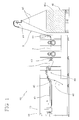
- the device 1 is applicable to machines 100 used in the manufacture of filters for tobacco products, and for cigarettes in particular, substantially of the type illustrated in figure 1.
- Such machines 100 comprise a magazine 101 holding filter material, and more exactly containing two bales 102 of filter material of which one only is illustrated in figure 1.
- Two respective tows 103 are drawn from the bales 102 and directed by means of conventional guide devices toward a station at which the filter material is processed.
- the filter material passes through a processing station comprising at least one blower device 104 of conventional type, by which the two tows 103 are expanded and formed into continuous streams F of predetermined width.
- the processing station will comprise three such blower devices 104, placed along a feed line L as illustrated in figure 1.
- the processing station further comprises a device 1 according to the invention for treating the filter material, located downstream of the blower devices 104, by which the aforementioned continuous streams F are taken up and plasticized by the application of a suitable plasticizer fluid.
- the treated streams F advance thereafter toward a stabilizing device 105 by which they are taken up on the infeed side, and from which they emerge on the outfeed side in the form of ropes 106, each advancing above a corresponding web 107 of paper coated previously with a bead of gum, and finally enveloped by these same webs 107 so as to fashion respective rods 108 of filter material.
- the rods 108 obtained in this way are fed toward a device 109 that serves to verify their density, thence to a cutter head 110 by which the selfsame rods 108 are divided transversely into respective successions of plugs, not illustrated.
- the device 1 according to the present invention for treating filter material utilized in tobacco products will now be described with reference to figure 2, which shows a preferred embodiment.
- the device 1 comprises a fixed structure 2 that presents a top portion 3 and a bottom portion 4.
- the top portion 3 of the fixed structure 2 affords guide means 5 accommodating at least one continuous stream F or ribbon of filter material.
- the guide means 5 are associated with a pair of continuous streams F of filter material advancing side by side along a given feed direction A, having entered the device 1 along relative feed lines L from upstream operating stations.
- the guide means 5 comprise respective sliding surfaces 6, disposed preferably horizontal and placed so as to support the aforementioned continuous streams F of filter material.
- the guide means 5 might comprise a plurality of rollers affording a rolling surface on which to support the continuous streams F.
- the bottom portion 4 of the fixed structure 2 forms a reservoir 7 serving to hold a plasticizer material, preferably a fluid, which is applied by the treatment device 1 disclosed to the continuous streams F of filter material by methods of familiar type, referred to hereinafter in the interests of providing a full description.
- the plasticizer fluid includes additives designed to condition the filter material by compacting and stably drawing together the constituent fibres, thereby improving their filtration properties.
- One component of the fluid preferably, will be triacetin.
- means 8 preferably rotary, by which a flow of the aforementioned plasticizer fluid is generated and directed at the streams F of filter material.
- generating means 8 comprise a revolving brush 9 rotatable about a preferably horizontal axis X disposed substantially perpendicular to the feed direction A followed by the streams F of filter material.
- the revolving brush 9 is composed of a shaft 9a rotatable about the aforementioned axis X, and a set 9b of bristles 9c carried by the shaft 9a, disposed one alongside another.
- the single bristles 9c extend radially from the shaft 9a, each presenting a first end denoted 9d, anchored to the shaft 9a, and a freely projecting second end denoted 9e.
- the free second ends 9e of the bristles 9c combine to create a substantially cylindrical active surface 10.
- the bristles 9c are fashioned of elastically deformable material, for reasons that will be explained in due course, and therefore flexible.
- the revolving brush 9 is positioned internally of the reservoir 7 containing the plasticizer fluid, underneath the streams F of filter material, and partially immersed in the fluid. With the brush 9 set in rotation, accordingly, the bristles 9c are caused repeatedly to dip into the plasticizer fluid and, on emerging, to project droplets of the fluid at the streams F of filter material.
- the rotary flow generating means 8 further comprise a counter element 11 anchored rigidly to the fixed structure 2 and placed so as to interact with the revolving brush 9.
- the counter element 11 is placed on the side of the revolving brush 9 remote from the continuous streams F of filter material, and presents a concave surface 12 offered directly to the brush 9. More exactly, the concave surface 12 is shaped substantially to match the cylindrical active surface 10 of the brush 9 and engages the set 9b of bristles 9c along a peripheral portion, as illustrated in figure 3.
- a counter blade 13 occupying an intermediate portion of the concave surface 12 and set parallel to the axis X of rotation of the revolving brush 9.
- the function of the counter blade 13 is to intercept the free second ends 9e of the bristles 9c dipped in the plasticizer fluid, which are thus caused to deform elastically as the brush 9 rotates. Once beyond the blade 13, the free second ends 9e of the bristles 9c tend to regain their undeformed state, thereby generating an elastic force that acts on the droplets of fluid attached to the ends 9e in the manner of a sling, throwing them toward the continuous streams F of filter material advancing above.
- the revolving brush 9 rotates in the anticlockwise direction, indicated by the arrow denoted R (figure 3), so as to produce the effect described above.
- the treatment device 1 further comprises feed means 14 serving to supply the plasticizer fluid, preferably associated with automatic means by which to monitor the level of the fluid in the reservoir 7.
- feed means 14 comprise one or more channels 15 by way of which the reservoir 7 is placed in fluid communication with a tank (not illustrated, being of conventional type), served possibly by pumps able to generate a head sufficient for the fluid to be drawn from the tank into the reservoir 7.
- the device 1 In order to direct the flow of plasticizer fluid onto a selected area of the continuous streams F of filter material, the device 1 also comprises a pair of ducts 16 oriented substantially in a vertical direction and of hood-like appearance; each duct 16 presents a bottom opening 16a associated with the revolving brush 9, and a top opening 16b offered directly to the respective stream F of material, in such a way that the advancing fibres skim across the mouth of the selfsame opening 16b.
- the ducts 16 are also associated with collection means 17 designed to catch any drops of plasticizer fluid scattered by continuous streams F of filter material impregnated previously.
- collection means 17 comprise two pairs of basins 18, each pair associated with a relative duct 16 and a relative stream F of filter material; more exactly, each pair is composed of a forward basin 18a positioned downstream of the duct 16, relative to the feed direction A followed by the continuous stream F, and a rear basin 18b positioned upstream of the duct 16.
- each duct 16 can be made up from sheet metal panels 19 bent to shape and incorporating the two relative basins 18a and 18b.
- the duct 16 and the two basins 18a and 18b can be enclosed on either side by lateral sheet metal panels 20 extending parallel to the feed direction A of the continuous streams F and serving also to separate the two ducts 16 and the two pairs of basins 18 one from another.
- the treatment device 1 disclosed comprises obstruction means 21 by which the flow of plasticizer fluid through the duct 16 can be cut off in a controlled manner.
- such obstruction means 21 comprise at least one movable component 22, displaceable through a plurality of operating positions between an open position, in which the plasticizer fluid is able to reach the continuous streams F of filter material, and a closed position in which the flow of plasticizer fluid directed toward the continuous streams F of filter material is cut off altogether.
- obstruction means 21 will comprise two such movable components 22, each associated with a respective continuous stream F of filter material.
- each of the movable components 22 presents a flat baffle 23 engaging a slot 24 afforded by the relative duct 16.
- the flat baffle 23 is slidable in a direction Y preferably parallel to the feed direction A followed by the two continuous streams F of filter material, and occupies a position between the rotary means 8 and the corresponding continuous stream F of filter material.
- the baffle 23 spans a full cross section of the duct 16, so that when in the closed position aforementioned, illustrated by phantom lines in figure 2, the plasticizer fluid projected from the revolving brush 9 is prevented from reaching the top opening 16b of the duct 16.
- the bent metal panels 19 of the duct 16 are fashioned each with an abutment 25 disposed substantially parallel to the sliding direction Y of the flat baffle 23 and facing toward the top opening 16b of the duct 16. Adopting this type of configuration, even though the baffle 23 may not be perfectly positioned, it will still be impossible for any part of the flow of plasticizer fluid to reach the respective continuous stream F of filter material.
- the operation of the flat baffle 23 allows transient starting phases of the device 1 to be completed without the continuous streams F of filter material being spattered with plasticizer fluid applied under non-optimal conditions, for example droplets of unsuitable size produced as a result of the brush 9 rotating too slowly, or a flow rate of the fluid different from the specified optimum flow rate, attributable to an incorrect level of plasticizer fluid in the reservoir 7.
- the flat baffle 23 is cantilevered and associated with motion-inducing means 26 by which it is also supported and guided during the aforementioned sliding movement.
- the motion-inducing and support means 26 comprise at least one linear track 27 associated rigidly with the fixed structure 2 of the device 1 and coupled freely with the flat baffle 23 in such a way that the baffle can be guided along a rectilinear and, ideally, a substantially horizontal path P.
- motion-inducing and support means 26 comprise a slide 28 coupled with a single linear track 27 and anchored rigidly to a portion of the flat baffle 23 farthest from the duct 16.
- motion-inducing and support means 26 comprise an intermediate support 29, mounted rigidly to a portion of the curved sheet metal 19 and placed to coincide with the slot 24.
- the intermediate support 29 can include suitable means, not illustrated, by which the flat baffle 23 is carried in such a manner as to minimize wear or binding.
- the motion-inducing and support means 26 could comprise two linear tracks 27 positioned one on either side of the flat baffle 23, by which the baffle can be guided along the sliding direction Y without any need to include an intermediate support 29.
- the motion-inducing and support means 26 further comprise a mechanism 30, for example of rod and crank type, mounted to the fixed structure 2 and coupled to the flat baffle 23, also drive means 31 of familiar type, such as a hydraulic cylinder 32 or alternatively an electric motor (not indicated).
- the mechanism 30 comprises a cylindrical pivot 33 rotatable about a fixed vertical axis W, associated with a bottom arm 34 and a top arm 35 each lying in a horizontal plane and presenting a respective free end 34a and 35a.
- the free end 34a of the bottom arm 34 is hinged to the hydraulic cylinder 32, whereas the free end 35a of the top arm 35 is connected to a respective baffle 23.
- the arms 34 and 35 rotate as one about the axis W of the cylindrical pivot 33, and are spaced apart one from the other substantially by a right angle, in such a way that when the free end 34a of the bottom arm 34 shifts in a direction substantially perpendicular to the sliding direction Y of the flat baffle 23, in response to a movement of the hydraulic cylinder 32 in the same direction, the free end 35a of the top arm 35 will shift in a direction substantially parallel to the sliding direction Y of the flat baffle 23, hence guiding its movement along the relative rectilinear path P.
- a slide coupling 36 comprising a block 37, also an auxiliary support 38 connected rigidly to the flat baffle 23 and affording a recess 39 in which the block 37 is slidably insertable.
- the recess 39 extends horizontally and perpendicular to the sliding direction Y of the flat baffle 2, so as to take up any movement of the sliding block 37 in a direction perpendicular to the sliding direction Y of the baffle 23, being subject only to pushing forces parallel to this same direction Y.
- the cylindrical pivot 33 is mounted straddling the fixed structure 2, so that the top arm 35 can be accommodated within the reservoir 7 containing the plasticizer fluid, whilst the bottom arm 34 and the drive means 31, advantageously, are located outside the reservoir 7.
- a mechanism 30 of the type above is associated with each of the flat baffles 23, and consequently with each continuous stream F of filter material entering the device 1.
- the drive means 31 are activated to move the baffle 23 into the closed position, shown by phantom lines in figure 2.
- the hydraulic cylinder 32 retracts and induces motion in the free end 34a of the bottom arm 34, which in turn displaces the free end 35a of the top arm 35 correspondingly along the sliding direction Y of the baffle 23.
- This same movement causes the flat baffle 23 to slide along the rectilinear path P toward the closed position.
- the reservoir 7 might be emptied during the break in operation of the device 1, for example so that cleaning operations can be carried out.
- the plasticizer fluid drained from the reservoir 7 could be recycled, perhaps after being filtered, then returned to the reservoir 7 by way of the feed means 14.
- the device 1 described by way of example in the foregoing with reference to a twin track machine in other words a machine capable of turning out two rods of filter material, can be applied equally well to a single track type machine turning out just one filter rod.
- the means by which to obstruct the flow of plasticizer fluid can be associated equally well with a single continuous stream of filter material, so as to bring about a controlled interruption of the flow of plasticizer fluid directed toward the selfsame stream.
Landscapes
- Cigarettes, Filters, And Manufacturing Of Filters (AREA)
- Filtering Of Dispersed Particles In Gases (AREA)
Abstract
Description
- The present invention relates to a device for the treatment of filter material utilized in tobacco products, typically cigarettes.
- In particular, the invention finds application in cigarette filter making machines.
- Conventionally, the manufacture of filter tips for cigarettes, be it with simple or composite type filter plugs, involves processing a filter material consisting for instance in a ribbon or stream of fibrous cellulose acetate tow.
- The fibrous tow material in question is drawn from compacted bales and passed through processing stations where it is stretched initially, then impregnated with plasticizers, and finally folded or bunched around the longitudinal axis of the ribbon or stream to form a continuous rod, which is enveloped in a paper plugwrap.
- Conventionally, the impregnating step takes place as the stretched ribbon is directed through special devices designed to invest the advancing material with a flow of plasticizer, typically triacetin, a substance which at the normal operating temperature and pressure of the devices in question will remain in the liquid state.
- The ribbon is thus sprayed with a flow of liquid consisting in particles of predetermined quantity and size, in such a way that a prescribed quantity of the triacetin will be absorbed.
- Prior art devices utilized to perform the step described above comprise adjustable nozzles from which a flow of triacetin is directed toward the ribbon being impregnated. Devices of this type have a high maintenance requirement, however, given the need for cleaning and adjustment of the nozzles.
- Other prior art type devices used to implement the step in question comprise a container, or bath, holding a predetermined quantity of triacetin, and a revolving brush partly immersed in the triacetin, which when set in rotation at a normal operating speed will project a flow of liquid droplets toward a ribbon of cellulose acetate advancing in close proximity.
- It has been noted that there is an optimum speed at which the brush should rotate when part-immersed in the triacetin. In reality, whilst the angular velocity of the brush directly influences the size of the droplets of triacetin projected onto the ribbon, it does not directly influence the quantity of triacetin actually transferred to the ribbon; this, by contrast, depends directly on the depth to which the brush is immersed in the bath of liquid. Accordingly, use is made generally of feed means by which the triacetin is maintained at a constant level in the container during the operation of the device, for example a pump connected to a tank and in fluid communication with the container.
- In the event of a malfunction occurring, devices of conventional type will cause the brush to cease rotation, so that no further triacetin is pumped into the container.
- It has been found, however, that when the device is restarted and the brush resumes rotation, the initial movement has the effect of inducing a wave in the mass of liquid, affecting its correct flow toward the ribbon of filter material and causing the material to be impregnated non-uniformly. Whilst the effect disappears once normal operating conditions are restored, the portions of ribbon treated previously must be discarded as they will have been sprayed by droplets of triacetin in less than optimum conditions. The portions of ribbon in question are impregnated non-uniformly and may be of appreciable proportions, given that the starting transient can be somewhat lengthy.
- The prior art also embraces devices that operate by removing the triacetin from the container when a stoppage occurs, whereupon the brush is restarted dry and the container then replenished gradually with triacetin as the brush rotates at the optimum speed. Such devices in any event do not solve the problem of having to discard substantial portions of the ribbon of filter material, given that in the course of the transient during which the container is refilled, the level of triacetin remains lower than optimum and therefore impacts negatively on the quantity of the liquid utilized to condition the ribbon, with the consequence that the requisite impregnation properties of the filter material are not established. Moreover, the process of emptying and filling the container takes time and involves constructional complexities connected with the recirculation of the plasticizer fluid.
- Accordingly, the object of the present invention is to provide a device for the treatment of filter material used in tobacco products, substantially unaffected by the drawbacks mentioned above.
- In particular, the object of the invention is to provide a device for treating filter material used in tobacco products, such as will allow of limiting the quantity of ribbon discarded during transients in operation.
- A further object of the invention is to provide a device for the treatment of filter material used in tobacco products that does not require a bath of plasticizer fluid to be emptied systematically in the event of malfunction or breakdown.
- The stated objects are realized according to the invention in a device for the treatment of filter material used in tobacco products, of which the features are recited in the appended claims.
- The invention will now be described in detail, by way of example, with the aid of the accompanying drawings, in which:
- figure 1 illustrates a cigarette filter making machine, equipped with a device according to the present invention;
- figure 2 is a sectional view of a device according to the present invention;
- figure 3 is a sectional view showing a portion of the device in figure 2.
- With reference to the accompanying drawings,
numeral 1 denotes a device, in its entirety, for treating filter material used in tobacco products, in accordance with the present invention. - The
device 1 is applicable to machines 100 used in the manufacture of filters for tobacco products, and for cigarettes in particular, substantially of the type illustrated in figure 1. - Such machines 100 comprise a magazine 101 holding filter material, and more exactly containing two bales 102 of filter material of which one only is illustrated in figure 1. Two respective tows 103 are drawn from the bales 102 and directed by means of conventional guide devices toward a station at which the filter material is processed.
- In detail, the filter material passes through a processing station comprising at least one blower device 104 of conventional type, by which the two tows 103 are expanded and formed into continuous streams F of predetermined width. In a preferred embodiment, the processing station will comprise three such blower devices 104, placed along a feed line L as illustrated in figure 1. The processing station further comprises a
device 1 according to the invention for treating the filter material, located downstream of the blower devices 104, by which the aforementioned continuous streams F are taken up and plasticized by the application of a suitable plasticizer fluid. - The treated streams F advance thereafter toward a stabilizing device 105 by which they are taken up on the infeed side, and from which they emerge on the outfeed side in the form of ropes 106, each advancing above a corresponding web 107 of paper coated previously with a bead of gum, and finally enveloped by these same webs 107 so as to fashion respective rods 108 of filter material.
- The rods 108 obtained in this way are fed toward a device 109 that serves to verify their density, thence to a cutter head 110 by which the selfsame rods 108 are divided transversely into respective successions of plugs, not illustrated.
- The
device 1 according to the present invention for treating filter material utilized in tobacco products will now be described with reference to figure 2, which shows a preferred embodiment. - The
device 1 comprises afixed structure 2 that presents atop portion 3 and abottom portion 4. Thetop portion 3 of thefixed structure 2 affords guide means 5 accommodating at least one continuous stream F or ribbon of filter material. In the case of the preferred embodiment illustrated, the guide means 5 are associated with a pair of continuous streams F of filter material advancing side by side along a given feed direction A, having entered thedevice 1 along relative feed lines L from upstream operating stations. More exactly, the guide means 5 comprise respectivesliding surfaces 6, disposed preferably horizontal and placed so as to support the aforementioned continuous streams F of filter material. Alternatively, in a further embodiment (not illustrated), the guide means 5 might comprise a plurality of rollers affording a rolling surface on which to support the continuous streams F. - The
bottom portion 4 of thefixed structure 2 forms a reservoir 7 serving to hold a plasticizer material, preferably a fluid, which is applied by thetreatment device 1 disclosed to the continuous streams F of filter material by methods of familiar type, referred to hereinafter in the interests of providing a full description. The plasticizer fluid includes additives designed to condition the filter material by compacting and stably drawing together the constituent fibres, thereby improving their filtration properties. One component of the fluid, preferably, will be triacetin. - Also forming part of the
treatment device 1 are means 8, preferably rotary, by which a flow of the aforementioned plasticizer fluid is generated and directed at the streams F of filter material. In the example of figure 3, such generating means 8 comprise a revolvingbrush 9 rotatable about a preferably horizontal axis X disposed substantially perpendicular to the feed direction A followed by the streams F of filter material. - The revolving
brush 9 is composed of ashaft 9a rotatable about the aforementioned axis X, and aset 9b ofbristles 9c carried by theshaft 9a, disposed one alongside another. - The
single bristles 9c extend radially from theshaft 9a, each presenting a first end denoted 9d, anchored to theshaft 9a, and a freely projecting second end denoted 9e. The free second ends 9e of thebristles 9c combine to create a substantially cylindricalactive surface 10. In addition, thebristles 9c are fashioned of elastically deformable material, for reasons that will be explained in due course, and therefore flexible. - The revolving
brush 9 is positioned internally of the reservoir 7 containing the plasticizer fluid, underneath the streams F of filter material, and partially immersed in the fluid. With thebrush 9 set in rotation, accordingly, thebristles 9c are caused repeatedly to dip into the plasticizer fluid and, on emerging, to project droplets of the fluid at the streams F of filter material. - To improve the effectiveness of the
bristles 9c, the rotary flow generating means 8 further comprise acounter element 11 anchored rigidly to thefixed structure 2 and placed so as to interact with the revolvingbrush 9. Thecounter element 11 is placed on the side of the revolvingbrush 9 remote from the continuous streams F of filter material, and presents aconcave surface 12 offered directly to thebrush 9. More exactly, theconcave surface 12 is shaped substantially to match the cylindricalactive surface 10 of thebrush 9 and engages theset 9b ofbristles 9c along a peripheral portion, as illustrated in figure 3. - Also associated with the
counter element 11 is acounter blade 13 occupying an intermediate portion of theconcave surface 12 and set parallel to the axis X of rotation of the revolvingbrush 9. The function of thecounter blade 13 is to intercept the free second ends 9e of thebristles 9c dipped in the plasticizer fluid, which are thus caused to deform elastically as thebrush 9 rotates. Once beyond theblade 13, the free second ends 9e of thebristles 9c tend to regain their undeformed state, thereby generating an elastic force that acts on the droplets of fluid attached to the ends 9e in the manner of a sling, throwing them toward the continuous streams F of filter material advancing above. Observing the particular layout of thedevice 1 shown in figure 2, the revolvingbrush 9 rotates in the anticlockwise direction, indicated by the arrow denoted R (figure 3), so as to produce the effect described above. - To maintain the plasticizer fluid at a constant level in the reservoir 7, the
treatment device 1 further comprises feed means 14 serving to supply the plasticizer fluid, preferably associated with automatic means by which to monitor the level of the fluid in the reservoir 7. Such feed means 14 comprise one ormore channels 15 by way of which the reservoir 7 is placed in fluid communication with a tank (not illustrated, being of conventional type), served possibly by pumps able to generate a head sufficient for the fluid to be drawn from the tank into the reservoir 7. - In order to direct the flow of plasticizer fluid onto a selected area of the continuous streams F of filter material, the
device 1 also comprises a pair ofducts 16 oriented substantially in a vertical direction and of hood-like appearance; eachduct 16 presents a bottom opening 16a associated with the revolvingbrush 9, and a top opening 16b offered directly to the respective stream F of material, in such a way that the advancing fibres skim across the mouth of theselfsame opening 16b. - The
ducts 16 are also associated with collection means 17 designed to catch any drops of plasticizer fluid scattered by continuous streams F of filter material impregnated previously. Such collection means 17 comprise two pairs of basins 18, each pair associated with arelative duct 16 and a relative stream F of filter material; more exactly, each pair is composed of aforward basin 18a positioned downstream of theduct 16, relative to the feed direction A followed by the continuous stream F, and arear basin 18b positioned upstream of theduct 16. For constructional purposes, eachduct 16 can be made up fromsheet metal panels 19 bent to shape and incorporating the tworelative basins duct 16 and the twobasins sheet metal panels 20 extending parallel to the feed direction A of the continuous streams F and serving also to separate the twoducts 16 and the two pairs of basins 18 one from another. - To the end of overcoming the drawbacks associated with the prior art, advantageously, the
treatment device 1 disclosed comprises obstruction means 21 by which the flow of plasticizer fluid through theduct 16 can be cut off in a controlled manner. - In particular, such obstruction means 21 comprise at least one
movable component 22, displaceable through a plurality of operating positions between an open position, in which the plasticizer fluid is able to reach the continuous streams F of filter material, and a closed position in which the flow of plasticizer fluid directed toward the continuous streams F of filter material is cut off altogether. - In a preferred embodiment, obstruction means 21 will comprise two such
movable components 22, each associated with a respective continuous stream F of filter material. - As discernible in figure 2, each of the
movable components 22 presents aflat baffle 23 engaging aslot 24 afforded by therelative duct 16. Theflat baffle 23 is slidable in a direction Y preferably parallel to the feed direction A followed by the two continuous streams F of filter material, and occupies a position between the rotary means 8 and the corresponding continuous stream F of filter material. Thebaffle 23 spans a full cross section of theduct 16, so that when in the closed position aforementioned, illustrated by phantom lines in figure 2, the plasticizer fluid projected from the revolvingbrush 9 is prevented from reaching thetop opening 16b of theduct 16. To optimize this function, thebent metal panels 19 of theduct 16 are fashioned each with anabutment 25 disposed substantially parallel to the sliding direction Y of theflat baffle 23 and facing toward thetop opening 16b of theduct 16. Adopting this type of configuration, even though thebaffle 23 may not be perfectly positioned, it will still be impossible for any part of the flow of plasticizer fluid to reach the respective continuous stream F of filter material. - When the
baffle 23 is retracted substantially in its entirety from the closed position, no longer fully occupying the cross section of theduct 16, it will assume the configuration indicated by the solid lines of figure 2, coinciding with the open position aforementioned, in which the plasticizer fluid projected from the revolvingbrush 9 is able to reach thetop opening 16b of theduct 16. - To advantage, the operation of the
flat baffle 23 allows transient starting phases of thedevice 1 to be completed without the continuous streams F of filter material being spattered with plasticizer fluid applied under non-optimal conditions, for example droplets of unsuitable size produced as a result of thebrush 9 rotating too slowly, or a flow rate of the fluid different from the specified optimum flow rate, attributable to an incorrect level of plasticizer fluid in the reservoir 7. - In the example illustrated, the
flat baffle 23 is cantilevered and associated with motion-inducingmeans 26 by which it is also supported and guided during the aforementioned sliding movement. The motion-inducing and support means 26 comprise at least one linear track 27 associated rigidly with the fixedstructure 2 of thedevice 1 and coupled freely with theflat baffle 23 in such a way that the baffle can be guided along a rectilinear and, ideally, a substantially horizontal path P. In the example of figure 2, motion-inducing and support means 26 comprise aslide 28 coupled with a single linear track 27 and anchored rigidly to a portion of theflat baffle 23 farthest from theduct 16. Likewise preferably, motion-inducing and support means 26 comprise anintermediate support 29, mounted rigidly to a portion of thecurved sheet metal 19 and placed to coincide with theslot 24. Theintermediate support 29 can include suitable means, not illustrated, by which theflat baffle 23 is carried in such a manner as to minimize wear or binding. - In an alternative solution, not illustrated, the motion-inducing and support means 26 could comprise two linear tracks 27 positioned one on either side of the
flat baffle 23, by which the baffle can be guided along the sliding direction Y without any need to include anintermediate support 29. - The motion-inducing and support means 26 further comprise a mechanism 30, for example of rod and crank type, mounted to the fixed
structure 2 and coupled to theflat baffle 23, also drive means 31 of familiar type, such as ahydraulic cylinder 32 or alternatively an electric motor (not indicated). In detail, and as discernible from the example of figure 2, the mechanism 30 comprises acylindrical pivot 33 rotatable about a fixed vertical axis W, associated with abottom arm 34 and atop arm 35 each lying in a horizontal plane and presenting a respectivefree end free end 34a of thebottom arm 34 is hinged to thehydraulic cylinder 32, whereas thefree end 35a of thetop arm 35 is connected to arespective baffle 23. - The
arms cylindrical pivot 33, and are spaced apart one from the other substantially by a right angle, in such a way that when thefree end 34a of thebottom arm 34 shifts in a direction substantially perpendicular to the sliding direction Y of theflat baffle 23, in response to a movement of thehydraulic cylinder 32 in the same direction, thefree end 35a of thetop arm 35 will shift in a direction substantially parallel to the sliding direction Y of theflat baffle 23, hence guiding its movement along the relative rectilinear path P. - Moreover, the
free end 35a of thetop branch 35 and the relativeflat baffle 23 are connected by way of aslide coupling 36 comprising ablock 37, also anauxiliary support 38 connected rigidly to theflat baffle 23 and affording arecess 39 in which theblock 37 is slidably insertable. More particularly, therecess 39 extends horizontally and perpendicular to the sliding direction Y of theflat baffle 2, so as to take up any movement of the slidingblock 37 in a direction perpendicular to the sliding direction Y of thebaffle 23, being subject only to pushing forces parallel to this same direction Y. - In addition, the
cylindrical pivot 33 is mounted straddling the fixedstructure 2, so that thetop arm 35 can be accommodated within the reservoir 7 containing the plasticizer fluid, whilst thebottom arm 34 and the drive means 31, advantageously, are located outside the reservoir 7. - A mechanism 30 of the type above is associated with each of the
flat baffles 23, and consequently with each continuous stream F of filter material entering thedevice 1. - Starting from an operating configuration in which the
flat baffle 23 occupies the aforementioned open position, indicated by the solid lines in figure 2, with the continuous streams F advancing along the feed direction A while being impregnated with the plasticizer fluid, the occurrence of a malfunction or a breakdown causes thedevice 1 to shut down. In particular, the motion of the continuous streams F will cease, the rotary means 8 will come to a halt, and the feed means 14 supplying plasticizer fluid to the reservoir 7, which are associated with the rotary means 8, will be deactivated. - Thereafter, the drive means 31 are activated to move the
baffle 23 into the closed position, shown by phantom lines in figure 2. In particular, thehydraulic cylinder 32 retracts and induces motion in thefree end 34a of thebottom arm 34, which in turn displaces thefree end 35a of thetop arm 35 correspondingly along the sliding direction Y of thebaffle 23. This same movement causes theflat baffle 23 to slide along the rectilinear path P toward the closed position. - Only at a later stage is it possible to restore the feed motion of the continuous streams F and to restart the rotary means 8. Once the rotary means 8 regain normal operating speed, the drive means 31 will be able to return the
flat baffle 23 to the open position. At this juncture, the continuous streams F of filter material can be impregnated in accordance with the optimum conditions specified by the design. - In a variation on the procedure described above, the reservoir 7 might be emptied during the break in operation of the
device 1, for example so that cleaning operations can be carried out. In this instance, the plasticizer fluid drained from the reservoir 7 could be recycled, perhaps after being filtered, then returned to the reservoir 7 by way of the feed means 14. - Without prejudice to the spirit of the invention, it will be appreciated that the
device 1 described by way of example in the foregoing with reference to a twin track machine, in other words a machine capable of turning out two rods of filter material, can be applied equally well to a single track type machine turning out just one filter rod. In other words, the means by which to obstruct the flow of plasticizer fluid can be associated equally well with a single continuous stream of filter material, so as to bring about a controlled interruption of the flow of plasticizer fluid directed toward the selfsame stream.
Claims (15)
- A device for the treatment of filter material used in tobacco products, toward which at least one continuous stream (F) of filter material is fed from a respective line (L) supplying the selfsame material, comprising rotary means (8) by which a flow of plasticizer fluid is generated and directed at the continuous stream (F) of filter material
characterized
in that it further comprises obstruction means (21) by which the flow of plasticizer fluid directed at the continuous stream (F) of filter material can be cut off in a controlled manner. - A device as in claim 1, wherein flow obstruction means (21) comprise at least one movable component (22) displaceable between an open position, in which the flow of plasticizer fluid is able to reach the stream (F) of filter material, and a closed position in which the flow of plasticizer fluid directed toward the continuous stream (F) of filter material is cut off altogether.
- A device as in claim 2, wherein the movable component (22) consists in a flat baffle (23) slidable between the open position and the closed position.
- A device as in claim 2 or 3, further comprising a fixed structure (2) serving to guide one or more continuous streams (F) of filter material along respective feed directions (A), and affording a reservoir (7) in which the plasticizer fluid is collected.
- A device as in claims 2 to 4, wherein the movable component (22) is positioned between the rotary means (8) and the continuous stream or streams (F) of filter material.
- A device as in claim 4 where dependent on claim 3, wherein the flat baffle (23) is associated with at least one linear track (27) fastened rigidly to the fixed structure (2).
- A device as in claim 6, wherein the at least one track (27) establishes a substantially rectilinear path (P).
- A device as in claim 7, wherein the rectilinear path (P) is substantially horizontal.
- A device as in claims 6 to 8, comprising one linear track (27) and a slide (28) supported slidably by the linear track (27), wherein the flat baffle (23) is connected rigidly to the slide (28).
- A device as in claims 3 to 9, wherein the flat baffle (23) is associated slidably with a slidable block (37) constituting a portion of a rod and crank mechanism (30) by which the flat baffle (23) is caused to move between the open and closed positions.
- A device as in claim 4, comprising feed means (14) supplying the plasticizer fluid, by which the level of plasticizer fluid in the reservoir (7) is maintained constant.
- A device as in preceding claims, wherein the rotary means (8) generating the flow of plasticizer fluid comprise a revolving brush (9), partially immersed in the selfsame fluid and designed to generate the flow when set in rotation.
- A device as in claim 12, wherein the revolving brush (9) is furnished with a plurality of flexible bristles (9c) located one beside another, each presenting a first end (9d) anchored permanently to a shaft (9a) of the brush (9), and a free second end (9e).
- A device as in preceding claims, wherein the plasticizer fluid includes triacetin.
- A machine for manufacturing cigarette filters, in which one or more continuous streams (F) of filter material are fed by respective lines (L) supplying the selfsame material, each designed to advance a respective continuous stream (F) of filter material toward a station at which the stream (F) of filter material is processed,
characterized
in that the processing station comprises a device (1) for the treatment of filter material used in tobacco products, as recited in one or more of the preceding claims.
Applications Claiming Priority (1)
| Application Number | Priority Date | Filing Date | Title |
|---|---|---|---|
| ITBO20060301 ITBO20060301A1 (en) | 2006-04-21 | 2006-04-21 | DEVICE FOR HOLDING FILTERING MATERIAL FOR SMOKE ITEMS |
Publications (1)
| Publication Number | Publication Date |
|---|---|
| EP1847188A1 true EP1847188A1 (en) | 2007-10-24 |
Family
ID=37056950
Family Applications (1)
| Application Number | Title | Priority Date | Filing Date |
|---|---|---|---|
| EP07106369A Withdrawn EP1847188A1 (en) | 2006-04-21 | 2007-04-18 | A device for the treatment of filter material used in tobacco products |
Country Status (3)
| Country | Link |
|---|---|
| EP (1) | EP1847188A1 (en) |
| JP (1) | JP2007289190A (en) |
| IT (1) | ITBO20060301A1 (en) |
Cited By (1)
| Publication number | Priority date | Publication date | Assignee | Title |
|---|---|---|---|---|
| EP3011847A1 (en) | 2014-10-24 | 2016-04-27 | G.D Societa' per Azioni | Unit and method for applying an additive on a cigarette filter manufacturing machine |
Families Citing this family (1)
| Publication number | Priority date | Publication date | Assignee | Title |
|---|---|---|---|---|
| ITBO20110272A1 (en) * | 2011-05-16 | 2012-11-17 | Gd Spa | DEVICE FOR THE TREATMENT OF FILTERING MATERIAL FOR SMOKE ITEMS. |
Citations (6)
| Publication number | Priority date | Publication date | Assignee | Title |
|---|---|---|---|---|
| US4040385A (en) * | 1976-05-03 | 1977-08-09 | Grundig E.M.V. Elektro-Mechanische Versuchsanstalt Max Grundig | Apparatus for depositing flux-fluid onto conductor plates |
| GB2078559A (en) * | 1980-06-20 | 1982-01-13 | Hauni Werke Koerber & Co Kg | Applying liquid plasticizer to filamentary filter material |
| GB2090774A (en) * | 1980-12-12 | 1982-07-21 | Molins Ltd | Applying fluid additive as a foam to fibrous material |
| GB2109273A (en) * | 1981-11-16 | 1983-06-02 | Brown & Williamson Tobacco Corp | Applying plasticizers to fibrous filter material |
| US5342657A (en) * | 1992-11-16 | 1994-08-30 | Philip Morris Incorporated | Apparatus and method for applying fluid to a moving continuous web |
| DE10354924A1 (en) * | 2003-11-25 | 2005-06-30 | Hauni Maschinenbau Ag | Device for processing filter tow material and device for producing filters |
-
2006
- 2006-04-21 IT ITBO20060301 patent/ITBO20060301A1/en unknown
-
2007
- 2007-04-18 EP EP07106369A patent/EP1847188A1/en not_active Withdrawn
- 2007-04-20 JP JP2007111915A patent/JP2007289190A/en active Pending
Patent Citations (6)
| Publication number | Priority date | Publication date | Assignee | Title |
|---|---|---|---|---|
| US4040385A (en) * | 1976-05-03 | 1977-08-09 | Grundig E.M.V. Elektro-Mechanische Versuchsanstalt Max Grundig | Apparatus for depositing flux-fluid onto conductor plates |
| GB2078559A (en) * | 1980-06-20 | 1982-01-13 | Hauni Werke Koerber & Co Kg | Applying liquid plasticizer to filamentary filter material |
| GB2090774A (en) * | 1980-12-12 | 1982-07-21 | Molins Ltd | Applying fluid additive as a foam to fibrous material |
| GB2109273A (en) * | 1981-11-16 | 1983-06-02 | Brown & Williamson Tobacco Corp | Applying plasticizers to fibrous filter material |
| US5342657A (en) * | 1992-11-16 | 1994-08-30 | Philip Morris Incorporated | Apparatus and method for applying fluid to a moving continuous web |
| DE10354924A1 (en) * | 2003-11-25 | 2005-06-30 | Hauni Maschinenbau Ag | Device for processing filter tow material and device for producing filters |
Cited By (1)
| Publication number | Priority date | Publication date | Assignee | Title |
|---|---|---|---|---|
| EP3011847A1 (en) | 2014-10-24 | 2016-04-27 | G.D Societa' per Azioni | Unit and method for applying an additive on a cigarette filter manufacturing machine |
Also Published As
| Publication number | Publication date |
|---|---|
| JP2007289190A (en) | 2007-11-08 |
| ITBO20060301A1 (en) | 2006-07-21 |
Similar Documents
| Publication | Publication Date | Title |
|---|---|---|
| EP1161887B1 (en) | Method for applying a fluid to a wrapper paper web | |
| AU2004233645B2 (en) | Improvements relating to material application to rod wrappers | |
| US20040038790A1 (en) | Method and apparatus for applying additive to a moving, spread-out filter material web | |
| DE2505998A1 (en) | DEVICE FOR REMOVING ROD-SHAPED ARTICLES OF THE TOBACCO-PROCESSING INDUSTRY FROM A STORAGE | |
| DE19639260A1 (en) | Applying glue to packet flaps etc. | |
| EP1250855B1 (en) | Method and device for eliminating a disturbance from a tobacco channel in a rod making machine | |
| DE3813786C2 (en) | Device for cutting a strand of the tobacco processing industry | |
| JP2007289190A (en) | Device for the treatment of filter material used in tobacco products | |
| DE3835314A1 (en) | STRING GUIDE FOR THE CUTTER OF A CIGARETTE STRANDING MACHINE | |
| EP1886589B1 (en) | A device for the treatment of filter material used in tobacco products | |
| DE2226261A1 (en) | METHOD AND DEVICE FOR MEASURING A CUTTING TOBACCO FLOW | |
| US3411942A (en) | Method of applying liquid addendum to opposite surfaces of a continuous multifilament tow | |
| DE60001793T2 (en) | CLEANING DEVICE FOR A RUBBER DEVICE | |
| EP1834529B1 (en) | Treatment of a filter material rod of the tobacco processing industry | |
| CN105533805A (en) | Unit and method for applying an additive on a cigarette filter manufacturing machine | |
| DE3127181C2 (en) | ||
| EP2709474B1 (en) | Device for the treatment of filter material for tobacco products | |
| EP2695532B1 (en) | Apparatus for applying a liquid substance to at least one belt in a machine for making tobacco products | |
| DE102006027597A1 (en) | Method for operating a stranding machine and stranding machine | |
| US20050245374A1 (en) | Apparatus for applying additive to filter tow | |
| EP1691632B1 (en) | Oscillator for a printing group of the tobacco-processing industry | |
| DE3122557C2 (en) | ||
| DE1241736B (en) | Method and apparatus for forming a continuous stream of tobacco | |
| DE1778513C3 (en) | Device for moistening shirred sausage casings | |
| DE102005051523A1 (en) | Device for preparing strip of filter material in tobacco processing industry, has suction device which is provided outside housing of application device to extract air surrounding application device |
Legal Events
| Date | Code | Title | Description |
|---|---|---|---|
| PUAI | Public reference made under article 153(3) epc to a published international application that has entered the european phase |
Free format text: ORIGINAL CODE: 0009012 |
|
| AK | Designated contracting states |
Kind code of ref document: A1 Designated state(s): AT BE BG CH CY CZ DE DK EE ES FI FR GB GR HU IE IS IT LI LT LU LV MC MT NL PL PT RO SE SI SK TR |
|
| AX | Request for extension of the european patent |
Extension state: AL BA HR MK YU |
|
| 17P | Request for examination filed |
Effective date: 20071204 |
|
| AKX | Designation fees paid |
Designated state(s): AT BE BG CH CY CZ DE DK EE ES FI FR GB GR HU IE IS IT LI LT LU LV MC MT NL PL PT RO SE SI SK TR |
|
| TPAC | Observations filed by third parties |
Free format text: ORIGINAL CODE: EPIDOSNTIPA |
|
| 17Q | First examination report despatched |
Effective date: 20091008 |
|
| STAA | Information on the status of an ep patent application or granted ep patent |
Free format text: STATUS: THE APPLICATION IS DEEMED TO BE WITHDRAWN |
|
| 18D | Application deemed to be withdrawn |
Effective date: 20100219 |