EP1846292B1 - Aircraft seat supporting structure - Google Patents
Aircraft seat supporting structure Download PDFInfo
- Publication number
- EP1846292B1 EP1846292B1 EP05818951.5A EP05818951A EP1846292B1 EP 1846292 B1 EP1846292 B1 EP 1846292B1 EP 05818951 A EP05818951 A EP 05818951A EP 1846292 B1 EP1846292 B1 EP 1846292B1
- Authority
- EP
- European Patent Office
- Prior art keywords
- support structure
- side members
- seat
- extending
- members
- Prior art date
- Legal status (The legal status is an assumption and is not a legal conclusion. Google has not performed a legal analysis and makes no representation as to the accuracy of the status listed.)
- Expired - Lifetime
Links
Images
Classifications
-
- B—PERFORMING OPERATIONS; TRANSPORTING
- B64—AIRCRAFT; AVIATION; COSMONAUTICS
- B64D—EQUIPMENT FOR FITTING IN OR TO AIRCRAFT; FLIGHT SUITS; PARACHUTES; ARRANGEMENT OR MOUNTING OF POWER PLANTS OR PROPULSION TRANSMISSIONS IN AIRCRAFT
- B64D11/00—Passenger or crew accommodation; Flight-deck installations not otherwise provided for
- B64D11/06—Arrangements of seats, or adaptations or details specially adapted for aircraft seats
- B64D11/0639—Arrangements of seats, or adaptations or details specially adapted for aircraft seats with features for adjustment or converting of seats
- B64D11/0641—Seats convertible into beds
-
- B—PERFORMING OPERATIONS; TRANSPORTING
- B60—VEHICLES IN GENERAL
- B60N—SEATS SPECIALLY ADAPTED FOR VEHICLES; VEHICLE PASSENGER ACCOMMODATION NOT OTHERWISE PROVIDED FOR
- B60N2/00—Seats specially adapted for vehicles; Arrangement or mounting of seats in vehicles
- B60N2/005—Arrangement or mounting of seats in vehicles, e.g. dismountable auxiliary seats
- B60N2/015—Attaching seats directly to vehicle chassis
-
- B—PERFORMING OPERATIONS; TRANSPORTING
- B64—AIRCRAFT; AVIATION; COSMONAUTICS
- B64D—EQUIPMENT FOR FITTING IN OR TO AIRCRAFT; FLIGHT SUITS; PARACHUTES; ARRANGEMENT OR MOUNTING OF POWER PLANTS OR PROPULSION TRANSMISSIONS IN AIRCRAFT
- B64D11/00—Passenger or crew accommodation; Flight-deck installations not otherwise provided for
- B64D11/06—Arrangements of seats, or adaptations or details specially adapted for aircraft seats
- B64D11/0606—Arrangements of seats, or adaptations or details specially adapted for aircraft seats with privacy shells, screens, separators or the like
-
- Y—GENERAL TAGGING OF NEW TECHNOLOGICAL DEVELOPMENTS; GENERAL TAGGING OF CROSS-SECTIONAL TECHNOLOGIES SPANNING OVER SEVERAL SECTIONS OF THE IPC; TECHNICAL SUBJECTS COVERED BY FORMER USPC CROSS-REFERENCE ART COLLECTIONS [XRACs] AND DIGESTS
- Y02—TECHNOLOGIES OR APPLICATIONS FOR MITIGATION OR ADAPTATION AGAINST CLIMATE CHANGE
- Y02T—CLIMATE CHANGE MITIGATION TECHNOLOGIES RELATED TO TRANSPORTATION
- Y02T50/00—Aeronautics or air transport
- Y02T50/40—Weight reduction
Definitions
- This invention relates to aircraft seating and seating arrangements.
- the invention is particularly, but not exclusively, applicable to seating for commercial aircraft.
- the movable portion is movable between a fully reclined position and an upright position.
- a recess is disposed below the back rest and seat pan in the upright position, the recess constituting a foot-well for a person using another seat therebehind.
- Front and rear crossmembers can be fixedly secured respectively to the lower ends of the front and rear legs, and are fixed to seat tracks provided in the vehicle.
- the fixed portion includes two spaced rear legs that are positioned on opposing sides of the recess, and the rear cross-member can be fixedly secured to the lower ends of both of the rear legs.
- WO03/013903 discloses a seat unit for an aircraft that can be converted into a bed.
- the seat unit comprises a supporting structure for attaching a seat to the floor of the aircraft.
- the supporting structure comprises a load bearing aerospace-grade steel subframe which is clad with one or more shaped composite panels.
- the steel subframe provides a structurally strong point of attachment for the passenger seat and other components of the seat unit.
- Embodiments of the invention are based on the realisation that structural frames having sufficient structural performance to comply with the stringent aviation safety regulations can be obtained by careful design of a structure.
- Using composite materials for the structural, load bearing, frame or support structure of the aircraft seat results in significant weight savings as compared with prior metal subframe designs.
- Any reference to composite or fibre-reinforced composite materials herein is understood to refer to any material comprising a reinforcing material such as carbon or glass fibres embedded in a matrix of a secondary material, usually a polymer.
- the reference to composite or fibre-reinforced composite materials also includes materials which are laminates of layers of composite materials and/or core materials such as a honeycomb material, for example, an aluminium or plastics honeycomb core.
- the structural frame comprises side members spaced apart by a cross member which is designed to distribute any load or sheer forces over a relatively large area at the interface between the side members and the cross members. Additional structural stability is achieved by integrally including additional elements forming a backshell member within the structural frame.
- a seat unit for an aircraft cabin comprises a back shell 10 and load bearing side frame members 12 and 14, each defining an integral arm 16.
- the side members and backshell each comprise decorative cladding 18 that covers the rigid structural frame members 12 and 14 that support the constituent parts of a seat 20.
- the parts of the seat are a seat base 22, a leg rest 24 and a back rest 26.
- the seat base 22, in this embodiment, is arranged to slide longitudinally and/or to be adjustable for seat base angle, according to passenger preference, by means of slots formed in each of the frame members 12/14 in which the parts of the seat ride.
- the seat back rest 26 is adjustable as part of a seat configuration.
- leg rest 24 is essentially conventional in function, being either manually, pneumatically or electrically deployable. It is pivotably mounted at a point 28 at or near the front of the seat base 20.
- the components of the seat unit are covered in suitable cushioning and material in appropriate areas, such as the arms, seat base and seat back. These are omitted from the drawings showing the component parts for the sake of clarity.
- the seat back 26 is mounted to pivot at a point 29 about or near its junction with the seat base 22 to fold forward on top of the seat base 22. As with the seat base, the seat back 26 is mounted for slidable movement between the two side frame members 12 and 14.
- the leg rest 24 is mounted on the front seat base 22, as described.
- the side frame members 12 and 14 are spaced by one, or more than one, cross member both to provide rigidity for the structure and to mount components such as the actuating mechanisms for movement of the seat components that have to be supported between the side frames 12 and 14.
- FIG.1 The structural frame that supports the seat of Fig.1 is now described with reference to Figs.2 and 3A and B , whereby the direction which is substantially perpendicular to the aircraft floor on which the seat rests is referred to as vertical, the direction along arm rest 16 is referred to as the longitudinal direction and the direction across seat base 20, perpendicular to the vertical and lateral direction is referred to as lateral.
- the notional plane of the aircraft floor or ground is referred to as horizontal.
- the structural frame comprises load bearing side members 30 and 40, each having a slot 32, 42 which is situated approximately halfway between the bottom 34, 44 and the top 36, 46 (acting as a base for arm rest 16) of each side member. Slots 32 and 42 are arranged, when the structural frame is assembled, to act as a guide and locator in which the parts of the seat ride. It is understood that slots 32 and 42 can be replaced by any other suitable means for securing a seat for continuous movement between a first and second position, for example a ledge. Side members 30, 40 further comprise protrusions forming horizontal ledges 38,48 extending transversally which provide a connecting surface for bonding to a cross member 50, which spaces side members 30 and 40.
- the cross member 50 comprises a plate extending transversely between side member 30 and 40 and defines an S-shaped profile in the lateral/vertical plane.
- the cross member 50 thus comprises two surfaces 51 and 52 respectively extending vertically in the downwards direction and upwardly at an intermediate angle, and a horizontal surface 53 extending laterally and longitudinally and generally parallel beneath the seat base 20.
- the side and cross members (30, 40, 50) hence define a hollow box section of four sides between them. It is understood that the box section may have more than four sides (e.g. being closed at the bottom) and that the angles between the sides are not limited to be rectangular and may be rounded over a region of the box section.
- Cross member 50 further comprises vertical surfaces 54 situated at the lateral edges.
- the vertical surfaces 54 provide a further surface for bonding cross member 50 to the ledges 38, 48 on the side members 30 and 40.
- a further lateral lip 58 is formed at the lower end of cross member 50 which, in-cooperation with lower ends 34 and 44 of side members 30 and 40, forms part of the overall surface of the structural frame that rests on the aircraft floor when the seat is installed.
- the lip 58 comprises a downwardly facing recess 59 for accepting a track fixing interface or ground engaging member 90 for fixing the seat to the aircraft floor.
- Member 90 comprises a first set of holes 92 for bolting it to corresponding holes 96 in side members 30 and 40 and a second set of holes 94 for bolting it to the aircraft floor.
- a further track fixing member 100 is situated towards the rear of the seat assembly. It also comprises a first set of holes 102 for bolting member 100 to corresponding holes 104 towards the rear in side members 30 and 40 and a second set of holes for fixing to the aircraft floor (not shown).
- Side members 30 and 40 comprise a further rear horizontal surface 39/49 at the rear end of each of the ledges 30, 40, which act as an interface for bonding backshell 10 to the structural frame assembly. It will be seen from Figure 2 that the backshell 10 is made up of a back part 60 and two sides 70 and 80.
- the corresponding bonding surfaces 72 and 82 on the backshell 10 are formed on the respective sides 70 and 80.
- Sides 70 and 80 are bonded to back wall 60 along their lateral edges 74, 84 and 62, respectively.
- the front edge 64 of the back wall 60 is bonded to the rear edge 57 of cross member 50. Integrally bonding the backshell to the structural frame further contributes to the structural stability of the frame.
- a structural frame or support structure for supporting the passenger seat is formed, which supports the passenger seat above a substantially cuboidal structural base defined on four sides by the side members and the cross member and by the floor to which the structure is secured.
- the bonding surfaces 54, 38 and 48 form an interface with projections covering substantially all of the lateral and vertical extent of side members 30 and 40 underneath the passenger seat (apart from cutout 56 in horizontal surface 53).
- This extended, elongate interface between side members 30 and 40 and cross member 50 distributes any load onto a much larger surface than, for example, the relatively small interaction surfaces of conventional bolted cross members.
- fibre-reinforced composite materials can be employed rather than the conventional aerospace grade steel or aluminium machined, pressed or cast members.
- the structural frame of the specific embodiment described above with reference to Figures 2 and 3A and B is constructed from shaped reinforced fibre composite and honeycomb laminates.
- Any reinforced fibre composite material may be used, but carbon fibre based composites with a Phenolic Resin matrix have been found to be advantageous in terms of weight saving.
- Other fibres such as glass, polyamide (e.g. Kevlar, registered trade mark) may also be also be advantageous.
- the use of epoxy or polyester matrices is equally envisaged.
- Any suitable honeycomb may be used to form the laminate, but the specific embodiment uses an aluminium honeycomb core (Aeroweb produced by Cyba-Geigy, registered trade marks).
- the laminate parts are bonded together using methacrylate.
- the backshell 10 is constructed from a laminate of aluminium honeycomb sandwiched between three layers of biaxial carbon fibre composites with a resulting thickness of under 14mm in this embodiment.
- the structural frame comprising the side members 30, 40 and cross member 50 is constructed from a laminate of aluminium honeycomb sandwiched between 5 layers of biaxial carbon fibre composite on each side, resulting in a thickness of less than 15mms in this embodiment.
- the thicker of the two materials has a density of just under 400kg/m 3 , which is substantially less than the density of corresponding aluminium parts which would be in the region of 3000kg/m 2 or even higher for steel parts.
- Track fixing members 90 and 100 are manufactured as aluminium extrusions having a density of 2800kg/m 2 , but do not contribute significantly to the overall weight due to the small volumes involved. The structure described above thus results in significant weight savings as compared with traditional steel or aluminium subframe constructions.
- the decorative cladding 18 shown in Figure 1 may also contribute to the structural stability of the frame.
- the cladding may be made from structurally sufficiently strong material to add to the overall stability.
- the cladding may be of the same material as the other parts and may be bonded thereto using a structural adhesive (although any other means of securing the cladding is also envisaged).
- a double-skinned construction with added stability is achieved.
- Figure 3B shows the surfaces of the structural frame to which the cladding may be attached, denoted by 41 for the side members and 71 for the backshell.
- a cavity 43 is thus defined between the respective cladding and the side member 40 and a cavity 73 is defined between the respective cladding and the backshell 70.
- the cavities 73 and 43 can be used to stow and conceal auxiliary equipment and/or accessories of the seat.
- a suitable video screen such as an LED screen, and/or reading or ambient lights may be installed in cavity 73 (in combination with suitable cut-outs in the backshell 10 or cladding).
- any electrical circuitry or circuit board can be stowed in the cavity so that it is concealed, and is not exposed to damage.
- the structural frame may be formed as a single laminate structure or the adhesive bonds between laminate parts may be replaced by other securing means.
Landscapes
- Engineering & Computer Science (AREA)
- Aviation & Aerospace Engineering (AREA)
- Transportation (AREA)
- Mechanical Engineering (AREA)
- Laminated Bodies (AREA)
- Seats For Vehicles (AREA)
Description
- This invention relates to aircraft seating and seating arrangements. The invention is particularly, but not exclusively, applicable to seating for commercial aircraft.
- It is becoming increasingly necessary for airlines to install a seat in a commercial aircraft that converts into a bed, at least in first class on long haul flights. The conflicting commercial considerations are the provision of a good service, on the one hand, and the pressure to maintain cabin seating density and weight considerations, on the other. Thus, it has become the goal of the seat designer to make as much use of as little space and weight as possible while providing the necessary level of space and comfort expected in first and business class.
-
US 6,276,635 Bldiscloses a seating unit for a vehicle, particularly an aircraft, that has a movable portion including a back rest, a seat pan and a leg rest, and a fixed portion having front and rear legs. The movable portion is movable between a fully reclined position and an upright position. A recess is disposed below the back rest and seat pan in the upright position, the recess constituting a foot-well for a person using another seat therebehind. Front and rear crossmembers can be fixedly secured respectively to the lower ends of the front and rear legs, and are fixed to seat tracks provided in the vehicle. In one embodiment, the fixed portion includes two spaced rear legs that are positioned on opposing sides of the recess, and the rear cross-member can be fixedly secured to the lower ends of both of the rear legs. -
WO03/013903 - The use of a steel subframe in constructing sleeper/seat units for aircraft can be understood from the need to comply with stringent safety regulations aimed at ensuring that a seat unit can withstand the foreseeable loads and stresses which may arise during a crash of the aircraft. Due to these stringent safety regulations, there is thus an apparent prejudice in the field of aircraft seat construction against using other materials for the structural component of a seat.
- The present invention is defined claim 1. Some preferred features are recited in the dependent claims.
- Embodiments of the invention are based on the realisation that structural frames having sufficient structural performance to comply with the stringent aviation safety regulations can be obtained by careful design of a structure. Using composite materials for the structural, load bearing, frame or support structure of the aircraft seat results in significant weight savings as compared with prior metal subframe designs. Any reference to composite or fibre-reinforced composite materials herein is understood to refer to any material comprising a reinforcing material such as carbon or glass fibres embedded in a matrix of a secondary material, usually a polymer. The reference to composite or fibre-reinforced composite materials also includes materials which are laminates of layers of composite materials and/or core materials such as a honeycomb material, for example, an aluminium or plastics honeycomb core.
- The structural frame comprises side members spaced apart by a cross member which is designed to distribute any load or sheer forces over a relatively large area at the interface between the side members and the cross members. Additional structural stability is achieved by integrally including additional elements forming a backshell member within the structural frame.
- The invention can be put into practice in various ways, some of which will now be described by way of example with reference to the accompanying drawings in which:
-
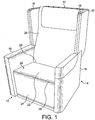
Fig.1 is a perspective view of an embodiment of a seat for an aircraft; -
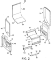
Fig.2 is an exploded perspective view of a structural frame of the seat inFig.1 ; and -
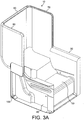
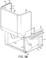
Fig.3A andB are perspective views of the assembled structural frame ofFig.2 . - Referring to
Fig.1 , a seat unit for an aircraft cabin comprises aback shell 10 and load bearingside frame members integral arm 16. In this embodiment, the side members and backshell each comprisedecorative cladding 18 that covers the rigidstructural frame members seat 20. The parts of the seat are aseat base 22, a leg rest 24 and aback rest 26. Theseat base 22, in this embodiment, is arranged to slide longitudinally and/or to be adjustable for seat base angle, according to passenger preference, by means of slots formed in each of theframe members 12/14 in which the parts of the seat ride. Likewise, theseat back rest 26 is adjustable as part of a seat configuration. - In this case, conventional manual or electrically motorised slide mechanisms can be used, as are known from conventional seats for this type of application. The
leg rest 24 is essentially conventional in function, being either manually, pneumatically or electrically deployable. It is pivotably mounted at a point 28 at or near the front of theseat base 20. - It will be appreciated that the components of the seat unit are covered in suitable cushioning and material in appropriate areas, such as the arms, seat base and seat back. These are omitted from the drawings showing the component parts for the sake of clarity.
- The
seat back 26 is mounted to pivot at apoint 29 about or near its junction with theseat base 22 to fold forward on top of theseat base 22. As with the seat base, theseat back 26 is mounted for slidable movement between the twoside frame members leg rest 24 is mounted on thefront seat base 22, as described. Theside frame members side frames - The structural frame that supports the seat of
Fig.1 is now described with reference toFigs.2 and3A andB , whereby the direction which is substantially perpendicular to the aircraft floor on which the seat rests is referred to as vertical, the direction alongarm rest 16 is referred to as the longitudinal direction and the direction acrossseat base 20, perpendicular to the vertical and lateral direction is referred to as lateral. The notional plane of the aircraft floor or ground is referred to as horizontal. - The structural frame comprises load bearing
side members slot bottom top 36, 46 (acting as a base for arm rest 16) of each side member.Slots slots Side members horizontal ledges cross member 50, whichspaces side members - The
cross member 50 comprises a plate extending transversely betweenside member cross member 50 thus comprises twosurfaces horizontal surface 53 extending laterally and longitudinally and generally parallel beneath theseat base 20. - The side and cross members (30, 40, 50) hence define a hollow box section of four sides between them. It is understood that the box section may have more than four sides (e.g. being closed at the bottom) and that the angles between the sides are not limited to be rectangular and may be rounded over a region of the box section.
-
Cross member 50 further comprisesvertical surfaces 54 situated at the lateral edges. Thevertical surfaces 54 provide a further surface for bondingcross member 50 to theledges side members lateral lip 58 is formed at the lower end ofcross member 50 which, in-cooperation withlower ends side members lip 58 comprises a downwardly facingrecess 59 for accepting a track fixing interface or groundengaging member 90 for fixing the seat to the aircraft floor.Member 90 comprises a first set ofholes 92 for bolting it to correspondingholes 96 inside members holes 94 for bolting it to the aircraft floor. A furthertrack fixing member 100 is situated towards the rear of the seat assembly. It also comprises a first set ofholes 102 for boltingmember 100 tocorresponding holes 104 towards the rear inside members -
Side members ledges bonding backshell 10 to the structural frame assembly. It will be seen fromFigure 2 that thebackshell 10 is made up of aback part 60 and twosides - The
corresponding bonding surfaces backshell 10 are formed on therespective sides Sides back wall 60 along theirlateral edges front edge 64 of theback wall 60 is bonded to therear edge 57 ofcross member 50. Integrally bonding the backshell to the structural frame further contributes to the structural stability of the frame. - Considering
side members cross member 50 in isolation, a structural frame or support structure for supporting the passenger seat is formed, which supports the passenger seat above a substantially cuboidal structural base defined on four sides by the side members and the cross member and by the floor to which the structure is secured. In this arrangement, the bonding surfaces 54, 38 and 48 form an interface with projections covering substantially all of the lateral and vertical extent ofside members side members cross member 50 distributes any load onto a much larger surface than, for example, the relatively small interaction surfaces of conventional bolted cross members. Such a structure which is designed to distribute forces allows the use of a much larger range of materials in the construction of the structural frame than previously possible. In particular, fibre-reinforced composite materials can be employed rather than the conventional aerospace grade steel or aluminium machined, pressed or cast members. - The fact that the nature of the interface between the members of the structural frame, described above, distributes load and stress forces evenly across the members compensates for the relatively lower yield stress of, for example, fibre-reinforced composite laminates perpendicular to the plane of the fibres in order to exploit the relatively high yield stress these materials exhibit within this plane. A much lighter structural frame than conventional steel or aluminium frames can thus be constructed by using materials which have high yield stress in the dimensions where it is crucial by compensating for the relatively lower yield stress in other dimensions through design of the frame structure to produce a rigid shape.
- The structural frame of the specific embodiment described above with reference to
Figures 2 and3A andB is constructed from shaped reinforced fibre composite and honeycomb laminates. Any reinforced fibre composite material may be used, but carbon fibre based composites with a Phenolic Resin matrix have been found to be advantageous in terms of weight saving. Other fibres such as glass, polyamide (e.g. Kevlar, registered trade mark) may also be also be advantageous. The use of epoxy or polyester matrices is equally envisaged. Any suitable honeycomb may be used to form the laminate, but the specific embodiment uses an aluminium honeycomb core (Aeroweb produced by Cyba-Geigy, registered trade marks). - The laminate parts are bonded together using methacrylate.
- In the specific embodiment described above, the
backshell 10 is constructed from a laminate of aluminium honeycomb sandwiched between three layers of biaxial carbon fibre composites with a resulting thickness of under 14mm in this embodiment. The structural frame comprising theside members cross member 50 is constructed from a laminate of aluminium honeycomb sandwiched between 5 layers of biaxial carbon fibre composite on each side, resulting in a thickness of less than 15mms in this embodiment. The thicker of the two materials has a density of just under 400kg/m3, which is substantially less than the density of corresponding aluminium parts which would be in the region of 3000kg/m2 or even higher for steel parts.Track fixing members - The
decorative cladding 18 shown inFigure 1 may also contribute to the structural stability of the frame. To exploit this, the cladding may be made from structurally sufficiently strong material to add to the overall stability. For example, the cladding may be of the same material as the other parts and may be bonded thereto using a structural adhesive (although any other means of securing the cladding is also envisaged). Thus, a double-skinned construction with added stability is achieved. -
Figure 3B shows the surfaces of the structural frame to which the cladding may be attached, denoted by 41 for the side members and 71 for the backshell. Acavity 43 is thus defined between the respective cladding and theside member 40 and acavity 73 is defined between the respective cladding and thebackshell 70. - The
cavities backshell 10 or cladding). - Similarly, any electrical circuitry or circuit board can be stowed in the cavity so that it is concealed, and is not exposed to damage.
- It is understood that features of the specific embodiment described above may be altered, omitted or juxtaposed without departing from the scope of the intention. For example, the structural frame may be formed as a single laminate structure or the adhesive bonds between laminate parts may be replaced by other securing means.
- The embodiment discussed above describes a frame structure for an aircraft seat. It will be apparent to the skilled person that such a frame structure can be employed to construct an aircraft seating unit by providing a passenger seat and other fittings. The specific embodiment described above is meant to illustrate, by way of example only, the invention, which is defined by the wording of the claims set out below.
Claims (12)
- A support structure for an aircraft seat comprising:first (30) and second (40) load bearing spaced side members each having means for securing a seat for continuous movement between first and second positions and a ground engaging portion; anda cross member (50) extending between the first (30) and second (40) load bearing spaced side members, the cross member (50) defining an S-shaped profile in the lateral/vertical plane and comprising a horizontal surface (53), a surface (51) extending from the horizontal surface vertically in a downwards direction, and a surface (52) extending from the horizontal surface upwardly at an intermediate angle, characterized in thatthe first (30) and second (40) load bearing spaced side members, the horizontal surface (53) and the surface (51) extending from the horizontal surface vertically in a downwards direction substantially define four sides of a substantially cuboidal hollow box section to stiffen the side members at least in a region beneath the means for securing the seat.
- A support structure as claimed in claim 1, in which the box section has 5 sides.
- A support structure as claimed in claims 1 or 2, in which the spaced side members (30, 40) and the cross member (50) are substantially made of fibre reinforced composite material.
- An aircraft seat structural frame as claimed in claim 3, wherein the fibre reinforced composite materials comprise a sandwich of layers of carbon fibre reinforced composite with a honeycomb core.
- A support structure as claimed in any preceding claim, wherein the box section extends substantially from the means for securing to the ground engaging members.
- A support structure as claimed in any preceding claim the structure further comprising a back shell (10) extending laterally between the side members.
- A support structure as claimed in any preceding claim, the ground engaging portion comprising aluminium cross members extending laterally between the side members.
- A support structure as claimed in any preceding claim, the means for securing comprising a slot (32, 42).
- A support structure as claimed in any one of the preceding claims in which at least part of the structure includes a double-skin construction defining an interior cavity.
- A support structure as claimed in any one of the preceding claims in which the side members define an interior cavity (43) therein.
- A support structure as claimed in any one of claims 6 to 10 when dependent on claim 6 in which the backshell defines a interior cavity (73) therein.
- A support structure as claimed in claim 11 in which the interior cavity (73) in the backshell houses auxiliary equipment, for example a video screen or a light source.
Applications Claiming Priority (2)
| Application Number | Priority Date | Filing Date | Title |
|---|---|---|---|
| GBGB0426527.8A GB0426527D0 (en) | 2004-12-02 | 2004-12-02 | Aircraft seat supporting structure |
| PCT/GB2005/004615 WO2006059118A1 (en) | 2004-12-02 | 2005-12-02 | Aircraft seat supporting structure |
Publications (2)
| Publication Number | Publication Date |
|---|---|
| EP1846292A1 EP1846292A1 (en) | 2007-10-24 |
| EP1846292B1 true EP1846292B1 (en) | 2020-06-10 |
Family
ID=34043986
Family Applications (1)
| Application Number | Title | Priority Date | Filing Date |
|---|---|---|---|
| EP05818951.5A Expired - Lifetime EP1846292B1 (en) | 2004-12-02 | 2005-12-02 | Aircraft seat supporting structure |
Country Status (5)
| Country | Link |
|---|---|
| US (1) | US8087612B2 (en) |
| EP (1) | EP1846292B1 (en) |
| JP (1) | JP2008521703A (en) |
| GB (1) | GB0426527D0 (en) |
| WO (1) | WO2006059118A1 (en) |
Cited By (2)
| Publication number | Priority date | Publication date | Assignee | Title |
|---|---|---|---|---|
| EP3608167A4 (en) * | 2017-04-03 | 2020-12-16 | Jamco Corporation | REAR SHELL STRUCTURE AND SEAT UNIT |
| EP3608168B1 (en) * | 2017-04-03 | 2022-08-03 | Jamco Corporation | Seat unit and bottom structure thereof |
Families Citing this family (15)
| Publication number | Priority date | Publication date | Assignee | Title |
|---|---|---|---|---|
| CA2581738C (en) | 2001-08-09 | 2009-04-14 | Virgin Atlantic Airways Limited | A seating system and a passenger accomodation unit for a vehicle |
| USD583579S1 (en) | 2004-06-18 | 2008-12-30 | Virgin Atlantic Airways Limited | Airplane seating unit |
| DE102006007977A1 (en) * | 2006-02-21 | 2007-09-13 | Recaro Aircraft Seating Gmbh & Co. Kg | Aircraft seat fastening device |
| US8375839B2 (en) * | 2007-08-29 | 2013-02-19 | Supracor, Inc. | Lightweight armor and ballistic projectile defense apparatus |
| WO2013138582A1 (en) * | 2012-03-14 | 2013-09-19 | B/E Aerospace, Inc. | Composite structural element and method |
| EP2697117B1 (en) * | 2012-07-06 | 2019-08-28 | Zodiac Seats France | Base frame assembly for passenger seats |
| US9856024B2 (en) * | 2013-06-18 | 2018-01-02 | B/E Aerospace, Inc. | Compact aircraft cabin attendant seat |
| EP3620377B1 (en) * | 2015-04-08 | 2022-11-09 | Safran Seats USA LLC | Privacy shell |
| FR3056481B1 (en) * | 2016-09-28 | 2018-11-23 | Stelia Aerospace | VEHICLE ARMCHAIRS WITH MODULAR CLADDING SHELL |
| US10329021B2 (en) * | 2016-12-16 | 2019-06-25 | Ami Industries, Inc. | Collapsible backrest |
| JP7043180B2 (en) * | 2017-04-03 | 2022-03-29 | 株式会社ジャムコ | Structure for seat unit, seat unit and its mounting method |
| GB2579809B (en) * | 2018-12-14 | 2023-04-12 | Safran Seats Gb Ltd | A kit of parts for assembling an aircraft seat unit |
| DE102020106035A1 (en) | 2020-03-05 | 2021-09-09 | Zim Flugsitz Gmbh | Passenger seat with a connecting device and row of seats |
| DE102020106039A1 (en) | 2020-03-05 | 2021-09-09 | Zim Flugsitz Gmbh | Passenger seat and row of seats |
| FR3112527B1 (en) * | 2020-07-17 | 2022-12-23 | Stelia Aerospace | Framework for an aircraft seat made up of cut and assembled flat parts and its method of manufacture |
Family Cites Families (7)
| Publication number | Priority date | Publication date | Assignee | Title |
|---|---|---|---|---|
| GB8331260D0 (en) * | 1983-11-23 | 1983-12-29 | Toll I C | Aircraft seats |
| US5482351A (en) * | 1993-07-19 | 1996-01-09 | Erda, Inc. | Aircraft seat with crash absorbsion mechanism |
| US5522182A (en) * | 1994-03-04 | 1996-06-04 | Rogers; Jesse | Stadium seating |
| GB9706650D0 (en) * | 1997-04-02 | 1997-05-21 | Virgin Atlantic Airways Ltd | A seat |
| CA2581738C (en) | 2001-08-09 | 2009-04-14 | Virgin Atlantic Airways Limited | A seating system and a passenger accomodation unit for a vehicle |
| DE10224048B4 (en) * | 2002-05-31 | 2006-07-13 | Airbus Deutschland Gmbh | Passenger seat, especially for a commercial aircraft |
| DE202004008069U1 (en) | 2004-05-13 | 2004-07-29 | Tricon Aktiengesellschaft | Seat assembly for especially passengers in aircraft has stowage compartment for hand luggage and is located below level of sitting surface or below foot level, with sitting surface raised by the height of stowage compartment |
-
2004
- 2004-12-02 GB GBGB0426527.8A patent/GB0426527D0/en not_active Ceased
-
2005
- 2005-12-02 WO PCT/GB2005/004615 patent/WO2006059118A1/en not_active Ceased
- 2005-12-02 EP EP05818951.5A patent/EP1846292B1/en not_active Expired - Lifetime
- 2005-12-02 JP JP2007543917A patent/JP2008521703A/en active Pending
- 2005-12-02 US US11/791,012 patent/US8087612B2/en not_active Expired - Fee Related
Non-Patent Citations (1)
| Title |
|---|
| None * |
Cited By (2)
| Publication number | Priority date | Publication date | Assignee | Title |
|---|---|---|---|---|
| EP3608167A4 (en) * | 2017-04-03 | 2020-12-16 | Jamco Corporation | REAR SHELL STRUCTURE AND SEAT UNIT |
| EP3608168B1 (en) * | 2017-04-03 | 2022-08-03 | Jamco Corporation | Seat unit and bottom structure thereof |
Also Published As
| Publication number | Publication date |
|---|---|
| WO2006059118A1 (en) | 2006-06-08 |
| US20090065643A1 (en) | 2009-03-12 |
| EP1846292A1 (en) | 2007-10-24 |
| US8087612B2 (en) | 2012-01-03 |
| JP2008521703A (en) | 2008-06-26 |
| GB0426527D0 (en) | 2005-01-05 |
Similar Documents
| Publication | Publication Date | Title |
|---|---|---|
| EP1846292B1 (en) | Aircraft seat supporting structure | |
| EP2550200B1 (en) | Passenger seat assembly with associated floor panel and aircraft sidewall attachment, and method | |
| US7717519B2 (en) | Composite seat back structure for a lightweight aircraft seat assembly | |
| US8550564B1 (en) | Composite seat pan structure for a lightweight aircraft seat assembly | |
| US7338013B2 (en) | Floor for aircraft | |
| US8590126B2 (en) | Method of manufacturing a composite leg structure for a lightweight aircraft seat assembly | |
| US20180016010A1 (en) | Large self-carrying monument assembly for an aircraft and an aircraft having such a monument assembly | |
| US8360362B2 (en) | Aircraft floor and method of assembly | |
| US9359078B2 (en) | Aircraft galley monument structure | |
| US8393574B2 (en) | Composite leg structure for a lightweight aircraft seat assembly | |
| US20100187894A1 (en) | Composite Seat Pan Structure For A Lightweight Aircraft Seat Assembly | |
| JP5246943B2 (en) | Facility for fixing floor panels and layout members including such panels | |
| US20060038071A1 (en) | Flush-top seat mounting rail for passenger aircraft | |
| US10730628B2 (en) | Aircraft seat back with non-tubular perimeter flange | |
| US20110233339A1 (en) | Passenger seat assembly and associated floor panel structure | |
| US11753168B2 (en) | Seat unit and lower structure thereof | |
| EP3847053B1 (en) | Light weight metal back with extra living space | |
| CA3195502A1 (en) | Integrated partition wall arrangement having a cabin attendant seat | |
| HK1178498A1 (en) | Use of a lightweight construction element | |
| HK1178498B (en) | Use of a lightweight construction element |
Legal Events
| Date | Code | Title | Description |
|---|---|---|---|
| PUAI | Public reference made under article 153(3) epc to a published international application that has entered the european phase |
Free format text: ORIGINAL CODE: 0009012 |
|
| 17P | Request for examination filed |
Effective date: 20070627 |
|
| AK | Designated contracting states |
Kind code of ref document: A1 Designated state(s): AT BE BG CH CY CZ DE DK EE ES FI FR GB GR HU IE IS IT LI LT LU LV MC NL PL PT RO SE SI SK TR |
|
| DAX | Request for extension of the european patent (deleted) | ||
| 17Q | First examination report despatched |
Effective date: 20090112 |
|
| STAA | Information on the status of an ep patent application or granted ep patent |
Free format text: STATUS: EXAMINATION IS IN PROGRESS |
|
| GRAP | Despatch of communication of intention to grant a patent |
Free format text: ORIGINAL CODE: EPIDOSNIGR1 |
|
| STAA | Information on the status of an ep patent application or granted ep patent |
Free format text: STATUS: GRANT OF PATENT IS INTENDED |
|
| INTG | Intention to grant announced |
Effective date: 20191206 |
|
| GRAS | Grant fee paid |
Free format text: ORIGINAL CODE: EPIDOSNIGR3 |
|
| GRAJ | Information related to disapproval of communication of intention to grant by the applicant or resumption of examination proceedings by the epo deleted |
Free format text: ORIGINAL CODE: EPIDOSDIGR1 |
|
| GRAL | Information related to payment of fee for publishing/printing deleted |
Free format text: ORIGINAL CODE: EPIDOSDIGR3 |
|
| STAA | Information on the status of an ep patent application or granted ep patent |
Free format text: STATUS: EXAMINATION IS IN PROGRESS |
|
| INTC | Intention to grant announced (deleted) | ||
| GRAR | Information related to intention to grant a patent recorded |
Free format text: ORIGINAL CODE: EPIDOSNIGR71 |
|
| STAA | Information on the status of an ep patent application or granted ep patent |
Free format text: STATUS: GRANT OF PATENT IS INTENDED |
|
| GRAA | (expected) grant |
Free format text: ORIGINAL CODE: 0009210 |
|
| STAA | Information on the status of an ep patent application or granted ep patent |
Free format text: STATUS: THE PATENT HAS BEEN GRANTED |
|
| REG | Reference to a national code |
Ref country code: DE Ref legal event code: R081 Ref document number: 602005056873 Country of ref document: DE Owner name: JAMES PARK ASSOCIATES LTD., GB Free format text: FORMER OWNER: JAMES PARK ASSOCIATES LTD., LONDON, GB |
|
| AK | Designated contracting states |
Kind code of ref document: B1 Designated state(s): AT BE BG CH CY CZ DE DK EE ES FI FR GB GR HU IE IS IT LI LT LU LV MC NL PL PT RO SE SI SK TR |
|
| INTG | Intention to grant announced |
Effective date: 20200504 |
|
| REG | Reference to a national code |
Ref country code: GB Ref legal event code: FG4D |
|
| REG | Reference to a national code |
Ref country code: AT Ref legal event code: REF Ref document number: 1278979 Country of ref document: AT Kind code of ref document: T Effective date: 20200615 Ref country code: CH Ref legal event code: EP |
|
| RAP2 | Party data changed (patent owner data changed or rights of a patent transferred) |
Owner name: JAMES PARK ASSOCIATES INTERNATIONAL LIMITED |
|
| REG | Reference to a national code |
Ref country code: DE Ref legal event code: R096 Ref document number: 602005056873 Country of ref document: DE |
|
| REG | Reference to a national code |
Ref country code: IE Ref legal event code: FG4D |
|
| REG | Reference to a national code |
Ref country code: LT Ref legal event code: MG4D |
|
| PG25 | Lapsed in a contracting state [announced via postgrant information from national office to epo] |
Ref country code: LT Free format text: LAPSE BECAUSE OF FAILURE TO SUBMIT A TRANSLATION OF THE DESCRIPTION OR TO PAY THE FEE WITHIN THE PRESCRIBED TIME-LIMIT Effective date: 20200610 Ref country code: SE Free format text: LAPSE BECAUSE OF FAILURE TO SUBMIT A TRANSLATION OF THE DESCRIPTION OR TO PAY THE FEE WITHIN THE PRESCRIBED TIME-LIMIT Effective date: 20200610 Ref country code: GR Free format text: LAPSE BECAUSE OF FAILURE TO SUBMIT A TRANSLATION OF THE DESCRIPTION OR TO PAY THE FEE WITHIN THE PRESCRIBED TIME-LIMIT Effective date: 20200911 Ref country code: FI Free format text: LAPSE BECAUSE OF FAILURE TO SUBMIT A TRANSLATION OF THE DESCRIPTION OR TO PAY THE FEE WITHIN THE PRESCRIBED TIME-LIMIT Effective date: 20200610 |
|
| REG | Reference to a national code |
Ref country code: NL Ref legal event code: MP Effective date: 20200610 |
|
| PG25 | Lapsed in a contracting state [announced via postgrant information from national office to epo] |
Ref country code: LV Free format text: LAPSE BECAUSE OF FAILURE TO SUBMIT A TRANSLATION OF THE DESCRIPTION OR TO PAY THE FEE WITHIN THE PRESCRIBED TIME-LIMIT Effective date: 20200610 Ref country code: BG Free format text: LAPSE BECAUSE OF FAILURE TO SUBMIT A TRANSLATION OF THE DESCRIPTION OR TO PAY THE FEE WITHIN THE PRESCRIBED TIME-LIMIT Effective date: 20200910 |
|
| REG | Reference to a national code |
Ref country code: AT Ref legal event code: MK05 Ref document number: 1278979 Country of ref document: AT Kind code of ref document: T Effective date: 20200610 |
|
| PG25 | Lapsed in a contracting state [announced via postgrant information from national office to epo] |
Ref country code: NL Free format text: LAPSE BECAUSE OF FAILURE TO SUBMIT A TRANSLATION OF THE DESCRIPTION OR TO PAY THE FEE WITHIN THE PRESCRIBED TIME-LIMIT Effective date: 20200610 |
|
| PG25 | Lapsed in a contracting state [announced via postgrant information from national office to epo] |
Ref country code: RO Free format text: LAPSE BECAUSE OF FAILURE TO SUBMIT A TRANSLATION OF THE DESCRIPTION OR TO PAY THE FEE WITHIN THE PRESCRIBED TIME-LIMIT Effective date: 20200610 Ref country code: ES Free format text: LAPSE BECAUSE OF FAILURE TO SUBMIT A TRANSLATION OF THE DESCRIPTION OR TO PAY THE FEE WITHIN THE PRESCRIBED TIME-LIMIT Effective date: 20200610 Ref country code: CZ Free format text: LAPSE BECAUSE OF FAILURE TO SUBMIT A TRANSLATION OF THE DESCRIPTION OR TO PAY THE FEE WITHIN THE PRESCRIBED TIME-LIMIT Effective date: 20200610 Ref country code: PT Free format text: LAPSE BECAUSE OF FAILURE TO SUBMIT A TRANSLATION OF THE DESCRIPTION OR TO PAY THE FEE WITHIN THE PRESCRIBED TIME-LIMIT Effective date: 20201012 Ref country code: EE Free format text: LAPSE BECAUSE OF FAILURE TO SUBMIT A TRANSLATION OF THE DESCRIPTION OR TO PAY THE FEE WITHIN THE PRESCRIBED TIME-LIMIT Effective date: 20200610 Ref country code: AT Free format text: LAPSE BECAUSE OF FAILURE TO SUBMIT A TRANSLATION OF THE DESCRIPTION OR TO PAY THE FEE WITHIN THE PRESCRIBED TIME-LIMIT Effective date: 20200610 |
|
| PG25 | Lapsed in a contracting state [announced via postgrant information from national office to epo] |
Ref country code: IS Free format text: LAPSE BECAUSE OF FAILURE TO SUBMIT A TRANSLATION OF THE DESCRIPTION OR TO PAY THE FEE WITHIN THE PRESCRIBED TIME-LIMIT Effective date: 20201010 Ref country code: SK Free format text: LAPSE BECAUSE OF FAILURE TO SUBMIT A TRANSLATION OF THE DESCRIPTION OR TO PAY THE FEE WITHIN THE PRESCRIBED TIME-LIMIT Effective date: 20200610 Ref country code: PL Free format text: LAPSE BECAUSE OF FAILURE TO SUBMIT A TRANSLATION OF THE DESCRIPTION OR TO PAY THE FEE WITHIN THE PRESCRIBED TIME-LIMIT Effective date: 20200610 |
|
| REG | Reference to a national code |
Ref country code: DE Ref legal event code: R097 Ref document number: 602005056873 Country of ref document: DE |
|
| PLBE | No opposition filed within time limit |
Free format text: ORIGINAL CODE: 0009261 |
|
| STAA | Information on the status of an ep patent application or granted ep patent |
Free format text: STATUS: NO OPPOSITION FILED WITHIN TIME LIMIT |
|
| PG25 | Lapsed in a contracting state [announced via postgrant information from national office to epo] |
Ref country code: DK Free format text: LAPSE BECAUSE OF FAILURE TO SUBMIT A TRANSLATION OF THE DESCRIPTION OR TO PAY THE FEE WITHIN THE PRESCRIBED TIME-LIMIT Effective date: 20200610 |
|
| 26N | No opposition filed |
Effective date: 20210311 |
|
| PG25 | Lapsed in a contracting state [announced via postgrant information from national office to epo] |
Ref country code: SI Free format text: LAPSE BECAUSE OF FAILURE TO SUBMIT A TRANSLATION OF THE DESCRIPTION OR TO PAY THE FEE WITHIN THE PRESCRIBED TIME-LIMIT Effective date: 20200610 |
|
| REG | Reference to a national code |
Ref country code: CH Ref legal event code: PL |
|
| PG25 | Lapsed in a contracting state [announced via postgrant information from national office to epo] |
Ref country code: MC Free format text: LAPSE BECAUSE OF FAILURE TO SUBMIT A TRANSLATION OF THE DESCRIPTION OR TO PAY THE FEE WITHIN THE PRESCRIBED TIME-LIMIT Effective date: 20200610 |
|
| REG | Reference to a national code |
Ref country code: BE Ref legal event code: MM Effective date: 20201231 |
|
| PG25 | Lapsed in a contracting state [announced via postgrant information from national office to epo] |
Ref country code: IE Free format text: LAPSE BECAUSE OF NON-PAYMENT OF DUE FEES Effective date: 20201202 Ref country code: LU Free format text: LAPSE BECAUSE OF NON-PAYMENT OF DUE FEES Effective date: 20201202 |
|
| PG25 | Lapsed in a contracting state [announced via postgrant information from national office to epo] |
Ref country code: CH Free format text: LAPSE BECAUSE OF NON-PAYMENT OF DUE FEES Effective date: 20201231 Ref country code: LI Free format text: LAPSE BECAUSE OF NON-PAYMENT OF DUE FEES Effective date: 20201231 |
|
| PG25 | Lapsed in a contracting state [announced via postgrant information from national office to epo] |
Ref country code: TR Free format text: LAPSE BECAUSE OF FAILURE TO SUBMIT A TRANSLATION OF THE DESCRIPTION OR TO PAY THE FEE WITHIN THE PRESCRIBED TIME-LIMIT Effective date: 20200610 Ref country code: CY Free format text: LAPSE BECAUSE OF FAILURE TO SUBMIT A TRANSLATION OF THE DESCRIPTION OR TO PAY THE FEE WITHIN THE PRESCRIBED TIME-LIMIT Effective date: 20200610 |
|
| PG25 | Lapsed in a contracting state [announced via postgrant information from national office to epo] |
Ref country code: BE Free format text: LAPSE BECAUSE OF NON-PAYMENT OF DUE FEES Effective date: 20201231 |
|
| PGFP | Annual fee paid to national office [announced via postgrant information from national office to epo] |
Ref country code: GB Payment date: 20221014 Year of fee payment: 18 Ref country code: FR Payment date: 20221212 Year of fee payment: 18 |
|
| PGFP | Annual fee paid to national office [announced via postgrant information from national office to epo] |
Ref country code: IT Payment date: 20221221 Year of fee payment: 18 Ref country code: DE Payment date: 20221229 Year of fee payment: 18 |
|
| REG | Reference to a national code |
Ref country code: DE Ref legal event code: R119 Ref document number: 602005056873 Country of ref document: DE |
|
| GBPC | Gb: european patent ceased through non-payment of renewal fee |
Effective date: 20231202 |
|
| PG25 | Lapsed in a contracting state [announced via postgrant information from national office to epo] |
Ref country code: DE Free format text: LAPSE BECAUSE OF NON-PAYMENT OF DUE FEES Effective date: 20240702 |
|
| PG25 | Lapsed in a contracting state [announced via postgrant information from national office to epo] |
Ref country code: GB Free format text: LAPSE BECAUSE OF NON-PAYMENT OF DUE FEES Effective date: 20231202 |
|
| PG25 | Lapsed in a contracting state [announced via postgrant information from national office to epo] |
Ref country code: FR Free format text: LAPSE BECAUSE OF NON-PAYMENT OF DUE FEES Effective date: 20231231 |
|
| PG25 | Lapsed in a contracting state [announced via postgrant information from national office to epo] |
Ref country code: GB Free format text: LAPSE BECAUSE OF NON-PAYMENT OF DUE FEES Effective date: 20231202 Ref country code: FR Free format text: LAPSE BECAUSE OF NON-PAYMENT OF DUE FEES Effective date: 20231231 Ref country code: DE Free format text: LAPSE BECAUSE OF NON-PAYMENT OF DUE FEES Effective date: 20240702 |
|
| PG25 | Lapsed in a contracting state [announced via postgrant information from national office to epo] |
Ref country code: IT Free format text: LAPSE BECAUSE OF NON-PAYMENT OF DUE FEES Effective date: 20231202 |