EP1845679B1 - Mehrträgersendeverfahren, Mehrträger-Modulationssignalsendevorrichtung, Mehrträger-Modulationssignalempfangsvorrichtung, Mehrträger-Modulationssignalsendeverfahren und Pilotsignalerzeugungsverfahren - Google Patents
Mehrträgersendeverfahren, Mehrträger-Modulationssignalsendevorrichtung, Mehrträger-Modulationssignalempfangsvorrichtung, Mehrträger-Modulationssignalsendeverfahren und Pilotsignalerzeugungsverfahren Download PDFInfo
- Publication number
- EP1845679B1 EP1845679B1 EP07007592.4A EP07007592A EP1845679B1 EP 1845679 B1 EP1845679 B1 EP 1845679B1 EP 07007592 A EP07007592 A EP 07007592A EP 1845679 B1 EP1845679 B1 EP 1845679B1
- Authority
- EP
- European Patent Office
- Prior art keywords
- pilot signal
- pilot
- demodulation
- multicarrier
- signal
- Prior art date
- Legal status (The legal status is an assumption and is not a legal conclusion. Google has not performed a legal analysis and makes no representation as to the accuracy of the status listed.)
- Not-in-force
Links
- 230000005540 biological transmission Effects 0.000 title claims description 131
- 238000000034 method Methods 0.000 title claims description 63
- 230000008054 signal transmission Effects 0.000 title claims 5
- 230000007274 generation of a signal involved in cell-cell signaling Effects 0.000 title 1
- 239000013598 vector Substances 0.000 claims description 156
- 108010076504 Protein Sorting Signals Proteins 0.000 claims description 54
- 230000008859 change Effects 0.000 claims description 21
- 230000003111 delayed effect Effects 0.000 claims description 8
- 230000001351 cycling effect Effects 0.000 claims description 5
- 238000010276 construction Methods 0.000 claims 1
- 238000000605 extraction Methods 0.000 claims 1
- 238000010586 diagram Methods 0.000 description 49
- 238000001228 spectrum Methods 0.000 description 35
- 125000004122 cyclic group Chemical group 0.000 description 20
- 230000004044 response Effects 0.000 description 20
- 239000000969 carrier Substances 0.000 description 17
- 238000004891 communication Methods 0.000 description 12
- 230000003595 spectral effect Effects 0.000 description 4
- 230000006872 improvement Effects 0.000 description 3
- 238000012546 transfer Methods 0.000 description 3
- 239000000284 extract Substances 0.000 description 2
- 230000008569 process Effects 0.000 description 2
- 238000005070 sampling Methods 0.000 description 2
- 101150012579 ADSL gene Proteins 0.000 description 1
- 102100020775 Adenylosuccinate lyase Human genes 0.000 description 1
- 108700040193 Adenylosuccinate lyases Proteins 0.000 description 1
- 230000006399 behavior Effects 0.000 description 1
- 230000006866 deterioration Effects 0.000 description 1
- 230000000694 effects Effects 0.000 description 1
- 238000001914 filtration Methods 0.000 description 1
- 230000012447 hatching Effects 0.000 description 1
- 238000010295 mobile communication Methods 0.000 description 1
- 238000012986 modification Methods 0.000 description 1
- 230000004048 modification Effects 0.000 description 1
- 238000012545 processing Methods 0.000 description 1
Images








Classifications
-
- H—ELECTRICITY
- H04—ELECTRIC COMMUNICATION TECHNIQUE
- H04L—TRANSMISSION OF DIGITAL INFORMATION, e.g. TELEGRAPHIC COMMUNICATION
- H04L5/00—Arrangements affording multiple use of the transmission path
- H04L5/003—Arrangements for allocating sub-channels of the transmission path
- H04L5/0048—Allocation of pilot signals, i.e. of signals known to the receiver
-
- H—ELECTRICITY
- H04—ELECTRIC COMMUNICATION TECHNIQUE
- H04L—TRANSMISSION OF DIGITAL INFORMATION, e.g. TELEGRAPHIC COMMUNICATION
- H04L25/00—Baseband systems
- H04L25/02—Details ; arrangements for supplying electrical power along data transmission lines
- H04L25/0202—Channel estimation
- H04L25/0224—Channel estimation using sounding signals
-
- H—ELECTRICITY
- H04—ELECTRIC COMMUNICATION TECHNIQUE
- H04L—TRANSMISSION OF DIGITAL INFORMATION, e.g. TELEGRAPHIC COMMUNICATION
- H04L27/00—Modulated-carrier systems
- H04L27/26—Systems using multi-frequency codes
- H04L27/2601—Multicarrier modulation systems
- H04L27/2697—Multicarrier modulation systems in combination with other modulation techniques
- H04L27/2698—Multicarrier modulation systems in combination with other modulation techniques double density OFDM/OQAM system, e.g. OFDM/OQAM-IOTA system
-
- H—ELECTRICITY
- H04—ELECTRIC COMMUNICATION TECHNIQUE
- H04L—TRANSMISSION OF DIGITAL INFORMATION, e.g. TELEGRAPHIC COMMUNICATION
- H04L5/00—Arrangements affording multiple use of the transmission path
- H04L5/0001—Arrangements for dividing the transmission path
- H04L5/0003—Two-dimensional division
- H04L5/0005—Time-frequency
- H04L5/0007—Time-frequency the frequencies being orthogonal, e.g. OFDM(A) or DMT
Definitions
- the present invention relates to a method for estimating transmission channel characteristics using a pilot signal, and more particularly, to an estimation method suitable for a multicarrier modulation scheme.
- the multicarrier modulation scheme is a method for dividing and assigning transmission data to a plurality of carriers and modulating and multiplexing the carriers with the respective assigned pieces of the transmission data.
- OFDM Orthogonal Frequency Division Multiplexing
- OFDM Orthogonal Frequency Division Multiplexing
- Examples of specific applications include DVB-T for digital terrestrial television broadcasting, IEEE802.11a for wireless LAN, ADSL for xDSL, HomePlug for powerline communications, and the like.
- This OFDM is referred to as an OFDM/QAM (Quadrature Amplitude Modulation) multicarrier modulation scheme or simply OFDM/QAM when it is distinguished from other multicarrier modulation schemes.
- OFDM/QAM is a multicarrier modulation scheme of subjecting a plurality of carriers to complex vector modulation in units of each symbol for multiplexing.
- a symbol interval includes a guard interval and an effective symbol interval.
- OFDM/QAM has the guard interval, differences in arrival time of a plurality of incoming waves due to multipath propagation are tolerated and orthogonality is maintained between a plurality of carriers, so that a transmission signal can be received without occurrence of inter-symbol interference or inter-carrier interference.
- OFDM/QAM has the guard interval, differences in arrival time of a plurality of incoming waves due to multipath propagation are tolerated and orthogonality is maintained between a plurality of carriers, so that a transmission signal can be received without occurrence of inter-symbol interference or inter-carrier interference.
- wireless communications such as digital terrestrial television broadcasting, wireless LAN and the like, such resistance of OFDM/QAM to multipath propagation is utilized.
- OFDM/QAM the guard interval is only used for toleration of multipath propagation, but no effective information is transmitted during the guard interval. Therefore, OFDM/QAM disadvantageously has low spectral efficiency or otherwise loss. Also in OFDM/QAM, when a delay time difference due to multipath propagation exceeds the guard interval, transmission quality is rapidly deteriorated, resulting in an insufficient effect of filtering a narrow-band interference signal.
- OFDM/OQAM Offset Quadrature Amplitude Modulation
- OFDM/OQAM is a multicarrier modulation scheme of subjecting a plurality of carriers to amplitude modulation in units of each symbol for multiplexing.
- Modulation schemes which have features of OFDM/OQAM and to which the present invention is applicable are all handled as OFDM/OQAM.
- time-limited orthogonal multicarrier modulation see R. Li and G. Stette, "Time-Limited Orthogonal Multicarrier Modulation Schemes", IEEE Transactions on Communications, vol. 43, pp. 1269-1272, Feb/Mar/Apr 1995
- DWMT Discrete Wavelet Multitone, see M. A. Tzannes, M. C. Tzannes, J. Proakis and P. N. Heller, "DMT Systems, DWMT Systems and Digital Filter Banks", IEEE International Conference on Communications, pp. 311-315, May 1994
- extended lapped transform see H. S.
- FIG. 14 is a diagram illustrating exemplary time and frequency responses of OFDM/OQAM multicarrier modulation signals.
- a portion (a) of FIG. 14 illustrates the time responses of the OFDM/OQAM multicarrier modulation signals, and a portion (b) of FIG. 14 illustrates the frequency responses of the OFDM/OQAM multicarrier modulation signals.
- the horizontal axis represents times and the vertical axis represents amplitudes.
- Time responses St-1, St and St+1 of three symbols of OFDM/OQAM multicarrier modulation signals are separately indicated.
- the duration of the time response of one symbol of OFDM/OQAM multicarrier modulation signal extends over a plurality of symbol time intervals (four Ts's in the example of the portion (a) of FIG. 14 ), so that the time responses of the OFDM/OQAM multicarrier modulation signals overlap each other in the time-axis direction.
- the time response duration of the OFDM/OQAM multicarrier modulation signals is referred to as an overlapping symbol number. Therefore, in the example of the portion (a) of FIG. 14 , the overlapping symbol number is four.
- a symbol sampling length is KM where K represents the overlapping symbol number and M represents the total number of subcarriers.
- Subcarrier modulation spectrum fc1 to fc3 which are frequency responses when three subcarriers are modulated with respective pieces of transmission data are separately indicated.
- the subcarrier modulation spectrum fc1 to fc3 overlap each other.
- an OFDM/OQAM modulation signal of each symbol is interfered with by OFDM/OQAM modulation signals of its preceding and succeeding symbols and its adjacent subcarriers.
- OFDM/OQAM since only an imaginary-axis component which is orthogonal to a real-axis component (amplitude component) which is modulation information is interfered with by an OFDM/OQAM modulation signal, OFDM/OQAM multicarrier modulation signals maintain orthogonality with each other.
- a frame format is used in which, in order to estimate transmission channel characteristics and frequency and phase errors between a transmitter and a receiver, and the like, a reference signal called a pilot signal which is known both in the transmitter and the receiver is inserted.
- a reference signal called a pilot signal which is known both in the transmitter and the receiver is inserted.
- An example of such a system to which OFDM/QAM is applied is a wireless LAN standard IEEE802.11a.
- FIG. 15A is a diagram illustrating a modulation vector and a demodulation vector of a pilot signal on a complex plane when it is assumed that no variation or noise is present in a transmission channel in OFDM/QAM. In this case, the modulation vector and the demodulation vector are equal to each other.
- the receiver can predict the demodulation vector of the pilot signal.
- a known demodulation vector in the receiver is hereinafter referred to as an ideal demodulation vector.
- OFDM/QAM by calculating the amount of a change between the ideal demodulation vector and a demodulation vector of an actually received pilot signal, transmission channel characteristics can be estimated.
- each OFDM/OQAM multicarrier modulation signal interferes with imaginary-axis components of OFDM/OQAM modulation signals of its preceding and succeeding symbols and its adjacent subcarriers.
- the subcarrier is interfered with OFDM/OQAM multicarrier modulation signals of its preceding and succeeding symbol and its adjacent subcarriers, so that an imaginary-axis component occurs in the demodulation vector of the pilot signal. This will be described with reference to FIG. 16 .
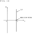
- FIG. 16 is a diagram illustrating a range on a complex plane within which an ideal demodulation vector is present when a pilot signal including only a real-axis component having an amplitude value of "1" is received and demodulated under the environment that no variation or noise is present in a transmission channel in OFDM/OQAM.
- an ideal demodulation vector of a pilot signal including only a real-axis component having an amplitude value of "1" is present anywhere on a straight line L0 of FIG. 16 and is not uniquely fixed.
- the ideal demodulation vector of the pilot signal has an uncertain imaginary-axis component caused by an interference from an OFDM/OQAM multicarrier modulation signal which is not known to a receiver for preceding and succeeding symbols and adjacent subcarriers, and therefore, is not uniquely fixed. Therefore, the receiver cannot obtain the amount of a change between the ideal demodulation vector of the pilot signal and a demodulation vector of an actually received pilot signal, as is similar to OFDM/QAM, so that transmission channel characteristics cannot be correctly estimated.
- Patent Documents 1 and 2 Methods for estimating transmission channel characteristics in OFDM/OQAM, which solves the problem, have been proposed in, for example, Patent Documents 1 and 2.
- Patent Document 1 In conventional multicarrier modulation disclosed in Patent Document 1, three methods for estimating transmission channel characteristics are described.
- a continuous pilot signal is used which is obtained by modulating all subcarriers over 2K-1 symbols (K represents an overlapping symbol number) with the same pilot signal.
- Patent Document 1 the first method of Patent Document 1 will be described.
- FIGS. 17A and 17B are conceptual diagrams illustrating a pilot signal in the first method of Patent Document 1.
- FIG. 17A illustrates a portion of a frame format used in the first method.
- FIG. 17B is a schematic diagram illustrating a relationship in frequency between spectrum of pilot signals and subcarriers.
- the horizontal axis represents an arrangement of subcarriers in a frequency direction
- the vertical axis represents an arrangement of symbols in a time direction.
- a continuous pilot signal is obtained by modulating all subcarriers over 2K-1 symbols with the same pilot signal.
- FIG. 17B the horizontal axis represents frequencies and the vertical axis represents spectral intensities.
- Spectrum of the continuous pilot signal appear as emission line spectrum between subcarrier modulation spectrum.
- FIG. 17B illustrates, for example, only spectrum fp1 to fp3 of the continuous pilot signal.
- the reason why the frequency relationship between the spectrum of the continuous pilot signal and the subcarrier modulation spectrum is what is illustrated in FIG. 17B is that, since the continuous pilot signal is composed of the same pilot signal which is repeated in the time intervals Ts, the spectrum of the continuous pilot signal repeatedly appear at intervals of 1/Ts on the frequency axis, while the frequency interval of the subcarrier modulation spectrum is 1/(2Ts).
- the K-th symbol and thereafter of the continuous pilot signal constitute a section in which there is no overlap with an unknown OFDM/OQAM multicarrier modulation signal in preceding and succeeding receivers. Therefore, in the ideal demodulation vectors of the pilot signals included in the continuous pilot signal, no interference occur in the uncertain imaginary-axis direction due to the unknown OFDM/OQAM multicarrier modulation signal in the receiver, so that the ideal demodulation vector of the pilot signal is fixed to a single known point in the receiver. Therefore, in the first method of Patent Document 1, by calculating the amount of a change between a known ideal demodulation vector and a demodulation vector of an actually received pilot signal in the receiver, transmission channel characteristics are estimated.
- FIG. 18 is a conceptual diagram illustrating a method for estimating transmission channel characteristics in the first method of Patent Document 1.
- an ideal demodulation vector (a point A) of a pilot signal and a demodulation vector (a point B) of an actually received pilot signal are illustrated on a complex plane. Since the ideal demodulation vector of the pilot signal is fixed to the single point A, the amount of a change between the ideal demodulation vector and the demodulation vector of the actually received pilot signal can be calculated.
- the ideal demodulation vector of a pilot signal is fixed to a single point, so that transmission channel characteristics can be estimated.
- FIG. 19 is a diagram illustrating a portion of a frame format used in the second method.
- the horizontal axis represents an arrangement of subcarriers in the frequency direction
- the vertical axis represents an arrangement of symbols in the time direction.
- a short continuous pilot signal is used which is obtained by modulating all subcarriers over one or more and less than 2K-1 symbols (three symbols in FIG. 19 ) with a pilot signal.
- the short continuous pilot signal having a time corresponding to one or more and less than 2K-1 symbols overlaps an unknown OFDM/OQAM multicarrier modulation signal, which presents in preceding and succeeding of the short continuous pilot signal, in a receiver in any section. Therefore, the ideal demodulation vector of the pilot signal is invariably interfered with by an uncertain imaginary-axis component due to preceding and succeeding OFDM/OQAM multicarrier modulation signals. Therefore, the ideal demodulation vector of the pilot signal is not fixed to a single point, and therefore, is unknown to a receiver. Therefore, in the second method, by utilizing the fact that two adjacent subcarriers have substantially the same transmission channel characteristics, transmission channel characteristics are estimated based on the ideal demodulation vectors of pilot signals of two adjacent subcarriers at the same time.
- FIG. 20 is a conceptual diagram illustrating a method for estimating transmission channel characteristics in the second method of Patent Document 1.
- a signal point which is obtained from a demodulation vector in an m-th subcarrier (any one subcarrier in FIG. 19 ) is represented by a point Rm
- a signal point which is obtained from a demodulation vector in an(m+1)-th subcarrier adjacent to the m-th subcarrier is represented by a point Rm+1.
- FIG. 20 represents a line connecting two signal points which are obtained from the ideal demodulation vectors of pilot signals obtained by demodulating pilot carriers of the m-th subcarrier and the (m+1)-th subcarrier when there is no variation or noise in a transmission channel.
- a straight line extending through the point Rm and the point Rm+1 is indicated by L1
- an intersection point of a perpendicular line dropped from the origin O to the straight line L1 and the straight line L1 is indicated by P.
- a distance between demodulation vectors of two pilot signals may be small.
- a demodulation error between the points Rm and Rm+1 has a significant influence on the slope of the straight line L1, so that, particularly, the precision of estimation of the amount of a change in phase is deteriorated. Therefore, in the second method, the numbers of repetitions of a pilot symbol is increased, thereby increasing the distance between demodulation vectors of two pilot signals.
- the influence of overlapping of an unknown OFDM/OQAM multicarrier modulation signal in a receiver becomes smaller.
- the spectrum of a short continuous pilot signal of one or more and less than 2K-1 symbols is close to an emission line spectrum having a component at an intermediate frequency between two subcarrier modulation spectrum. Therefore, an interference from an OFDM/OQAM multicarrier modulation signal of an adjacent subcarrier is reduced. Therefore, the influence of the demodulation error between the point Rm and the point Rm+1 on the slope of the straight line L1 is reduced, resulting in an improvement in the precision of estimation of transmission channel characteristics.
- a transmission channel can be estimated based on demodulation vectors of pilot signals of two adjacent subcarriers at the same time. Also, by increasing the numbers of repetitions of a pilot signal to increase the distance between demodulation vectors of two pilot signals, the precision of estimation of a transmission channel is improved.
- a short continuous pilot signal is used which is obtained by modulating all subcarriers over two or more and less than 2K-1 symbols with a pilot signal.
- transmission channel characteristics are estimated based on the demodulation vectors of two successive pilot signals in the time direction in the same subcarrier. In this case, although the number of repetitions of a pilot signal needs to be two or more, transmission channel characteristics can be estimated based on pilot signals of two successive symbols in the same subcarrier.
- a transmission channel can be estimated based on demodulation vectors of pilot signals of two successive symbols in the same subcarrier.
- Patent Document 2 will be described.
- Patent Document 2 two adjacent subcarriers are successively modulated with the same pilot signal.
- FIGS. 21A and 21B are conceptual diagrams illustrating pilot signals in Patent Document 2.
- FIG. 21A is a diagram illustrating a portion of a frame format.
- FIG. 21B is a schematic diagram illustrating a relationship in frequency between spectrum of pilot signals and subcarriers.
- the horizontal axis represents an arrangement of subcarriers in the frequency direction
- the vertical axis represents an arrangement of symbols in the time direction.
- each pilot carrier includes two adjacent subcarriers, and the pilot carriers are successively modulated with the same known data.
- the horizontal axis represents frequencies
- the vertical axis represents spectral intensities.
- Spectrum fp1 and fp2 of pilot signals appear as emission line spectrum each of which is located at a middle between two adjacent subcarrier modulation spectrum.
- the ideal demodulation vector of the pilot signal is fixed to substantially a single point, and is known to a receiver. Therefore, in Patent Document 2, as is similar to the transmission channel characteristics estimation method of FIG. 18 in the first method of Patent Document 1, the amount of a change between the ideal demodulation vector of the pilot signal which is known to a receiver and a demodulation vector of an actually received pilot signal is calculated to estimate transmission channel characteristics.
- an adjacent subcarrier of a pilot carrier is assigned as a mask carrier and is not used for data transmission.
- the mask carrier an interference from a data transmission signal which occurs in the pilot signal is suppressed, the ideal demodulation vector of the pilot signal is more correctly fixed to a single point, and the precision of estimation of transmission channel characteristics is improved.
- each pilot carrier including two subcarriers is assigned, and the pilot carriers are successively modulated with the same known data, or further, by assigning an adjacent subcarrier of a pilot carrier as a mask carrier, the ideal demodulation vector of the pilot signal can be fixed to substantially a single point, so that transmission channel characteristics can be estimated.
- the frequency efficiency is improved, but the precision of estimation of transmission channel characteristics is reduced and there is a large variation in the estimated value and there is also a large error. Also, in order to prevent the deterioration of the precision of estimation of transmission channel characteristics due to the small distance between the ideal demodulation vectors of two adjacent subcarriers, it is necessary to increase the number of repetitions of a pilot symbol, the frequency efficiency is reduced as is similar to the first method of Patent Document 1.
- pilot carriers each of which includes two adjacent subcarriers.
- the number of pilot carriers, which cannot be used for data transmission be small.
- the transmission channel estimation method in the second method of Patent Document 1 and the frame format of Patent Document 2 may be combined.
- the frame format pilot carriers each of which includes two adjacent subcarriers are used as in FIG. 21A , and the same known data is inserted into the pilot carriers successively.
- the transmission channel estimation method as in FIG. 20 , transmission channel characteristics are estimated based on demodulation vectors of pilot signals of two adjacent subcarriers.
- an object of the present invention is to estimate the transmission channel characteristics using a pilot carrier with a high level of frequency efficiency and a high level of precision of estimation of transmission channel characteristics in the OFDM/OQAM multicarrier modulation scheme.
- a multicarrier modulation scheme of the present invention modulates a single subcarrier with a pilot signal in a transmitter to generate a pilot carrier, and transmits an OFDM/OQAM multicarrier modulation signal. Also, in a receiver, the OFDM/OQAM multicarrier modulation signal is demodulated, and based two successive demodulation vectors in a time direction which are obtained by demodulating the pilot carrier, transmission channel characteristics are estimated and corrected.
- the number of subcarriers used as pilot carriers is one, so that the frequency efficiency can be improved.
- the distance between the ideal demodulation vectors of pilot signals of two successive symbols in the time direction can be maximized, the precision of estimation of transmission channel characteristics can be improved.
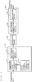
- FIG. 1 is a diagram illustrating a configuration of a communication system employing multicarrier modulation according to a first embodiment of the present invention.
- a transmitter 110 and a receiver 130 are connected to each other via a transmission channel 120.
- a multicarrier signal emitted by the transmitter 110 is received by the receiver 130 via the transmission channel 120.
- the transmission channel 120 is a wired channel or a wireless channel.
- the transmission channel 120 is a wireless channel, transmission from the transmitter 110 to the transmission channel 120 and from the transmission channel 120 to the receiver 130 is performed via an antenna (not shown).
- the transmitter 110 includes a pilot signal sequence generating section 113, a modulation signal generating section 111, and a multicarrier modulating section 112.
- the pilot signal sequence generating section 113 generates a cyclic pilot signal sequence using a reference pilot signal sequence described below.
- the modulation signal generating section 111 performs amplitude modulation based on input transmission data to generate a transmission data signal sequence (baseband signal), and inserts the cyclic pilot signal output by the pilot signal sequence generating section 113 into the transmission data signal sequence to generate a modulation signal.
- the multicarrier modulating section 112 receives and subjects the modulation signal generated by the modulation signal generating section 111 to OFDM/OQAM multicarrier modulation to generate an OFDM/OQAM multicarrier modulation signal.
- the OFDM/OQAM multicarrier modulation signal is transmitted via the transmission channel 120 to the receiver 130.
- the receiver 130 includes a multicarrier demodulating section 131 and an equalization section 132.
- the multicarrier demodulating section 131 subjects the received OFDM/OQAM multicarrier modulation signal to OFDM/OQAM multicarrier demodulation to generate a demodulation vector.
- the equalization section 132 receives the demodulation vector generated by the multicarrier demodulating section 131, and based on demodulation vectors of two successive pilot signals in a time direction, estimates and compensates for transfer characteristics of the transmission channel 120.
- FIG. 2 is a diagram illustrating a detailed configuration of the receiver 130.
- the multicarrier demodulating section 131 includes demodulation filters 133 provided for respective subcarriers (indicated by Filter 1 to Filter M in FIG. 2 ) and down samplers 134 (indicated by ⁇ in FIG. 2 ).
- the demodulation filter 133 receives the OFDM/OQAM multicarrier modulation signal and outputs a demodulation signal per sample.
- the down sampler 134 receives the demodulation signals output by the demodulation filter 133, extracts only a demodulation signal(s) at symbol timing, and outputs the extracted signal as a demodulation vector.
- the equalization section 132 includes a pilot signal extracting section 141, a transmission channel characteristics estimating section 145, and an amplitude and phase compensating section 144.
- the transmission channel characteristics estimating section 145 includes a delay section 142 (indicated by Z -1 in FIG. 2 ) and an amplitude and phase change amount estimating section 143.
- the pilot signal extracting section 141 receives demodulation vectors output by the multicarrier demodulating section 131, extracts only a demodulation vector (s) which is obtained by demodulating a pilot signal, and outputs the extracted signal as a pilot signal demodulation vector.
- the transmission channel characteristics estimating section 145 receives the pilot signal demodulation vector output by the pilot signal extracting section 141, and estimates the amounts of changes in amplitude and phase which represent transfer characteristics of the transmission channel 120.
- the delay section 142 receives the pilot signal demodulation vector output by the pilot signal extracting section 141, and outputs a delayed pilot signal demodulation vector which is delayed by a one-symbol time interval, i.e., Ts.
- the amplitude and phase change amount estimating section 143 estimates the amplitude and phase change amounts indicating the transfer characteristics of the transmission channel 120 based on the pilot signal demodulation vector output by the pilot signal extracting section 141 and the delayed pilot signal demodulation vector output by the delay section 142.
- the amplitude and phase compensating section 144 compensates for an amplitude and a phase of the demodulation vector output by the multicarrier demodulating section 131 based on the amplitude and phase change amounts estimated by the amplitude and phase change amount estimating section 143, and outputs the result as reception data from the equalization section 132.
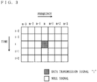
- the vertical axis represents an arrangement of symbols in the time direction
- the horizontal axis represents an arrangement of subcarriers in the frequency direction.
- a data transmission signal "1" is inserted only in a t-th symbol and an m-th subcarrier. Note that the OFDM/OQAM overlapping symbol number K is assumed as "2" in the following description.
- FIGS. 4A and 4B illustrate, as an example, a demodulation signal of the data transmission signal "1" which corresponds to the m-th subcarrier and is output from the demodulation filter 133, and a demodulation vector of the data transmission signal "1" which corresponds to the m-th subcarrier and is output from the down sampler 134.
- FIG. 4A is a diagram illustrating time responses of the demodulation signal and the demodulation vector.
- FIG. 4B is a diagram illustrating trajectories on a complex plane of the demodulation signal and the demodulation vector.
- the horizontal axis represents times and the vertical axis represents amplitudes. As can be seen from FIG.
- FIGS. 5A and 5B illustrate, as an example, a demodulation signal of the data transmission signal "1" which corresponds to an (m+1)-th subcarrier and is output from the demodulation filter 133, and a demodulation vector of the data transmission signal "1" which corresponds to the (m+1)-th subcarrier and is output from the down sampler 134.
- FIG. 5A is a diagram illustrating time responses of the demodulation signal and the demodulation vector.
- FIG. 5B is a diagram illustrating trajectories of the demodulation signal and the demodulation vector on a complex plane.
- the horizontal axis represents times and the vertical axis represents amplitudes.
- the trajectory of the demodulation vector has only imaginary-axis components at all symbol timings.
- a data transmission signal inserted in a subcarrier interferes with an adjacent subcarrier, and the interference components all occur in imaginary-axis components. Therefore, the occurring interference components in the frequency direction do not have an influence on the real-axis component of the demodulation symbol of the OFDM/OQAM modulation signal of an adjacent subcarrier.
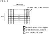
- FIG. 6 is a diagram illustrating a portion of a frame format in the multicarrier modulation scheme of the first embodiment of the present invention.
- the horizontal axis represents an arrangement of subcarriers in the frequency direction
- the vertical axis represents an arrangement of symbols in the time direction.
- a single subcarrier is modulated with a pilot signal to generate a pilot carrier.
- the pilot signal is obtained by cycling a reference pilot signal sequence which has a cycle of four and is composed of ⁇ , ⁇ , - ⁇ , - ⁇ (note that ⁇ is a real number of 0 or more) X times (X is a real number of 1 or more which becomes a natural number when it is multiplied by 4).
- the pilot signal is hereinafter referred to as a cyclic pilot signal sequence.
- the cyclic pilot signal sequence takes any value of ⁇ , ⁇ , - ⁇ , - ⁇ , ⁇ , ⁇ , - ⁇ , - ⁇ , ⁇ , - ⁇ , - ⁇ , ⁇ , ⁇ , - ⁇ , - ⁇ , ⁇ , ⁇ , - ⁇ , - ⁇ , ⁇ , ⁇ - ⁇ , - ⁇ , ⁇ , ⁇ , ⁇ , - ⁇ , - ⁇ , ⁇ , ⁇ , ⁇ , ⁇ , and ⁇ - ⁇ , ⁇ , - ⁇ , - ⁇ , ⁇ , ⁇ , - ⁇ .
- the cyclic pilot signal sequence takes any value of ⁇ , ⁇ , - ⁇ , - ⁇ , ⁇ , ⁇ , ⁇ , - ⁇ , - ⁇ , ⁇ , ⁇ , - ⁇ , ⁇ , ⁇ , - ⁇ , ⁇ - ⁇ , - ⁇ , ⁇ , ⁇ , - ⁇ , - ⁇ , and ⁇ - ⁇ , ⁇ , ⁇ , - ⁇ , - ⁇ , ⁇ .
- the reference pilot signal sequence is "+1, +1, -1, -1"
- the OFDM/OQAM overlapping symbol number K is "2".
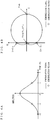
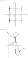
- a portion (a) of FIG. 7 is a diagram illustrating a demodulation vector on a complex plane of a pilot signal inserted in each symbol for each symbol timing, in a subcarrier used as a pilot carrier.
- a portion (b) of FIG. 7 is a diagram illustrating the resultant vector on a complex plane of demodulation vectors of pilot signals observed at symbol timings.
- the vertical axis represents pilot signals inserted in pilot carriers
- the horizontal axis represents times of symbol timings.
- T the trajectory of a demodulation vector of a pilot signal inserted in each symbol starts from the origin, rotates anti-clockwise, and returns to the origin, as in FIG. 4B .
- the resultant vector of demodulation vectors of pilot signals observed at symbol timings has a value obtained by adding demodulation vectors at the same symbol timing of the separate time responses of the symbols in the portion (a) of FIG. 7 .
- Ideal demodulation vectors of the cyclic pilot signal sequence repeatedly appear, on the complex plane, (1, -1) ⁇ (1, 1) ⁇ (-1, 1) ⁇ (-1, -1). Taking it into consideration that the time response of the cyclic pilot signal sequence of each symbol has the trajectory of FIG. 4B , it will be understood that a distance between demodulation vectors of pilot signals in two successive symbols is maximuized.
- FIG. 8 is a schematic diagram illustrating a relationship in frequency between spectrum of pilot signals and subcarriers.
- a spectrum fp1 of a pilot signal appears a center frequency of a subcarrier Pc1
- a spectrum fp2 of a pilot signal appears a center frequency of a subcarrier Pc2. Since the cyclic pilot signal sequence is composed of repetitions of the reference pilot signal sequence with a cycle of four (the time-axis cycle is 4Ts), the spectrum appears at a frequency of 1/(4Ts).
- OFDM/OQAM subcarriers have a frequency interval of 1/(2Ts) and are each provided at a location shifted by 1/(4Ts) from the center frequency of a corresponding subcarrier. Therefore, the spectrum of the cyclic pilot signal sequence coincide with the center frequencies of the OFDM/OQAM subcarriers.
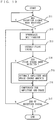
- FIG. 9 is a flowchart illustrating an operation of a transmitter which employs the multicarrier transmission method of the first embodiment of the present invention.
- step S201 it is determined whether or not there is a request for interruption of the transmitter. If there is no request for interruption of the transmitter, then it is determined whether or not there is an input of transmission data (step S202).
- a cyclic pilot signal sequence including a reference pilot signal sequence represented by any of amplitude modulation vectors ⁇ , ⁇ , - ⁇ , - ⁇ , ⁇ , - ⁇ , - ⁇ , ⁇ , ⁇ - ⁇ , ⁇ , ⁇ , - ⁇ , and ⁇ - ⁇ , - ⁇ , ⁇ , ⁇ using the real number ⁇ excluding 0 is generated (step S203).
- step S204 the generated cyclic pilot signal sequence is inserted into a transmission data signal sequence to generate a frame signal.
- the generated frame signal is subjected to multicarrier modulation and the result is transmitted (step S205) .
- steps S202 to S205 are repeatedly performed until there is a request for interruption of the transmitter.
- FIG. 10 is a flowchart illustrating an operation of a receiver which employs the multicarrier transmission method of the first embodiment of the present invention.
- step S211 it is determined whether or not a multicarrier modulation signal transmitted by a transmitter has been detected. If a multicarrier modulation signal has been detected, then the multicarrier modulation signal is demodulated to generate a demodulation vector (step S212). Next, a demodulation vector corresponding to a pilot carrier is extracted as a pilot signal demodulation vector from the generated demodulation vectors (step S213). Thereafter, it is determined whether or not a pilot signal demodulation vector has been extracted (step S214) .
- step S215 If a pilot signal demodulation vector has been extracted, amplitude and phase change amounts indicating transmission channel characteristics are estimated from the pilot signal demodulation vector (step S215), and based on the estimated amplitude and phase change amounts, the amplitude and phase of the demodulation vector are compensated for (step S216). On the other hand, if a pilot signal demodulation vector has not been extracted, the amplitude and phase of the demodulation vector are compensated for without estimation of amplitude and phase change amounts (step S216).
- the spectrum of the cyclic pilot signal sequence have the center frequencies of the OFDM/OQAM subcarriers
- the spectrum of a pilot carrier has a frequency which is most distant from the center frequency of the adjacent subcarrier, and therefore, the pilot carrier is unlikely to suffer from an interference component of an OFDM/OQAM modulation signal of its adjacent subcarrier. Therefore, as in the frame format of FIG. 6 , even if a data transmission signal of a subcarrier adjacent to a pilot carrier is present, it is possible to suppress an imaginary-axis direction interference component from occurring in a demodulation vector of a pilot signal.
- FIG. 11 is a diagram illustrating a range on a complex plane within which an ideal demodulation vector of a pilot signal is present in the first embodiment of the present invention.
- an interference component from a data carrier adjacent to a pilot carrier is present in the imaginary-axis direction, but the interference component is small and appears around the ideal demodulation vector, so that the distance between demodulation vectors of pilot signals of symbols can be held at the maximum level.
- FIG. 12 is a schematic diagram illustrating the transmission channel estimation method of the first embodiment of the present invention.
- a signal point obtained from a demodulation vector of a (t-1)-th symbol in a pilot carrier fp1 is assumed to be a point Rt-1
- a signal point obtained from a demodulation vector of a t-th symbol in the pilot carrier fp1 is assumed to be a point Rt.
- a straight line L2 indicates a range within which the demodulation vectors of the (t-1)-th and t-th pilot signals are present when there is no variation or noise of a transmission channel. As in FIG.
- a straight line L3 is drawn through the point Rt-1 and the point Rt, and an intersection point of a perpendicular line dropped from the origin O to the straight line L3 and the straight line L3 is indicated by P.
- a distance r between the point P and the origin O and an angle ⁇ between the I axis and the line segment OP are obtained, thereby making it possible to detect a phase difference and an amplitude difference, and estimate and correct transmission channel characteristics, errors in frequency and phase between a transmitter and a receiver, or the like.
- the distance between demodulation vectors of pilot signals of two successive symbols is invariably large. Therefore, it is possible to reduce an influence of a demodulation error of a pilot signal on the slope of the straight line L3, resulting in an improvement in the precision of estimation of transmission channel characteristics. Further, since the distance between demodulation vectors of pilot signals is invariably large, a variation in estimated value of transmission channel characteristics calculated for each symbol is small, and an error can be reduced.
- a single subcarrier is modulated with a pilot signal in a transmitter to generate a pilot carrier, so that transmission channel characteristics, errors in frequency and phase between the transmitter and a receiver, and the like can be estimated and corrected.
- the number of subcarriers required as pilot carriers is one, so that a communication system having a high level of frequency efficiency can be achieved.
- a real number ⁇ which is more than 0 and is known to a receiver is used, and a cyclic pilot signal sequence obtained by cycling a reference pilot signal sequence composed of any of amplitude modulation vectors ⁇ , ⁇ , - ⁇ , - ⁇ , ⁇ , - ⁇ , - ⁇ , ⁇ , ⁇ - ⁇ , ⁇ , ⁇ , - ⁇ , and ⁇ - ⁇ , - ⁇ , ⁇ , ⁇ , ⁇ once or more is used. Therefore, not only the spectrum are caused to be emission line spectrum having frequencies equal to center frequencies of subcarriers, but also it is possible to reduce an error occurring when the slope of a straight line connecting between demodulation vectors of pilot signals of two successive symbols is obtained, resulting in an improvement in the precision of estimation of transmission channel characteristics.
- the OFDM/OQAM overlapping symbol number K is two
- the same cyclic pilot signal sequence can be applied to a case where the overlapping symbol number K is more than two. This is because, even when the overlapping symbol number K is more than two, phases to be modulated between symbols adjacent to each other are caused to be different by ⁇ /2 radians, and due to this feature of OFDM/OQAM, ideal demodulation vectors of pilot signals become similar, and in addition, even when K>2, the amount of an interference of an imaginary-axis component generated from a symbol more distant than preceding and succeeding symbols is small.
- the reference pilot signal sequence used in the first embodiment may be "-1, +1, +1, -1", “-1, -1, +1, +1", or "+1, -1, -1, +1" as well as “+1, +1, -1, -1”.
- the cyclic sequence when a cyclic pilot signal sequence is generated, the cyclic sequence may have positive, positive, negative and negative signs in this order.
- ELT is a type of lapped orthogonal transform as OFDM/OQAM
- LOT Lapped Orthogonal Transform
- MLT Modulated Lapped Transform
- GenLOT Generalized Lapped Orthogonal Transform
- FIG. 13 is a diagram illustrating a portion of a frame format in a multicarrier modulation scheme according to a second embodiment of the present invention.
- the horizontal axis represents an arrangement of subcarriers in the frequency direction
- the vertical axis represents an arrangement of symbols in the time direction.
- an OFDM/OQAM multicarrier modulation signal is used in which a cycle of reference pilot signal sequence is inserted in a predetermined subcarrier.
- a transmission channel can be estimated based on the demodulation vectors of the pilot signals of the second and third symbols.
- a pilot signal required for estimation of a transmission channel can be constructed using a cycle of reference pilot signal sequence, resulting in a further increase in frequency efficiency.
Landscapes
- Engineering & Computer Science (AREA)
- Signal Processing (AREA)
- Computer Networks & Wireless Communication (AREA)
- Power Engineering (AREA)
- Digital Transmission Methods That Use Modulated Carrier Waves (AREA)
- Cable Transmission Systems, Equalization Of Radio And Reduction Of Echo (AREA)
Claims (11)
- Orthogonalfrequenzmultiplex (OFDM)-Offsetquadraturamplitudenmodulation (OQAM)-Mehrträger-Sendeverfahren, in dem eine Vielzahl von Subträgern, die eine Beziehung vτ=1/2 aufweisen, wobei τ ein Symbolintervall wiedergibt und v ein Frequenzintervall wiedergibt, einer Amplitudenmodulation unterworfen werden, wobei das Verfahren umfasst.
einen Sendeschritt zum Erzeugen und Senden eines Pilotträgers, der durch das Modulieren eines einzelnen Subträgers aus der Vielzahl von Subträgern mit einer Signalsequenz erhalten wird, die eine Referenzpilotsignalsequenz enthält, die durch beliebige Amplitudenmodulationsvektoren {α, α, -α, -α}, {α, -α, -α, α}, {-α, α, α, -α} und {-α, -α, α, α} wiedergegeben wird, wobei α eine reelle Zahl ungleich 0 wiedergibt, und
einen Schätzschritt zum Schätzen von Sendekanaleigenschaften basierend auf zwei aufeinander folgenden Pilotsignaldemodulationsvektoren in einer Zeitrichtung, die durch das Demodulieren des Pilotträgers erhalten werden. - Mehrträger-Sendeverfahren nach Anspruch 1, wobei der Sendeschritt umfasst:einen Erzeugungsschritt zum Erzeugen einer Pilotsignalsequenz, die eine Referenzpilotsignalsequenz enthält, die durch beliebige Amplitudenmodulationsvektoren {α, α, -α, -α}, {α, -α, -α, α}, {-α, α, α, -α} und {-α, -α, α, α} wiedergegeben wird, wobei α eine reelle Zahl ungleich 0 wiedergibt,einen Zusammenstellungsschritt zum Zusammenstellen eines Rahmensignals durch das Einfügen der Pilotsignalsequenz in eine Sendungsdatensignalsequenz, undeinen Modulations-/Sendeschritt zum Unterwerfen eines Zeitrahmensignals unter eine Mehrträgermodulation und zum Senden des Ergebnisses.
- Mehrträger-Sendeverfahren nach Anspruch 2, das weiterhin umfasst:einen Demodulationsschritt zum Demodulieren eines Mehrträgermodulationssignals, um einen Demodulationsvektor zu erzeugen,einen Extraktionsschritt zum Extrahieren eines Demodulationsvektors in Entsprechung zu dem Pilotträger als eines Pilotsignaldemodulationsvektors aus den Demodulationsvektoren,einen zweiten Schätzschritt zum Schätzen von Sendekanaleigenschaften aus dem Zeitpilotsignaldemodulationsvektor, undeinen Kompensationsschritt zum Kompensieren für den Demodulationsvektor basierend auf den in dem zweiten Schätzschritt geschätzten Sendekanaleigenschaften.
- Mehrträger-Sendeverfahren nach Anspruch 3, wobei der zweite Schätzschritt umfasst:einen Verzögerungsschritt zum Empfangen und Verzögern des Pilotsignaldemodulationsvektors um eine Symbolzeit, um einen verzögerten Pilotsignaldemodulationsvektor zu erzeugen, undeinen Änderungsgrößen-Schätzschritt zum Schätzen der Amplituden- und der Phasenänderungsgrößen, die Sendekanaleigenschaften angeben, basierend auf einem Differenzvektor zwischen dem Pilotsignaldemodulationsvektor und dem verzögerten Pilotsignaldemodulationsvektor,wobei der Kompensationsschritt für eine Amplitude und eine Phase des Demodulationsvektors basierend auf den Amplituden- und Phasenänderungsgrößen kompensiert.
- Mehrträger-Sendeverfahren nach Anspruch 2, wobei die Pilotsignalsequenz erzeugt wird durch das X-malige Durchlaufen der Referenzpilotsignalsequenz, wobei X eine reelle Zahl von 1 oder mehr, die bei einer Multiplikation mit 4 eine natürliche Zahl wird, wiedergibt.
- Orthogonalfrequenzmultiplex (OFDM)-Offsetquadraturamplitudenmodulation (OQAM)-Mehrträgermodulationssignal-Sendevorrichtung für das Senden eines Mehrträgermodulationssignals, das durch das Unterwerfen einer Vielzahl von Subträgern, die eine Beziehung vτ=1/2 aufweisen, wobei τ ein Symbolintervall wiedergibt und v ein Frequenzintervall wiedergibt, unter eine Amplitudenmodulation erhalten wird, wobei die Vorrichtung umfasst:
einen Pilotträger-Sendeabschnitt zum Erzeugen und Senden eines Pilotträgers, der durch das Modulieren eines einzelnen Subträgers aus der Vielzahl von Subträgern mit einer Signalsequenz erhalten wird, die eine Referenzpilotsignalsequenz enthält, die durch beliebige Amplitudenmodulationsvektoren {α, α, -α, -α}, {α, -α, -α, α}, {-α, α, α, -α} und {-α, -α, α, α} wiedergegeben wird, wobei α eine reelle Zahl ungleich 0 wiedergibt. - Mehrträgermodulationssignal-Sendevorrichtung nach Anspruch 6, wobei der Pilotträger-Sendeabschnitt umfasst:einen Pilotsignalsequenz-Erzeugungsabschnitt (113) zum Erzeugen einer Pilotsignalsequenz, die eine Referenzpilotsignalsequenz enthält, die durch beliebige Amplitudenmodulationsvektoren {α, α, -α, -α}, {α, -α, -α, α}, {-α, α, α, -α} und {-α, -α, α, α} wiedergegeben wird, wobei α eine reelle Zahl ungleich 0 wiedergibt,einen Rahmenzusammenstellungsabschnitt zum Zusammenstellen eines Rahmensignals durch das Einfügen der Pilotsignalsequenz in eine Sendedatensignalsequenz, undeinen Mehrträgermodulationssignal-Sendeabschnitt (112) zum Unterwerfen eines einzelnen Subträgers aus der Vielzahl von Subträgern unter eine Mehrträgermodulation mit dem Rahmensignal, um einen Zeitpilotträger zu erzeugen, und zum Senden des Pilotträgers.
- Mehrträgermodulationssignal-Sendevorrichtung nach Anspruch 7, wobei die Pilotsignalsequenz erzeugt wird durch das X-malige Durchlaufen der Referenzpilotsignalsequenz, wobei X eine reelle Zahl von 1 oder mehr, die bei einer Multiplikation mit 4 eine natürliche Zahl wird, wiedergibt.
- Orthogonalfrequenzmultiplex (OFDM)-Offsetquadraturamplitudenmodulation (OQAM)-Mehrträgermodulationssignal-Empfangsvorrichtung für das Empfangen eines Mehrträgermodulationssignals, das durch das Unterwerfen einer Vielzahl von Subträgern, die eine Beziehung vτ=1/2 aufweisen, wobei τ ein Symbolintervall wiedergibt und v ein Frequenzintervall wiedergibt, unter eine Amplitudenmodulation erhalten wird, wobei:
das Mehrträgermodulationssignal einen Pilotträger enthält, der durch das Modulieren eines einzelnen Subträgers aus der Vielzahl von Subträgern mit einer Signalsequenz erhalten wird, die eine Referenzpilotsignalsequenz enthält, die durch beliebige Amplitudenmodulationsvektoren {α, α, -α, -α}, {α, -α, -α, α}, {-α, α, α, -α} und {-α, -α, α, α} wiedergegeben wird, wobei α eine reelle Zahl ungleich 0 wiedergibt, wobei die Vorrichtung umfasst:
einen Sendekanaleigenschaften-Schätzabschnitt (145) zum Schätzen von Sendekanaleigenschaften basierend auf zwei aufeinander folgenden Pilotsignaldemodulationsvektoren in einer Zeitrichtung, die durch das Demodulieren des Pilotträgers erhalten werden. - Mehrträgermodulationssignal-Empfangsvorrichtung nach Anspruch 9, die weiterhin umfasst:einen Mehrträger-Demodulationsabschnitt (131) zum Demodulieren des Mehrträgermodulationssignals, um einen Demodulationsvektor zu erzeugen,einen Pilotsignal-Extraktionsabschnitt (141) zum Extrahieren eines Demodulationsvektors in Entsprechung zu dem Pilotträger als eines Pilotsignaldemodulationsvektors aus den Demodulationsvektoren,einen zweiten Sendekanaleigenschaften-Schätzabschnitt zum Schätzen von Sendekanaleigenschaften aus dem Pilotsignaldemodulationsvektor, undeinen Amplitude/Phase-Kompensationsabschnitt (144) zum Kompensieren für den Demmodulationsvektor basierend auf den in dem zweiten Sendekanaleigenschaften-Schätzabschnitt geschätzten Sendekanaleigenschaften.
- Mehrträgermodulationssignal-Empfangsvorrichtung nach Anspruch 10, wobei der zweite Sendekanaleigenschaften-Schätzabschnitt umfasst:einen Verzögerungsabschnitt (142) zum Empfangen und Verzögern des Pilotsignaldemodulationsvektors um eine Symbolzeit, um einen verzögerten Pilotsigaldemodulationsvektor zu erzeugen, undeinen Amplituden-/Phasenänderungsgrößen-Schätzabschnitt (143) zum Schätzen der Amplituden- und Phasenänderungsgrößen, die Sendekanaleigenschaften angeben, basierend auf einem Differenzvektor zwischen dem Pilotsignaldemodulationsvektor und dem verzögerten Pilotsignaldemodulationsvektor,wobei der Amplitudenphasen-Kompensationsabschnitt (144)füreine Amplitude und eine Phase des Demodulationsvektors basierend auf den Amplituden- und Phasenänderungsgrößen kompensiert.
Applications Claiming Priority (1)
| Application Number | Priority Date | Filing Date | Title |
|---|---|---|---|
| JP2006111759 | 2006-04-14 |
Publications (3)
| Publication Number | Publication Date |
|---|---|
| EP1845679A2 EP1845679A2 (de) | 2007-10-17 |
| EP1845679A3 EP1845679A3 (de) | 2013-03-06 |
| EP1845679B1 true EP1845679B1 (de) | 2018-12-26 |
Family
ID=38328310
Family Applications (1)
| Application Number | Title | Priority Date | Filing Date |
|---|---|---|---|
| EP07007592.4A Not-in-force EP1845679B1 (de) | 2006-04-14 | 2007-04-13 | Mehrträgersendeverfahren, Mehrträger-Modulationssignalsendevorrichtung, Mehrträger-Modulationssignalempfangsvorrichtung, Mehrträger-Modulationssignalsendeverfahren und Pilotsignalerzeugungsverfahren |
Country Status (2)
| Country | Link |
|---|---|
| US (1) | US7876842B2 (de) |
| EP (1) | EP1845679B1 (de) |
Families Citing this family (19)
| Publication number | Priority date | Publication date | Assignee | Title |
|---|---|---|---|---|
| JP4463723B2 (ja) * | 2005-04-28 | 2010-05-19 | 株式会社エヌ・ティ・ティ・ドコモ | 送信機及び送信方法 |
| US9100165B2 (en) * | 2005-06-27 | 2015-08-04 | John W. Bogdan | Direct data recovery |
| EP2146473B1 (de) * | 2008-07-15 | 2019-09-11 | ADTRAN GmbH | Verfahren und Vorrichtung zur Datenverarbeitung und Kommunikationssystem mit einer derartigen Vorrichtung |
| US9136891B2 (en) * | 2011-12-12 | 2015-09-15 | John W. Bogdan | Adaptive data decoding |
| US8416866B1 (en) * | 2009-07-30 | 2013-04-09 | Qualcomm Incorporated | System and method for reducing phase errors in multiple sub-carrier communication systems |
| FR2962812B1 (fr) * | 2010-07-19 | 2012-10-12 | Thales Sa | Dispositif d'antenne a ouverture synthetique de reception de signaux d'un systeme comprenant une porteuse et des moyens de determination de sa trajectoire |
| FR2985152A1 (fr) | 2011-12-23 | 2013-06-28 | France Telecom | Procede de groupement de couples emetteur-recepteur pour communiquer sur un reseau de communications |
| FR2985134A1 (fr) * | 2011-12-23 | 2013-06-28 | France Telecom | Procede d'emission d'au moins un signal multi-porteuse forme de symboles ofdm-oqam |
| CN104253680B (zh) * | 2013-06-27 | 2018-07-31 | 华为技术有限公司 | 一种fbmc系统中同步信号的发送方法和装置 |
| US9634720B2 (en) | 2013-07-05 | 2017-04-25 | Sony Corporation | Apparatuses and a method for crosstalk estimations |
| CN105814856B (zh) * | 2013-11-26 | 2019-02-12 | 普鲁斯恩公司 | 控制组合波形的方法、设备和系统、组合多个信号的设备 |
| CN106302301A (zh) * | 2015-06-24 | 2017-01-04 | 北京三星通信技术研究有限公司 | 基于复数调制的fbmc信号发送和接收的方法及其装置 |
| EP3434055B1 (de) * | 2016-03-23 | 2023-05-10 | Nokia Technologies Oy | Gemeinsamer phasenfehler und/oder zwischenträgerinterferenz |
| US10511388B1 (en) * | 2018-08-10 | 2019-12-17 | Fujitsu Limited | Reducing variance in reach of WDM channels in an optical network |
| WO2020110471A1 (ja) * | 2018-11-29 | 2020-06-04 | 日本電信電話株式会社 | 受信装置、受信方法及びプログラム |
| CN109818893B (zh) * | 2019-01-29 | 2020-07-10 | 华中科技大学 | 一种数据通信方法及通信设备 |
| CN114710383A (zh) * | 2022-03-31 | 2022-07-05 | 瑞玛思特(深圳)科技有限公司 | 一种利用ofdm信号对仪表射频通道频响进行校准的方法 |
| CN115001532B (zh) * | 2022-05-16 | 2023-06-27 | 重庆邮电大学 | 基于plc信道的跳频扩频调制解调方法 |
| CN116886135B (zh) * | 2023-09-04 | 2023-11-10 | 思腾合力(天津)科技有限公司 | 基于方向调制的多载波信号生成方法及装置 |
Family Cites Families (14)
| Publication number | Priority date | Publication date | Assignee | Title |
|---|---|---|---|---|
| US3511936A (en) * | 1967-05-26 | 1970-05-12 | Bell Telephone Labor Inc | Multiply orthogonal system for transmitting data signals through frequency overlapping channels |
| FI102340B (fi) * | 1997-01-16 | 1998-11-13 | Nokia Telecommunications Oy | Tiedonsiirtomenetelmä ja radiojärjestelmä |
| JPH1117760A (ja) * | 1997-06-24 | 1999-01-22 | Sony Corp | 受信装置及び送受信装置並びに通信方法 |
| US5987005A (en) * | 1997-07-02 | 1999-11-16 | Telefonaktiebolaget Lm Ericsson | Method and apparatus for efficient computation of discrete fourier transform (DFT) and inverse discrete fourier transform |
| FR2799597B1 (fr) * | 1999-10-08 | 2004-02-20 | Mitsubishi Electric Inf Tech | Procede de transmission de donnees sur porteuses multiples d'un emetteur a un recepteur et recepteur prevu pour la mise en oeuvre dudit procede |
| KR100325367B1 (ko) * | 2000-01-28 | 2002-03-04 | 박태진 | 직교 주파수 분할 다중 통신 시스템에서의 비트 오율 측정장치및 방법 |
| FR2814302B1 (fr) * | 2000-09-20 | 2003-02-07 | France Telecom | Signal multiporteuse a pilotes repartis concu pour limiter l'interference, procede de construction d'un signal, procede de reception, recepteur et dispositif d'emission correspondants |
| FR2814303A1 (fr) * | 2000-09-20 | 2002-03-22 | France Telecom | Signal multiporteuse a symbole de reference concu pour limiter l'interference, procede de reception, procede de construction, recepteur et dispositif correspondants |
| US7099266B2 (en) * | 2001-03-26 | 2006-08-29 | Victor Company Of Japan, Limited | Orthogonal frequency division multiplexed signal transmitting apparatus, orthogonal frequency division multiplexed signal receiving apparatus, and orthogonal frequency division multiplexed signal transmitting/receiving system |
| US7706458B2 (en) * | 2001-04-24 | 2010-04-27 | Mody Apurva N | Time and frequency synchronization in Multi-Input, Multi-Output (MIMO) systems |
| JP4047116B2 (ja) * | 2002-09-19 | 2008-02-13 | キヤノン株式会社 | 画像形成システム |
| JP4637498B2 (ja) | 2004-04-16 | 2011-02-23 | パナソニック株式会社 | 通信装置および通信方法 |
| JP2005311413A (ja) | 2004-04-16 | 2005-11-04 | Matsushita Electric Ind Co Ltd | 通信装置及び通信方法 |
| JP2006253980A (ja) * | 2005-03-10 | 2006-09-21 | Fujitsu Ltd | 受信方法および受信装置 |
-
2007
- 2007-04-09 US US11/783,377 patent/US7876842B2/en active Active
- 2007-04-13 EP EP07007592.4A patent/EP1845679B1/de not_active Not-in-force
Non-Patent Citations (1)
| Title |
|---|
| None * |
Also Published As
| Publication number | Publication date |
|---|---|
| EP1845679A3 (de) | 2013-03-06 |
| US20080159423A1 (en) | 2008-07-03 |
| US7876842B2 (en) | 2011-01-25 |
| EP1845679A2 (de) | 2007-10-17 |
Similar Documents
| Publication | Publication Date | Title |
|---|---|---|
| US7876842B2 (en) | Multicarrier transmission method, multicarrier modulation signal transmission apparatus, multicarrier modulation signal reception apparatus, multicarrier modulation signal transmission method, and pilot signal generation method | |
| US8179986B2 (en) | Multicarrier modulation scheme as well as transmission apparatus and reception apparatus using the scheme | |
| US20230216718A1 (en) | Methods and systems for generating a low peak-to-average power ratio (papr) data and reference signal | |
| KR100263372B1 (ko) | 직교분할대역 시스템의 간략 주파수 획득 방법 및 그 장치 | |
| KR101109506B1 (ko) | 주파수 오프셋 보상 방법 | |
| CA2327876C (en) | Echo phase offset correction in a multi-carrier demodulation system | |
| EP2720427A1 (de) | Schätzung von CFO auf Grundlage relativer Werte von Frequenzlinien im Zusammenhang mit benutzten Subträgern von empfangenen Präambelsymbolen für OFDM-Systeme | |
| EP2712139A1 (de) | Symbolzeitversatzkorrektur mittels Zwischenträgerinterferenzdetektion in einem OFDM-Empfänger | |
| US7406125B2 (en) | Method for initialization of per tone frequency domain equalizer (FEQ) through noise reduction for multi-tone based modems | |
| US8345791B2 (en) | Methods for transmitting and receiving a multicarrier signal comprising isolated pilots, corresponding devices and computer program products | |
| JP4838185B2 (ja) | マルチキャリア伝送方法、マルチキャリア変調信号送信装置、マルチキャリア変調信号受信装置、マルチキャリア変調信号送信方法、及びパイロット信号生成方法 | |
| Hassan et al. | Variable pilot channels estimation based on blocktype and comb-type pilot arrangement in OFDM system | |
| US8223865B2 (en) | Method for the blind estimation of OFDM signal parameters by adapted filtering | |
| Chen et al. | Iterative ML estimation for frequency offset and time synchronization in OFDM systems | |
| Jose et al. | Peak to average power ratio reduction and inter symbol interference cancellation of FBMC-OQAM signals | |
| KR20050046209A (ko) | 직교주파수 분할 다중 전송 안테나 시스템에서 시변채널의 채널 추정 방법 | |
| Singh | A DFT based channel estimation technique in orthogonal-frequency division-multiplexing (OFDM): A Review | |
| Woltering et al. | Comparison of general multi-carrier schemes in two way relaying channels | |
| KR100625075B1 (ko) | 복소 채널 송수신 시스템에 있어서의 효율적인 채널 추정방법 | |
| Favalli et al. | Estimation and mitigation of intercarrier interference for OFDM systems in multipath fading channels | |
| KR100226699B1 (ko) | 직교 주파수 분할 다중화 수신 시스템의 위상 추출 장치 | |
| KR100871870B1 (ko) | Ofdm 시스템을 위한 ola 장치 및 기법 | |
| Boshehba et al. | A modified blind deterministic carrier frequency offset estimator for OFDM systems | |
| Sarker et al. | Channel estimation using RF signal processor based on OFDM system | |
| Ribeiro et al. | Estimation of CFO and channels in phase-shift orthogonal pilot-aided OFDM systems with transmitter diversity |
Legal Events
| Date | Code | Title | Description |
|---|---|---|---|
| PUAI | Public reference made under article 153(3) epc to a published international application that has entered the european phase |
Free format text: ORIGINAL CODE: 0009012 |
|
| AK | Designated contracting states |
Kind code of ref document: A2 Designated state(s): AT BE BG CH CY CZ DE DK EE ES FI FR GB GR HU IE IS IT LI LT LU LV MC MT NL PL PT RO SE SI SK TR |
|
| AX | Request for extension of the european patent |
Extension state: AL BA HR MK YU |
|
| RAP1 | Party data changed (applicant data changed or rights of an application transferred) |
Owner name: PANASONIC CORPORATION |
|
| PUAL | Search report despatched |
Free format text: ORIGINAL CODE: 0009013 |
|
| AK | Designated contracting states |
Kind code of ref document: A3 Designated state(s): AT BE BG CH CY CZ DE DK EE ES FI FR GB GR HU IE IS IT LI LT LU LV MC MT NL PL PT RO SE SI SK TR |
|
| AX | Request for extension of the european patent |
Extension state: AL BA HR MK RS |
|
| RIC1 | Information provided on ipc code assigned before grant |
Ipc: H04L 5/00 20060101ALI20130131BHEP Ipc: H04L 27/26 20060101AFI20130131BHEP Ipc: H04L 25/02 20060101ALI20130131BHEP |
|
| 17P | Request for examination filed |
Effective date: 20130829 |
|
| RBV | Designated contracting states (corrected) |
Designated state(s): AT BE BG CH CY CZ DE DK EE ES FI FR GB GR HU IE IS IT LI LT LU LV MC MT NL PL PT RO SE SI SK TR |
|
| AKX | Designation fees paid |
Designated state(s): AT BE BG CH CY CZ DE DK EE ES FI FR GB GR HU IE IS IT LI LT LU LV MC MT NL PL PT RO SE SI SK TR |
|
| RAP1 | Party data changed (applicant data changed or rights of an application transferred) |
Owner name: PANASONIC INTELLECTUAL PROPERTY CORPORATION OF AME |
|
| RAP1 | Party data changed (applicant data changed or rights of an application transferred) |
Owner name: WI-FI ONE, LLC |
|
| STAA | Information on the status of an ep patent application or granted ep patent |
Free format text: STATUS: EXAMINATION IS IN PROGRESS |
|
| 17Q | First examination report despatched |
Effective date: 20170803 |
|
| GRAP | Despatch of communication of intention to grant a patent |
Free format text: ORIGINAL CODE: EPIDOSNIGR1 |
|
| STAA | Information on the status of an ep patent application or granted ep patent |
Free format text: STATUS: GRANT OF PATENT IS INTENDED |
|
| INTG | Intention to grant announced |
Effective date: 20180706 |
|
| GRAS | Grant fee paid |
Free format text: ORIGINAL CODE: EPIDOSNIGR3 |
|
| GRAA | (expected) grant |
Free format text: ORIGINAL CODE: 0009210 |
|
| STAA | Information on the status of an ep patent application or granted ep patent |
Free format text: STATUS: THE PATENT HAS BEEN GRANTED |
|
| AK | Designated contracting states |
Kind code of ref document: B1 Designated state(s): AT BE BG CH CY CZ DE DK EE ES FI FR GB GR HU IE IS IT LI LT LU LV MC MT NL PL PT RO SE SI SK TR |
|
| REG | Reference to a national code |
Ref country code: GB Ref legal event code: FG4D |
|
| REG | Reference to a national code |
Ref country code: CH Ref legal event code: EP |
|
| REG | Reference to a national code |
Ref country code: AT Ref legal event code: REF Ref document number: 1082943 Country of ref document: AT Kind code of ref document: T Effective date: 20190115 |
|
| REG | Reference to a national code |
Ref country code: DE Ref legal event code: R096 Ref document number: 602007057208 Country of ref document: DE |
|
| REG | Reference to a national code |
Ref country code: IE Ref legal event code: FG4D |
|
| PG25 | Lapsed in a contracting state [announced via postgrant information from national office to epo] |
Ref country code: LV Free format text: LAPSE BECAUSE OF FAILURE TO SUBMIT A TRANSLATION OF THE DESCRIPTION OR TO PAY THE FEE WITHIN THE PRESCRIBED TIME-LIMIT Effective date: 20181226 Ref country code: LT Free format text: LAPSE BECAUSE OF FAILURE TO SUBMIT A TRANSLATION OF THE DESCRIPTION OR TO PAY THE FEE WITHIN THE PRESCRIBED TIME-LIMIT Effective date: 20181226 Ref country code: FI Free format text: LAPSE BECAUSE OF FAILURE TO SUBMIT A TRANSLATION OF THE DESCRIPTION OR TO PAY THE FEE WITHIN THE PRESCRIBED TIME-LIMIT Effective date: 20181226 Ref country code: BG Free format text: LAPSE BECAUSE OF FAILURE TO SUBMIT A TRANSLATION OF THE DESCRIPTION OR TO PAY THE FEE WITHIN THE PRESCRIBED TIME-LIMIT Effective date: 20190326 |
|
| REG | Reference to a national code |
Ref country code: NL Ref legal event code: MP Effective date: 20181226 |
|
| REG | Reference to a national code |
Ref country code: LT Ref legal event code: MG4D |
|
| PG25 | Lapsed in a contracting state [announced via postgrant information from national office to epo] |
Ref country code: GR Free format text: LAPSE BECAUSE OF FAILURE TO SUBMIT A TRANSLATION OF THE DESCRIPTION OR TO PAY THE FEE WITHIN THE PRESCRIBED TIME-LIMIT Effective date: 20190327 Ref country code: SE Free format text: LAPSE BECAUSE OF FAILURE TO SUBMIT A TRANSLATION OF THE DESCRIPTION OR TO PAY THE FEE WITHIN THE PRESCRIBED TIME-LIMIT Effective date: 20181226 |
|
| REG | Reference to a national code |
Ref country code: AT Ref legal event code: MK05 Ref document number: 1082943 Country of ref document: AT Kind code of ref document: T Effective date: 20181226 |
|
| PG25 | Lapsed in a contracting state [announced via postgrant information from national office to epo] |
Ref country code: NL Free format text: LAPSE BECAUSE OF FAILURE TO SUBMIT A TRANSLATION OF THE DESCRIPTION OR TO PAY THE FEE WITHIN THE PRESCRIBED TIME-LIMIT Effective date: 20181226 |
|
| PG25 | Lapsed in a contracting state [announced via postgrant information from national office to epo] |
Ref country code: PL Free format text: LAPSE BECAUSE OF FAILURE TO SUBMIT A TRANSLATION OF THE DESCRIPTION OR TO PAY THE FEE WITHIN THE PRESCRIBED TIME-LIMIT Effective date: 20181226 Ref country code: IT Free format text: LAPSE BECAUSE OF FAILURE TO SUBMIT A TRANSLATION OF THE DESCRIPTION OR TO PAY THE FEE WITHIN THE PRESCRIBED TIME-LIMIT Effective date: 20181226 Ref country code: PT Free format text: LAPSE BECAUSE OF FAILURE TO SUBMIT A TRANSLATION OF THE DESCRIPTION OR TO PAY THE FEE WITHIN THE PRESCRIBED TIME-LIMIT Effective date: 20190426 Ref country code: CZ Free format text: LAPSE BECAUSE OF FAILURE TO SUBMIT A TRANSLATION OF THE DESCRIPTION OR TO PAY THE FEE WITHIN THE PRESCRIBED TIME-LIMIT Effective date: 20181226 Ref country code: ES Free format text: LAPSE BECAUSE OF FAILURE TO SUBMIT A TRANSLATION OF THE DESCRIPTION OR TO PAY THE FEE WITHIN THE PRESCRIBED TIME-LIMIT Effective date: 20181226 |
|
| PG25 | Lapsed in a contracting state [announced via postgrant information from national office to epo] |
Ref country code: RO Free format text: LAPSE BECAUSE OF FAILURE TO SUBMIT A TRANSLATION OF THE DESCRIPTION OR TO PAY THE FEE WITHIN THE PRESCRIBED TIME-LIMIT Effective date: 20181226 Ref country code: SK Free format text: LAPSE BECAUSE OF FAILURE TO SUBMIT A TRANSLATION OF THE DESCRIPTION OR TO PAY THE FEE WITHIN THE PRESCRIBED TIME-LIMIT Effective date: 20181226 Ref country code: IS Free format text: LAPSE BECAUSE OF FAILURE TO SUBMIT A TRANSLATION OF THE DESCRIPTION OR TO PAY THE FEE WITHIN THE PRESCRIBED TIME-LIMIT Effective date: 20190426 Ref country code: EE Free format text: LAPSE BECAUSE OF FAILURE TO SUBMIT A TRANSLATION OF THE DESCRIPTION OR TO PAY THE FEE WITHIN THE PRESCRIBED TIME-LIMIT Effective date: 20181226 |
|
| REG | Reference to a national code |
Ref country code: DE Ref legal event code: R097 Ref document number: 602007057208 Country of ref document: DE |
|
| PG25 | Lapsed in a contracting state [announced via postgrant information from national office to epo] |
Ref country code: AT Free format text: LAPSE BECAUSE OF FAILURE TO SUBMIT A TRANSLATION OF THE DESCRIPTION OR TO PAY THE FEE WITHIN THE PRESCRIBED TIME-LIMIT Effective date: 20181226 Ref country code: DK Free format text: LAPSE BECAUSE OF FAILURE TO SUBMIT A TRANSLATION OF THE DESCRIPTION OR TO PAY THE FEE WITHIN THE PRESCRIBED TIME-LIMIT Effective date: 20181226 |
|
| PLBE | No opposition filed within time limit |
Free format text: ORIGINAL CODE: 0009261 |
|
| STAA | Information on the status of an ep patent application or granted ep patent |
Free format text: STATUS: NO OPPOSITION FILED WITHIN TIME LIMIT |
|
| REG | Reference to a national code |
Ref country code: CH Ref legal event code: PL |
|
| 26N | No opposition filed |
Effective date: 20190927 |
|
| REG | Reference to a national code |
Ref country code: BE Ref legal event code: MM Effective date: 20190430 |
|
| PG25 | Lapsed in a contracting state [announced via postgrant information from national office to epo] |
Ref country code: MC Free format text: LAPSE BECAUSE OF FAILURE TO SUBMIT A TRANSLATION OF THE DESCRIPTION OR TO PAY THE FEE WITHIN THE PRESCRIBED TIME-LIMIT Effective date: 20181226 Ref country code: LU Free format text: LAPSE BECAUSE OF NON-PAYMENT OF DUE FEES Effective date: 20190413 |
|
| PG25 | Lapsed in a contracting state [announced via postgrant information from national office to epo] |
Ref country code: CH Free format text: LAPSE BECAUSE OF NON-PAYMENT OF DUE FEES Effective date: 20190430 Ref country code: LI Free format text: LAPSE BECAUSE OF NON-PAYMENT OF DUE FEES Effective date: 20190430 |
|
| PG25 | Lapsed in a contracting state [announced via postgrant information from national office to epo] |
Ref country code: SI Free format text: LAPSE BECAUSE OF FAILURE TO SUBMIT A TRANSLATION OF THE DESCRIPTION OR TO PAY THE FEE WITHIN THE PRESCRIBED TIME-LIMIT Effective date: 20181226 Ref country code: BE Free format text: LAPSE BECAUSE OF NON-PAYMENT OF DUE FEES Effective date: 20190430 |
|
| PG25 | Lapsed in a contracting state [announced via postgrant information from national office to epo] |
Ref country code: TR Free format text: LAPSE BECAUSE OF FAILURE TO SUBMIT A TRANSLATION OF THE DESCRIPTION OR TO PAY THE FEE WITHIN THE PRESCRIBED TIME-LIMIT Effective date: 20181226 |
|
| PG25 | Lapsed in a contracting state [announced via postgrant information from national office to epo] |
Ref country code: IE Free format text: LAPSE BECAUSE OF NON-PAYMENT OF DUE FEES Effective date: 20190413 |
|
| PG25 | Lapsed in a contracting state [announced via postgrant information from national office to epo] |
Ref country code: CY Free format text: LAPSE BECAUSE OF FAILURE TO SUBMIT A TRANSLATION OF THE DESCRIPTION OR TO PAY THE FEE WITHIN THE PRESCRIBED TIME-LIMIT Effective date: 20181226 |
|
| PG25 | Lapsed in a contracting state [announced via postgrant information from national office to epo] |
Ref country code: MT Free format text: LAPSE BECAUSE OF FAILURE TO SUBMIT A TRANSLATION OF THE DESCRIPTION OR TO PAY THE FEE WITHIN THE PRESCRIBED TIME-LIMIT Effective date: 20181226 Ref country code: HU Free format text: LAPSE BECAUSE OF FAILURE TO SUBMIT A TRANSLATION OF THE DESCRIPTION OR TO PAY THE FEE WITHIN THE PRESCRIBED TIME-LIMIT; INVALID AB INITIO Effective date: 20070413 |
|
| PGFP | Annual fee paid to national office [announced via postgrant information from national office to epo] |
Ref country code: FR Payment date: 20230425 Year of fee payment: 17 Ref country code: DE Payment date: 20230427 Year of fee payment: 17 |
|
| PGFP | Annual fee paid to national office [announced via postgrant information from national office to epo] |
Ref country code: GB Payment date: 20230427 Year of fee payment: 17 |
|
| REG | Reference to a national code |
Ref country code: DE Ref legal event code: R119 Ref document number: 602007057208 Country of ref document: DE |
|
| GBPC | Gb: european patent ceased through non-payment of renewal fee |
Effective date: 20240413 |
|
| PG25 | Lapsed in a contracting state [announced via postgrant information from national office to epo] |
Ref country code: DE Free format text: LAPSE BECAUSE OF NON-PAYMENT OF DUE FEES Effective date: 20241105 |
|
| PG25 | Lapsed in a contracting state [announced via postgrant information from national office to epo] |
Ref country code: GB Free format text: LAPSE BECAUSE OF NON-PAYMENT OF DUE FEES Effective date: 20240413 |
|
| PG25 | Lapsed in a contracting state [announced via postgrant information from national office to epo] |
Ref country code: FR Free format text: LAPSE BECAUSE OF NON-PAYMENT OF DUE FEES Effective date: 20240430 |
|
| PG25 | Lapsed in a contracting state [announced via postgrant information from national office to epo] |
Ref country code: GB Free format text: LAPSE BECAUSE OF NON-PAYMENT OF DUE FEES Effective date: 20240413 Ref country code: FR Free format text: LAPSE BECAUSE OF NON-PAYMENT OF DUE FEES Effective date: 20240430 Ref country code: DE Free format text: LAPSE BECAUSE OF NON-PAYMENT OF DUE FEES Effective date: 20241105 |