EP1844882A1 - Mold disassembly method and installation therefor - Google Patents
Mold disassembly method and installation therefor Download PDFInfo
- Publication number
- EP1844882A1 EP1844882A1 EP05816685A EP05816685A EP1844882A1 EP 1844882 A1 EP1844882 A1 EP 1844882A1 EP 05816685 A EP05816685 A EP 05816685A EP 05816685 A EP05816685 A EP 05816685A EP 1844882 A1 EP1844882 A1 EP 1844882A1
- Authority
- EP
- European Patent Office
- Prior art keywords
- tight
- truck
- flask
- drag
- level
- Prior art date
- Legal status (The legal status is an assumption and is not a legal conclusion. Google has not performed a legal analysis and makes no representation as to the accuracy of the status listed.)
- Granted
Links
Images





Classifications
-
- B—PERFORMING OPERATIONS; TRANSPORTING
- B22—CASTING; POWDER METALLURGY
- B22D—CASTING OF METALS; CASTING OF OTHER SUBSTANCES BY THE SAME PROCESSES OR DEVICES
- B22D29/00—Removing castings from moulds, not restricted to casting processes covered by a single main group; Removing cores; Handling ingots
- B22D29/04—Handling or stripping castings or ingots
-
- B—PERFORMING OPERATIONS; TRANSPORTING
- B22—CASTING; POWDER METALLURGY
- B22D—CASTING OF METALS; CASTING OF OTHER SUBSTANCES BY THE SAME PROCESSES OR DEVICES
- B22D33/00—Equipment for handling moulds
- B22D33/02—Turning or transposing moulds
-
- B—PERFORMING OPERATIONS; TRANSPORTING
- B22—CASTING; POWDER METALLURGY
- B22D—CASTING OF METALS; CASTING OF OTHER SUBSTANCES BY THE SAME PROCESSES OR DEVICES
- B22D33/00—Equipment for handling moulds
- B22D33/06—Burdening or relieving moulds
Definitions
- This invention relates to a method and a equipment for demolding.
- JP Y 59(1984)-1460 discloses a demolding method.
- a tight-flask cope is placed on a tight-flask drag, and molten metal is poured through a gate formed in the cope.
- a mold-drawing head, which is disposed above the cope is then lowered to draw the cope, the drag, and an as-cast product from the tight flasks, from above to below.
- the cope, drag, and the as-cast product fall, with the gate being located above and the as-cast product located below.
- the as-cast product tends to be subjected to dents due to the impact caused by the falling.
- the present invention has been conceived in view of that problem. It aims to provide a demolding method and a demolding equipment that can reduce the dents that may be formed in the as-cast product.
- a demolding method of the present invention includes the steps of placing a tight-flask cope on a tight-flask drag for mating, such that a gate for the tight-flask cope and drag faces upward, and of reversing the tight-flask cope and drag after the tight-flask cope and drag are poured with molten metal such that the gate faces downward; and drawing a cope, a drag, and an as-cast product from the reversed tight-flask cope and drag, with the gate facing downward, from above to below.
- Another aspect of the demolding method of the present invention includes the steps of placing a tight-flask cope on a tight-flask drag for mating, such that a gate for the tight-flask cope and drag faces upward, and of reversing the tight-flask cope and drag after the tight-flask cope and drag are poured with molten metal such that the gate faces downward; separating only the tight-flask drag, which has been reversed and thus located above, from the tight-flask cope, which has been reversed and thus located below the tight-flask drag, allowing an as-cast product and the downwardly facing gate to remain in the tight-flask cope; and drawing a cope, a drag, and the as-cast product from the reversed tight-flask cope and drag, from above to below.
- a further aspect of the demolding method of the present invention includes the steps of placing a tight-flask cope on a tight-flask drag for mating, such that a gate for the tight-flask cope and drag faces upward, and after the mated tight-flask cope and drag are poured with molten metal, transferring the mated tight-flask cope and drag placed on a lower level truck to a level-truck-mounting station; placing an upper level truck on the tight-flask cope and drag at the level-truck-mounting station such that the upper level truck faces the lower level truck; transferring the tight-flask cope and drag and the lower and upper level trucks from the level-truck-mounting station to a reversing station; reversing the tight-flask cope and drag and the upper and lower level trucks at the reversing station with the tight-flask cope and drag being sandwiched between the upper level truck and the lower level truck so that the upwardly facing gate faces downward;
- a further aspect of the demolding method of the present invention includes the steps of placing a tight-flask cope on a tight-flask drag for mating, such that a gate for the tight-flask cope and drag faces upward, and after the mated tight-flask cope and drag are poured with molten metal, transferring the mated tight-flask cope and drag placed on a lower level truck to a level-truck-mountuig station; placing an upper level truck on the tight-flask cope and drag at the level-truck-mounting station such that the upper level truck faces the lower level truck; transferring the tight-flask cope and drag and the lower and upper level trucks from the level-truck-mounting station to a reversing station; reversing the tight-flask cope and drag and the upper and lower level trucks at the reversing station with the tight-flask cope and drag being sandwiched between the upper level truck and the lower level truck so that the upwardly facing gate faces
- An aspect of the demolding equipment of the present invention includes a reversing means for reversing a tight-flask cope placed on a tight-flask drag for mating such that a gate for the tight-flask cope and drag faces upward, the mated tight-flask cope and drag being poured with molten metal, such that the gate faces downward; and a mold-drawing means for drawing a cope, a drag, and an as-cast product from the reversed tight-flask cope and drag, with the gate facing downward, from above to below.
- a further aspect of the demolding equipment of the present invention includes a reversing means for reversing a tight-flask cope placed on a tight-flask drag for mating such that a gate for the tight-flask cope and drag faces upward, the mated tight-flask cope and drag being poured with molten metal, such that the gate faces downward; a tight-flask drag-separating means for separating only the tight-flask drag, which has been reversed and thus located above, from the tight-flask cope, which has been reversed and thus located below the tight-flask drag, allowing an as-cast product and the downwardly facing gate to remain in the tight-flask cope; and drawing a cope, a drag, and the as-cast product from the reversed tight-flask cope and drag, from above to below.
- a further aspect of the demolding equipment of the present invention includes a level-truck-mounting means for placing an upper level truck on a opposing lower level truck on which mated tight-flask cope and drag are carried, with a gate for the tight-flask cope and drag facing upward, the mated tight-flask cope and drag being poured with molten metal and being transferred to a level-truck-mounting station; a reversing means for reversing at a reversing station disposed downstream the level-truck-mounting station the tight-flask cope and drag and the upper and lower level trucks, with the tight-flask cope and drag being sandwiched between the upper level truck and the lower level truck, such that the gate faces downward; a level-truck-separating means for separating at a level-truck-separating station disposed downstream the reversing station the lower level truck, which has been reversed and thus located on the tight-flask drag; a level-truck-transfer means for returning the separated
- a further aspect of the demolding equipment of the present invention includes a level-truck-mounting means for placing an upper level truck on a opposing lower level truck on which mated tight-flask cope and drag are carried, with a gate for the tight-flask cope and drag facing upward, the mated tight-flask cope and drag being poured with molten metal and being transferred to a level-truck-mounting station; a reversing means for reversing at a reversing station disposed downstream the level-truck-mounting station the tight-flask cope and drag and the upper and lower level trucks, with the tight-flask cope and drag being sandwiched between the upper level truck and the lower level truck, such that the gate faces downward; a level-truck-separating means for separating at a level-truck-separating station disposed downstream the reversing, station the lower level truck, which has been reversed and thus located on the tight-flask drag; a level-truck-transfer means for returning the
- a level-truck-mounting station A is disposed midway of a first transfer line 1
- a level-truck-separating station B is disposed midway of a second transfer line 2.
- a mold-transfer device 3 which is provided with a transfer truck 3a, is disposed outside the terminal end of the first transfer line 1 and the starting end of the second transfer line 2.
- a cushioning device 4 is disposed on the first transfer line 1, while a mold-feeding device 5 is disposed on the second transfer line 2.
- a reversing station C is disposed on the second transfer line 2 between the level-truck-separating station B and the mold-transfer device 3.
- the tight-flask cope 7 and the tight-flask drag 6 of the tight-flask mold 8 are mated each other so that the tight-flask cope 7 is placed on the tight-flask drag 6, with their gate U facing upward, and they have been poured with molten metal and are transferred on a lower level truck 9.
- a tight-flask mold 8 placed on the lower level truck 9 is transferred to the level-truck-mounting station A.
- an upper level truck 10 is placed on the tight-flask mold 8 so that it opposes the lower level truck 9.
- a level-truck-transfer device 11 puts the upper level truck 10 on the tight-flask mold 8. Below the level-truck-transfer device 11 will be explained.
- the level-truck-transfer device 11 has a level-truck-separating means 12, the means also acting as a level-truck-placing means. Further, the level-truck-transfer device 11 also has a level-truck-transfer means 13.
- the level-truck-separating means 12 is explained.
- a pair of opposing arms 12b, 12b provided with nail members 12a, 12a at their end are opened or closed by an opening/closing cylinder 12c.
- the nail members 12a, 12a, the arums 12b, 12b, and the opening/closing cylinder 12c are integrally lifted by a lifting cylinder 12d.
- the level-truck-separating means 12 acts as said level-truck placing means at the level-truck-mounting station A.
- the lifting cylinder 12d of the level-truck-separating means 12 is mounted on a truck 13a, which is reciprocatingly moved between the level-truck-mounting station A and level-truck-separating station B by a truck-moving cylinder 13b.
- a lower level truck 9 which has been separated at the level-truck-separating station B, and a truck 13 wait at the level-truck-mounting station A. From this stage, the group of the tight-flask molds 8 are transferred ahead by one pitch, and hence a tight-flask mold 8 placed on the lower level truck 9 is transferred to the level-truck-mounting station A.
- the arms 12b, 12b are lowered. Accordingly, the waiting lower level truck 9 is placed on the tight-flask cope 7 of the tight-flask mold 8 as an "upper level truck 10".
- the arms 12b, 12b reach their lower stop end, they are opened outward by extending the opening/closing cylinder 12c.
- the lifting cylinder 12d is retracted, to integrally lift the nail members 12a, 12a, the arums 12b, 12b, and the opening/closing cylinder 12c.
- the truck-moving cylinder 13b is then extended, to transfer the truck 13a to the level-truck-separating station B.
- the tight-flask mold 8, the lower level truck 9, and the upper level truck 10 of the level-truck-mounting station A are integrally transferred therefrom. Further, per the one pitch transfer of the group of the tight-flask molds 8, the tight-flask mold 8, the lower level truck 9, and the upper level truck 10 of the terminal end of the first transfer line 1 are put on the transfer truck 3a, which is waiting at the first transfer line 1 side.
- the transfer truck 3a, and the tight-flask mold 8, the lower level truck 9, and the upper level truck 10, which are placed on the transfer truck 3a are moved to the second transfer line 2 side in the conventional manner by operating a motor 3b (see Figure 1).
- the group of the tight-flask molds 8 is transferred ahead by one pitch in the second transfer line 2.
- the second transfer line 2 in Figure 3 by extending a cylinder 5a of the mold-feeding device 5 when the cylinder rod of the opposing cushioning device (not shown in Figure 3) is extended, and by retracting the cylinder rod of the opposing cushioning device, the group of successive tight-flask mold 8 are transferred ahead (in the direction of white arrow in Figure 3) by one pitch (by one flask). Accordingly, the space above the transfer truck 3a will be vacant. The transfer truck 3a is then moved to the first transfer line 1 side by reversely operating the motor 3b (see Figure 1).
- the group of the tight-flask molds 8 is transferred ahead by one pitch, the tight-flask mold 8, the lower level truck 9, and the upper level truck 10 are transferred to the reversing station C. They are reversed at the reversing station C, with the tight-flask molds 8 being sandwiched between the lower level truck 9 and the upper level truck 10, so that the gate U faces downward.
- the reversing is carried out by a mold-reversing device 14, which will be explained below.
- the motors 14c, 14c are then operated to rotate the tight-flask mold 8, the lower level truck 9, the upper level truck 10, and the reversing bodies 14b, 14b through 180° clockwise (right turn). Accordingly, as in Figure 7, from below to above the upper level truck 10, the tight-flask cope 7, the tight-flask drag 6, and the lower level truck 9, are superimposed on one another, with the gate U facing downward.
- the depressing cylinder 14d is then retracted to disengage the tight-flask mold 8 from the lower and upper level trucks 9, 10.
- the right-turned, tight-flask mold 8, lower level truck 9, and upper level truck 10 are transferred from the reversing bodies 14b, 14b, while the following set of a lower level truck 9, a tight-flask mold 8, and an upper level truck 10 is transferred in between the reversing body 14b and 14b.
- the tight-flask mold 8 is then sandwiched between the lower level truck 9 and the upper level truck 10 by extending the depressing cylinder 14d.
- the motors 14c, 14c are then reversed, to rotate the lower level truck 9, the tight-flask mold 8, the upper level truck 10, and the reversing bodies 14b, 14b through 180 ° counterclockwise (left turn) (see Figure 8).
- the upper level truck 10 the tight-flask cope 7, the tight-flask drag 6, and the lower level truck 9, are superimposed on one another, with the gate U facing downward.
- the depressing cylinder 14d is then retracted to disengage the tight-flask mold 8 from the lower and upper level trucks 9, 10.
- the group of the tight-flask molds 8 is then transferred ahead by one pitch. The above operation process will be repeated.
- the operation at the level-truck-separating station B will be explained below in detail.
- the upper level truck 10 As the group of the tight-flask molds 8 are transferred ahead by one pitch, the upper level truck 10, the tight-flask cope 7, the tight-flask drag 6, and the lower level truck 9, which are superimposed on one another from below to above, are transferred to the level-truck-separating station B.
- the arms 12b, 12b When the arms 12b, 12b reach their lower stop end, they are closed inward by retracting the opening/closing cylinder 12c. From this stage, the lifting cylinder 12d is retracted to catch and move the lower level truck 9 upward with the nails members 12a, 12a, to separate it. The separated lower level truck 9 is returned to the level-truck-mounting station A, together with the truck 13, by retracting the truck-moving cylinder 13b. The lower level truck 9 is placed as an "upper level truck 10" on a tight-flask cope 7 of a tight-flask mold 8 that is transferred to the level-truck-mounting station A.
- the tight-flask mold 8 and the upper level truck 10, which have been separated from the lower level truck 9, are transferred from the level-truck-separating station B as the group of the tight-flask molds 8 is transferred ahead by one pitch.
- the upper level truck 10 is then separated from the tight-flask mold 8 by an upper-level-truck-separating means (not shown) in a post-process in the second transfer line 2.
- the tight-flask mold 8 remains there, with its gate U facing downward.
- the separation of the upper level truck 10 from the tight-flask mold 8 may be performed by moving the tight-flask mold 8 upward using the same means as a tight-flask-drag separating means 17, which will be explained below, or by moving the upper level truck 10 downward, while the tight-flask mold 8 is supported by rollers or any other means.
- the tight-flask mold 8 separated from the upper level truck 10 is transferred to a position just below a mold-drawing means 15 by a conventional device (not shown).
- a cope 7a, a drag 6a, and an as-cast product W are downwardly drawn out of the tight flasks 7b, 6b by a drawing head 15b.
- a series of secondary cooling pallet-like trucks 16, each acting as a pallet for receiving and for secondary cooling the falling cope and drag, are transferred to the position below the mold-drawing means 15.
- the cope 7a, the drag 6a, and the as-cast product W are put in the secondary cooling pallet-like truck 16.
- the series of secondary cooling pallet-like trucks 16, each carrying the cope 7a, the drag 6a, and the as-cast product W, are transferred ahead pitch by pitch in a second cooling line 18 in Figure 12.
- the empty flasks 7b, 6b, which are cleared of the cope 7a and drag 6a, are transferred for the following process (not shown) after the drawing head 15b reaches its upper stop end by retracting the drawing cylinder 15a.
- the remaining tight-flask mold 8 is then transferred by a transfer means (not shown) to a position just below a tight-flask-drag separating means 17 ( Figure 10).
- a lifting cylinder 17a is extended to its lower stop end, and an opening/closing cylinder 17b is then retracted to close arms 17c, 17c. From this stage, the lifting cylinder 17a is retracted to catch and move the tight-flask drag 6 upward by nail members 17d, 17d of the lifting cylinder 17a, as shown in Figure 10.
- the tight-flask drag 6 is separated from the tight-flask cope 7 in which the as-cast product W remains, with the gate U facing downward.
- the tight-tlask drag 6 may be separated upwardly as shown in Figure 10.
- the tight-flask cope 7 holding the as-cast product W may be placed on a liftable table (not shown), and the table is then lowered, while the tight-flask drag 6 is supported, to separate the tight-flask cope 7 and the as-cast product W downward from the tight-flask drag 6.
- the separated tight-flask drag 6 is then transferred for the following process (not shown), and the drag 6a is drawn during the process. Further, the tight-flask cope 7 and the as-cast product W are transferred by a known transfer means (not shown) to the position just below the mold-drawing means 15, as shown in Figure 11.
- This mold-drawing means 15 is the same as the mold-drawing means 15 in the first embodiment.
- the secondary cooling pallet-like trucks 16 as mold receiving means are sequentially transferred to the position below the as-cast product W and the cope 7a to be drawn.
- the drawn as-cast product W and cope 7a are put in the secondary cooling pallet-like truck 16.
- the group of the secondary cooling pallet-like trucks 16, each carrying the as-cast product W and the cope 7a is transferred in the secondary cooling line 18 pitch by pitch.
- the empty cope 7b is transferred for the following process (not shown) after the drawing head 15b reaches its upper stop end by retracting the drawing cylinder 15a.
- a tight-flask cope 7 is placed on a tight-flask drag 6 for mating, with their gate U facing upward, and the tight-flask mold 8 (an assembly of the tight-flask cope 7 and the tight-flask drag 6), which has been poured with molten metal, is then reversed, so that the gate U faces downward.
- the assembly of the cope 7a, the drag 6a, and the as-cast product W, is then drawn from the reversed tight-flask mold 8, which holds the downwardly-facing gate U, from above to below.
- the tight-flask drag 6, which is positioned above after reversing, is separated from the tight-flask cope 7 in which the as-cast product W and the downwardly-facing gate U remain.
- the as-cast product W and the downwardly-facing gate U are then drawn from the flask 7b, from above to below. Accordingly, since the assembly of the as-cast product W and the downwardly-facing gate U, which is located below the product W, drops, the product W is not subjected to dents, thereby greatly reducing dents produced in the product.
- the tight-flask molds 8 may be transferred on a roller conveyor, they are normally transferred on level trucks. When the tight-flask mold 8 is transferred on the level truck, generally it is difficult to reverse the mold carried on the level truck and transfer it thereafter. However, in the present invention an upper level truck 10 is placed on the tight-flask mold 8 that has been poured with molten metal. This allows the mold to be easily transferred after it is reversed.
- the lower level truck 9, which has been reversed and thus located on the tight-flask 6, is separated at the level-truck-separating station B and is then returned to the level-truck-mount ⁇ ng station A and used there as an upper-level-truck 10 to be placed on a tight-flask cope 7 of a tight-flask mold 8 that is transferred in the level-truck-mounting station A. Since the level trucks are circulated, changing from the upper-level-trucks 10 to the lower-level trucks 9 and vice versa, the number of the upper-level-trucks 10 to be used can be reduced, though they are necessary to be placed on the tight-flask molds 8.
- the tight-flask drag 6, which has been reversed and thus located above, is separated from the reversed tight-flask mold 8 with the gate U facing downward, leaving the as-cast product W in the tight-flask cope 7, which has been reversed and thus located below.
- the as-cast product W and the cope 7a are then drawn from the tight-flask cope 7, from above to below.
- This method produces advantages.
- the molding sand of the drag 6a drawn from the separated tight-flask drag 6 does not need to be transferred in the secondary cooling pallet-like truck 16, but it can be quickly returned to a sand processing line (not shown) for use for producing new molds. Thus the quantity of the sand to be used for the entire sand line can be reduced.
- the as-cast product is transferred with a large part of it's surface exposed to the atmosphere, it can be more effectively cooled, reducing the time to secondarily cool it and shortening the secondary cooling line 18.
Landscapes
- Engineering & Computer Science (AREA)
- Mechanical Engineering (AREA)
- Casting Devices For Molds (AREA)
- Moulds For Moulding Plastics Or The Like (AREA)
- Forging (AREA)
- Automobile Manufacture Line, Endless Track Vehicle, Trailer (AREA)
Abstract
Description
- This invention relates to a method and a equipment for demolding.
-
JP Y 59(1984)-1460 - The present invention has been conceived in view of that problem. It aims to provide a demolding method and a demolding equipment that can reduce the dents that may be formed in the as-cast product.
- To the above end, a demolding method of the present invention includes the steps of placing a tight-flask cope on a tight-flask drag for mating, such that a gate for the tight-flask cope and drag faces upward, and of reversing the tight-flask cope and drag after the tight-flask cope and drag are poured with molten metal such that the gate faces downward; and drawing a cope, a drag, and an as-cast product from the reversed tight-flask cope and drag, with the gate facing downward, from above to below.
- Another aspect of the demolding method of the present invention includes the steps of placing a tight-flask cope on a tight-flask drag for mating, such that a gate for the tight-flask cope and drag faces upward, and of reversing the tight-flask cope and drag after the tight-flask cope and drag are poured with molten metal such that the gate faces downward; separating only the tight-flask drag, which has been reversed and thus located above, from the tight-flask cope, which has been reversed and thus located below the tight-flask drag, allowing an as-cast product and the downwardly facing gate to remain in the tight-flask cope; and drawing a cope, a drag, and the as-cast product from the reversed tight-flask cope and drag, from above to below.
- A further aspect of the demolding method of the present invention includes the steps of placing a tight-flask cope on a tight-flask drag for mating, such that a gate for the tight-flask cope and drag faces upward, and after the mated tight-flask cope and drag are poured with molten metal, transferring the mated tight-flask cope and drag placed on a lower level truck to a level-truck-mounting station; placing an upper level truck on the tight-flask cope and drag at the level-truck-mounting station such that the upper level truck faces the lower level truck; transferring the tight-flask cope and drag and the lower and upper level trucks from the level-truck-mounting station to a reversing station; reversing the tight-flask cope and drag and the upper and lower level trucks at the reversing station with the tight-flask cope and drag being sandwiched between the upper level truck and the lower level truck so that the upwardly facing gate faces downward; transferring the reversed tight-flask cope and drag and upper and lower level trucks from the reversing station to a level-truck-separating station; separating at the level-truck-separating station the lower level truck, which has been reversed and thus located above; returning the separated lower level truck to the level-truck-mounting station, and placing the returned lower level truck as an upper level truck on a tight-flask cope that is transferred together with a mated tight-flask drag to the level-truck-mounting station; separating the upper level truck from an assembly of the tight-flask cope and drag and the upper level truck, which assembly has been transferred from the level-truck-separating station; and drawing a cope, a drag, and an as-cast product, with the gate facing downward, from the tight-flask cope and drag, from above to below.
- A further aspect of the demolding method of the present invention includes the steps of placing a tight-flask cope on a tight-flask drag for mating, such that a gate for the tight-flask cope and drag faces upward, and after the mated tight-flask cope and drag are poured with molten metal, transferring the mated tight-flask cope and drag placed on a lower level truck to a level-truck-mountuig station; placing an upper level truck on the tight-flask cope and drag at the level-truck-mounting station such that the upper level truck faces the lower level truck; transferring the tight-flask cope and drag and the lower and upper level trucks from the level-truck-mounting station to a reversing station; reversing the tight-flask cope and drag and the upper and lower level trucks at the reversing station with the tight-flask cope and drag being sandwiched between the upper level truck and the lower level truck so that the upwardly facing gate faces downward; transferring the reversed tight-flask cope and drag and upper and lower level trucks from the reversing station to a level-truck-separating station; separating at the level-truck-separating station the lower level truck, which has been reversed and thus located above; returning the separated lower level truck to the level-truck-mounting station, and placing the returned lower level truck as an upper level truck on a tight-flask cope that is transferred together with a mated tight-flask drag to the level-truck-mounting station; separating the upper level truck from an assembly of the tight-flask cope and drag and the upper level truck, which assembly has been transferred from the level-truck-separating station; separating the tight-flask drag, which is located above, from the tight-flask cope, which has been reversed and thus located under the tight-flask drag, allowing an as-cast product to remain in the tight-flask cope; and drawing a cope and the as-cast product from the tight-flask cope holding the as-cast product, from above to below.
- An aspect of the demolding equipment of the present invention includes a reversing means for reversing a tight-flask cope placed on a tight-flask drag for mating such that a gate for the tight-flask cope and drag faces upward, the mated tight-flask cope and drag being poured with molten metal, such that the gate faces downward; and a mold-drawing means for drawing a cope, a drag, and an as-cast product from the reversed tight-flask cope and drag, with the gate facing downward, from above to below.
- A further aspect of the demolding equipment of the present invention includes a reversing means for reversing a tight-flask cope placed on a tight-flask drag for mating such that a gate for the tight-flask cope and drag faces upward, the mated tight-flask cope and drag being poured with molten metal, such that the gate faces downward; a tight-flask drag-separating means for separating only the tight-flask drag, which has been reversed and thus located above, from the tight-flask cope, which has been reversed and thus located below the tight-flask drag, allowing an as-cast product and the downwardly facing gate to remain in the tight-flask cope; and drawing a cope, a drag, and the as-cast product from the reversed tight-flask cope and drag, from above to below.
- A further aspect of the demolding equipment of the present invention includes a level-truck-mounting means for placing an upper level truck on a opposing lower level truck on which mated tight-flask cope and drag are carried, with a gate for the tight-flask cope and drag facing upward, the mated tight-flask cope and drag being poured with molten metal and being transferred to a level-truck-mounting station; a reversing means for reversing at a reversing station disposed downstream the level-truck-mounting station the tight-flask cope and drag and the upper and lower level trucks, with the tight-flask cope and drag being sandwiched between the upper level truck and the lower level truck, such that the gate faces downward; a level-truck-separating means for separating at a level-truck-separating station disposed downstream the reversing station the lower level truck, which has been reversed and thus located on the tight-flask drag; a level-truck-transfer means for returning the separated lower level truck to the level-truck-mounting station; an upper-level-truck-separating means for separating the upper level truck from the tight-flask cope and the upper level truck, which has been transferred from the level-truck-separating station; and a mold-drawing means for drawing a cope, a drag, and an as-cast product from the tight-flask cope and drag, with the gate facing downward, from above to below.
- A further aspect of the demolding equipment of the present invention includes a level-truck-mounting means for placing an upper level truck on a opposing lower level truck on which mated tight-flask cope and drag are carried, with a gate for the tight-flask cope and drag facing upward, the mated tight-flask cope and drag being poured with molten metal and being transferred to a level-truck-mounting station; a reversing means for reversing at a reversing station disposed downstream the level-truck-mounting station the tight-flask cope and drag and the upper and lower level trucks, with the tight-flask cope and drag being sandwiched between the upper level truck and the lower level truck, such that the gate faces downward; a level-truck-separating means for separating at a level-truck-separating station disposed downstream the reversing, station the lower level truck, which has been reversed and thus located on the tight-flask drag; a level-truck-transfer means for returning the separated lower level truck to the level-truck-mounting station; an upper-level-truck-separating means for separating the upper level truck from the tight-flask cope and the upper level truck, which has been transferred from the level-truck-separating station; a tight-flask-drag separating means for separating only the tight-flask drag, which is located above, from the tight-flask cope located under the tight-flask drag, allowing an as-cast product to remain in the tight-flask cope; and a mold-drawing means for drawing a cope and the as-cast product from the tight-flask cope, from above to below.
-
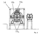
- Figure 1 is a plan view of the embodiment of the present invention.
- Figure 2 is a view taken along the line of arrows II-II in Figure 1.
- Figure 3 is a view taken along the line of arrows III-III in Figure 1.
- Figure 4 is a view taken along the line of arrows IV-IV in Figure 1.
- Figure 5 is a view taken along the line of arrows V-V in Figure 1.
- Figure 5 is a view taken along the line of arrows V-V in Figure 1.
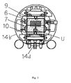
- Figure 6 is an expanded fragmentary view of Figure 5 for explaining the operation of a reversing station, showing an upper level truck and a lower level truck, which are transferred into the station and are sandwiching a cope held in a flask and a drag held in a flask.
- Figure 7 is a cross-sectional side view, similar to Figure 6, for explaining the operation of the reversing station, showing the upper and lower level trucks being rotated clockwise through 180° from the position shown in Figure 6.
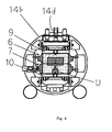
- Figure 8 is a cross-sectional side view, similar to Figure 7, for explaining the operation of the reversing station, showing the upper and lower level trucks being rotated anticlockwise through 180°.
- Figure 9 is a cross-sectional side view of the first embodiment that uses a mold-drawing means.
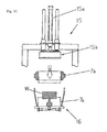
- Figure 10 is a cross-sectional side view of means for separating a tight-flask drag.
- Figure 11 is a cross-sectional side view of the second embodiment that uses a mold-drawing means.
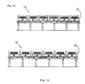
- Figure 12 is a side view of a first embodiment of the secondary cooling line.
- Figure 13 is a side view of a second embodiment of the secondary cooling line.
- The first embodiment of the present invention will be explained based on the drawings. In Figure 1 a level-truck-mounting station A is disposed midway of a first transfer line 1, and a level-truck-separating station B is disposed midway of a second transfer line 2. Further, a mold-transfer device 3, which is provided with a transfer truck 3a, is disposed outside the terminal end of the first transfer line 1 and the starting end of the second transfer line 2. Further, at the outside of the mold-transfer device 3 a
cushioning device 4 is disposed on the first transfer line 1, while a mold-feeding device 5 is disposed on the second transfer line 2. Further, a reversing station C is disposed on the second transfer line 2 between the level-truck-separating station B and the mold-transfer device 3. - The operation of the demolding equipment, which has the above-explained structure, will be explained below. In the second transfer line 2 shown in Figure 2, by extending a cylinder of the mold-feeding device 5 (not shown in Figure 2) when the rod of a
cylinder 4a of theopposing cushioning device 4 is extended, and by retracting thecylinder 4a of thecushioning device 4, a group of successive tight-flask molds 8 (eachmold 8 including a pair of tight-flask mold halves, i.e., a tight-flask cope 7 and a tight-flask drag 6, both are sand mold halves) are transferred ahead (in the direction shown by an while arrow in Figure 2) by one pitch (i.e., by one flask). As shown in Figure 2, the tight-flask cope 7 and the tight-flask drag 6 of the tight-flask mold 8 are mated each other so that the tight-flask cope 7 is placed on the tight-flask drag 6, with their gate U facing upward, and they have been poured with molten metal and are transferred on alower level truck 9. - As the group of the tight-
flask molds 8 is transferred ahead by one pitch, a tight-flask mold 8 placed on thelower level truck 9 is transferred to the level-truck-mounting station A. At the station A, anupper level truck 10 is placed on the tight-flask mold 8 so that it opposes thelower level truck 9. A level-truck-transfer device 11 puts theupper level truck 10 on the tight-flask mold 8. Below the level-truck-transfer device 11 will be explained. - As shown in Figure 4, the level-truck-
transfer device 11 has a level-truck-separating means 12, the means also acting as a level-truck-placing means. Further, the level-truck-transfer device 11 also has a level-truck-transfer means 13. First, the level-truck-separating means 12 is explained. In the level-truck-separating means 12, a pair ofopposing arms nail members cylinder 12c. Thenail members arums cylinder 12c are integrally lifted by a liftingcylinder 12d. The level-truck-separating means 12 acts as said level-truck placing means at the level-truck-mounting station A. - Next, the level-truck-transfer means 13 is explained. The lifting
cylinder 12d of the level-truck-separating means 12 is mounted on atruck 13a, which is reciprocatingly moved between the level-truck-mounting station A and level-truck-separating station B by a truck-moving cylinder 13b. - The operation at the level-truck-mounting station A is now explained in detail. A
lower level truck 9, which has been separated at the level-truck-separating station B, and atruck 13 wait at the level-truck-mounting station A. From this stage, the group of the tight-flask molds 8 are transferred ahead by one pitch, and hence a tight-flask mold 8 placed on thelower level truck 9 is transferred to the level-truck-mounting station A. - By extending the lifting
cylinder 12d, thearms lower level truck 9 is placed on the tight-flask cope 7 of the tight-flask mold 8 as an "upper level truck 10". When thearms cylinder 12c. From this stage, the liftingcylinder 12d is retracted, to integrally lift thenail members arums closing cylinder 12c. The truck-moving cylinder 13b is then extended, to transfer thetruck 13a to the level-truck-separating station B. - As the group of the tight-
flask molds 8 is then transferred ahead by one pitch, as explained above, the tight-flask mold 8, thelower level truck 9, and theupper level truck 10 of the level-truck-mounting station A are integrally transferred therefrom. Further, per the one pitch transfer of the group of the tight-flask molds 8, the tight-flask mold 8, thelower level truck 9, and theupper level truck 10 of the terminal end of the first transfer line 1 are put on the transfer truck 3a, which is waiting at the first transfer line 1 side. The transfer truck 3a, and the tight-flask mold 8, thelower level truck 9, and theupper level truck 10, which are placed on the transfer truck 3a, are moved to the second transfer line 2 side in the conventional manner by operating a motor 3b (see Figure 1). - Further, as in the first transfer line 1, the group of the tight-
flask molds 8 is transferred ahead by one pitch in the second transfer line 2. Namely, in the second transfer line 2 in Figure 3, by extending a cylinder 5a of the mold-feedingdevice 5 when the cylinder rod of the opposing cushioning device (not shown in Figure 3) is extended, and by retracting the cylinder rod of the opposing cushioning device, the group of successive tight-flask mold 8 are transferred ahead (in the direction of white arrow in Figure 3) by one pitch (by one flask). Accordingly, the space above the transfer truck 3a will be vacant. The transfer truck 3a is then moved to the first transfer line 1 side by reversely operating the motor 3b (see Figure 1). - Further, the group of the tight-
flask molds 8 is transferred ahead by one pitch, the tight-flask mold 8, thelower level truck 9, and theupper level truck 10 are transferred to the reversing station C. They are reversed at the reversing station C, with the tight-flask molds 8 being sandwiched between thelower level truck 9 and theupper level truck 10, so that the gate U faces downward. The reversing is carried out by a mold-reversingdevice 14, which will be explained below. - In Figures 3 and 5, circular reversing
bodies rotatable rollers motors flask mold 8, thelower level truck 9, and theupper level truck 10 are transferred in between the reversingbody depressing cylinder 14d, the tight-flask mold 8 is kept sandwiched between thelower level truck 9 and theupper level truck 10. It is released from them when thedepressing cylinder 14d is retracted. - The operation at the reversing station C will be explained below in detail. As the group of the tight-
flask molds 8 is transferred ahead by one pitch, the tight-flask mold 8 with its gate U facing upward, thelower level truck 9, and theupper level truck 10 are transferred in between the reversingbody depressing cylinder 14d, the tight-flask mold 8 is then sandwiched between thelower level truck 9 and theupper level truck 10, as shown in Figure 6. - The
motors flask mold 8, thelower level truck 9, theupper level truck 10, and the reversingbodies upper level truck 10, the tight-flask cope 7, the tight-flask drag 6, and thelower level truck 9, are superimposed on one another, with the gate U facing downward. Thedepressing cylinder 14d is then retracted to disengage the tight-flask mold 8 from the lower andupper level trucks - As the group of the tight-
flask molds 8 is then transferred ahead by one pitch, the right-turned, tight-flask mold 8,lower level truck 9, andupper level truck 10, are transferred from the reversingbodies lower level truck 9, a tight-flask mold 8, and anupper level truck 10 is transferred in between the reversingbody flask mold 8 is then sandwiched between thelower level truck 9 and theupper level truck 10 by extending thedepressing cylinder 14d. - The
motors lower level truck 9, the tight-flask mold 8, theupper level truck 10, and the reversingbodies upper level truck 10, the tight-flask cope 7, the tight-flask drag 6, and thelower level truck 9, are superimposed on one another, with the gate U facing downward. Thedepressing cylinder 14d is then retracted to disengage the tight-flask mold 8 from the lower andupper level trucks flask molds 8 is then transferred ahead by one pitch. The above operation process will be repeated. - The tight-
flask mold 8, thelower level truck 9, and theupper level truck 10, which have been reversed as explained above and have been transferred from the reversing station C, are transferred to the level-truck-separating station B as the group of the tight-flask molds 8 are transferred ahead by one pitch. At the level-truck-separating station B thelower level truck 9, which is now located on the tight-flask drag 6, is separated. - The operation at the level-truck-separating station B will be explained below in detail. As the group of the tight-
flask molds 8 are transferred ahead by one pitch, theupper level truck 10, the tight-flask cope 7, the tight-flask drag 6, and thelower level truck 9, which are superimposed on one another from below to above, are transferred to the level-truck-separating station B. Thelifting cylinder 12d mounted on thetruck 13a, which truck has been moved from the level-truck-mounting station A to the level-truck-separating station B, is extended to allow thearms - When the
arms closing cylinder 12c. From this stage, thelifting cylinder 12d is retracted to catch and move thelower level truck 9 upward with thenails members lower level truck 9 is returned to the level-truck-mounting station A, together with thetruck 13, by retracting the truck-moving cylinder 13b. Thelower level truck 9 is placed as an "upper level truck 10" on a tight-flask cope 7 of a tight-flask mold 8 that is transferred to the level-truck-mounting station A. The tight-flask mold 8 and theupper level truck 10, which have been separated from thelower level truck 9, are transferred from the level-truck-separating station B as the group of the tight-flask molds 8 is transferred ahead by one pitch. Theupper level truck 10 is then separated from the tight-flask mold 8 by an upper-level-truck-separating means (not shown) in a post-process in the second transfer line 2. Thus, the tight-flask mold 8 remains there, with its gate U facing downward. The separation of theupper level truck 10 from the tight-flask mold 8 may be performed by moving the tight-flask mold 8 upward using the same means as a tight-flask-drag separating means 17, which will be explained below, or by moving theupper level truck 10 downward, while the tight-flask mold 8 is supported by rollers or any other means. As shown in Figure 9, the tight-flask mold 8 separated from theupper level truck 10 is transferred to a position just below a mold-drawing means 15 by a conventional device (not shown). In the mold-drawing means 15, by downwardly extending adrawing cylinder 15a, a cope 7a, a drag 6a, and an as-cast product W are downwardly drawn out of thetight flasks drawing head 15b. A series of secondary cooling pallet-like trucks 16, each acting as a pallet for receiving and for secondary cooling the falling cope and drag, are transferred to the position below the mold-drawing means 15. The cope 7a, the drag 6a, and the as-cast product W are put in the secondary cooling pallet-like truck 16. - The series of secondary cooling pallet-
like trucks 16, each carrying the cope 7a, the drag 6a, and the as-cast product W, are transferred ahead pitch by pitch in asecond cooling line 18 in Figure 12. - The
empty flasks drawing head 15b reaches its upper stop end by retracting thedrawing cylinder 15a. - Next, the second embodiment of the present invention will be explained. Some initial processes of the second embodiment are the same as those in the first embodiment, up to the process wherein the
upper level truck 10 is separated from the tight-flask mold 8 by the upper-level-truck separating means (not shown) in the post-process in the second transfer line 2, and thus the tight-flask mold 8 remains, with the gate U facing upward. - The remaining tight-
flask mold 8 is then transferred by a transfer means (not shown) to a position just below a tight-flask-drag separating means 17 (Figure 10). At the tight-flask-drag separating means 17, first, alifting cylinder 17a is extended to its lower stop end, and an opening/closing cylinder 17b is then retracted to closearms lifting cylinder 17a is retracted to catch and move the tight-flask drag 6 upward bynail members lifting cylinder 17a, as shown in Figure 10. Accordingly, the tight-flask drag 6 is separated from the tight-flask cope 7 in which the as-cast product W remains, with the gate U facing downward. In this separation the tight-tlask drag 6 may be separated upwardly as shown in Figure 10. Alternatively, the tight-flask cope 7 holding the as-cast product W may be placed on a liftable table (not shown), and the table is then lowered, while the tight-flask drag 6 is supported, to separate the tight-flask cope 7 and the as-cast product W downward from the tight-flask drag 6. - The separated tight-
flask drag 6 is then transferred for the following process (not shown), and the drag 6a is drawn during the process. Further, the tight-flask cope 7 and the as-cast product W are transferred by a known transfer means (not shown) to the position just below the mold-drawing means 15, as shown in Figure 11. This mold-drawing means 15 is the same as the mold-drawing means 15 in the first embodiment. By extending the mold-drawing cylinder 15a, the as-cast product W and the cope 7a are drawn downward from theflask 7b by the drawinghead 15b. The same as in the first embodiment, the secondary cooling pallet-like trucks 16 as mold receiving means are sequentially transferred to the position below the as-cast product W and the cope 7a to be drawn. The drawn as-cast product W and cope 7a are put in the secondary cooling pallet-like truck 16. - Further, as shown in Figure 13, the group of the secondary cooling pallet-
like trucks 16, each carrying the as-cast product W and the cope 7a, is transferred in thesecondary cooling line 18 pitch by pitch. After the as-cast product W and the cope 7a are drawn, the empty cope 7b is transferred for the following process (not shown) after thedrawing head 15b reaches its upper stop end by retracting thedrawing cylinder 15a. - In the present invention, as explained above, a tight-flask cope 7 is placed on a tight-
flask drag 6 for mating, with their gate U facing upward, and the tight-flask mold 8 (an assembly of the tight-flask cope 7 and the tight-flask drag 6), which has been poured with molten metal, is then reversed, so that the gate U faces downward. The assembly of the cope 7a, the drag 6a, and the as-cast product W, is then drawn from the reversed tight-flask mold 8, which holds the downwardly-facing gate U, from above to below. Alternatively, the tight-flask drag 6, which is positioned above after reversing, is separated from the tight-flask cope 7 in which the as-cast product W and the downwardly-facing gate U remain. The as-cast product W and the downwardly-facing gate U are then drawn from theflask 7b, from above to below. Accordingly, since the assembly of the as-cast product W and the downwardly-facing gate U, which is located below the product W, drops, the product W is not subjected to dents, thereby greatly reducing dents produced in the product. - Although the tight-
flask molds 8 may be transferred on a roller conveyor, they are normally transferred on level trucks. When the tight-flask mold 8 is transferred on the level truck, generally it is difficult to reverse the mold carried on the level truck and transfer it thereafter. However, in the present invention anupper level truck 10 is placed on the tight-flask mold 8 that has been poured with molten metal. This allows the mold to be easily transferred after it is reversed. Further, thelower level truck 9, which has been reversed and thus located on the tight-flask 6, is separated at the level-truck-separating station B and is then returned to the level-truck-mountíng station A and used there as an upper-level-truck 10 to be placed on a tight-flask cope 7 of a tight-flask mold 8 that is transferred in the level-truck-mounting station A. Since the level trucks are circulated, changing from the upper-level-trucks 10 to the lower-level trucks 9 and vice versa, the number of the upper-level-trucks 10 to be used can be reduced, though they are necessary to be placed on the tight-flask molds 8. - Further, in the second embodiment the tight-
flask drag 6, which has been reversed and thus located above, is separated from the reversed tight-flask mold 8 with the gate U facing downward, leaving the as-cast product W in the tight-flask cope 7, which has been reversed and thus located below. The as-cast product W and the cope 7a are then drawn from the tight-flask cope 7, from above to below. This method produces advantages. The molding sand of the drag 6a drawn from the separated tight-flask drag 6 does not need to be transferred in the secondary cooling pallet-like truck 16, but it can be quickly returned to a sand processing line (not shown) for use for producing new molds. Thus the quantity of the sand to be used for the entire sand line can be reduced. Further, since as shown in Figure 13 the as-cast product is transferred with a large part of it's surface exposed to the atmosphere, it can be more effectively cooled, reducing the time to secondarily cool it and shortening thesecondary cooling line 18.
Claims (8)
- A demolding method, comprising the steps of placing a tight-flask cope on a tight-flask drag for mating, such that a gate for the tight-flask cope and drag faces upward, and of reversing the tight-flask cope and drag after the tight-flask cope and drag are poured with molten metal such that the gate faces downward; and drawing a cope, a drag, and an as-cast product from the reversed tight-flask cope and drag, with the gate facing downward, from above to below.
- A demolding method, comprising the steps of placing a tight-flask cope on a tight-flask drag for mating, such that a gate for the tight-flask cope and drag faces upward, and of reversing the tight-flask cope and drag after the tight-flask cope and drag are poured with molten metal such that the gate faces downward; separating only the tight-flask drag, which has been reversed and thus located above, from the tight-flask cope, which has been reversed and thus located below the tight-flask drag, allowing an as-cast product and the downwardly facing gate to remain in the tight-flask cope; and drawing a cope, a drag, and the as-cast product from the reversed tight-flask cope and drag, from above to below.
- A demolding method, comprising the steps of placing a tight-flask cope on a tight-flask drag for mating, such that a gate for the tight-flask cope and drag faces upward, and after the mated tight-flask cope and drag are poured with molten metal, transferring the mated tight-flask cope and drag placed on a lower level truck to a level-truck-mounting station; placing an upper level truck on the tight-flask cope and drag at the level-truck-mounting station such that the upper level truck faces the lower level truck; transferring the tight-flask cope and drag and the lower and upper level trucks from the level-truck-mounting station to a reversing station; reversing the tight-flask cope and drag and the upper and lower level trucks at the reversing station with the tight-flask cope and drag being sandwiched between the upper level truck and the lower level truck so that the upwardly facing gate faces downward; transferring the reversed tight-flask cope and drag and upper and lower level trucks from the reversing station to a level-truck-separating station; separating at the level-truck-separating station the lower level truck, which has been reversed and thus located above; returning the separated lower level truck to the level-truck-mounting station, and placing the returned lower level truck as an upper level truck on a tight-flask cope that is transferred together with a mated tight-flask drag to the level-truck-mounting station; separating the upper level truck from an assembly of the tight-flask cope and drag and the upper level truck, which assembly has been transferred from the level-truck-separating station; and drawing a cope, a drag, and an as-cast product, with the gate facing downward, from the tight-flask cope and drag, from above to below.
- A demolding method, comprising the steps of placing a tight-flask cope on a tight-flask drag for mating, such that a gate for the tight-flask cope and drag faces upward, and after the mated tight-flask cope and drag are poured with molten metal, transferring the mated tight-flask cope and drag placed on a lower level truck to a level-truck-mounting station; placing an upper level truck on the tight-flask cope and drag at the level-truck-mounting station such that the upper level truck faces the lower level truck; transferring the tight-flask cope and drag and the lower and upper level trucks from the level-truck-mounting station to a reversing station; reversing the tight-flask cope and drag and the upper and lower level trucks at the reversing station with the tight-flask cope and drag being sandwiched between the upper level truck and the lower level truck so that the upwardly facing gate faces downward; transferring the reversed tight-flask cope and drag and upper and lower level trucks from the reversing station to a level-truck-separating station; separating at the level-truck-separating station the lower level truck, which has been reversed and thus located above; returning the separated lower level truck to the level-truck-mounting station, and placing the returned lower level truck as an upper level truck on a tight-flask cope that is transferred together with a mated tight-flask drag to the level-truck-mounting station; separating the upper level truck from an assembly of the tight-flask cope and drag and the upper level truck, which assembly has been transferred from the level-truck-separating station; separating the tight-flask drag, which is located above, from the tight-flask cope, which has been reversed and thus located under the tight-flask drag, allowing an as-cast product to remain in the tight-flask cope; and drawing a cope and the as-cast product from the tight-flask cope holding the as-cast product, from above to below.
- A demolding equipment, comprising a reversing means for reversing a tight-flask cope placed on a tight-flask drag for mating such that a gate for the tight-flask cope and drag faces upward, the mated tight-flask cope and drag being poured with molten metal, such that the gate faces downward; and a mold-drawing means for drawing a cope, a drag, and an as-cast product from the reversed tight-flask cope and drag, with the gate facing downward, from above to below.
- A demolding equipment, comprising a reversing means for reversing a tight-flask cope placed on a tight-flask drag for mating such that a gate for the tight-flask cope and drag faces upward, the mated tight-flask cope and drag being poured with molten metal, such that the gate faces downward; a tight-flask drag-separating means for separating only the tight-flask drag, which has been reversed and thus located above, from the tight-flask cope, which has been reversed and thus located below the tight-flask drag, allowing an as-cast product and the downwardly facing gate to remain in the tight-flask cope; and drawing a cope, a drag, and the as-cast product from the reversed tight-flask cope and drag, from above to below.
- A demolding equipment, comprising a level-truck-mounting means for placing an upper level truck on a opposing lower level truck on which mated tight-flask cope and drag are carried, with a gate for the tight-flask cope and drag facing upward, the mated tight-flask cope and drag being poured with molten metal and being transferred to a level-truck-mounting station; a reversing means for reversing at a reversing station disposed downstream the level-truck-mounting station the tight-flask cope and drag and the upper and lower level trucks, with the tight-flask cope and drag being sandwiched between the upper level truck and the lower level truck, such that the gate faces downward; a level-truck-separating means for separating at a level-truck-separating station disposed downstream the reversing station the lower level truck, which has been reversed and thus located on the tight-flask drag; a level-truck-transfer means for returning the separated lower level truck to the level-truck-mounting station; an upper-level-truck-separating means for separating the upper level truck from the tight-flask cope and the upper level truck, which has been transferred from the level-truck-separating station; and a mold-drawing means for drawing a cope, a drag, and an as-cast product from the tight-flask cope and drag, with the gate facing downward, from above to below.
- A demolding equipment, comprising a level-truck-mounting means for placing an upper level truck on a opposing lower level truck on which mated tight-flask cope and drag are carried, with a gate for the tight-flask cope and drag facing upward, the mated tight-flask cope and drag being poured with molten metal and being transferred to a level-truck-mounting station; a reversing means for reversing at a reversing station disposed downstream the level-truck-mounting station the tight-flask cope and drag and the upper and lower level trucks, with the tight-flask cope and drag being sandwiched between the upper level truck and the lower level truck, such that the gate faces downward; a level-truck-separating means for separating at a level-truck-separating station disposed downstream the reversing station the lower level truck, which has been reversed and thus located on the tight-flask drag; a level-truck-transfer means for returning the separated lower level truck to the level-truck-mounting station; an upper-level-truck-separating means for separating the upper level truck from the tight-flask cope and the upper level truck, which has been transferred from the level-truck-separating station; a tight-flask-drag separating means for separating only the tight-flask drag, which is located above, from the tight-flask cope located under the tight-flask drag, allowing an as-cast product to remain in the tight-flask cope; and a mold-drawing means for drawing a cope and the as-cast product from the tight-flask cope, from above to below.
Applications Claiming Priority (2)
| Application Number | Priority Date | Filing Date | Title |
|---|---|---|---|
| JP2004373652A JP4337100B2 (en) | 2004-12-24 | 2004-12-24 | Mold separation method and equipment |
| PCT/JP2005/023057 WO2006068029A1 (en) | 2004-12-24 | 2005-12-15 | Mold disassembly method and installation therefor |
Publications (3)
| Publication Number | Publication Date |
|---|---|
| EP1844882A1 true EP1844882A1 (en) | 2007-10-17 |
| EP1844882A4 EP1844882A4 (en) | 2009-02-25 |
| EP1844882B1 EP1844882B1 (en) | 2017-06-14 |
Family
ID=36601629
Family Applications (1)
| Application Number | Title | Priority Date | Filing Date |
|---|---|---|---|
| EP05816685.1A Expired - Lifetime EP1844882B1 (en) | 2004-12-24 | 2005-12-15 | Mold disassembly method and installation therefor |
Country Status (7)
| Country | Link |
|---|---|
| US (1) | US7905270B2 (en) |
| EP (1) | EP1844882B1 (en) |
| JP (1) | JP4337100B2 (en) |
| KR (1) | KR100919083B1 (en) |
| CN (1) | CN100515610C (en) |
| BR (1) | BRPI0516409B1 (en) |
| WO (1) | WO2006068029A1 (en) |
Families Citing this family (8)
| Publication number | Priority date | Publication date | Assignee | Title |
|---|---|---|---|---|
| JP5403403B2 (en) * | 2009-03-18 | 2014-01-29 | 新東工業株式会社 | Casting line and sand removal method |
| JP5724700B2 (en) * | 2011-07-12 | 2015-05-27 | 新東工業株式会社 | Jacket loosening method and jacket loosening device in frameless mold pouring cooling line |
| CN103614764B (en) * | 2013-10-18 | 2016-03-09 | 中国电子科技集团公司第十研究所 | Electroplating thickness high consistence ceramic membrane conductor gold plating hanging tool |
| CN104439208B (en) * | 2014-12-16 | 2017-02-22 | 中机中联工程有限公司 | Piston ring casting and shakeout automation line |
| CN104889373B (en) * | 2015-06-15 | 2017-03-08 | 杭州沪宁电梯部件股份有限公司 | The branch mailbox overmolded liftout attachment of sand casting system |
| CN110722136B (en) * | 2019-10-18 | 2021-03-23 | 重庆福锦塑胶有限责任公司 | Automatic sand feeding system for sand mold casting |
| CN111531152B (en) * | 2020-04-30 | 2021-09-24 | 邵东智能制造技术研究院有限公司 | Blanking device suitable for mold taking and closing of multi-size mold |
| CN116197366B (en) * | 2023-03-08 | 2026-05-08 | 河北聚盛宏鑫模具科技有限公司 | A copper alloy glass mold casting coated sand annular gating line |
Family Cites Families (10)
| Publication number | Priority date | Publication date | Assignee | Title |
|---|---|---|---|---|
| US2651087A (en) * | 1947-05-08 | 1953-09-08 | Harrison E Fellows | Mold making machine |
| JPS591062A (en) * | 1982-06-28 | 1984-01-06 | Sintokogio Ltd | Knock-out line for casting mold |
| JPS591460A (en) | 1982-06-29 | 1984-01-06 | Mitsui Toatsu Chem Inc | Production of 2-mercaptoethylamine hydrohalide salt |
| JPH0265471A (en) | 1988-08-31 | 1990-03-06 | Matsushita Electric Ind Co Ltd | contour correction device |
| JPH0522367Y2 (en) * | 1988-10-31 | 1993-06-08 | ||
| JPH115153A (en) * | 1997-06-13 | 1999-01-12 | Sintokogio Ltd | Mold release method |
| JP3304071B2 (en) | 1998-12-21 | 2002-07-22 | 新東工業株式会社 | Mold release method and equipment |
| JP2001025859A (en) * | 1999-07-14 | 2001-01-30 | Sintokogio Ltd | Method and apparatus for separating casting mold and casting material |
| JP2001071123A (en) * | 1999-09-08 | 2001-03-21 | Sintokogio Ltd | Casting material removal system from green sand mold with frame |
| EP1228826A4 (en) * | 1999-07-14 | 2004-04-14 | Sintokogio Ltd | Method and device for separating casting material from poured green sand mold |
-
2004
- 2004-12-24 JP JP2004373652A patent/JP4337100B2/en not_active Expired - Fee Related
-
2005
- 2005-12-15 EP EP05816685.1A patent/EP1844882B1/en not_active Expired - Lifetime
- 2005-12-15 WO PCT/JP2005/023057 patent/WO2006068029A1/en not_active Ceased
- 2005-12-15 US US11/793,801 patent/US7905270B2/en not_active Expired - Fee Related
- 2005-12-15 BR BRPI0516409-5A patent/BRPI0516409B1/en not_active IP Right Cessation
- 2005-12-15 CN CNB2005800482357A patent/CN100515610C/en not_active Expired - Lifetime
- 2005-12-15 KR KR1020077016984A patent/KR100919083B1/en not_active Expired - Fee Related
Also Published As
| Publication number | Publication date |
|---|---|
| JP2006175507A (en) | 2006-07-06 |
| JP4337100B2 (en) | 2009-09-30 |
| EP1844882A4 (en) | 2009-02-25 |
| BRPI0516409B1 (en) | 2017-09-26 |
| US20090114361A1 (en) | 2009-05-07 |
| BRPI0516409A (en) | 2008-09-02 |
| EP1844882B1 (en) | 2017-06-14 |
| US7905270B2 (en) | 2011-03-15 |
| WO2006068029A1 (en) | 2006-06-29 |
| CN100515610C (en) | 2009-07-22 |
| CN101119816A (en) | 2008-02-06 |
| KR100919083B1 (en) | 2009-09-28 |
| KR20070095972A (en) | 2007-10-01 |
Similar Documents
| Publication | Publication Date | Title |
|---|---|---|
| CN101652207B (en) | Operation method of upper die for lower die in permanent mold casting device and permanent mold casting device for use in that operation method | |
| CN110814284B (en) | Piston ring casting process | |
| CN105478684B (en) | Full-automatic core shooter | |
| US7905270B2 (en) | Demolding method and equipment | |
| CN110202125B (en) | Casting production line | |
| CN102009156B (en) | Production equipment of industrial robot by using low-pressure casting and use method thereof | |
| KR100929159B1 (en) | Mold circulating multi casting method and apparatus | |
| CN115283660A (en) | Mould static pressure molding line | |
| CN116100014A (en) | Iron mold sand coating production line | |
| JP2010172955A (en) | Line facility for molding and casting | |
| JP4437765B2 (en) | Demolding device for sand mold with poured frame | |
| CN112264567B (en) | Die forging method for traveling block lifting ring for petroleum drilling machine lifting system | |
| CN115415486A (en) | Circulating static pressure line capable of automatically replacing box | |
| JP4370549B2 (en) | Molding line and casting line | |
| CN208583965U (en) | A kind of cinder ladle cast gate of long casting automatically removes device | |
| CN201950200U (en) | Production equipment for low-pressure casting of industrial robots | |
| JP2007069238A (en) | Mold casting equipment | |
| CN110814302B (en) | Six-station sand mold forming machine | |
| JP2007301608A (en) | Mold transfer equipment and mold making equipment using the mold transfer equipment | |
| JP2014018853A (en) | Method and device for transporting cast frames | |
| CN210548079U (en) | Casting production line | |
| JP4529131B2 (en) | Pouring mold cooling line | |
| CN221161233U (en) | Automatic demolding reverse mold platform | |
| JPS6348623B2 (en) | ||
| CN113102745B (en) | Three-dimensional roller bed production line based on sand box technology |
Legal Events
| Date | Code | Title | Description |
|---|---|---|---|
| PUAI | Public reference made under article 153(3) epc to a published international application that has entered the european phase |
Free format text: ORIGINAL CODE: 0009012 |
|
| 17P | Request for examination filed |
Effective date: 20070622 |
|
| AK | Designated contracting states |
Kind code of ref document: A1 Designated state(s): AT BE BG CH CY CZ DE DK EE ES FI FR GB GR HU IE IS IT LI LT LU LV MC NL PL PT RO SE SI SK TR |
|
| DAX | Request for extension of the european patent (deleted) | ||
| A4 | Supplementary search report drawn up and despatched |
Effective date: 20090123 |
|
| 17Q | First examination report despatched |
Effective date: 20090518 |
|
| GRAP | Despatch of communication of intention to grant a patent |
Free format text: ORIGINAL CODE: EPIDOSNIGR1 |
|
| STAA | Information on the status of an ep patent application or granted ep patent |
Free format text: STATUS: GRANT OF PATENT IS INTENDED |
|
| INTG | Intention to grant announced |
Effective date: 20161103 |
|
| GRAS | Grant fee paid |
Free format text: ORIGINAL CODE: EPIDOSNIGR3 |
|
| GRAJ | Information related to disapproval of communication of intention to grant by the applicant or resumption of examination proceedings by the epo deleted |
Free format text: ORIGINAL CODE: EPIDOSDIGR1 |
|
| GRAL | Information related to payment of fee for publishing/printing deleted |
Free format text: ORIGINAL CODE: EPIDOSDIGR3 |
|
| STAA | Information on the status of an ep patent application or granted ep patent |
Free format text: STATUS: EXAMINATION IS IN PROGRESS |
|
| GRAR | Information related to intention to grant a patent recorded |
Free format text: ORIGINAL CODE: EPIDOSNIGR71 |
|
| STAA | Information on the status of an ep patent application or granted ep patent |
Free format text: STATUS: GRANT OF PATENT IS INTENDED |
|
| GRAA | (expected) grant |
Free format text: ORIGINAL CODE: 0009210 |
|
| STAA | Information on the status of an ep patent application or granted ep patent |
Free format text: STATUS: THE PATENT HAS BEEN GRANTED |
|
| INTC | Intention to grant announced (deleted) | ||
| RAP1 | Party data changed (applicant data changed or rights of an application transferred) |
Owner name: SINTOKOGIO, LTD. |
|
| INTG | Intention to grant announced |
Effective date: 20170504 |
|
| AK | Designated contracting states |
Kind code of ref document: B1 Designated state(s): AT BE BG CH CY CZ DE DK EE ES FI FR GB GR HU IE IS IT LI LT LU LV MC NL PL PT RO SE SI SK TR |
|
| REG | Reference to a national code |
Ref country code: GB Ref legal event code: FG4D |
|
| REG | Reference to a national code |
Ref country code: CH Ref legal event code: EP Ref country code: AT Ref legal event code: REF Ref document number: 900482 Country of ref document: AT Kind code of ref document: T Effective date: 20170615 |
|
| REG | Reference to a national code |
Ref country code: IE Ref legal event code: FG4D |
|
| REG | Reference to a national code |
Ref country code: DE Ref legal event code: R096 Ref document number: 602005052138 Country of ref document: DE |
|
| REG | Reference to a national code |
Ref country code: NL Ref legal event code: MP Effective date: 20170614 |
|
| REG | Reference to a national code |
Ref country code: LT Ref legal event code: MG4D |
|
| PG25 | Lapsed in a contracting state [announced via postgrant information from national office to epo] |
Ref country code: ES Free format text: LAPSE BECAUSE OF FAILURE TO SUBMIT A TRANSLATION OF THE DESCRIPTION OR TO PAY THE FEE WITHIN THE PRESCRIBED TIME-LIMIT Effective date: 20170614 Ref country code: GR Free format text: LAPSE BECAUSE OF FAILURE TO SUBMIT A TRANSLATION OF THE DESCRIPTION OR TO PAY THE FEE WITHIN THE PRESCRIBED TIME-LIMIT Effective date: 20170915 Ref country code: FI Free format text: LAPSE BECAUSE OF FAILURE TO SUBMIT A TRANSLATION OF THE DESCRIPTION OR TO PAY THE FEE WITHIN THE PRESCRIBED TIME-LIMIT Effective date: 20170614 Ref country code: LT Free format text: LAPSE BECAUSE OF FAILURE TO SUBMIT A TRANSLATION OF THE DESCRIPTION OR TO PAY THE FEE WITHIN THE PRESCRIBED TIME-LIMIT Effective date: 20170614 |
|
| REG | Reference to a national code |
Ref country code: AT Ref legal event code: MK05 Ref document number: 900482 Country of ref document: AT Kind code of ref document: T Effective date: 20170614 |
|
| PG25 | Lapsed in a contracting state [announced via postgrant information from national office to epo] |
Ref country code: NL Free format text: LAPSE BECAUSE OF FAILURE TO SUBMIT A TRANSLATION OF THE DESCRIPTION OR TO PAY THE FEE WITHIN THE PRESCRIBED TIME-LIMIT Effective date: 20170614 Ref country code: LV Free format text: LAPSE BECAUSE OF FAILURE TO SUBMIT A TRANSLATION OF THE DESCRIPTION OR TO PAY THE FEE WITHIN THE PRESCRIBED TIME-LIMIT Effective date: 20170614 Ref country code: BG Free format text: LAPSE BECAUSE OF FAILURE TO SUBMIT A TRANSLATION OF THE DESCRIPTION OR TO PAY THE FEE WITHIN THE PRESCRIBED TIME-LIMIT Effective date: 20170914 Ref country code: SE Free format text: LAPSE BECAUSE OF FAILURE TO SUBMIT A TRANSLATION OF THE DESCRIPTION OR TO PAY THE FEE WITHIN THE PRESCRIBED TIME-LIMIT Effective date: 20170614 |
|
| PG25 | Lapsed in a contracting state [announced via postgrant information from national office to epo] |
Ref country code: CZ Free format text: LAPSE BECAUSE OF FAILURE TO SUBMIT A TRANSLATION OF THE DESCRIPTION OR TO PAY THE FEE WITHIN THE PRESCRIBED TIME-LIMIT Effective date: 20170614 Ref country code: AT Free format text: LAPSE BECAUSE OF FAILURE TO SUBMIT A TRANSLATION OF THE DESCRIPTION OR TO PAY THE FEE WITHIN THE PRESCRIBED TIME-LIMIT Effective date: 20170614 Ref country code: RO Free format text: LAPSE BECAUSE OF FAILURE TO SUBMIT A TRANSLATION OF THE DESCRIPTION OR TO PAY THE FEE WITHIN THE PRESCRIBED TIME-LIMIT Effective date: 20170614 Ref country code: EE Free format text: LAPSE BECAUSE OF FAILURE TO SUBMIT A TRANSLATION OF THE DESCRIPTION OR TO PAY THE FEE WITHIN THE PRESCRIBED TIME-LIMIT Effective date: 20170614 Ref country code: SK Free format text: LAPSE BECAUSE OF FAILURE TO SUBMIT A TRANSLATION OF THE DESCRIPTION OR TO PAY THE FEE WITHIN THE PRESCRIBED TIME-LIMIT Effective date: 20170614 |
|
| PGFP | Annual fee paid to national office [announced via postgrant information from national office to epo] |
Ref country code: TR Payment date: 20171213 Year of fee payment: 13 |
|
| PG25 | Lapsed in a contracting state [announced via postgrant information from national office to epo] |
Ref country code: PL Free format text: LAPSE BECAUSE OF FAILURE TO SUBMIT A TRANSLATION OF THE DESCRIPTION OR TO PAY THE FEE WITHIN THE PRESCRIBED TIME-LIMIT Effective date: 20170614 Ref country code: IT Free format text: LAPSE BECAUSE OF FAILURE TO SUBMIT A TRANSLATION OF THE DESCRIPTION OR TO PAY THE FEE WITHIN THE PRESCRIBED TIME-LIMIT Effective date: 20170614 Ref country code: IS Free format text: LAPSE BECAUSE OF FAILURE TO SUBMIT A TRANSLATION OF THE DESCRIPTION OR TO PAY THE FEE WITHIN THE PRESCRIBED TIME-LIMIT Effective date: 20171014 |
|
| REG | Reference to a national code |
Ref country code: DE Ref legal event code: R097 Ref document number: 602005052138 Country of ref document: DE |
|
| PLBE | No opposition filed within time limit |
Free format text: ORIGINAL CODE: 0009261 |
|
| STAA | Information on the status of an ep patent application or granted ep patent |
Free format text: STATUS: NO OPPOSITION FILED WITHIN TIME LIMIT |
|
| PG25 | Lapsed in a contracting state [announced via postgrant information from national office to epo] |
Ref country code: DK Free format text: LAPSE BECAUSE OF FAILURE TO SUBMIT A TRANSLATION OF THE DESCRIPTION OR TO PAY THE FEE WITHIN THE PRESCRIBED TIME-LIMIT Effective date: 20170614 |
|
| 26N | No opposition filed |
Effective date: 20180315 |
|
| REG | Reference to a national code |
Ref country code: CH Ref legal event code: PL |
|
| GBPC | Gb: european patent ceased through non-payment of renewal fee |
Effective date: 20171215 |
|
| PG25 | Lapsed in a contracting state [announced via postgrant information from national office to epo] |
Ref country code: SI Free format text: LAPSE BECAUSE OF FAILURE TO SUBMIT A TRANSLATION OF THE DESCRIPTION OR TO PAY THE FEE WITHIN THE PRESCRIBED TIME-LIMIT Effective date: 20170614 |
|
| REG | Reference to a national code |
Ref country code: IE Ref legal event code: MM4A |
|
| PG25 | Lapsed in a contracting state [announced via postgrant information from national office to epo] |
Ref country code: LU Free format text: LAPSE BECAUSE OF NON-PAYMENT OF DUE FEES Effective date: 20171215 |
|
| REG | Reference to a national code |
Ref country code: FR Ref legal event code: ST Effective date: 20180831 |
|
| REG | Reference to a national code |
Ref country code: BE Ref legal event code: MM Effective date: 20171231 |
|
| PG25 | Lapsed in a contracting state [announced via postgrant information from national office to epo] |
Ref country code: FR Free format text: LAPSE BECAUSE OF NON-PAYMENT OF DUE FEES Effective date: 20180102 Ref country code: IE Free format text: LAPSE BECAUSE OF NON-PAYMENT OF DUE FEES Effective date: 20171215 |
|
| PG25 | Lapsed in a contracting state [announced via postgrant information from national office to epo] |
Ref country code: GB Free format text: LAPSE BECAUSE OF NON-PAYMENT OF DUE FEES Effective date: 20171215 Ref country code: CH Free format text: LAPSE BECAUSE OF NON-PAYMENT OF DUE FEES Effective date: 20171231 Ref country code: BE Free format text: LAPSE BECAUSE OF NON-PAYMENT OF DUE FEES Effective date: 20171231 Ref country code: LI Free format text: LAPSE BECAUSE OF NON-PAYMENT OF DUE FEES Effective date: 20171231 |
|
| PG25 | Lapsed in a contracting state [announced via postgrant information from national office to epo] |
Ref country code: MC Free format text: LAPSE BECAUSE OF FAILURE TO SUBMIT A TRANSLATION OF THE DESCRIPTION OR TO PAY THE FEE WITHIN THE PRESCRIBED TIME-LIMIT Effective date: 20170614 Ref country code: HU Free format text: LAPSE BECAUSE OF FAILURE TO SUBMIT A TRANSLATION OF THE DESCRIPTION OR TO PAY THE FEE WITHIN THE PRESCRIBED TIME-LIMIT; INVALID AB INITIO Effective date: 20051215 |
|
| PG25 | Lapsed in a contracting state [announced via postgrant information from national office to epo] |
Ref country code: CY Free format text: LAPSE BECAUSE OF NON-PAYMENT OF DUE FEES Effective date: 20170614 |
|
| PG25 | Lapsed in a contracting state [announced via postgrant information from national office to epo] |
Ref country code: PT Free format text: LAPSE BECAUSE OF FAILURE TO SUBMIT A TRANSLATION OF THE DESCRIPTION OR TO PAY THE FEE WITHIN THE PRESCRIBED TIME-LIMIT Effective date: 20170614 |
|
| PG25 | Lapsed in a contracting state [announced via postgrant information from national office to epo] |
Ref country code: TR Free format text: LAPSE BECAUSE OF NON-PAYMENT OF DUE FEES Effective date: 20201215 |
|
| PGFP | Annual fee paid to national office [announced via postgrant information from national office to epo] |
Ref country code: DE Payment date: 20241210 Year of fee payment: 20 |
|
| REG | Reference to a national code |
Ref country code: DE Ref legal event code: R071 Ref document number: 602005052138 Country of ref document: DE |