EP1844686B1 - Pressure-cooking device with controlled decompression - Google Patents
Pressure-cooking device with controlled decompression Download PDFInfo
- Publication number
- EP1844686B1 EP1844686B1 EP07356045A EP07356045A EP1844686B1 EP 1844686 B1 EP1844686 B1 EP 1844686B1 EP 07356045 A EP07356045 A EP 07356045A EP 07356045 A EP07356045 A EP 07356045A EP 1844686 B1 EP1844686 B1 EP 1844686B1
- Authority
- EP
- European Patent Office
- Prior art keywords
- section
- pressure
- flow section
- appliance
- value
- Prior art date
- Legal status (The legal status is an assumption and is not a legal conclusion. Google has not performed a legal analysis and makes no representation as to the accuracy of the status listed.)
- Active
Links
Images

Classifications
-
- A—HUMAN NECESSITIES
- A47—FURNITURE; DOMESTIC ARTICLES OR APPLIANCES; COFFEE MILLS; SPICE MILLS; SUCTION CLEANERS IN GENERAL
- A47J—KITCHEN EQUIPMENT; COFFEE MILLS; SPICE MILLS; APPARATUS FOR MAKING BEVERAGES
- A47J27/00—Cooking-vessels
- A47J27/08—Pressure-cookers; Lids or locking devices specially adapted therefor
- A47J27/09—Safety devices
- A47J27/092—Devices for automatically releasing pressure before opening
-
- A—HUMAN NECESSITIES
- A47—FURNITURE; DOMESTIC ARTICLES OR APPLIANCES; COFFEE MILLS; SPICE MILLS; SUCTION CLEANERS IN GENERAL
- A47J—KITCHEN EQUIPMENT; COFFEE MILLS; SPICE MILLS; APPARATUS FOR MAKING BEVERAGES
- A47J27/00—Cooking-vessels
- A47J27/08—Pressure-cookers; Lids or locking devices specially adapted therefor
- A47J27/0804—Locking devices
- A47J27/0813—Locking devices using a clamping ring or clamping segments
Definitions
- the present invention relates to the general technical field of food cooking appliances, in particular of domestic nature, intended to form a sealed cooking chamber, in which are cooked foods under steam pressure.
- the present invention more particularly relates to a food cooking apparatus under pressure arranged to form a cooking chamber, provided with a conduit for the establishment of a vapor leakage flow from the inside of the enclosure to the chamber. and defining a first vapor passage section, said apparatus comprising a pressure regulating member capable of having on the one hand a regulation configuration, in which it adjusts the first passage section to maintain the pressure prevailing in the enclosure at a predetermined level, and secondly a decompression configuration, in which it adjusts the first passage section to allow, regardless of the level of pressure in the chamber, the communication of the interior of the the enclosure with the outside, said duct further defining a second passage section located upstream of the first section in the direction leakage flow.
- Pressurized cooking appliances in particular for domestic use, of the pressure cooker type, are well known in the prior art.
- Such devices generally comprise a tank and a lid intended to be attached to the tank to form a sealed cooking chamber in which are placed the food to be cooked.
- This chamber can thus achieve high pressures and temperatures when the device is subjected to the influence of a heating source.
- Such devices are also generally provided with a control valve to maintain the pressure within the chamber at a predetermined level, usually referred to as the "operating pressure ".
- the operating pressure is indeed, because of its high level, incompatible with a secure opening, ie without risk of sudden escape of the lid under the effect of pressure.
- a first method it is possible to place the apparatus under a stream of cold water.
- Such a solution is unsatisfactory, however, because it involves abundantly wetting the outer surface of the device, with all the disadvantages that this entails for the user.
- Such a method of decompression is also relatively difficult to perform by the user because it requires moving the heavy and burning device, with all the discomfort and risk, to a water point.
- such a method can lead, for some devices at least, to an internal depression of the device, which prevents the separation of the tank and lid.
- An alternative method is to act on the regulating valve of the apparatus, so as to forcibly communicate the interior of the chamber with the outside.
- Devices are thus known provided on the one hand with a circular orifice formed in the lid, and on the other hand with a spring-loaded regulating valve comprising a circular head, of diameter greater than that of the orifice and from of which rises, at its periphery, an annular seal.
- the annular seal is intended to bear tightly against the lid under the action of the spring, so as to surround the orifice and thus form with the head a sealed chamber capping the orifice to prevent any escape of steam towards outside.
- the pressure in the chamber exceeds a predetermined value, the head and its seal are pushed away from the orifice against the action of the spring, thereby allowing automatic regulation of the pressure in the chamber.
- the regulation valve In order to obtain a good quality of regulation, it is necessary that the regulation valve is extremely sensitive to the evolution of the pressure within the enclosure, so as to be able to react quickly to possible pressure fluctuations in the chamber. inside the enclosure. To this end, it is necessary that the surface of the valve seat, that is to say the pressure exchange surface between the valve and the interior of the enclosure, be as large as possible. This means that the valve head must have the largest possible diameter, within the constraints of space and technical feasibility.
- the known apparatuses therefore use either a reduced-section orifice, which is detrimental to the decompression sensitivity, or elements of protection, strainer type, which disturb the flow both decompression and regulation.
- the objects assigned to the invention therefore aim at proposing a novel pressure food cooking appliance which remedies the various disadvantages of the prior art listed above and which offers an excellent compromise between the quality of regulation on the one hand and the efficiency and safety of decompression on the other hand, while being very simple and economical design.
- Another object of the invention is to propose a new device for cooking pressurized food allowing, during its decompression, to effectively limit the disturbances of the vapor leakage flow.
- Another object of the invention is to propose a new apparatus for cooking food under pressure of particularly compact construction.
- Another object of the invention is to propose a new pressure food cooking appliance of particularly simplified construction allowing a very reliable operation.
- Another object of the invention is to propose a new device for cooking food under pressure whose design is based on proven principles.
- Another object of the invention is to propose a new device for cooking food under pressure which is capable of providing a particularly fine pressure regulation.
- Another object of the invention is to propose a new device for cooking food under pressure allowing excellent control of the decompression flow.
- Another object of the invention is to provide a new pressure food cooking appliance constructed from a minimum number of parts.
- Another object of the invention is to propose a new domestic appliance for cooking food under pressure whose decompression is particularly rapid and secure, while having excellent control sensitivity.
- a pressurized food cooking apparatus arranged to form a cooking chamber, provided with a duct allowing the establishment of a steam leakage flow of the interior of the enclosure to the outside and defining a first section for the passage of steam
- said apparatus comprising a pressure regulating member capable of presenting on the one hand a regulation configuration, in which it regulates the first section; passage to maintain the pressure prevailing in the chamber to a predetermined level, and secondly a decompression configuration, wherein it regulates the first passage section to allow, regardless of the level of pressure in the chamber, placing the interior of the enclosure in communication with the outside, said duct further defining a second passage section located upstream of the first section in the direction of leakage flow, said apparatus being characterized in that it comprises means for adjusting the second passage section designed so that the latter has, when the regulator is in regulation configuration, a first value and, when the regulator is in the decompression configuration, a second value substantially less than the first value.
- the pressurized food cooking apparatus 1 is intended for cooking different foods under steam pressure, preferably in a domestic context.
- the cooking apparatus 1 consists of a domestic pressure cooker.
- a domestic pressure cooker for the sake of simplicity of description, reference will be made hereinafter exclusively, in connection with the accompanying drawings, to an apparatus 1 constituted by a domestic pressure cooker, it being understood that the invention may also possibly relate to professional type appliances. or semi-professional.
- the apparatus 1 is designed to form a cooking chamber, which is preferably substantially sealed and intended to be subjected to the action of a heating source, the latter being external (for example: cooking plate) or internal (for example: on-board electrical resistance).
- a heating source for example: cooking plate
- internal for example: on-board electrical resistance
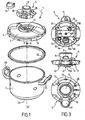
- the cooking apparatus 1 comprises a vessel 2 forming a cooking vessel and preferably having substantially a symmetry of revolution along an axis XX '(cf. figure 1 ).
- the adjective " axial " will refer to the direction of this axis of symmetry X-X 'direction which is similar to the vertical direction when the device is in normal operation.
- the shape of the tank 2 may not be a form of revolution (for example an oval shape), without departing from the scope of the invention.
- the tank 2 is conventionally manufactured from a metallic material such as stainless steel or aluminum, and is preferably provided with a heat-conducting bottom 2A secured to the tank 2 for example by striking at hot.
- the tank 2 may also comprise a gripping member, formed for example by one or more handle (s) 2B, 2C, which are preferably two in number and fixed on the tank 2 diametrically opposite.
- a gripping member formed for example by one or more handle (s) 2B, 2C, which are preferably two in number and fixed on the tank 2 diametrically opposite.
- the apparatus 1 also advantageously comprises a lid 3 intended to be attached and locked on the tank 2 to form with the latter, in cooperation with a seal 30, the cooking chamber.
- the tank 2 and the lid 3 are designed so that the enclosure they form is sufficiently sealed to allow a rise in pressure of the apparatus.
- the lid 3 whose shape is preferably complementary to that of the tank 2 and for example is substantially discoidal, comprises on the one hand an inner face 3A intended to lie opposite the tank 2 when the lid is locked on this last, and secondly an outer face 3B opposite to said inner face 3A, said outer face 3B being intended to be oriented towards the outside of the tank 2, when the tank 2 and the lid 3 form the cooking chamber .
- the lid 3 can be locked or unlocked on the tank 2 by means of locking / unlocking 4.
- the latter can be of any type known to those skilled in the art, and for example consist of a jaw system (corresponding to the variant shown in the figures), segments, bayonets or brackets, this list is not limiting.
- the apparatus 1 comprises a control module 5 intended to be attached to the lid 3, preferably in a removable manner, thanks to a threaded pin 6 cooperating with a hole 7 in the cover 3 and a locking nut 8 to be screwed onto the threaded shaft 6.
- the module 5 carries a series of operating and safety members, such as two control buttons 9, 10 respectively controlling the closing and opening of the locking / unlocking means 4, a removable timer 11, an overpressure safety valve 12, and a sliding finger 13, on the one hand to prevent the device from mounting in pressure in the event of poor closure of the cover, and on the other hand to prevent the opening the lid as long as the pressure in the device is incompatible with the safety of the user.
- operating and safety members such as two control buttons 9, 10 respectively controlling the closing and opening of the locking / unlocking means 4, a removable timer 11, an overpressure safety valve 12, and a sliding finger 13, on the one hand to prevent the device from mounting in pressure in the event of poor closure of the cover, and on the other hand to prevent the opening the lid as long as the pressure in the device is incompatible with the safety of the user.
- the apparatus 1 is provided with a duct 14 allowing the establishment of a vapor leakage flow from the interior of the enclosure to the outside.
- the duct 14 extends from the cover 3 and continues within the module 5 to the outside of the device 1.
- the module 5 comprises a bottom 5A intended to be pressed against the upper face 3B of the cover 3.
- a chamber 15 delimited laterally by an annular seal 15A rising from the bottom 5A and surrounding the volume inside the chamber defined by said chamber 15.
- the chamber 15 communicates with a discharge pipe 16.
- the seal 15A bears against the upper face 3B of the cover 3 , so as to surround a through hole 17 formed in the entire thickness of the cover 3.
- the chamber 15 is placed in sealed communication on the one hand with the interior of the chamber via the orifice 17, and secondly with the outside of the device via the discharge pipe 16, the chamber 15 being interposed between the orifice 17 and the pipe
- the orifice 17 thus forms an orifice for placing the interior of the chamber in communication with the duct 14.
- the duct 14 is formed, in this particular embodiment, by the juxtaposition and the mutual communication of the orifice 17, the chamber 15 and the discharge pipe 16.
- conduit 14 is not limiting, and it is quite conceivable that the conduit 14 is made in another way, particularly in the case where the device does not adopt a design implementing a removable module, such as that illustrated in the figures.
- the conduit 14 defines a first section 18 for steam passage, section 18 through which the steam contained in the chamber to escape to the outside.
- steam is to be taken here in a general sense, that is to say as designating the gas phase or pseudo-gas present within the cooking chamber and cohabiting with the food and the cooking liquid.
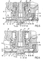
- the apparatus 1 comprises a pressure regulator 19 which may have a regulation configuration (illustrated in FIG. figure 5 ) in which it adjusts the first section 18 to maintain the pressure in the chamber at a predetermined level, corresponding to the operating pressure.
- the predetermined level of pressure is preferably substantially between 55 and 90 kPa.
- the pressure regulating member 19 comprises a valve 20 which, when the regulating member is in regulation configuration, on the one hand closes (that is to say cancels) the first passage section 18 as long as the pressure in the chamber is less than or equal to said predetermined level, and on the other hand releases said first section (i.e., gives it a non-zero value) as soon as that the pressure prevailing in the enclosure exceeds said predetermined level.
- valve 20 is designed to, when in the control configuration, on the one hand prohibit any communication from the inside of the enclosure with the outside as long as the pressure prevailing in the enclosure is less than or equal to the predetermined level and secondly automatically communicate, under the effect of pressure, the interior of the enclosure with the outside as soon as the pressure prevailing in the enclosure exceeds said predetermined level .
- the adjusting member 19 is also likely to have a decompression configuration (illustrated in FIG. figure 6 ) in which it adjusts the first passage section 18 to allow, independently of the pressure in the chamber, placing the interior of the enclosure in communication with the outside.
- the regulating member 19 confers on the first section 18 a non-zero value, maintained substantially permanently (even if the pressure prevailing in the enclosure becomes less than or equal to the level predetermined), to allow the decompression of the device 1, that is to say the balancing of the internal pressure in the cooking chamber with the atmospheric pressure outside the enclosure.
- the pressure adjusting member 19 comprises a valve 20
- the latter thus releases the first passage section 18 when the adjustment member 19 is in the decompression configuration.
- the valve 20 gives the first section 18 a non-zero value, preferably predetermined, allowing the establishment of a vapor leakage flow leading to the decompression of the enclosure.
- the duct 14 further defines a second passage section 21 located upstream of the first passage section 18 in the direction of the leakage flow (that is to say from the inside). from the speaker to the outside).
- the steam contained in the cooking chamber will pass, when it escapes to the outside of the appliance 1 via the duct 14, firstly through the second passage section 21 and then through the first passage section 18, said first and second sections 18, 21 being preferentially distinct and located at a distance from each other, as illustrated in the figures.
- the apparatus 1 comprises an adjustment means 22 for the second passage section 21 designed so that said second passage section 21 has, when the adjustment member 19 is in the regulation configuration (cf. figure 5 ), a first value and, when the regulator is in the decompression configuration (Cf. figure 6 ), a second value substantially lower than the first value.
- the regulator 19 passes from its regulation configuration to its decompression configuration, it corresponds to a decrease in the second passage section 21, which goes from a first value to a second value substantially smaller than the first value.
- the general principle of the invention is therefore based on controlling the value of a second passage section 21 located upstream of the first passage section 18 on which the pressure adjusting member 19 acts. More specifically, the invention is based on the implementation of a larger upstream passage section 21 when the adjustment member 19 is in the regulation configuration only when the latter is in the decompression position. This allows both a high sensitivity regulation, optimizing the exchange of pressure between the control member 19 and the interior of the enclosure, and an optimal control of the speed of the leakage flow when the adjusting member 19 is in the decompression configuration, the restriction of the upstream passage section 21 to prevent the projection of steam and / or hot food material through the conduit 14.
- the second passage section 21 is located substantially towards, and preferably at, the interface between the enclosure and the conduit 14.
- the second passage section 21 defined by the conduit 14 is preferably located as far upstream as possible of said duct 14, facing the direction of the leakage flow, that is to say that the vapor contained in the chamber enters the duct 14 passing firstly through the second section 21.
- the adjustment means 22 of the second passage section 21 is functionally connected to the adjustment member 19 of the pressure inside the enclosure, so that the passage of the adjustment member 19 from its regulation configuration to its decompression configuration causes the value of the second passage section 21 to decrease, from its first value to its second value, and vice versa.
- the adjustment means 22 of the second passage section 21 is carried by the pressure adjusting member 19, as shown in the figures. This thus makes it possible, by means of a single particularly compact subassembly formed by the adjustment member 19 and the adjustment means 22, to perform numerous functions, and notably a control function, a function of decompression, and a function for adjusting the size of the second passage section 21.
- the adjustment means 22 of the second passage section 21 comprises an elongated body 23.
- the latter is preferably of cylindrical shape, and has a first section 23A and a second section 23B with a section greater than that of the first section 23A.
- the elongate body 23 is preferably slidably mounted coaxially with the orifice 17 for putting the interior of the enclosure into communication with the conduit 14, so that when the regulating member 19 is in the regulation configuration, the second passage section 21, which then has its first value, is defined by the cooperation of the first section 23A and the orifice 17 (as illustrated in FIG. figure 5 ), while when the adjusting member 19 is in the decompression configuration, the second section 21, which then has its second value, is defined by the cooperation of the second section 23B and the orifice 17 (as illustrated in FIG. figure 6 ).
- the orifice 17 for placing the interior of the enclosure in communication with the conduit 14 has a circular shape, that is to say that it extends through the the thickness of the cover 3, between the outer face 3B and the inner face 3A of the latter in a cylindrical contour with a circular base axis of symmetry YY ', parallel to the axis X-X'.
- the elongate body 23 is advantageously mounted in translation along the axis Y-Y ', so that it enters the orifice 17 concentrically with the latter.
- the first section 23A and the second section 23B are positioned in the extension of one another and separated by a shoulder, the first section 23A and the second section 23B preferably having a symmetry of revolution about the Y axis. Y '.
- the first section 23A has a smaller radial size than the second section 23B, that is to say that the maximum diameter presented by the first section 23A is smaller than that presented by the second section 23B.
- the second passage section 21 has a shape of a circular ring delimited internally by the first section 23A (or the second section 23B according to the configuration adopted by the adjustment means 19) and externally by the contour of the orifice 17.
- the first passage section 18 has a value that does not substantially exceed the first value of the second passage section 21.
- the second section 18 passage section 21 which then has its first value, is greater than the first section 18 released by the valve 20.
- the first passage section 18 when the adjustment member 19 is in the decompression configuration, has a value that substantially exceeds the second value of the second passage section 21.
- the first section 18 defined by the valve 20 in the decompression configuration is greater than the second passage section 21, which then has its second value.
- the reduced section (second value of the second passage section 21) delimited by the second section 23B and the orifice 17 limits the leakage rate of steam sufficiently to limit the occurrence of an ejection phenomenon water and / or food (phenomenon " Foaming “ also referred to as “ emulsion ”)
- the first section 18 then has a significant predetermined value, greater than that of the second section 21, chosen to allow nonetheless a rapid pressure drop.
- the pressure adjusting member 19 comprises a valve 20
- the latter advantageously comprises a head 24, which is preferably mounted on and at the end of a rod valve 25, which is itself preferably mounted to slide axially along the axis YY 'in the module 5.
- the head 24 preferably extends substantially perpendicular to the axis YY' and advantageously has a generally discoidal shape, as illustrated in the figures.
- the valve 20 also comprises an annular seal 26 rising from the head 24, preferably at the periphery of the latter. This seal 26 is intended, when the valve 20 closes the first passage section 18 (illustrated in FIG.
- the gasket 26 is made of material with the head 24, that is to say that it forms with the latter only one and the same piece in one piece, said piece coming to cap the stem 25.
- the elongated body 23 also rises from the head 24 of the valve 20, in the axial direction X-X '.
- the elongate body 23, the head 24 and the seal 26 are formed by one and the same piece of one piece, which is preferably a cap of material elastomer, for example of the silicone type, intended to be force-fitted on the rod 25.
- the rod 25 is advantageously subjected to the axial return action of a spring 27.
- the spring 27 continuously plates the seal 26 of the head 24 against the outer face 3B of the cover 3, which thus forms a seat for the valve 20, when the adjustment member 19 is in regulation configuration.
- the valve 20 rises, thus releasing the first passage section 18, which automatically regulates the pressure.
- the passage of the adjustment member 19 in decompression configuration corresponds to the exercise of an opposite force and greater than the return force exerted by the spring 27, so as to maintain the first passage section 18 released, which whatever the level of pressure prevailing in the enclosure, to allow the decompression of the latter.
- the ratio of the first value of the second passage section 21 to the second value of the second passage section 21 is substantially between 1.05 and 2.5, and even more preferably between 1.5 and 2.
- the implementation of such section ratios makes it possible to obtain an excellent compromise between the regulation sensitivity on the one hand and the speed and safety of decompression on the other hand.
- the first value of the second passage section 21 is substantially between 10 and 15 mm 2 , and still more preferably substantially equal to 12.4 mm 2
- the second value of the second section of passage 21 is preferably substantially between 5 and 9 mm 2 , and still more preferably is substantially equal to 7.1 mm 2 .
- the user firstly returns the module 5 on the cover 3, by threading the threaded shaft 6 into the corresponding hole 7 formed in the cover 3 and fixing the module 5 with the locking nut 8 screwed onto the threaded spindle 6.
- the annular seal 15A bears against the outer face 3B of the cover 3, thus forming, in cooperation with the orifice 17, the conduit 14.
- the positioning of the module 5 on the cover 3 also causes the penetration of the elongate body 23 in the orifice 17, coaxially with the latter so as to define a second passage section 21 in the form of a circular ring.
- the user has within the tank 2 the food to be cooked, if necessary using a cooking basket (not shown) disposed within the tank 2.
- the user reports the lid 3 equipped with his control module 5 on the tank 2 and locks the device 1 with the jaws 4, the radial displacement of the latter being controlled by the buttons 9, 10.
- the apparatus 1 illustrated in the figures may comprise several indexed regulation sub-configurations, each these sub-configurations of regulation corresponding to a different calibration of the valve 20, made by compressing more or less the spring 27.
- the apparatus 1 is then subjected to the heat of a cooking plate on which it rests.
- the heat released by the cooking plate is transmitted via the bottom 2A to the food arranged inside the cooking chamber formed by the assembly of the tank 2 and the lid 3.
- the pressure prevailing inside the enclosure increases.
- this pressure becomes greater than a predetermined level, corresponding to the calibration of the spring 27, the head 24 and the seal 26 move away from the external face 3B of the cover, which causes a leakage of vapor towards the outside thus allowing the automatic regulation of the pressure.
- This vapor leakage flow first borrows the second passage section 21, then passes through the first passage section 18 located downstream of the second section 21 in the flow direction, then passes through the chamber 15 and s Finally escapes through the discharge pipe 16.
- the head 24 whose diameter directly conditions the bearing surface, has a large diameter, for example a diameter at the seal 26 of 10.5 mm, 33 mm perimeter.
- the second passage section 21 is relatively large, and for example substantially equal to 12.4 mm 2 , so as to allow an excellent exchange of pressure between the inside of the chamber and the exchange surface constituted by the head 24.
- orifice 17 presents advantageously a diameter of 6 mm, while the first section 23A of the elongate body 23 has a diameter substantially equal to 4.5 mm.
- the user can proceed to the decompression of the apparatus by bringing the selector 28 into an indexed decompression position, resulting in the exercise of an opposite axial force and greater than the effort restoring force exerted by the spring 27.
- This makes it possible to raise the valve 20 by a predetermined height, sufficient to ensure a loss of contact of the seal 26 with the external face 3B of the cover 3, thus releasing the first section 18 and causing the second section 23B in cooperation with the orifice 17 to give the second section 21 its second value.
- the valve 20 will be separated as much as possible from its seat formed by the outer face 3B of the lid 3, that is to say that the interstitial space between the outer face 3B of the lid 3 and the seal 26 coming from the head 24 will be as large as possible, its value being chosen according to the second value of the section 21 to obtain a maximum flow without causing the projection of food material and / or hot water towards the outside, through the conduit 14.
- the second section 23B has a diameter substantially equal to 5.2 mm, thus defining with the orifice 17 (whose diameter is preferably equal to substantially 6 mm) a second section passage 21 having a second value substantially equal to 7.1 mm 2 .
- the tests in question were conducted with a device 1 with a tank of capacity equal to six liters, filled to half capacity and placed on a cast iron electric heating plate whose power is 1.5 KW.
- the decompression of the apparatus 1 is effected in 16 seconds to go from an internal pressure of 80 kPa to an internal pressure of 40 kPa when the second section 21 is equal to 12.4 mm 2 , while it takes 26 seconds when this section is equal to 7.1 mm 2 , all things being equal.
- the regulation fineness which corresponds to the difference between the trigger value (that is to say, the opening of the first section 18) of the valve 20 and the maximum regulation value is 4 kPa when the first section is substantially equal to 12.4 mm 2 , while it is substantially equal to 6 kPa when said second section 21 is substantially equal to 7.1 mm 2 , all things being equal elsewhere.
- the seal 26 should be spaced from the outer face 3B of the cover 3 of a distance of 0.2 mm (with a diameter of the joint 26 of 10.5 mm, which corresponds to a perimeter of 33 mm).
- the manufacturing tolerances do not allow such a spreading accuracy to be obtained, so that there is a risk of violent decompression (if the spacing distance s is actually greater than 0.2 mm because of manufacturing tolerances) or lack of sufficient decompression (if the spacing distance is actually less than 0.2 mm because of manufacturing tolerances).
- the invention makes it possible, by driving a section 21 situated upstream of the section 18 set by the regulation valve, to overcome the constraints relating to manufacturing tolerances, by allowing a distance much greater than 0.2. mm without favoring the appearance of violent exhaust phenomena.
Abstract
Description
La présente invention se rapporte au domaine technique général des appareils de cuisson d'aliments, en particulier de nature domestique, destinés à former une enceinte de cuisson étanche, au sein de laquelle sont cuits des aliments sous pression de vapeur.The present invention relates to the general technical field of food cooking appliances, in particular of domestic nature, intended to form a sealed cooking chamber, in which are cooked foods under steam pressure.
La présente invention concerne plus particulièrement un appareil de cuisson d'aliments sous pression agencé pour former une enceinte de cuisson, pourvu d'un conduit permettant l'établissement d'un écoulement de fuite de vapeur de l'intérieur de l'enceinte vers l'extérieur et définissant une première section de passage de vapeur, ledit appareil comprenant un organe de réglage de la pression susceptible de présenter d'une part une configuration de régulation, dans laquelle il règle la première section de passage pour maintenir la pression régnant dans l'enceinte à un niveau prédéterminé, et d'autre part une configuration de décompression, dans laquelle il règle la première section de passage pour permettre, indépendamment du niveau de la pression régnant dans l'enceinte, la mise en communication de l'intérieur de l'enceinte avec l'extérieur, ledit conduit définissant en outre une seconde section de passage située à l'amont de la première section dans le sens de l'écoulement de fuite.The present invention more particularly relates to a food cooking apparatus under pressure arranged to form a cooking chamber, provided with a conduit for the establishment of a vapor leakage flow from the inside of the enclosure to the chamber. and defining a first vapor passage section, said apparatus comprising a pressure regulating member capable of having on the one hand a regulation configuration, in which it adjusts the first passage section to maintain the pressure prevailing in the enclosure at a predetermined level, and secondly a decompression configuration, in which it adjusts the first passage section to allow, regardless of the level of pressure in the chamber, the communication of the interior of the the enclosure with the outside, said duct further defining a second passage section located upstream of the first section in the direction leakage flow.
Les appareils de cuisson sous pression, en particulier à usage domestique, du genre autocuiseur, sont bien connus dans l'art antérieur. De tels appareils comprennent généralement une cuve et un couvercle destiné à être rapporté sur la cuve pour former une enceinte de cuisson hermétique au sein de laquelle sont placés les aliments à cuire.Pressurized cooking appliances, in particular for domestic use, of the pressure cooker type, are well known in the prior art. Such devices generally comprise a tank and a lid intended to be attached to the tank to form a sealed cooking chamber in which are placed the food to be cooked.
Cette enceinte peut ainsi atteindre des pressions et températures élevées lorsque l'appareil est soumis à l'influence d'une source de chauffe.This chamber can thus achieve high pressures and temperatures when the device is subjected to the influence of a heating source.
De tels appareils sont en outre généralement pourvus d'une soupape de régulation permettant de maintenir la pression régnant au sein de l'enceinte à un niveau prédéterminé, habituellement désigné par l'appellation « pression de fonctionnement ».Such devices are also generally provided with a control valve to maintain the pressure within the chamber at a predetermined level, usually referred to as the "operating pressure ".
Les effets conjugués des niveaux élevés de pression et de température atteints dans ces appareils connus permettent ainsi de réaliser une cuisson des aliments extrêmement rapide, tout en étant respectueuse des propriétés organoleptiques et nutritionnelles des aliments.The combined effects of the high levels of pressure and temperature reached in these known devices thus allow cooking food extremely fast, while being respectful of organoleptic and nutritional properties of food.
Afin que l'utilisateur puisse ouvrir le couvercle, il est nécessaire de décompresser au préalable l'appareil, la pression de fonctionnement étant en effet, du fait de son niveau élevé, incompatible avec une ouverture sécurisée, c'est à dire sans risque d'échappement brutal du couvercle sous l'effet de la pression.So that the user can open the lid, it is necessary to decompress the device beforehand, the operating pressure is indeed, because of its high level, incompatible with a secure opening, ie without risk of sudden escape of the lid under the effect of pressure.
Pour décompresser un appareil de cuisson conforme à l'art antérieur, il existe plusieurs façons de procéder.To decompress a cooking appliance according to the prior art, there are several ways to proceed.
Selon une première méthode, il est possible de placer l'appareil sous un jet d'eau froide. Une telle solution est cependant peu satisfaisante, car elle implique de mouiller abondamment la surface externe de l'appareil, avec tous les inconvénients que cela engendre pour l'utilisateur. Une telle méthode de décompression s'avère également relativement malaisée à exécuter par l'utilisateur, car elle nécessite le déplacement de l'appareil lourd et brûlant, avec tout l'inconfort et le risque afférents, vers un point d'eau.According to a first method, it is possible to place the apparatus under a stream of cold water. Such a solution is unsatisfactory, however, because it involves abundantly wetting the outer surface of the device, with all the disadvantages that this entails for the user. Such a method of decompression is also relatively difficult to perform by the user because it requires moving the heavy and burning device, with all the discomfort and risk, to a water point.
En outre, une telle méthode peut conduire, pour certains appareils du moins, à une mise en dépression interne de l'appareil, qui empêche la séparation de la cuve et du couvercle.In addition, such a method can lead, for some devices at least, to an internal depression of the device, which prevents the separation of the tank and lid.
Une méthode alternative consiste à agir sur la soupape de régulation de l'appareil, de façon à mettre en communication de manière forcée l'intérieur de l'enceinte avec l'extérieur.An alternative method is to act on the regulating valve of the apparatus, so as to forcibly communicate the interior of the chamber with the outside.
On connaît ainsi des appareils pourvus d'une part d'un orifice circulaire ménagé dans le couvercle, et d'autre part d'une soupape de régulation à ressort comprenant une tête circulaire, de diamètre supérieur à celle de l'orifice et à partir de laquelle s'élève, à sa périphérie, un joint d'étanchéité annulaire. Le joint d'étanchéité annulaire est destiné à venir en appui étanche contre le couvercle sous l'action du ressort, de manière à entourer l'orifice et former ainsi avec la tête une chambre hermétique coiffant l'orifice pour empêcher toute fuite de vapeur vers l'extérieur. Lorsque la pression régnant dans l'enceinte dépasse une valeur prédéterminée, la tête et son joint sont repoussés à distance de l'orifice, contre l'action du ressort, ce qui permet ainsi une régulation automatique de la pression régnant dans l'enceinte.Devices are thus known provided on the one hand with a circular orifice formed in the lid, and on the other hand with a spring-loaded regulating valve comprising a circular head, of diameter greater than that of the orifice and from of which rises, at its periphery, an annular seal. The annular seal is intended to bear tightly against the lid under the action of the spring, so as to surround the orifice and thus form with the head a sealed chamber capping the orifice to prevent any escape of steam towards outside. When the pressure in the chamber exceeds a predetermined value, the head and its seal are pushed away from the orifice against the action of the spring, thereby allowing automatic regulation of the pressure in the chamber.
Ces appareils connus sont également dotés d'un moyen de manoeuvre de la soupape de régulation permettant, quel que soit le niveau de pression régnant dans l'enceinte, de forcer la soupape dans une position d'ouverture, dans laquelle la tête et son joint sont repoussés à distance de l'orifice, ce qui permet la décompression de l'appareil.These known apparatuses are also provided with means for operating the control valve making it possible, whatever the level of pressure in the chamber, to force the valve into an open position, in which the head and its seal are pushed away from the orifice, which allows decompression of the device.
Ces appareils connus permettent ainsi de remplir une double fonction à l'aide de la soupape de régulation, savoir une fonction de régulation proprement dite et une fonction de décompression.These known apparatuses thus make it possible to fulfill a dual function by means of the regulation valve, namely a regulation function itself and a decompression function.
Un tel appareil est connu du document
Afin d'obtenir une bonne qualité de régulation, il est nécessaire que la soupape de régulation soit extrêmement sensible à l'évolution de la pression au sein de l'enceinte, de manière à pouvoir réagir rapidement à d'éventuelles fluctuations de pression à l'intérieur de l'enceinte. A cette fin, il est nécessaire que la surface de la portée de la soupape, c'est-à-dire la surface d'échange de pression entre la soupape et l'intérieur de l'enceinte, soit la plus grande possible. Cela signifie que la tête de soupape doit présenter un diamètre le plus important possible, dans la limite des contraintes d'encombrement et de faisabilité technique.In order to obtain a good quality of regulation, it is necessary that the regulation valve is extremely sensitive to the evolution of the pressure within the enclosure, so as to be able to react quickly to possible pressure fluctuations in the chamber. inside the enclosure. To this end, it is necessary that the surface of the valve seat, that is to say the pressure exchange surface between the valve and the interior of the enclosure, be as large as possible. This means that the valve head must have the largest possible diameter, within the constraints of space and technical feasibility.
Toutefois, la mise en oeuvre d'une surface de portée importante, c'est-à-dire d'une tête de soupape présentant un diamètre important, génère des inconvénients non négligeables en ce qui concerne la décompression. En effet, afin de garantir une décompression complète et compte-tenu des tolérances de fabrication des différentes pièces en jeu, il est nécessaire d'écarter la tête de l'orifice d'une distance relativement importante. Or, la conjugaison d'une grande distance d'écartement avec un diamètre important de la tête conduit à mettre en place une section de fuite particulièrement importante lors de la décompression.However, the implementation of a large span surface, that is to say a valve head having a large diameter, generates significant disadvantages with respect to decompression. Indeed, to ensure complete decompression and taking into account the manufacturing tolerances of the various parts involved, it is necessary to move the head of the orifice a relatively large distance. However, the combination of a large spacing distance with a large diameter of the head leads to set up a particularly large leakage section during decompression.
La libération d'une section de fuite importante permet certes une décompression rapide, en générant un débit important de vapeur. Cependant, ce débit de vapeur et la chute de pression afférente sont si importants et brusques que cela peut générer un phénomène de moussage des aliments contenus dans le récipient (phénomène parfois également désigné dans le métier par le terme « émulsion ») qui conduit à une éjection violente, par l'orifice, d'eau et/ou d'aliments brûlants.The release of a large leakage section certainly allows rapid decompression, generating a large flow of steam. However, this flow of steam and the pressure drop afferent are so large and abrupt that it can cause a phenomenon of foaming food contained in the container (a phenomenon sometimes also referred to in the art by the term " emulsion ") which leads to a violent ejection, through the orifice, of water and / or burning food.
Afin d'éviter l'apparition d'un tel phénomène désagréable et dangereux, les appareils connus mettent donc en oeuvre soit un orifice de section réduite, ce qui nuit à la sensibilité de décompression, soit des éléments de protection, du genre crépine, qui perturbent l'écoulement tant en décompression qu'en régulation.In order to avoid the occurrence of such an unpleasant and dangerous phenomenon, the known apparatuses therefore use either a reduced-section orifice, which is detrimental to the decompression sensitivity, or elements of protection, strainer type, which disturb the flow both decompression and regulation.
Il existe donc un besoin pour un appareil de cuisson sous pression qui permette à la fois une excellente qualité de régulation et une excellente maîtrise de la décompression, sans sacrifier l'une ou l'autre de ces deux fonctions.There is therefore a need for a pressure cooker that allows both excellent control quality and excellent decompression control without sacrificing either of these two functions.
Les objets assignés à l'invention visent en conséquence à proposer un nouvel appareil de cuisson d'aliments sous pression portant remède aux différents inconvénients de l'art antérieur énumérés précédemment et qui offre un excellent compromis entre la qualité de régulation d'une part et l'efficacité et la sûreté de décompression d'autre part, tout en étant de conception très simple et économique.The objects assigned to the invention therefore aim at proposing a novel pressure food cooking appliance which remedies the various disadvantages of the prior art listed above and which offers an excellent compromise between the quality of regulation on the one hand and the efficiency and safety of decompression on the other hand, while being very simple and economical design.
Un autre objet de l'invention vise à proposer un nouvel appareil de cuisson d'aliments sous pression permettant, lors de sa décompression, de limiter efficacement les perturbations du flux de fuite de vapeur.Another object of the invention is to propose a new device for cooking pressurized food allowing, during its decompression, to effectively limit the disturbances of the vapor leakage flow.
Un autre objet de l'invention vise à proposer un nouvel appareil de cuisson d'aliments sous pression de construction particulièrement compacte.Another object of the invention is to propose a new apparatus for cooking food under pressure of particularly compact construction.
Un autre objet de l'invention vise à proposer un nouvel appareil de cuisson d'aliments sous pression de construction particulièrement simplifiée autorisant un fonctionnement très fiable.Another object of the invention is to propose a new pressure food cooking appliance of particularly simplified construction allowing a very reliable operation.
Un autre objet de l'invention vise à proposer un nouvel appareil de cuisson d'aliments sous pression dont la conception repose sur des principes éprouvés.Another object of the invention is to propose a new device for cooking food under pressure whose design is based on proven principles.
Un autre objet de l'invention vise à proposer un nouvel appareil de cuisson d'aliments sous pression qui est capable d'assurer une régulation de pression particulièrement fine.Another object of the invention is to propose a new device for cooking food under pressure which is capable of providing a particularly fine pressure regulation.
Un autre objet de l'invention vise à proposer un nouvel appareil de cuisson d'aliments sous pression permettant un excellent contrôle du flux de décompression.Another object of the invention is to propose a new device for cooking food under pressure allowing excellent control of the decompression flow.
Un autre objet de l'invention vise à proposer un nouvel appareil de cuisson d'aliments sous pression construit à partir d'un nombre minimum de pièces.Another object of the invention is to provide a new pressure food cooking appliance constructed from a minimum number of parts.
Un autre objet de l'invention vise à proposer un nouvel appareil domestique de cuisson d'aliments sous pression dont la décompression est particulièrement rapide et sécurisée, tout en présentant une excellente sensibilité de régulation.Another object of the invention is to propose a new domestic appliance for cooking food under pressure whose decompression is particularly rapid and secure, while having excellent control sensitivity.
Les objets assignés à l'invention sont atteints à l'aide d'un appareil de cuisson d'aliments sous pression agencé pour former une enceinte de cuisson, pourvu d'un conduit permettant l'établissement d'un écoulement de fuite de vapeur de l'intérieur de l'enceinte vers l'extérieur et définissant une première section de passage de vapeur, ledit appareil comprenant un organe de réglage de la pression susceptible de présenter d'une part une configuration de régulation, dans laquelle il règle la première section de passage pour maintenir la pression régnant dans l'enceinte à un niveau prédéterminé, et d'autre part une configuration de décompression, dans laquelle il règle la première section de passage pour permettre, indépendamment du niveau de la pression régnant dans l'enceinte, la mise en communication de l'intérieur de l'enceinte avec l'extérieur, ledit conduit définissant en outre une seconde section de passage située à l'amont de la première section dans le sens de l'écoulement de fuite, ledit appareil étant caractérisé en ce qu'il comprend un moyen d'ajustement de la deuxième section de passage conçu pour que cette dernière présente, lorsque l'organe de réglage est en configuration de régulation, une première valeur et, lorsque l'organe de réglage est en configuration de décompression, une deuxième valeur sensiblement inférieure à la première valeur.The objects assigned to the invention are achieved by means of a pressurized food cooking apparatus arranged to form a cooking chamber, provided with a duct allowing the establishment of a steam leakage flow of the interior of the enclosure to the outside and defining a first section for the passage of steam, said apparatus comprising a pressure regulating member capable of presenting on the one hand a regulation configuration, in which it regulates the first section; passage to maintain the pressure prevailing in the chamber to a predetermined level, and secondly a decompression configuration, wherein it regulates the first passage section to allow, regardless of the level of pressure in the chamber, placing the interior of the enclosure in communication with the outside, said duct further defining a second passage section located upstream of the first section in the direction of leakage flow, said apparatus being characterized in that it comprises means for adjusting the second passage section designed so that the latter has, when the regulator is in regulation configuration, a first value and, when the regulator is in the decompression configuration, a second value substantially less than the first value.
D'autres particularités et avantages de l'invention apparaîtront et ressortiront plus en détails à la lecture de la description faite ci-après, en référence aux dessins, annexés donnés à titre purement illustratif et non limitatif, dans lesquels :
- la
figure 1 illustre, selon une vue générale éclatée en perspective, un appareil de cuisson conforme à l'invention. - La
figure 2 illustre, selon une vue schématique en perspective, le couvercle de l'appareil de lafigure 1 . - La
figure 3 illustre, selon des vues (de haut en bas) de dessous, de côté et de dessus, un module de commande incorporant l'organe de réglage de pression de l'appareil et destiné à être rapporté et fixé de façon amovible sur le couvercle illustré à lafigure 2 . - La
figure 4 illustre, selon une vue schématique en perspective, un détail de réalisation en coupe du module représenté à lafigure 3 . - La
figure 5 représente un détail de l'organe de réglage de la pression, lorsque ce dernier présente sa configuration de régulation. - La
figure 6 représente un détail de l'organe de réglage de la pression, lorsque ce dernier présente sa configuration de décompression.
- the
figure 1 illustrates, in a general perspective exploded view, a cooking appliance according to the invention. - The
figure 2 illustrates, in a schematic perspective view, the cover of the apparatus of thefigure 1 . - The
figure 3 illustrates, in top (bottom), side and top views, a control module incorporating the pressure regulating member of the apparatus and adapted to be attached and releasably attached to the illustrated lid; to thefigure 2 . - The
figure 4 illustrates, in a schematic perspective view, a detail of sectional realization of the module shown in FIG.figure 3 . - The
figure 5 represents a detail of the pressure regulating member, when the latter presents its regulation configuration. - The
figure 6 represents a detail of the pressure regulating member when the latter presents its decompression configuration.
L'appareil de cuisson d'aliments 1 sous pression conforme à l'invention est destiné à assurer la cuisson de différents aliments, sous pression de vapeur, de préférence dans un contexte domestique.The pressurized food cooking apparatus 1 according to the invention is intended for cooking different foods under steam pressure, preferably in a domestic context.
De façon préférentielle, l'appareil de cuisson 1 conforme à l'invention est constitué par un autocuiseur domestique. Pour des raisons de simplicité de description, il sera exclusivement fait référence dans ce qui suit, en relation avec les dessins annexés, à un appareil 1 constitué par un autocuiseur domestique, étant entendu que l'invention peut également éventuellement concerner des appareils de type professionnel ou semi-professionnel.Preferably, the cooking apparatus 1 according to the invention consists of a domestic pressure cooker. For the sake of simplicity of description, reference will be made hereinafter exclusively, in connection with the accompanying drawings, to an apparatus 1 constituted by a domestic pressure cooker, it being understood that the invention may also possibly relate to professional type appliances. or semi-professional.
De façon classique, l'appareil 1 conforme à l'invention est agencé pour former une enceinte de cuisson, laquelle est de préférence sensiblement étanche et destinée à être soumise à l'action d'une source de chauffe, que cette dernière soit externe (par exemple : plaque de cuisson) ou interne (par exemple : résistance électrique embarquée).Conventionally, the apparatus 1 according to the invention is designed to form a cooking chamber, which is preferably substantially sealed and intended to be subjected to the action of a heating source, the latter being external ( for example: cooking plate) or internal (for example: on-board electrical resistance).
Avantageusement, l'appareil de cuisson 1 conforme à l'invention comprend une cuve 2 formant récipient de cuisson et présentant de façon préférentielle sensiblement une symétrie de révolution selon un axe X-X' (cf.
La cuve 2 peut également comporter un organe de préhension, formé par exemple par une ou plusieurs poignée(s) 2B, 2C, lesquelles sont préférentiellement au nombre de deux et fixées sur la cuve 2 de façon diamétralement opposée.The tank 2 may also comprise a gripping member, formed for example by one or more handle (s) 2B, 2C, which are preferably two in number and fixed on the tank 2 diametrically opposite.
L'appareil 1 conforme à l'invention comprend également avantageusement un couvercle 3 destiné à être rapporté et verrouillé sur la cuve 2 pour former avec cette dernière, en coopération avec un joint d'étanchéité 30, l'enceinte de cuisson. La cuve 2 et le couvercle 3 sont conçus de façon que l'enceinte qu'ils forment soit suffisamment hermétique pour permettre une montée en pression de l'appareil.The apparatus 1 according to the invention also advantageously comprises a
Le couvercle 3, dont la forme est de préférence complémentaire à celle de la cuve 2 et par exemple est sensiblement discoïde, comprend d'une part une face interne 3A destinée à se trouver en regard de la cuve 2 lorsque le couvercle est verrouillé sur cette dernière, et d'autre part une face externe 3B opposée à ladite face interne 3A, ladite face externe 3B étant destinée à être orientée vers l'extérieur de la cuve 2, lorsque la cuve 2 et le couvercle 3 forment l'enceinte de cuisson. Le couvercle 3 peut être verrouillé ou déverrouillé sur la cuve 2 grâce à un moyen de verrouillage / déverrouillage 4. Ce dernier peut être de tout type connu de l'homme du métier, et par exemple être constitué d'un système à mâchoires (correspondant à la variante représentée aux figures), à segments, à baïonnettes ou encore à étriers, cette liste n'étant nullement limitative.The
De façon purement optionnelle mais préférentielle, tel que cela est illustré aux figures, l'appareil 1 comprend un module de commande 5 destiné à être rapporté sur le couvercle 3, de préférence de façon amovible, grâce à un axe fileté 6 coopérant avec un trou 7 ménagé dans le couvercle 3 et un écrou de blocage 8 destiné à être vissé sur l'axe fileté 6.In a purely optional but preferential manner, as is illustrated in the figures, the apparatus 1 comprises a
Dans la variante illustrée aux figures, le module 5 embarque une série d'organes de fonctionnement et de sécurité, tels que deux boutons de commande 9, 10 commandant respectivement la fermeture et l'ouverture du moyen de verrouillage / déverrouillage 4, un minuteur amovible 11, une soupape de sécurité à la surpression 12, ainsi qu'un doigt coulissant 13 permettant d'une part d'empêcher l'appareil de monter en pression en cas de mauvaise fermeture du couvercle, et d'autre part d'empêcher l'ouverture du couvercle tant que la pression régnant dans l'appareil est incompatible avec la sécurité de l'utilisateur. Ces différents organes de commande et de sécurité sont bien connus en tant que tels et ne seront donc pas décrits plus en détails ici.In the variant illustrated in the figures, the
Conformément à l'invention, l'appareil 1 est pourvu d'un conduit 14 permettant l'établissement d'un écoulement de fuite de vapeur de l'intérieur de l'enceinte vers l'extérieur. Selon la conception mise en oeuvre dans la variante illustrée aux figures, le conduit 14 s'étend à partir du couvercle 3 et se poursuit au sein du module 5 jusque vers l'extérieur de l'appareil 1. Ainsi, de manière préférentielle, le module 5 comprend un fond 5A destiné à être plaqué contre la face supérieure 3B du couvercle 3. Sur le fond 5A est ménagée une chambre 15 délimitée latéralement par un joint d'étanchéité annulaire 15A s'élevant à partir du fond 5A et entourant le volume intérieur délimité par ladite chambre 15. La chambre 15 communique avec un tuyau d'évacuation 16. Lorsque le module 5 est rapporté et fixé sur le couvercle 3, le joint d'étanchéité 15A vient en appui étanche contre la face supérieure 3B du couvercle 3, de manière à entourer un orifice traversant 17 ménagé dans toute l'épaisseur du couvercle 3. Ainsi, lorsque le module 5 est mis en place sur le couvercle 3, la chambre 15 est mise en communication étanche d'une part avec l'intérieur de l'enceinte par l'intermédiaire de l'orifice 17, et d'autre part avec l'extérieur de l'appareil par l'intermédiaire du tuyau d'évacuation 16, la chambre 15 étant interposée entre l'orifice 17 et le tuyau d'évacuation 16. L'orifice 17 forme ainsi un orifice de mise en communication de l'intérieur de l'enceinte avec le conduit 14. Le conduit 14 est quant à lui formé, dans ce mode de réalisation particulier, par la juxtaposition et la mise en communication mutuelle de l'orifice 17, de la chambre 15 et du tuyau d'évacuation 16.According to the invention, the apparatus 1 is provided with a
Bien évidemment, cet exemple de réalisation du conduit 14 n'est pas limitatif, et il est tout à fait envisageable que le conduit 14 soit réalisé d'une autre manière, en particulier dans le cas où l'appareil n'adopte pas une conception mettant en oeuvre un module amovible, telle que celle illustrée aux figures.Of course, this embodiment of the
Conformément à l'invention, le conduit 14 définit une première section 18 de passage de vapeur, section 18 par laquelle passe la vapeur contenue dans l'enceinte pour s'échapper vers l'extérieur.According to the invention, the
Le terme « vapeur » doit être pris ici dans un sens général, c'est-à-dire comme désignant la phase gazeuse ou pseudo-gazeuse présente au sein de l'enceinte de cuisson et cohabitant avec les aliments et le liquide de cuisson.The term " steam " is to be taken here in a general sense, that is to say as designating the gas phase or pseudo-gas present within the cooking chamber and cohabiting with the food and the cooking liquid.
Conformément à l'invention, l'appareil 1 comprend un organe de réglage 19 de la pression susceptible de présenter une configuration de régulation (illustrée à la
En d'autres termes, l'organe de réglage 19 de la pression est conçu pour ajuster la taille de la première section 18 en fonction de la pression instantanée régnant dans l'enceinte pour :
- soit autoriser une fuite de vapeur par la première
section 18 si la pression instantanée est supérieure au niveau prédéterminé, - soit empêcher toute fuite de vapeur par la première
section 18 si la pression instantanée régnant dans l'enceinte est inférieure au niveau prédéterminé, de façon à permettre la montée (ou la limitation) en pression de l'appareil 1.
- allow a vapor leakage by the
first section 18 if the instantaneous pressure is higher than the predetermined level, - or prevent any leakage of steam by the
first section 18 if the instantaneous pressure in the chamber is below the predetermined level, so as to allow the rise (or limitation) in pressure of the apparatus 1.
De manière préférentielle et connue en tant que telle, l'organe de réglage 19 de la pression comprend une soupape 20 qui, lorsque l'organe de réglage est en configuration de régulation, d'une part obture (c'est-à-dire annule) la première section de passage 18 tant que la pression régnant dans l'enceinte est inférieure ou égale audit niveau prédéterminé, et d'autre part libère ladite première section (c'est-à-dire lui confère une valeur non nulle) dès que la pression régnant dans l'enceinte dépasse ledit niveau prédéterminé. En d'autres termes, la soupape 20 est conçue pour, lorsqu'elle se trouve en configuration de régulation, d'une part interdire toute communication de l'intérieur de l'enceinte avec l'extérieur tant que la pression régnant dans l'enceinte est inférieure ou égale au niveau prédéterminé et d'autre part mettre automatiquement en communication, sous l'effet de la pression, l'intérieur de l'enceinte avec l'extérieur dès que la pression régnant dans l'enceinte dépasse ledit niveau prédéterminé.Preferably and known as such, the
Conformément à l'invention, l'organe de réglage 19 est également susceptible de présenter une configuration de décompression (illustrée à la
Dans le cas préférentiel illustré aux figures où l'organe de réglage de la pression 19 comprend une soupape 20, cette dernière libère donc la première section de passage 18 lorsque l'organe de réglage 19 est en configuration de décompression. Cela signifie que la soupape 20 confère à la première section 18 une valeur non nulle, de préférence prédéterminée, permettant l'établissement d'un flux de fuite de vapeur conduisant à la décompression de l'enceinte.In the preferred case illustrated in the figures where the
Conformément à l'invention, le conduit 14 définit en outre une seconde section de passage 21 située à l'amont de la première section de passage 18 dans le sens l'écoulement de fuite (c'est-à-dire de l'intérieur de l'enceinte vers l'extérieur). En d'autres termes, la vapeur contenue dans l'enceinte de cuisson passera, lorsqu'elle s'échappera vers l'extérieur de l'appareil 1 par le conduit 14, tout d'abord par la seconde section de passage 21 puis par la première section de passage 18, lesdites première et deuxième sections 18, 21 étant préférentiellement distinctes et situées à distance l'une de l'autre, comme cela est illustré aux figures.According to the invention, the
Conformément à l'invention, l'appareil 1 comprend un moyen d'ajustement 22 de la deuxième section de passage 21 conçu pour que ladite deuxième section de passage 21 présente, lorsque l'organe de réglage 19 est en configuration de régulation (cf.
Le principe général de l'invention repose donc sur le pilotage de la valeur d'une deuxième section de passage 21 située à l'amont de la première section de passage 18 sur laquelle agit l'organe de réglage 19 de la pression. Plus précisément, l'invention repose sur la mise en oeuvre d'une section de passage amont 21 plus importante lorsque l'organe de réglage 19 est en configuration de régulation que lorsque ce dernier est en position de décompression. Cela permet à la fois une grande sensibilité de régulation, en optimisant l'échange de pression entre l'organe de réglage 19 et l'intérieur de l'enceinte, ainsi qu'un contrôle optimal de la vitesse du flux de fuite lorsque l'organe de réglage 19 est en configuration de décompression, la restriction de la section de passage amont 21 permettant d'éviter les projections de vapeur et/ou de matière alimentaire brûlante par le conduit 14.The general principle of the invention is therefore based on controlling the value of a
Avantageusement, la deuxième section de passage 21 est située sensiblement vers, et de préférence à, l'interface entre l'enceinte et le conduit 14. En d'autres termes, la deuxième section de passage 21 définie par le conduit 14 est préférentiellement située le plus à l'amont possible dudit conduit 14, en regard du sens de l'écoulement de fuite, c'est-à-dire que la vapeur contenue dans l'enceinte entre dans le conduit 14 en passant en premier lieu par la deuxième section 21. Cette mesure technique permet de générer une restriction du débit du flux de fluide de vapeur au plus près de l'intérieur de l'enceinte, ce qui permet de minimiser les perturbations d'écoulement du flux et de conserver ainsi un écoulement sensiblement constant et maîtrisé lors de la décompression.Advantageously, the
Avantageusement, le moyen d'ajustement 22 de la deuxième section de passage 21 est relié fonctionnellement à l'organe de réglage 19 de la pression régnant à l'intérieur de l'enceinte, de façon que le passage de l'organe de réglage 19 de sa configuration de régulation à sa configuration de décompression entraîne la diminution de la valeur de la deuxième section de passage 21, de sa première valeur à sa deuxième valeur, et réciproquement.Advantageously, the adjustment means 22 of the
De façon encore plus préférentielle, le moyen d'ajustement 22 de la deuxième section de passage 21 est porté par l'organe de réglage 19 de la pression, tel que cela est illustré aux figures. Cela permet ainsi, à l'aide d'un unique sous-ensemble particulièrement compact formé par l'organe de réglage 19 et le moyen d'ajustement 22, d'assurer de nombreuses fonctions, et notamment une fonction de régulation, une fonction de décompression, et une fonction de réglage de la taille de la deuxième section de passage 21.Even more preferably, the adjustment means 22 of the
Avantageusement, le moyen d'ajustement 22 de la deuxième section de passage 21 comprend un corps allongé 23. Ce dernier est de préférence de forme cylindrique, et présente un premier tronçon 23A et un deuxième tronçon 23B de section supérieure à celle du premier tronçon 23A. Le corps allongé 23 est de préférence monté à coulissement coaxialement à l'orifice 17 de mise en communication de l'intérieur de l'enceinte avec le conduit 14, de façon que lorsque l'organe de réglage 19 est en configuration de régulation, la deuxième section de passage 21, qui présente alors sa première valeur, est définie par la coopération du premier tronçon 23A et de l'orifice 17 (tel que cela est illustré à la
Dans le mode de réalisation illustré aux figures, l'orifice 17 de mise en communication de l'intérieur de l'enceinte avec le conduit 14 présente une forme circulaire, c'est-à-dire qu'il s'étend à travers l'épaisseur du couvercle 3, entre la face externe 3B et la face interne 3A de ce dernier selon un contour cylindrique à base circulaire d'axe de symétrie Y-Y', parallèle à l'axe X-X'. Le corps allongé 23 est avantageusement monté à translation selon l'axe Y-Y', de telle sorte qu'il pénètre dans l'orifice 17 concentriquement à ce dernier. Le premier tronçon 23A et le deuxième tronçon 23B sont positionnés dans le prolongement l'un de l'autre et séparés par un épaulement, le premier tronçon 23A et le deuxième tronçon 23B présentant de préférence une symétrie de révolution autour de l'axe Y-Y'. Le premier tronçon 23A présente un encombrement radial inférieur à celui du deuxième tronçon 23B, c'est-à-dire que le diamètre maximal présenté par le premier tronçon 23A est inférieur à celui présenté par le deuxième tronçon 23B. Ainsi, dans le cas du mode de réalisation illustré aux figures, la deuxième section de passage 21 présente une forme de couronne circulaire délimitée intérieurement par le premier tronçon 23A (ou le deuxième tronçon 23B selon la configuration adoptée par le moyen de réglage 19) et extérieurement par le contour de l'orifice 17.In the embodiment illustrated in the figures, the
Dans l'exemple illustré aux figures, la première valeur S1 présentée par la deuxième section de passage 21 peut donc être obtenue par la formule : S1 = π L1 (2R - L1) où R est le rayon de l'orifice 17 et L1 est la largeur de l'espace interstitiel annulaire délimité par l'orifice 17 et le premier tronçon 23A. De la même façon, la deuxième valeur S2 de la deuxième section de passage 21 peut être obtenue par la formule : S2 = π L2 (2R - L2) où R est le rayon de l'orifice 17 et L2 est la largeur de l'espace interstitiel annulaire délimité par l'orifice 17 et le deuxième tronçon 23B.In the example illustrated in the figures, the first value S 1 presented by the
Avantageusement, lorsque l'organe de réglage 19 est en configuration de régulation et qu'il libère la première section 18, afin de ramener la pression régnant dans l'enceinte au niveau prédéterminé correspondant à la pression de fonctionnement, la première section de passage 18 présente une valeur qui n'excède sensiblement pas la première valeur de la deuxième section de passage 21. En d'autres termes, lorsque l'organe de réglage 19 libère la première section 18 alors qu'il est en configuration de régulation, la deuxième section de passage 21, qui présente alors sa première valeur, est supérieure à la première section 18 libérée par la soupape 20. Cette mesure technique évite tout phénomène intempestif de remontée en pression au sein du conduit 14 pendant la régulation, qui pourrait nuire à la précision et à la rapidité de cette dernière.Advantageously, when the regulating
Avantageusement, lorsque l'organe de réglage 19 est en configuration de décompression, la première section de passage 18 présente une valeur qui excède sensiblement la deuxième valeur de la deuxième section de passage 21. En d'autres termes, la première section 18 définie par la soupape 20 en configuration de décompression est supérieure à la deuxième section de passage 21, laquelle présente alors sa seconde valeur. Cette mesure technique permet un excellent compromis entre deux fonctions fondamentales, savoir la rapidité de décompression d'une part qui permet à l'utilisateur d'ouvrir rapidement son appareil 1 et la sécurité d'utilisation d'autre part qui évite toute projection dangereuse de matière alimentaire et/ou de liquide brûlant. En effet, la section réduite (deuxième valeur de la deuxième section de passage 21) délimitée par le deuxième tronçon 23B et l'orifice 17 limite le débit de fuite de vapeur de manière suffisante pour limiter l'apparition d'un phénomène d'éjection d'eau et/ou d'aliments (phénomène de « moussage » également désigné sous l'appellation « émulsion »), tandis que la première section 18 présente alors une valeur prédéterminée importante, supérieure à celle de la deuxième section 21, choisie pour autoriser néanmoins une chute de pression rapide.Advantageously, when the
Dans le cas correspondant aux modes de réalisation illustrés aux figures, où l'organe de réglage 19 de la pression comprend une soupape 20, cette dernière comprend avantageusement une tête 24, laquelle est de préférence montée sur et à l'extrémité d'une tige de soupape 25, laquelle est elle-même préférentiellement montée à coulissement axial selon l'axe Y-Y' dans le module 5. La tête 24 s'étend préférentiellement de manière sensiblement perpendiculaire à l'axe Y-Y' et présente avantageusement une forme générale discoïde, comme cela est illustré aux figures. Avantageusement, la soupape 20 comprend également un joint d'étanchéité annulaire 26 s'élevant à partir de la tête 24, de préférence à la périphérie de cette dernière. Ce joint d'étanchéité 26 est destiné, lorsque la soupape 20 obture la première section de passage 18 (illustrée à la
De préférence, le joint d'étanchéité 26 vient de matière avec la tête 24, c'est-à-dire qu'il ne forme avec cette dernière qu'une seule et même pièce d'un seul tenant, ladite pièce venant coiffer la tige 25.Preferably, the
De façon préférentielle, tel que cela est illustré aux figures, le corps allongé 23 s'élève lui aussi à partir de la tête 24 de la soupape 20, selon la direction axiale X-X'.Preferably, as shown in the figures, the
De façon particulièrement avantageuse, tel que cela est illustré aux figures, le corps allongé 23, la tête 24 et le joint d'étanchéité 26 sont formés par une seule et même pièce d'un seul tenant, laquelle est de préférence un capuchon en matériau élastomère, par exemple du genre silicone, destiné à être emboîté à force sur la tige 25.Particularly advantageously, as illustrated in the figures, the
La tige 25 est quant à elle avantageusement soumise à l'action de rappel axial d'un ressort 27. Tel que cela est bien connu en tant que tel, le ressort 27 plaque en permanence le joint d'étanchéité 26 de la tête 24 contre la face externe 3B du couvercle 3, qui forme ainsi un siège pour la soupape 20, lorsque l'organe de réglage 19 est en configuration de régulation. Lorsque la pression régnant à l'intérieur de l'enceinte est suffisante pour surmonter la force de rappel exercée par le ressort 27, la soupape 20 se soulève, dégageant ainsi la première section de passage 18, ce qui permet de réguler automatiquement la pression.The
Le passage de l'organe de réglage 19 en configuration de décompression correspond à l'exercice d'un effort opposé et supérieur à l'effort de rappel exercé par le ressort 27, de façon à maintenir la première section de passage 18 dégagée, quel que soit le niveau de pression régnant dans l'enceinte, pour permettre la décompression de cette dernière.The passage of the
Avantageusement, le rapport de la première valeur de la deuxième section de passage 21 sur la deuxième valeur de la deuxième section de passage 21 est sensiblement compris entre 1,05 et 2,5, et de façon encore plus préférentielle entre 1,5 et 2. La mise en oeuvre de tels rapports de section permet l'obtention d'un excellent compromis entre la sensibilité de régulation d'une part et la vitesse et la sécurité de décompression d'autre part.Advantageously, the ratio of the first value of the
De façon préférentielle, la première valeur de la deuxième section de passage 21 est sensiblement comprise entre 10 et 15 mm2, et de façon encore plus préférentielle, sensiblement égale à 12,4 mm2, tandis que la deuxième valeur de la deuxième section de passage 21 est préférentiellement sensiblement comprise entre 5 et 9 mm2, et de façon encore plus préférentielle est sensiblement égale à 7,1 mm2.Preferably, the first value of the
Le fonctionnement d'un appareil de cuisson 1 selon l'invention, conforme au mode de réalisation illustré aux
L'utilisateur rapporte tout d'abord le module 5 sur le couvercle 3, en enfilant l'axe fileté 6 dans le trou 7 correspondant ménagé dans le couvercle 3 et en fixant le module 5 à l'aide de l'écrou de blocage 8 vissé sur l'axe fileté 6. Dans cette configuration, le joint annulaire 15A vient en appui étanche contre la face externe 3B du couvercle 3, réalisant ainsi, en coopération avec l'orifice 17, le conduit 14. Le positionnement du module 5 sur le couvercle 3 entraîne également la pénétration du corps allongé 23 dans l'orifice 17, coaxialement à ce dernier de manière à définir une deuxième section de passage 21 en forme de couronne circulaire.The user firstly returns the
L'utilisateur dispose au sein de la cuve 2 les aliments à cuire, au besoin à l'aide d'un panier de cuisson (non représenté) disposé au sein de la cuve 2. L'utilisateur rapporte ensuite le couvercle 3 équipé de son module de commande 5 sur la cuve 2 et procède au verrouillage de l'appareil 1 à l'aide des mâchoires 4, le déplacement radial de ces dernières étant commandé par les boutons 9, 10.The user has within the tank 2 the food to be cooked, if necessary using a cooking basket (not shown) disposed within the tank 2. The user then reports the
A l'aide d'un sélecteur rotatif 28, l'utilisateur agit ensuite sur la position axiale de la soupape 20. L'utilisateur amène ainsi la soupape dans sa configuration de régulation illustrée à la
L'appareil 1 est alors soumis à la chaleur d'une plaque de cuisson sur laquelle il repose. La chaleur dégagée par la plaque de cuisson est transmise, par l'intermédiaire du fond 2A, aux aliments disposés à l'intérieur de l'enceinte de cuisson formée par l'assemblage de la cuve 2 et du couvercle 3. Sous l'effet de cet apport de chaleur, la pression régnant à l'intérieur de l'enceinte augmente. Dès que cette pression devient supérieure à un niveau prédéterminé, correspondant au tarage du ressort 27, la tête 24 et le joint 26 s'éloignent de la face externe 3B du couvercle, ce qui entraîne une fuite de vapeur vers l'extérieur permettant ainsi la régulation automatique de la pression. Ce flux de fuite de vapeur emprunte tout d'abord la deuxième section de passage 21, puis passe par la première section de passage 18 située à l'aval de la deuxième section 21 dans le sens du flux, traverse ensuite la chambre 15 puis s'échappe enfin par le tuyau d'évacuation 16. Afin d'obtenir une grande sensibilité de régulation, c'est-à-dire de bénéficier d'une soupape 20 très réactive au changement de pression au sein de l'enceinte, il est avantageux de prévoir une surface de portée, c'est-à-dire une surface d'échange de pression entre la soupape 20 et l'intérieur de l'enceinte, la plus grande possible. A cette fin, la tête 24, dont le diamètre conditionne directement la surface de portée, présente un diamètre important, par exemple un diamètre au niveau du joint d'étanchéité 26 de 10,5 mm, soit 33 mm de périmètre. Lorsque la soupape 20 est en configuration de régulation, comme cela est illustré à la
A la fin du cycle de cuisson, l'utilisateur peut procéder à la décompression de l'appareil en amenant le sélecteur 28 dans une position indexée de décompression, ce qui entraîne l'exercice d'un effort axial contraire et supérieur à l'effort de rappel exercé par le ressort 27. Cela permet de soulever la soupape 20 d'une hauteur prédéterminée, suffisante pour assurer une perte de contact du joint d'étanchéité 26 avec la face externe 3B du couvercle 3, libérant ainsi la première section 18 et amenant le deuxième tronçon 23B en coopération avec l'orifice 17 pour conférer à la deuxième section 21 sa deuxième valeur. Afin de garantir l'intégralité de la décompression, la soupape 20 sera écartée le plus possible de son siège formé par la face externe 3B du couvercle 3, c'est-à-dire que l'espace interstitiel entre la face externe 3B du couvercle 3 et le joint 26 issu de la tête 24 sera le plus important possible, sa valeur étant choisie en fonction de la deuxième valeur de la section 21 pour obtenir un débit maximal sans entraîner de projection de matière alimentaire et/ou d'eau brûlante vers l'extérieur, par le conduit 14. De façon préférentielle, le deuxième tronçon 23B présente un diamètre sensiblement égal à 5,2 mm, délimitant ainsi avec l'orifice 17 (dont le diamètre est préférentiellement égal à sensiblement 6 mm) une deuxième section de passage 21 présentant une deuxième valeur sensiblement égale à 7,1 mm2.At the end of the cooking cycle, the user can proceed to the decompression of the apparatus by bringing the
Des essais réalisés en laboratoire par la demanderesse, avec la configuration géométrique illustrée aux figures et décrites dans ce qui précède (diamètre de la tête 24 jusqu'au joint 26 : 10,5 mm ; diamètre de l'orifice 17 : 6 mm ; diamètre du premier tronçon 23A : 4,5 mm, diamètre du deuxième tronçon 23B : 5,2 mm) ont permis de quantifier l'effet technique de l'invention.Tests carried out in the laboratory by the applicant, with the geometrical configuration illustrated in the figures and described above (diameter of the
Les essais en question ont été menés avec un appareil 1 avec une cuve de capacité égale à six litres, remplie à mi-capacité et placé sur une plaque de chauffage électrique en fonte dont la puissance est de 1,5 KW.The tests in question were conducted with a device 1 with a tank of capacity equal to six liters, filled to half capacity and placed on a cast iron electric heating plate whose power is 1.5 KW.
Dans ces conditions, la décompression de l'appareil 1, une fois ce dernier retiré de la plaque de chauffage, s'effectue en 16 secondes pour passer d'une pression interne de 80 kPa à une pression interne de 40 kPa lorsque la deuxième section 21 est égale à 12,4 mm2, alors qu'il faut 26 secondes lorsque cette section est égale à 7,1 mm2, toutes choses étant égales par ailleurs.Under these conditions, the decompression of the apparatus 1, once the latter removed from the heating plate, is effected in 16 seconds to go from an internal pressure of 80 kPa to an internal pressure of 40 kPa when the
De même, la finesse de régulation, qui correspond à l'écart entre la valeur de déclenchement (c'est-à-dire d'ouverture de la première section 18) de la soupape 20 et la valeur maximale de régulation est de 4 kPa lorsque la première section est sensiblement égale à 12,4 mm2, alors qu'elle est sensiblement égale à 6 kPa lorsque ladite deuxième section 21 est sensiblement égale à 7,1 mm2, toutes choses étant égales par ailleurs.Similarly, the regulation fineness, which corresponds to the difference between the trigger value (that is to say, the opening of the first section 18) of the
La mise en oeuvre d'un réglage de la deuxième section 21 permettant l'accroissement de cette dernière lorsque le moyen de réglage de la pression 19 passe de sa configuration de régulation à sa configuration de décompression et réciproquement permet ainsi, dans l'exemple précité, de ralentir la décompression selon un gain d'environ 62 % (ce qui permet d'éviter la projection dangereuse de matière alimentaire et/ou d'eau tout en restant dans une durée de décompression acceptable pour l'utilisateur) et d'obtenir un gain d'environ 50 % en matière de sensibilité de régulation.The implementation of an adjustment of the
L'exemple précité met également en lumière l'intérêt considérable que présente l'invention pour la fabrication en grande série, de manière économique, d'appareils de cuisson fiables.The above example also highlights the considerable interest that the invention has for the mass production, economically, reliable cooking appliances.
En effet, si l'on souhaite obtenir une valeur de 7,1 mm2 pour la première section de passage 18, afin de réduire la violence de la décompression, le joint 26 devrait être écarté de la face externe 3B du couvercle 3 d'une distance de 0,2 mm (avec un diamètre du joint 26 de 10,5 mm, qui correspond à un périmètre de 33 mm). Les tolérances de fabrication, en particulier dans le cadre d'une fabrication en grande série, ne permettent pas d'obtenir une telle précision d'écartement, de sorte qu'il existerait un risque de décompression violente (si la distance d'écartement s'avère en réalité supérieure à 0,2 mm du fait des tolérances de fabrication) ou d'absence de décompression suffisante (si la distance d'écartement s'avère en réalité inférieure à 0,2 mm du fait des tolérances de fabrication).Indeed, if it is desired to obtain a value of 7.1 mm 2 for the
L'invention permet au contraire, en pilotant une section 21 située à l'amont de la section 18 réglée par la soupape de régulation, de s'affranchir des contraintes relatives aux tolérances de fabrication, en autorisant un écartement largement supérieur à 0,2 mm sans pour autant favoriser l'apparition de phénomènes d'échappement violent.On the contrary, the invention makes it possible, by driving a
Claims (13)
- An appliance (1) for cooking food under pressure, the appliance being arranged to form a cooking enclosure provided with a duct (14) enabling a steam leakage flow to be established from the inside of the enclosure to the outside and defining a first flow section (18) for steam, said appliance (1) including a pressure adjustment member (19) suitable for presenting firstly a regulation configuration in which it adjusts the first flow section (18) so as to maintain the pressure that exists inside the enclosure at a predetermined level, and secondly a decompression configuration in which it adjusts the first flow section (18) to allow the inside of the enclosure to be put into communication with the outside independently of the level of pressure that exists in the enclosure, said duct (14) also defining a second flow section (21) situated upstream from the first flow section (18) in the leakage flow direction, said appliance (1) being characterized in that it includes adjustment means (22) for adjusting the second flow section (21) and designed so that said, when the adjustment member (19) is in its regulation configuration, said second flow section presents a first value, and when the adjustment member is in its decompression configuration, said second flow section presents a second value that is substantially smaller than the first value.
- An appliance (1) according to claim 1, characterized in that the second flow section (21) is situated substantially at the interface between the enclosure and the duct (14).
- An appliance (1) according to claim 1 or claim 2, characterized in that the adjustment means (22) for adjusting the second flow section (21) are carried by the pressure adjustment member (19).
- An appliance (1) according to any one of claims 1 to 3, characterized in that it includes an orifice (17) for putting the inside of the enclosure into communication with the duct (14), the means (22) for adjusting the second flow section (21) themselves comprising an elongate body (23) presenting a first segment (23A) and a second segment (23B) of section greater than the section of the first segment (23A), the elongate body (23) being mounted to slide coaxially through said orifice (17) so that when the adjustment member (19) is in its regulation configuration, the second flow section (21), then presenting its first value, is defined by co-operation between the first segment (23A) and the orifice (17), whereas when the adjustment member (19) is in its decompression configuration, the second flow section (21) which then has its second value is defined by co-operation between the second segment (23B) and the orifice (17).
- An appliance (1) according to any one of claims 1 to 4, characterized in that the pressure adjustment member (19) comprises a valve (20) which:· when the adjustment member (19) is in its regulation configuration: firstly closes the first flow section (18) such that the pressure that exists in the enclosure is less than or equal to said predetermined level, and secondly opens said first section (18) as soon as the pressure that exists in the enclosure exceeds said predetermined level; and- when the adjustment member (19) is in its decompression configuration: opens the first flow section (18).
- An appliance (1) according to claim 5, characterized in that when the adjustment member (19) is in its regulation configuration, and opens the first section (18), said first section (18) presents a value that does not significantly exceed the first value for the second flow section (21).
- An appliance (1) according to claim 5 or claim 6, characterized in that when the adjustment member (19) is in its decompression configuration, said first section (18) presents a value that is significantly greater than the second value for the second flow section (21).
- An appliance (1) according to any one of claims 5 to 7, characterized in that the valve (20) comprises a head (24) and an annular gasket (26) extending from the head (24), said gasket (26) serving, when the valve (20) closes the first flow section (18), to bear in substantially leaktight manner against the cooking enclosure so as to surround the orifice (17) and thereby prevent the inside of the enclosure being put into communication with the outside.
- An appliance (1) according to claims 3, 4, and 8, characterized in that the elongate body (23) projects from the head (24) of the valve (20).
- An appliance (1) according to claim 9, characterized in that the elongate body (23), the head (24), and the gasket (26) of the valve (2C) are formed by a single one-piece part.
- An appliance (1) according to any one of claims 1 to 10, characterized in that the ratio of the first value for the second flow section (21) over the second value for the second flow section (21) lies substantially in the range 1.05 to 2.5, and preferably in the range 1.5 to 2.
- An appliance (1) according to any one of claims 1 to 11, characterized in that the first value for the second flow section (21) lies substantially in the range 10 mm2 to 15 mm2, while the second value for the second flow section (21) lies substantially in the range 5 mm2 to 9 mm2.
- An appliance (1) according to any one of claims 1 to 12, characterized in that it is constituted by a home pressure cooker.
Applications Claiming Priority (1)
| Application Number | Priority Date | Filing Date | Title |
|---|---|---|---|
| FR0603199A FR2899453B1 (en) | 2006-04-11 | 2006-04-11 | PRESSURIZED COOKING APPARATUS WITH CONTROLLED DECOMPRESSION |
Publications (2)
| Publication Number | Publication Date |
|---|---|
| EP1844686A1 EP1844686A1 (en) | 2007-10-17 |
| EP1844686B1 true EP1844686B1 (en) | 2010-11-10 |
Family
ID=36976007
Family Applications (1)
| Application Number | Title | Priority Date | Filing Date |
|---|---|---|---|
| EP07356045A Active EP1844686B1 (en) | 2006-04-11 | 2007-04-11 | Pressure-cooking device with controlled decompression |
Country Status (8)
| Country | Link |
|---|---|
| EP (1) | EP1844686B1 (en) |
| JP (1) | JP5200000B2 (en) |
| CN (1) | CN101420893B (en) |
| AT (1) | ATE487404T1 (en) |
| CA (1) | CA2648911C (en) |
| DE (1) | DE602007010371D1 (en) |
| FR (1) | FR2899453B1 (en) |
| WO (1) | WO2007116154A1 (en) |
Families Citing this family (16)
| Publication number | Priority date | Publication date | Assignee | Title |
|---|---|---|---|---|
| JP5435384B2 (en) * | 2009-04-09 | 2014-03-05 | 有限会社クリスターコーポレーション | Nursing food cooking aids, nursing food using the same, and nursing food cooking utensils |
| FR2947441B1 (en) * | 2009-07-03 | 2011-06-24 | Seb Sa | SELF-CLEANER WITH EMULSION VALVE |
| FR2975274B1 (en) * | 2011-05-20 | 2014-03-21 | Seb Sa | DOMESTIC PRESSURIZED COOKING APPARATUS WITH DECOMPRESSION CONTROL ORDER |
| CN107788829B (en) * | 2016-09-06 | 2023-05-23 | 佛山市顺德区美的电热电器制造有限公司 | Cooking utensil and upper cover assembly thereof |
| CN108143257B (en) * | 2016-12-05 | 2023-11-07 | 浙江苏泊尔家电制造有限公司 | Cooking utensil |
| CN110250935A (en) | 2017-08-09 | 2019-09-20 | 沙克忍者运营有限责任公司 | Cooking system |
| USD914447S1 (en) | 2018-06-19 | 2021-03-30 | Sharkninja Operating Llc | Air diffuser |
| USD883014S1 (en) | 2018-08-09 | 2020-05-05 | Sharkninja Operating Llc | Food preparation device |
| USD934027S1 (en) | 2018-08-09 | 2021-10-26 | Sharkninja Operating Llc | Reversible cooking rack |
| USD903413S1 (en) | 2018-08-09 | 2020-12-01 | Sharkninja Operating Llc | Cooking basket |
| USD883015S1 (en) | 2018-08-09 | 2020-05-05 | Sharkninja Operating Llc | Food preparation device and parts thereof |
| EP3931493A1 (en) | 2019-02-25 | 2022-01-05 | SharkNinja Operating LLC | Cooking system with guard |
| US11033146B2 (en) | 2019-02-25 | 2021-06-15 | Sharkninja Operating Llc | Cooking device and components thereof |
| USD982375S1 (en) | 2019-06-06 | 2023-04-04 | Sharkninja Operating Llc | Food preparation device |
| USD918654S1 (en) | 2019-06-06 | 2021-05-11 | Sharkninja Operating Llc | Grill plate |
| US11647861B2 (en) | 2020-03-30 | 2023-05-16 | Sharkninja Operating Llc | Cooking device and components thereof |
Family Cites Families (8)
| Publication number | Priority date | Publication date | Assignee | Title |
|---|---|---|---|---|
| JPS5911689Y2 (en) * | 1979-12-27 | 1984-04-10 | シャープ株式会社 | pressure cooker |
| JPS5723225U (en) * | 1980-07-16 | 1982-02-06 | ||
| JPS5723226U (en) * | 1980-07-18 | 1982-02-06 | ||
| DE29518107U1 (en) * | 1995-11-15 | 1996-02-22 | Baumgarten Heinrich Kg | Valve |
| FR2862856B1 (en) * | 2003-11-27 | 2007-08-31 | Seb Sa | APPARATUS FOR COOKING FOODS UNDER PRESSURE |
| FR2862855B1 (en) * | 2003-11-27 | 2006-09-15 | Seb Sa | UNIQUE CONTROL UNIT PRESSURE COOKING APPARATUS FOR DECOMPRESSION AND LOCKING / UNLOCKING |
| FR2862857B1 (en) * | 2003-11-27 | 2006-02-10 | Seb Sa | PRESSURIZED COOKING APPARATUS HAVING SAFETY MEANS AT OPENING |
| FR2874805B1 (en) * | 2004-09-09 | 2008-05-23 | Seb Sa | OPTIMIZED DECOMPRESSION COOKING UNDER PRESSURE COOKER |
-
2006
- 2006-04-11 FR FR0603199A patent/FR2899453B1/en active Active
-
2007
- 2007-04-11 EP EP07356045A patent/EP1844686B1/en active Active
- 2007-04-11 AT AT07356045T patent/ATE487404T1/en not_active IP Right Cessation
- 2007-04-11 DE DE602007010371T patent/DE602007010371D1/en active Active
- 2007-04-11 JP JP2009504780A patent/JP5200000B2/en active Active
- 2007-04-11 WO PCT/FR2007/000613 patent/WO2007116154A1/en active Application Filing
- 2007-04-11 CA CA2648911A patent/CA2648911C/en not_active Expired - Fee Related
- 2007-04-11 CN CN2007800133779A patent/CN101420893B/en active Active
Also Published As
| Publication number | Publication date |
|---|---|
| FR2899453A1 (en) | 2007-10-12 |
| CN101420893A (en) | 2009-04-29 |
| DE602007010371D1 (en) | 2010-12-23 |
| FR2899453B1 (en) | 2008-10-10 |
| CA2648911C (en) | 2013-12-03 |
| JP5200000B2 (en) | 2013-05-15 |
| JP2009533117A (en) | 2009-09-17 |
| CA2648911A1 (en) | 2007-10-18 |
| CN101420893B (en) | 2011-02-16 |
| WO2007116154A1 (en) | 2007-10-18 |
| ATE487404T1 (en) | 2010-11-15 |
| EP1844686A1 (en) | 2007-10-17 |
Similar Documents
| Publication | Publication Date | Title |
|---|---|---|
| EP1844686B1 (en) | Pressure-cooking device with controlled decompression | |
| EP1634519B1 (en) | Pressure cooker with optimised pressure release | |
| EP3302182B1 (en) | Valve for a pressurized cooking appliance, and pressurized cooking appliance provided with such a valve | |
| EP1535553B1 (en) | Pressure cooker with unique actuation device for the decompression and the locking/unlocking | |
| EP2100544B1 (en) | Food pressure-cooking device comprising a lid module | |
| EP2606775B1 (en) | Purge valve for pressure cooker | |
| EP1535552B1 (en) | Apparatus for cooking foods under pressure | |
| EP1408804B1 (en) | Pressure cooker comprising calibrated leakage means | |
| EP1966430B1 (en) | Iron comprising a valve controlled by a thermally deformable element | |
| WO2005053480A1 (en) | Pressurized cooking device comprising a security means at the opening thereof | |
| EP1844685B1 (en) | Pressure-cooking device with adjustable set-point and controlled decompression | |
| EP2277417B1 (en) | Steam release member for a cooking appliance and cooking appliance equipped with such a member | |
| FR3072553A1 (en) | EXTRUSION WINDOW SELF-COOKER | |
| FR2796543A1 (en) | Pressure cooker safety valve comprises upper and lower bodies with compression spring interposed between them and is mounted on leaf spring connecting handle to cooker lid | |
| EP0439403A1 (en) | Self-closing mixer | |
| EP3890565A1 (en) | Steam cooker accessory with removable plug | |
| EP3890566A1 (en) | Steam cooker accessory with offset steam pipe | |
| EP3524107A1 (en) | Kitchen appliance comprising a drainage core controlled by a hydraulic control | |
| FR3014161A1 (en) | SAFETY VALVE WITH VISUAL PRESSURE INDICATOR | |
| FR3014162A1 (en) | SAFETY VALVE WITH GRADUAL DISPLACEMENT AND SELF-CLEANER EQUIPPED WITH SUCH A VALVE |
Legal Events
| Date | Code | Title | Description |
|---|---|---|---|
| PUAI | Public reference made under article 153(3) epc to a published international application that has entered the european phase |
Free format text: ORIGINAL CODE: 0009012 |
|
| AK | Designated contracting states |
Kind code of ref document: A1 Designated state(s): AT BE BG CH CY CZ DE DK EE ES FI FR GB GR HU IE IS IT LI LT LU LV MC MT NL PL PT RO SE SI SK TR |
|
| AX | Request for extension of the european patent |
Extension state: AL BA HR MK YU |
|
| AKX | Designation fees paid | ||
| 17P | Request for examination filed |
Effective date: 20080414 |
|
| RBV | Designated contracting states (corrected) |
Designated state(s): AT BE BG CH CY CZ DE DK EE ES FI FR GB GR HU IE IS IT LI LT LU LV MC MT NL PL PT RO SE SI SK TR |
|
| 17Q | First examination report despatched |
Effective date: 20080623 |
|
| REG | Reference to a national code |
Ref country code: DE Ref legal event code: 8566 |
|
| GRAP | Despatch of communication of intention to grant a patent |
Free format text: ORIGINAL CODE: EPIDOSNIGR1 |
|
| GRAS | Grant fee paid |
Free format text: ORIGINAL CODE: EPIDOSNIGR3 |
|
| GRAA | (expected) grant |
Free format text: ORIGINAL CODE: 0009210 |
|
| AK | Designated contracting states |
Kind code of ref document: B1 Designated state(s): AT BE BG CH CY CZ DE DK EE ES FI FR GB GR HU IE IS IT LI LT LU LV MC MT NL PL PT RO SE SI SK TR |
|
| REG | Reference to a national code |
Ref country code: GB Ref legal event code: FG4D Free format text: NOT ENGLISH |
|
| REG | Reference to a national code |
Ref country code: CH Ref legal event code: EP |
|
| REG | Reference to a national code |
Ref country code: IE Ref legal event code: FG4D Free format text: LANGUAGE OF EP DOCUMENT: FRENCH |
|
| REF | Corresponds to: |
Ref document number: 602007010371 Country of ref document: DE Date of ref document: 20101223 Kind code of ref document: P |
|
| REG | Reference to a national code |
Ref country code: NL Ref legal event code: VDEP Effective date: 20101110 |
|
| LTIE | Lt: invalidation of european patent or patent extension |
Effective date: 20101110 |
|
| PG25 | Lapsed in a contracting state [announced via postgrant information from national office to epo] |
Ref country code: LT Free format text: LAPSE BECAUSE OF FAILURE TO SUBMIT A TRANSLATION OF THE DESCRIPTION OR TO PAY THE FEE WITHIN THE PRESCRIBED TIME-LIMIT Effective date: 20101110 |
|
| PG25 | Lapsed in a contracting state [announced via postgrant information from national office to epo] |
Ref country code: BG Free format text: LAPSE BECAUSE OF FAILURE TO SUBMIT A TRANSLATION OF THE DESCRIPTION OR TO PAY THE FEE WITHIN THE PRESCRIBED TIME-LIMIT Effective date: 20110210 Ref country code: LV Free format text: LAPSE BECAUSE OF FAILURE TO SUBMIT A TRANSLATION OF THE DESCRIPTION OR TO PAY THE FEE WITHIN THE PRESCRIBED TIME-LIMIT Effective date: 20101110 Ref country code: FI Free format text: LAPSE BECAUSE OF FAILURE TO SUBMIT A TRANSLATION OF THE DESCRIPTION OR TO PAY THE FEE WITHIN THE PRESCRIBED TIME-LIMIT Effective date: 20101110 Ref country code: NL Free format text: LAPSE BECAUSE OF FAILURE TO SUBMIT A TRANSLATION OF THE DESCRIPTION OR TO PAY THE FEE WITHIN THE PRESCRIBED TIME-LIMIT Effective date: 20101110 Ref country code: AT Free format text: LAPSE BECAUSE OF FAILURE TO SUBMIT A TRANSLATION OF THE DESCRIPTION OR TO PAY THE FEE WITHIN THE PRESCRIBED TIME-LIMIT Effective date: 20101110 Ref country code: IS Free format text: LAPSE BECAUSE OF FAILURE TO SUBMIT A TRANSLATION OF THE DESCRIPTION OR TO PAY THE FEE WITHIN THE PRESCRIBED TIME-LIMIT Effective date: 20110310 Ref country code: PT Free format text: LAPSE BECAUSE OF FAILURE TO SUBMIT A TRANSLATION OF THE DESCRIPTION OR TO PAY THE FEE WITHIN THE PRESCRIBED TIME-LIMIT Effective date: 20110310 Ref country code: CY Free format text: LAPSE BECAUSE OF FAILURE TO SUBMIT A TRANSLATION OF THE DESCRIPTION OR TO PAY THE FEE WITHIN THE PRESCRIBED TIME-LIMIT Effective date: 20101110 Ref country code: SE Free format text: LAPSE BECAUSE OF FAILURE TO SUBMIT A TRANSLATION OF THE DESCRIPTION OR TO PAY THE FEE WITHIN THE PRESCRIBED TIME-LIMIT Effective date: 20101110 Ref country code: SI Free format text: LAPSE BECAUSE OF FAILURE TO SUBMIT A TRANSLATION OF THE DESCRIPTION OR TO PAY THE FEE WITHIN THE PRESCRIBED TIME-LIMIT Effective date: 20101110 |
|
| REG | Reference to a national code |
Ref country code: IE Ref legal event code: FD4D |
|
| PG25 | Lapsed in a contracting state [announced via postgrant information from national office to epo] |
Ref country code: GR Free format text: LAPSE BECAUSE OF FAILURE TO SUBMIT A TRANSLATION OF THE DESCRIPTION OR TO PAY THE FEE WITHIN THE PRESCRIBED TIME-LIMIT Effective date: 20110211 |
|
| PG25 | Lapsed in a contracting state [announced via postgrant information from national office to epo] |
Ref country code: ES Free format text: LAPSE BECAUSE OF FAILURE TO SUBMIT A TRANSLATION OF THE DESCRIPTION OR TO PAY THE FEE WITHIN THE PRESCRIBED TIME-LIMIT Effective date: 20110221 Ref country code: CZ Free format text: LAPSE BECAUSE OF FAILURE TO SUBMIT A TRANSLATION OF THE DESCRIPTION OR TO PAY THE FEE WITHIN THE PRESCRIBED TIME-LIMIT Effective date: 20101110 Ref country code: IE Free format text: LAPSE BECAUSE OF FAILURE TO SUBMIT A TRANSLATION OF THE DESCRIPTION OR TO PAY THE FEE WITHIN THE PRESCRIBED TIME-LIMIT Effective date: 20101110 Ref country code: EE Free format text: LAPSE BECAUSE OF FAILURE TO SUBMIT A TRANSLATION OF THE DESCRIPTION OR TO PAY THE FEE WITHIN THE PRESCRIBED TIME-LIMIT Effective date: 20101110 |
|
| PG25 | Lapsed in a contracting state [announced via postgrant information from national office to epo] |
Ref country code: PL Free format text: LAPSE BECAUSE OF FAILURE TO SUBMIT A TRANSLATION OF THE DESCRIPTION OR TO PAY THE FEE WITHIN THE PRESCRIBED TIME-LIMIT Effective date: 20101110 Ref country code: DK Free format text: LAPSE BECAUSE OF FAILURE TO SUBMIT A TRANSLATION OF THE DESCRIPTION OR TO PAY THE FEE WITHIN THE PRESCRIBED TIME-LIMIT Effective date: 20101110 Ref country code: SK Free format text: LAPSE BECAUSE OF FAILURE TO SUBMIT A TRANSLATION OF THE DESCRIPTION OR TO PAY THE FEE WITHIN THE PRESCRIBED TIME-LIMIT Effective date: 20101110 Ref country code: RO Free format text: LAPSE BECAUSE OF FAILURE TO SUBMIT A TRANSLATION OF THE DESCRIPTION OR TO PAY THE FEE WITHIN THE PRESCRIBED TIME-LIMIT Effective date: 20101110 |
|
| PLBE | No opposition filed within time limit |
Free format text: ORIGINAL CODE: 0009261 |
|
| STAA | Information on the status of an ep patent application or granted ep patent |
Free format text: STATUS: NO OPPOSITION FILED WITHIN TIME LIMIT |
|
| 26N | No opposition filed |
Effective date: 20110811 |
|
| BERE | Be: lapsed |
Owner name: SEB S.A. Effective date: 20110430 |
|
| PG25 | Lapsed in a contracting state [announced via postgrant information from national office to epo] |
Ref country code: MC Free format text: LAPSE BECAUSE OF NON-PAYMENT OF DUE FEES Effective date: 20110430 |
|
| REG | Reference to a national code |
Ref country code: CH Ref legal event code: PL |
|
| REG | Reference to a national code |
Ref country code: DE Ref legal event code: R097 Ref document number: 602007010371 Country of ref document: DE Effective date: 20110811 |
|
| PG25 | Lapsed in a contracting state [announced via postgrant information from national office to epo] |
Ref country code: MT Free format text: LAPSE BECAUSE OF FAILURE TO SUBMIT A TRANSLATION OF THE DESCRIPTION OR TO PAY THE FEE WITHIN THE PRESCRIBED TIME-LIMIT Effective date: 20101110 |
|
| PG25 | Lapsed in a contracting state [announced via postgrant information from national office to epo] |
Ref country code: LI Free format text: LAPSE BECAUSE OF NON-PAYMENT OF DUE FEES Effective date: 20110430 Ref country code: CH Free format text: LAPSE BECAUSE OF NON-PAYMENT OF DUE FEES Effective date: 20110430 Ref country code: BE Free format text: LAPSE BECAUSE OF NON-PAYMENT OF DUE FEES Effective date: 20110430 |
|
| PG25 | Lapsed in a contracting state [announced via postgrant information from national office to epo] |
Ref country code: LU Free format text: LAPSE BECAUSE OF NON-PAYMENT OF DUE FEES Effective date: 20110411 |
|
| PG25 | Lapsed in a contracting state [announced via postgrant information from national office to epo] |
Ref country code: HU Free format text: LAPSE BECAUSE OF FAILURE TO SUBMIT A TRANSLATION OF THE DESCRIPTION OR TO PAY THE FEE WITHIN THE PRESCRIBED TIME-LIMIT Effective date: 20101110 |
|
| REG | Reference to a national code |
Ref country code: FR Ref legal event code: PLFP Year of fee payment: 10 |
|
| REG | Reference to a national code |
Ref country code: FR Ref legal event code: PLFP Year of fee payment: 11 |
|
| REG | Reference to a national code |
Ref country code: FR Ref legal event code: CA Effective date: 20170518 |
|
| PGFP | Annual fee paid to national office [announced via postgrant information from national office to epo] |
Ref country code: GB Payment date: 20170420 Year of fee payment: 11 |
|
| REG | Reference to a national code |
Ref country code: FR Ref legal event code: PLFP Year of fee payment: 12 |
|
| GBPC | Gb: european patent ceased through non-payment of renewal fee |
Effective date: 20180411 |
|
| PG25 | Lapsed in a contracting state [announced via postgrant information from national office to epo] |
Ref country code: GB Free format text: LAPSE BECAUSE OF NON-PAYMENT OF DUE FEES Effective date: 20180411 |
|
| PGFP | Annual fee paid to national office [announced via postgrant information from national office to epo] |
Ref country code: TR Payment date: 20230329 Year of fee payment: 17 |
|
| PGFP | Annual fee paid to national office [announced via postgrant information from national office to epo] |
Ref country code: IT Payment date: 20230412 Year of fee payment: 17 Ref country code: FR Payment date: 20230425 Year of fee payment: 17 Ref country code: DE Payment date: 20230412 Year of fee payment: 17 |