EP1843361A1 - Condenser device - Google Patents
Condenser device Download PDFInfo
- Publication number
- EP1843361A1 EP1843361A1 EP06766591A EP06766591A EP1843361A1 EP 1843361 A1 EP1843361 A1 EP 1843361A1 EP 06766591 A EP06766591 A EP 06766591A EP 06766591 A EP06766591 A EP 06766591A EP 1843361 A1 EP1843361 A1 EP 1843361A1
- Authority
- EP
- European Patent Office
- Prior art keywords
- capacitor
- capacitors
- electrode
- capacitor device
- metal
- Prior art date
- Legal status (The legal status is an assumption and is not a legal conclusion. Google has not performed a legal analysis and makes no representation as to the accuracy of the status listed.)
- Withdrawn
Links
- 239000003990 capacitor Substances 0.000 claims abstract description 226
- 229910052751 metal Inorganic materials 0.000 claims abstract description 65
- 239000002184 metal Substances 0.000 claims abstract description 65
- 230000008878 coupling Effects 0.000 claims abstract description 6
- 238000010168 coupling process Methods 0.000 claims abstract description 6
- 238000005859 coupling reaction Methods 0.000 claims abstract description 6
- 239000003792 electrolyte Substances 0.000 claims abstract description 6
- 239000011888 foil Substances 0.000 claims description 6
- 239000012774 insulation material Substances 0.000 claims description 3
- 238000012544 monitoring process Methods 0.000 claims description 2
- 230000007423 decrease Effects 0.000 abstract description 2
- 229910052782 aluminium Inorganic materials 0.000 description 11
- XAGFODPZIPBFFR-UHFFFAOYSA-N aluminium Chemical compound [Al] XAGFODPZIPBFFR-UHFFFAOYSA-N 0.000 description 11
- 238000003466 welding Methods 0.000 description 10
- 239000000446 fuel Substances 0.000 description 5
- 239000011796 hollow space material Substances 0.000 description 4
- 239000010410 layer Substances 0.000 description 4
- 239000000463 material Substances 0.000 description 4
- 230000002093 peripheral effect Effects 0.000 description 4
- 238000007789 sealing Methods 0.000 description 3
- 230000003213 activating effect Effects 0.000 description 2
- 238000005452 bending Methods 0.000 description 2
- 238000010586 diagram Methods 0.000 description 2
- 239000012212 insulator Substances 0.000 description 2
- 238000000034 method Methods 0.000 description 2
- 230000008929 regeneration Effects 0.000 description 2
- 238000011069 regeneration method Methods 0.000 description 2
- 229910000906 Bronze Inorganic materials 0.000 description 1
- OAICVXFJPJFONN-UHFFFAOYSA-N Phosphorus Chemical compound [P] OAICVXFJPJFONN-UHFFFAOYSA-N 0.000 description 1
- 230000002159 abnormal effect Effects 0.000 description 1
- 230000002411 adverse Effects 0.000 description 1
- 239000010974 bronze Substances 0.000 description 1
- 230000008602 contraction Effects 0.000 description 1
- KUNSUQLRTQLHQQ-UHFFFAOYSA-N copper tin Chemical compound [Cu].[Sn] KUNSUQLRTQLHQQ-UHFFFAOYSA-N 0.000 description 1
- 238000002788 crimping Methods 0.000 description 1
- 238000005520 cutting process Methods 0.000 description 1
- 230000000694 effects Effects 0.000 description 1
- 239000011810 insulating material Substances 0.000 description 1
- 239000011229 interlayer Substances 0.000 description 1
- 238000004513 sizing Methods 0.000 description 1
- 238000003860 storage Methods 0.000 description 1
- 230000008961 swelling Effects 0.000 description 1
Images


Classifications
-
- H—ELECTRICITY
- H01—ELECTRIC ELEMENTS
- H01G—CAPACITORS; CAPACITORS, RECTIFIERS, DETECTORS, SWITCHING DEVICES, LIGHT-SENSITIVE OR TEMPERATURE-SENSITIVE DEVICES OF THE ELECTROLYTIC TYPE
- H01G2/00—Details of capacitors not covered by a single one of groups H01G4/00-H01G11/00
- H01G2/02—Mountings
- H01G2/04—Mountings specially adapted for mounting on a chassis
-
- H—ELECTRICITY
- H01—ELECTRIC ELEMENTS
- H01G—CAPACITORS; CAPACITORS, RECTIFIERS, DETECTORS, SWITCHING DEVICES, LIGHT-SENSITIVE OR TEMPERATURE-SENSITIVE DEVICES OF THE ELECTROLYTIC TYPE
- H01G11/00—Hybrid capacitors, i.e. capacitors having different positive and negative electrodes; Electric double-layer [EDL] capacitors; Processes for the manufacture thereof or of parts thereof
- H01G11/10—Multiple hybrid or EDL capacitors, e.g. arrays or modules
-
- H—ELECTRICITY
- H01—ELECTRIC ELEMENTS
- H01G—CAPACITORS; CAPACITORS, RECTIFIERS, DETECTORS, SWITCHING DEVICES, LIGHT-SENSITIVE OR TEMPERATURE-SENSITIVE DEVICES OF THE ELECTROLYTIC TYPE
- H01G11/00—Hybrid capacitors, i.e. capacitors having different positive and negative electrodes; Electric double-layer [EDL] capacitors; Processes for the manufacture thereof or of parts thereof
- H01G11/74—Terminals, e.g. extensions of current collectors
- H01G11/76—Terminals, e.g. extensions of current collectors specially adapted for integration in multiple or stacked hybrid or EDL capacitors
-
- H—ELECTRICITY
- H01—ELECTRIC ELEMENTS
- H01G—CAPACITORS; CAPACITORS, RECTIFIERS, DETECTORS, SWITCHING DEVICES, LIGHT-SENSITIVE OR TEMPERATURE-SENSITIVE DEVICES OF THE ELECTROLYTIC TYPE
- H01G9/00—Electrolytic capacitors, rectifiers, detectors, switching devices, light-sensitive or temperature-sensitive devices; Processes of their manufacture
- H01G9/004—Details
- H01G9/08—Housing; Encapsulation
-
- H—ELECTRICITY
- H01—ELECTRIC ELEMENTS
- H01G—CAPACITORS; CAPACITORS, RECTIFIERS, DETECTORS, SWITCHING DEVICES, LIGHT-SENSITIVE OR TEMPERATURE-SENSITIVE DEVICES OF THE ELECTROLYTIC TYPE
- H01G9/00—Electrolytic capacitors, rectifiers, detectors, switching devices, light-sensitive or temperature-sensitive devices; Processes of their manufacture
- H01G9/004—Details
- H01G9/14—Structural combinations or circuits for modifying, or compensating for, electric characteristics of electrolytic capacitors
-
- B—PERFORMING OPERATIONS; TRANSPORTING
- B60—VEHICLES IN GENERAL
- B60K—ARRANGEMENT OR MOUNTING OF PROPULSION UNITS OR OF TRANSMISSIONS IN VEHICLES; ARRANGEMENT OR MOUNTING OF PLURAL DIVERSE PRIME-MOVERS IN VEHICLES; AUXILIARY DRIVES FOR VEHICLES; INSTRUMENTATION OR DASHBOARDS FOR VEHICLES; ARRANGEMENTS IN CONNECTION WITH COOLING, AIR INTAKE, GAS EXHAUST OR FUEL SUPPLY OF PROPULSION UNITS IN VEHICLES
- B60K6/00—Arrangement or mounting of plural diverse prime-movers for mutual or common propulsion, e.g. hybrid propulsion systems comprising electric motors and internal combustion engines ; Control systems therefor, i.e. systems controlling two or more prime movers, or controlling one of these prime movers and any of the transmission, drive or drive units Informative references: mechanical gearings with secondary electric drive F16H3/72; arrangements for handling mechanical energy structurally associated with the dynamo-electric machine H02K7/00; machines comprising structurally interrelated motor and generator parts H02K51/00; dynamo-electric machines not otherwise provided for in H02K see H02K99/00
- B60K6/20—Arrangement or mounting of plural diverse prime-movers for mutual or common propulsion, e.g. hybrid propulsion systems comprising electric motors and internal combustion engines ; Control systems therefor, i.e. systems controlling two or more prime movers, or controlling one of these prime movers and any of the transmission, drive or drive units Informative references: mechanical gearings with secondary electric drive F16H3/72; arrangements for handling mechanical energy structurally associated with the dynamo-electric machine H02K7/00; machines comprising structurally interrelated motor and generator parts H02K51/00; dynamo-electric machines not otherwise provided for in H02K see H02K99/00 the prime-movers consisting of electric motors and internal combustion engines, e.g. HEVs
- B60K6/22—Arrangement or mounting of plural diverse prime-movers for mutual or common propulsion, e.g. hybrid propulsion systems comprising electric motors and internal combustion engines ; Control systems therefor, i.e. systems controlling two or more prime movers, or controlling one of these prime movers and any of the transmission, drive or drive units Informative references: mechanical gearings with secondary electric drive F16H3/72; arrangements for handling mechanical energy structurally associated with the dynamo-electric machine H02K7/00; machines comprising structurally interrelated motor and generator parts H02K51/00; dynamo-electric machines not otherwise provided for in H02K see H02K99/00 the prime-movers consisting of electric motors and internal combustion engines, e.g. HEVs characterised by apparatus, components or means specially adapted for HEVs
- B60K6/28—Arrangement or mounting of plural diverse prime-movers for mutual or common propulsion, e.g. hybrid propulsion systems comprising electric motors and internal combustion engines ; Control systems therefor, i.e. systems controlling two or more prime movers, or controlling one of these prime movers and any of the transmission, drive or drive units Informative references: mechanical gearings with secondary electric drive F16H3/72; arrangements for handling mechanical energy structurally associated with the dynamo-electric machine H02K7/00; machines comprising structurally interrelated motor and generator parts H02K51/00; dynamo-electric machines not otherwise provided for in H02K see H02K99/00 the prime-movers consisting of electric motors and internal combustion engines, e.g. HEVs characterised by apparatus, components or means specially adapted for HEVs characterised by the electric energy storing means, e.g. batteries or capacitors
-
- H—ELECTRICITY
- H01—ELECTRIC ELEMENTS
- H01M—PROCESSES OR MEANS, e.g. BATTERIES, FOR THE DIRECT CONVERSION OF CHEMICAL ENERGY INTO ELECTRICAL ENERGY
- H01M16/00—Structural combinations of different types of electrochemical generators
- H01M16/003—Structural combinations of different types of electrochemical generators of fuel cells with other electrochemical devices, e.g. capacitors, electrolysers
-
- H—ELECTRICITY
- H01—ELECTRIC ELEMENTS
- H01M—PROCESSES OR MEANS, e.g. BATTERIES, FOR THE DIRECT CONVERSION OF CHEMICAL ENERGY INTO ELECTRICAL ENERGY
- H01M2250/00—Fuel cells for particular applications; Specific features of fuel cell system
- H01M2250/20—Fuel cells in motive systems, e.g. vehicle, ship, plane
-
- Y—GENERAL TAGGING OF NEW TECHNOLOGICAL DEVELOPMENTS; GENERAL TAGGING OF CROSS-SECTIONAL TECHNOLOGIES SPANNING OVER SEVERAL SECTIONS OF THE IPC; TECHNICAL SUBJECTS COVERED BY FORMER USPC CROSS-REFERENCE ART COLLECTIONS [XRACs] AND DIGESTS
- Y02—TECHNOLOGIES OR APPLICATIONS FOR MITIGATION OR ADAPTATION AGAINST CLIMATE CHANGE
- Y02E—REDUCTION OF GREENHOUSE GAS [GHG] EMISSIONS, RELATED TO ENERGY GENERATION, TRANSMISSION OR DISTRIBUTION
- Y02E60/00—Enabling technologies; Technologies with a potential or indirect contribution to GHG emissions mitigation
- Y02E60/13—Energy storage using capacitors
-
- Y—GENERAL TAGGING OF NEW TECHNOLOGICAL DEVELOPMENTS; GENERAL TAGGING OF CROSS-SECTIONAL TECHNOLOGIES SPANNING OVER SEVERAL SECTIONS OF THE IPC; TECHNICAL SUBJECTS COVERED BY FORMER USPC CROSS-REFERENCE ART COLLECTIONS [XRACs] AND DIGESTS
- Y02—TECHNOLOGIES OR APPLICATIONS FOR MITIGATION OR ADAPTATION AGAINST CLIMATE CHANGE
- Y02E—REDUCTION OF GREENHOUSE GAS [GHG] EMISSIONS, RELATED TO ENERGY GENERATION, TRANSMISSION OR DISTRIBUTION
- Y02E60/00—Enabling technologies; Technologies with a potential or indirect contribution to GHG emissions mitigation
- Y02E60/30—Hydrogen technology
- Y02E60/50—Fuel cells
-
- Y—GENERAL TAGGING OF NEW TECHNOLOGICAL DEVELOPMENTS; GENERAL TAGGING OF CROSS-SECTIONAL TECHNOLOGIES SPANNING OVER SEVERAL SECTIONS OF THE IPC; TECHNICAL SUBJECTS COVERED BY FORMER USPC CROSS-REFERENCE ART COLLECTIONS [XRACs] AND DIGESTS
- Y02—TECHNOLOGIES OR APPLICATIONS FOR MITIGATION OR ADAPTATION AGAINST CLIMATE CHANGE
- Y02T—CLIMATE CHANGE MITIGATION TECHNOLOGIES RELATED TO TRANSPORTATION
- Y02T10/00—Road transport of goods or passengers
- Y02T10/60—Other road transportation technologies with climate change mitigation effect
- Y02T10/70—Energy storage systems for electromobility, e.g. batteries
-
- Y—GENERAL TAGGING OF NEW TECHNOLOGICAL DEVELOPMENTS; GENERAL TAGGING OF CROSS-SECTIONAL TECHNOLOGIES SPANNING OVER SEVERAL SECTIONS OF THE IPC; TECHNICAL SUBJECTS COVERED BY FORMER USPC CROSS-REFERENCE ART COLLECTIONS [XRACs] AND DIGESTS
- Y02—TECHNOLOGIES OR APPLICATIONS FOR MITIGATION OR ADAPTATION AGAINST CLIMATE CHANGE
- Y02T—CLIMATE CHANGE MITIGATION TECHNOLOGIES RELATED TO TRANSPORTATION
- Y02T90/00—Enabling technologies or technologies with a potential or indirect contribution to GHG emissions mitigation
- Y02T90/40—Application of hydrogen technology to transportation, e.g. using fuel cells
Definitions
- the present invention relates to a capacitor device used for the purpose of regeneration or storage of power in a hybrid car, fuel cell vehicle, and the like.
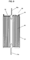
- Fig. 9 is a sectional view depicting a structure of capacitor 90 used for a capacitor device of the prior art.
- Capacitor element 30 includes aluminum foils, each having a polarizable electrode layer formed thereon, which serve as electrodes (i.e., collectors). A pair of the electrodes are arranged in positions shifted with respect to each other, with a separator placed between them, and this pair of the electrodes and the separator are wound together.
- Capacitor element 30 made in this manner is provided with a positive electrode and a negative electrode tapped individually from both end surfaces (i.e., the top and the bottom sides in the drawing of Fig. 9).
- Capacitor 90 comprises metal case 31 made of aluminum encasing capacitor element 30 together with an activating electrolyte, although not show in the figure, and negative electrode terminal 31a formed integrally on the bottom of metal case 31 for external connection.
- the end surface at the negative electrode side of capacitor element 30 is connected both mechanically and electrically to the inner base of metal case 31 by such means as laser welding.
- Capacitor 90 further comprises cover 32 made of aluminum, and positive electrode terminal 32a formed integrally with cover 32 for external connection.
- the end surface at the positive electrode side of capacitor element 30 is connected to cover 32 by such means as the laser welding. This also ensures the mechanical and electrical connection.
- a circumferential fringe of cover 32 and an opening edge of metal case 31 are crimped together with an interlayer of an insulating material placed between them, though not shown in the figure, to form crimped portion 33.
- the capacitor is sealed in this manner by the process of crimping.
- a capacitor device of the prior art contains a plurality of capacitors, each having positive electrode terminal 32a and negative electrode terminal 31a for external connections along a longitudinal axis in the center of metal case 31 (i.e., a vertical orientation in Fig. 9), which are coupled by using a connecting member called bus bar although not shown in Fig. 9.
- the capacitor device containing the plurality of coupled capacitors 90 is used as a backup power supply and the like purpose of a vehicle.
- Fuel-cell stack 51 of the fuel cell vehicle supplies a voltage of 400V, as shown in Fig. 10A.
- load "LO" includes a motor load and a motor controller load.
- a capacitor device of the present invention is provided with a plurality of capacitors, wherein each of the capacitors comprises a capacitor element having a positive electrode and a negative electrode in a confronting arrangement through a separator, and a metal case containing the capacitor element and an electrolyte.
- the plurality of capacitors comprises a plurality of first capacitors having metal cases serving as their positive electrodes, and a plurality of second capacitors having metal cases serving as their negative electrodes.
- the capacitor device is characterized by a structure that a pair of the first capacitor and the second capacitor form a capacitor unit by having their metal cases coupled with a metal plate, a plurality of capacitor units form a subunit by being connected in series or parallel, and a plurality of subunits form a main unit by being connected in series or parallel.
- the capacitor device of this invention helps ease connections necessary when coupling the plurality of capacitor units, and it also reduces a space required for the connections. In addition, it can reduce an undesirable resistance associated with the connections.
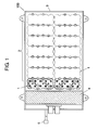
- Fig. 1 is a plan view depicting a structure of a capacitor device according to the first exemplary embodiment of the present invention
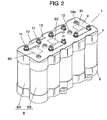
- Fig. 2 is a perspective view depicting a structure of subunit 1 used in the capacitor device.
- capacitor device 100 comprises subunit 1 having a mutually connected plurality of capacitor units 6, each of which comprises two pieces of serially connected and coupled capacitors having opposite polar orientations to each other (i.e., a first capacitor and a second capacitor).
- a plurality of subunits 1 are connected to compose main unit 2.
- Main unit 2 is then stored inside case 3.
- Case 3 contains controller 4 for controlling main unit 2, and input-output connector 5.
- Subunit 1 has five sets of coupled capacitor units 6, as shown in Fig. 2.
- Each of capacitor units 6 comprises first capacitor 6A and second capacitor 6B, which are so constructed as to be opposite in their polar orientations with respect to each other.
- the two capacitors 6A and 6B are coupled so that they are connected in series.
- description is provided of a model case, in which first capacitor 6A uses a metal case as a negative electrode, and second capacitor 6B uses a metal case as a positive electrode.
- first capacitor 6A and second capacitor 6B may be reversed of their polarities.
- Subunit 1 is held in position between upper holder 7 and lower holder 8, both made of an insulation material, and circuit board 9 is disposed on top of upper holder 7.
- Terminals 16a of capacitor units 6 project from the surface of circuit board 9, and the projecting terminals 16a located next to each other are electrically connected through bus bars 10 and mechanically secured with screws 11.
- prop 12 made of an aluminum bar, which is provided between upper holder 7 and lower holder 8 in order to prevent a vertical force impressed on capacitor device 100 from affecting directly to capacitor units 6.
- Circuit board 9 is provided on its back surface with balancing charge circuit 91 for adjusting voltages being charged equally in the plurality of capacitors that constitute subunit 1, over-voltage detecting circuit 92 for detecting an over-voltage during a charging state, and thermometric circuit 93 for monitoring a temperature around the capacitors.
- Capacitor device 100 also comprises connector 13 for connecting the individual circuits to controller 4, which controls main unit 2. Shapes and locations of the individual circuits 91, 92 and 93, and connector 13 are illustrated here as a typical example.
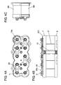
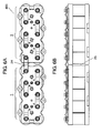
- Fig. 3A and Fig. 3B are a sectional view and a bottom view depicting a structure of capacitor unit 6.
- Capacitor unit 6 has first capacitor 6A and second capacitor 6B, as shown in Fig. 3A and Fig. 3B.
- First capacitor 6A and second capacitor 6B are so constructed that their positive and negative polarities are arranged differently with respect to each other. Description is provided here of first capacitor 6A.
- First capacitor 6A has capacitor element 14, which is provided with hollow space 14a formed therein.
- Fig. 8 is a sectional view which schematically illustrates a structure of capacitor element 14.
- Capacitor element 14 has a first electrode and a second electrode. One of the first electrode and the second electrode is a positive electrode, and the other is a negative electrode.
- the positive electrode i.e., the first electrode
- the negative electrode i.e., the second electrode
- the positive electrode is represented by first aluminum foil (collector) 141 having polarizable electrode layer 142 formed thereon
- the negative electrode i.e., the second electrode
- second aluminum foil (collector) 145 having polarizable electrode layer 144 formed thereon.
- First aluminum foil 141 and second aluminum foil 145 are wound together into such a configuration that their polarizable electrode layers 142 and 144 face each other through separator 143 with their positions shifted in opposite directions with respect to each other.
- the positive electrode and the negative electrode are tapped individually from both end surfaces of this capacitor element 14 (i.e., the top and the bottom sides in the figure).
- capacitor element 14 is encased together with an activating electrolyte, although not show in the figure, inside metal case 15 made of aluminum having a cylindrical shape with a closed bottom.
- Capacitor element 14 has protrusion 15a formed unitary with metal case 15 in an inner bottom surface thereof. This protrusion 15a is inserted into hollow space 14a of capacitor element 14.
- First capacitor 6A is completed when the end surface at the negative electrode side of capacitor element 14 inserted in metal case 15 is connected both mechanically and electrically to the inner bottom surface of metal case 15 by such means as laser welding.
- first capacitor 6A is provided with terminal plate 16 made of aluminum, which is connected to the end surface at the positive electrode side of capacitor element 14, and placed on metal case 15 to seal an opening of metal case 15.
- This terminal plate 16 has terminal 16a disposed on its surface (i.e., upper side in the figure) for external connection.
- Terminal plate 16 also has protrusion 16b unitary formed on the underside thereof (i.e., lower side in the figure), which is inserted into hollow space 14a of capacitor element 14.
- Terminal plate 16 is placed in a manner to cover the opening of metal case 15 with insulator 17 set therebetween.
- first capacitor 6A constructed as above the positive electrode of capacitor element 14 is tapped through terminal 16a provided on terminal plate 16, and the negative electrode is tapped through metal case 15.
- second capacitor 6B is so constructed that the polarities are in reverse of first capacitor 6A.
- the positive electrode of capacitor element 14 is tapped through metal case 15 and the negative electrode is tapped through terminal 16a.
- Metal plate 19 is provided to bridge between the bottom exterior surface of metal case 15 of first capacitor 6A and the bottom exterior surface of metal case 15 of second capacitor 6B, and coupled to metal cases 15 by laser welding.
- First capacitor 6A and second capacitor 6B are linked- to each other in this manner to form a pair of (or a combination of two) capacitors, as they are connected both mechanically and electrically.
- capacitor unit 6 thus constructed has one each of first capacitor 6A and second capacitor 6B connected in series.
- a material such as aluminum is especially suitable for metal plate 19 used for the connection.
- This metal plate 19 is formed in generally a hexagonal shape of such a size so that an area of metal plate 19 that comes in contact with the bottom exterior surface of each metal case 15 becomes less than 50% of the entire area of the bottom exterior surface of metal case 15. In this way, metal plate 19 ensures a sufficient coupling strength while also minimizing an adverse effect of a swelling phenomenon of the bottom of metal case 15, even if occurs due to excessive built-up of a pressure inside of metal case 15 under any abnormal condition.
- metal plate 19 formed into generally the hexagonal shape allows use of a staggered pattern when cutting a material into numbers of metal plates 19, and it thereby reduces a loss of the material substantially.
- Fig. 3B shows weld traces 19a made by laser welding when metal plate 19 is coupled to metal cases 15. The welding is so made that these weld traces 19a form linear patterns. This can reduce to the minimum extent possible an influence of distortion resulting from contraction of metal cases 15 when they return to the normal temperature after expansion by the heat of welding.
- trifoliate groove 15b shown in Fig. 3B indicates a welding rib provided for coupling one of the end surfaces of capacitor element 14 to the inner bottom of metal case 15 by laser welding.
- metal plate 19 has a thickness as thin as practicable within a range that can carry an allowable value of electric current for first capacitor 6A and second capacitor 6B without causing any failure, and also ensure a required strength as a connecting plate as well as a strength of the welding. It is desirable that the thickness is in a range of 0.1 to 0.8mm, to be specific, and a range of 0.2 to 0.5mm is even more desirable.
- capacitor device 100 of this exemplary embodiment comprises the capacitors so constructed that the electrodes of capacitor elements 14 are tapped at one side through their metal cases 15, and the electrodes of the other side are tapped through terminals 16a provided on terminal plates 16 for external connections.
- a pair of the capacitors are so constructed that their polar orientations are opposite to each other, and they are connected electrically and mechanically with metal plate 19 to configure capacitor unit 6.
- a plurality of capacitor units 6 are connected to compose subunit 1, and a plurality of subunits 1 are further connected to compose main unit 2.
- Capacitor device 100 comprises case 3, which encloses main unit 2 and controller 4 for controlling this main unit 2.
- Capacitor device 100 of this exemplary embodiment helps ease the work of connections between the capacitors, and it makes down-sizing and low-profiling possible since it substantially reduces a space required for the connections. In addition, it can reduce an undesirable resistance associated with the connections. Furthermore, since the invention makes the plurality of units separately controllable, it can provide the capacitor device of a superior performance.
- a capacitor device of the second exemplary embodiment has subunit 201, a structure of which differs partly from that of capacitor device 100 described in the first exemplary embodiment. Since the structure other than the above is analogous to that of the first exemplary embodiment, like reference marks are used to designate like components, and description will be provided of only the different portions, with reference to the accompanying drawings while details of the like components are skipped.
- Fig. 4A to 4C are a plan view, a front view and a side view depicting the structure of subunit 201 of the capacitor device according to the second exemplary embodiment of the present invention.
- Subunit 201 comprises bus bars 20, each electrically connecting adjoining terminals 16a of capacitor units 6, and bent portion 20a provided in each bus bar 20 by bending a portion thereof.
- Bent portion 20a provided in subunit 201 functions as a buffer to absorb dimensional variations even when such variations exist in height of capacitor units 6 consisting of first capacitors 6A and second capacitors 6B.
- the structure can thus achieve the capacitor device capable of maintaining a high dimensional precision.
- Spaces 21 provided individually among the plurality of capacitor units that compose subunit 201. Spaces 21 provided in this manner can promote dissipation of the heat produced by first capacitors 6A and second capacitors to the outside, thereby achieving the capacitor device of a superior heat-radiating characteristic.
- a capacitor device of the third exemplary embodiment has one of subunits 301 and 302, structures of which differ partly from that of capacitor device 100 described in the first exemplary embodiment. Since the structures other than the above are analogous to that of the first exemplary embodiment, like reference marks are used to designate like components, and description will be provided of only the different portions with reference to the accompanying drawings while details of the like components are skipped.
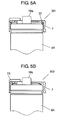
- Fig. 5A is a sectional view depicting a main part of the structure of subunit 301 of the capacitor device according to the third exemplary embodiment of the present invention.
- Subunit 301 has first capacitor 6A, upper holder 7 and terminal 16a.
- O-ring 22 made of rubber placed between a peripheral edge on an upper surface of first capacitor 6A and an inner surface of upper holder 7. This O-ring 22 is provided for the purpose of functioning it as a buffer to absorb variations in height of the individual capacitors that compose subunit 301. Even if the individual capacitors have such variations in their height within a tolerable range, O-ring 22 can absorb the dimensional variations, and it thereby maintains a high dimensional precision of subunit 301.
- plate spring 23 made of a spring material such as phosphor bronze, as shown in subunit 302 of Fig. 5B, in order to make it function as the buffer to absorb the variations in the height of the individual capacitors.
- the capacitor device comprises any of O-ring 22 and plate spring 23 having the function of buffer, which is disposed between the peripheral edge on the upper surface of first capacitor 6A and the inner surface of upper holder 7, to absorb the variations in the height of the individual capacitors that form one of subunits 301 and 302.
- buffer which is disposed between the peripheral edge on the upper surface of first capacitor 6A and the inner surface of upper holder 7, to absorb the variations in the height of the individual capacitors that form one of subunits 301 and 302.
- Capacitor device 400 disclosed in the fourth exemplary embodiment has a main unit, a structure of which differs partly from that of capacitor device 100 described in the first exemplary embodiment. Since the structure other than the above is analogous to that of the first exemplary embodiment, like reference marks are used to designate like components, and description will be provided of only the different portions with reference to the accompanying drawings while details of the like components are skipped.
- Fig. 6A and 6B are a plan view and a front view depicting a main part of the structure of the main unit of capacitor device 400 according to the fourth exemplary embodiment of the present invention.
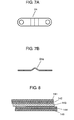
- Fig. 7A and 7B are a plan view and a front view depicting connecting plate 24 used for the main unit.
- Capacitor device 400 has connecting plate 24 connecting terminals of adjoining subunits 1, and bent portion 24a provided in connecting plate 24 by bending a portion thereof.
- this bent portion 24a plays the role of buffer to absorb dimensional variations even when they exist in the height of the adjoining subunits 1.
- the structure can achieve the capacitor device capable of maintaining a high dimensional precision.
- Spaces 25 provided individually among the plurality of subunits 1 that compose the main unit. Spaces 25 provided in this manner can promote dissipation of the heat produced by subunits 1 to the outside, thereby achieving the capacitor device of a superior heat-radiating characteristic.
- a capacitor device of the present invention helps facilitate connections between capacitors.
- the invention substantially reduces a space required for the connections, decreases an undesirable resistance associated with the connections, makes a plurality of units separately controllable, and thereby it has an advantage of realizing the capacitor device of small size and high performance, which is suitable for use in a regeneration system of a hybrid car, fuel cell vehicle, and the like.
Landscapes
- Engineering & Computer Science (AREA)
- Power Engineering (AREA)
- Microelectronics & Electronic Packaging (AREA)
- Electric Double-Layer Capacitors Or The Like (AREA)
- Fixed Capacitors And Capacitor Manufacturing Machines (AREA)
Abstract
A capacitor device has a plurality of capacitors, each comprising a capacitor element having a positive electrode and a negative electrode in a confronting arrangement through a separator, and a metal case encasing the capacitor element and an electrolyte. The plurality of capacitors comprise a plurality of first capacitors, each using the metal case as a negative electrode, and a plurality of second capacitors, each using the metal case as a positive electrode. The capacitor device is characterized by a structure that a pair of the first capacitor and the second capacitor form a capacitor unit by having their metal cases coupled with a metal plate, a plurality of capacitor units form a subunit by being connected in series or parallel, and a plurality of subunits form a main unit by being connected in series or parallel. The invention helps facilitate connections when coupling the plurality of capacitor units, and substantially reduces a space required for the connections. The invention also decreases an undesirable resistance associated with the connections.
Description
- The present invention relates to a capacitor device used for the purpose of regeneration or storage of power in a hybrid car, fuel cell vehicle, and the like.
- Fig. 9 is a sectional view depicting a structure of
capacitor 90 used for a capacitor device of the prior art.Capacitor element 30 includes aluminum foils, each having a polarizable electrode layer formed thereon, which serve as electrodes (i.e., collectors). A pair of the electrodes are arranged in positions shifted with respect to each other, with a separator placed between them, and this pair of the electrodes and the separator are wound together.Capacitor element 30 made in this manner is provided with a positive electrode and a negative electrode tapped individually from both end surfaces (i.e., the top and the bottom sides in the drawing of Fig. 9). -
Capacitor 90 comprisesmetal case 31 made of aluminum encasingcapacitor element 30 together with an activating electrolyte, although not show in the figure, andnegative electrode terminal 31a formed integrally on the bottom ofmetal case 31 for external connection. The end surface at the negative electrode side ofcapacitor element 30 is connected both mechanically and electrically to the inner base ofmetal case 31 by such means as laser welding. -
Capacitor 90 further comprisescover 32 made of aluminum, andpositive electrode terminal 32a formed integrally withcover 32 for external connection. The end surface at the positive electrode side ofcapacitor element 30 is connected to cover 32 by such means as the laser welding. This also ensures the mechanical and electrical connection. At the same time, a circumferential fringe ofcover 32 and an opening edge ofmetal case 31 are crimped together with an interlayer of an insulating material placed between them, though not shown in the figure, to form crimpedportion 33. The capacitor is sealed in this manner by the process of crimping. - A capacitor device of the prior art contains a plurality of capacitors, each having
positive electrode terminal 32a andnegative electrode terminal 31a for external connections along a longitudinal axis in the center of metal case 31 (i.e., a vertical orientation in Fig. 9), which are coupled by using a connecting member called bus bar although not shown in Fig. 9. The capacitor device containing the plurality of coupledcapacitors 90 is used as a backup power supply and the like purpose of a vehicle. - One example of the above prior art is disclosed in
Japanese Patent Unexamined Publication, No. 2000-315632 - In the capacitor device of the prior art, however, it has not been so easy to make connections of
positive electrode terminals 32a andnegative electrode terminals 31a in the process of coupling the plurality ofcapacitors 90 since these terminals are pulled out to the opposite sides with respect to each other. This device has also had a problem that it cannot be reduced in size because it requires connecting spaces at both sides, which inevitably results in a large mounting space in all. - Moreover, when the above conventional capacitor device having a plurality of coupled
capacitors 90 is used as an auxiliary power supply for a motor of a fuel cell vehicle, it necessitates lengthy routing of connecting lines for the reason that the terminals are located at both ends opposite to each other. Consequently, there has been a problem that a large loss occurs due to an undesirable increase in resistance. - Description is now provided about this undesirable increase in resistance by using an example of a fuel-cell stack for a fuel cell vehicle, with reference to Fig. 10A and 10B.
- Fuel-
cell stack 51 of the fuel cell vehicle supplies a voltage of 400V, as shown in Fig. 10A. On the other hand,capacitors 60 of capacitance "Ci" have a rated voltage of approx. 2.0V. It is therefore necessary to provide 200 units of capacitors (i.e., 400V/2V = 200) connected in series. A load current of approx. 200A flows at the maximum. Here, load "LO" includes a motor load and a motor controller load. - Each of the capacitors has an internal resistance "R1" of 0.002Ω, as shown in Fig. 10B. Assume that there is connection resistance "R2" of 0.0001Ω at terminals of the individual capacitors, it is added up to 0.0021Ω (i.e., 0.002+0.0001 = 0.0021) when connected in series. A total resistance thus becomes 0.0021Ω×200 = 0.42Ω in the case of the 200 units of serially connected capacitors.
- When the current of 200A flows through the combined resistance of 0.42Ω, it generates 16.8kW of heat (i.e., 0.42Ω×200A×200A = 16.8kW) as a loss of the capacitors, which is dissipated outside.
- In the case of the conventional capacitor device, there has been the problem as described above, that a substantial amount of heat is dissipated due to the large loss generated by the resistance attributed to the connections.
- A capacitor device of the present invention is provided with a plurality of capacitors, wherein each of the capacitors comprises a capacitor element having a positive electrode and a negative electrode in a confronting arrangement through a separator, and a metal case containing the capacitor element and an electrolyte. The plurality of capacitors comprises a plurality of first capacitors having metal cases serving as their positive electrodes, and a plurality of second capacitors having metal cases serving as their negative electrodes. The capacitor device is characterized by a structure that a pair of the first capacitor and the second capacitor form a capacitor unit by having their metal cases coupled with a metal plate, a plurality of capacitor units form a subunit by being connected in series or parallel, and a plurality of subunits form a main unit by being connected in series or parallel.
- The capacitor device of this invention helps ease connections necessary when coupling the plurality of capacitor units, and it also reduces a space required for the connections. In addition, it can reduce an undesirable resistance associated with the connections.
-
- Fig. 1 is a plan view depicting a structure of a capacitor device according to a first exemplary embodiment of the present invention;
- Fig. 2 is a perspective view depicting a structure of a subunit used in the capacitor device according to the first exemplary embodiment of the present invention;
- Fig. 3A is a sectional view depicting a structure of a capacitor unit used in the capacitor device according to the first exemplary embodiment of the present invention;
- Fig. 3B is a bottom view depicting the structure of the capacitor unit used in the capacitor device according to the first exemplary embodiment of the present invention;
- Fig. 4A is a plan view depicting a structure of a subunit of a capacitor device according to a second exemplary embodiment of the present invention;
- Fig. 4B is a front view depicting the structure of the subunit of the capacitor device according to the second exemplary embodiment of the present invention;
- Fig. 4C is a side view depicting the structure of the subunit of the capacitor device according to the second exemplary embodiment of the present invention;
- Fig. 5A is a sectional view depicting a main part of a structure of a subunit of a capacitor device according to a third exemplary embodiment of the present invention;
- Fig. 5B is a sectional view depicting a main part of another structure of the subunit of the capacitor device according to the third exemplary embodiment of the present invention;
- Fig. 6A is a plan view depicting a main part of a structure of a main unit of a capacitor device according to a fourth exemplary embodiment of the present invention;
- Fig. 6B is a front view depicting the main part of the structure of the main unit of the capacitor device according to the fourth exemplary embodiment of the present invention;
- Fig. 7A is a plan view depicting a connecting plate used for the main unit of the capacitor device according to the fourth exemplary embodiment of the present invention;
- Fig. 7B is a front view depicting the connecting plate used for the main unit of the capacitor device according to the fourth exemplary embodiment of the present invention;
- Fig. 8 is a sectional view depicting a partial structure of the capacitor element according to the present invention;
- Fig. 9 is a sectional view depicting a structure of a capacitor used in a capacitor device of the prior art;
- Fig. 10A is a conceptual diagram showing a theory of emerging an undesirable resistance when connecting a plurality of capacitor units of the prior art ; and
- Fig. 10B is another conceptual diagram showing the theory of emerging the undesirable resistance when connecting the plurality of capacitor units of the prior art.
-
- 1
- subunit
- 2
- main unit
- 3
- case
- 4
- controller
- 5
- input-output connector
- 6
- capacitor unit
- 6A
- first capacitor
- 6B
- second capacitor
- 7
- upper holder
- 8
- lower holder
- 9
- circuit board
- 10, 20
- bus bar
- 11
- screw
- 12
- prop
- 13
- connector
- 14
- capacitor element
- 14a
- hollow space
- 15
- metal case
- 15a, 16b
- protrusion
- 16
- terminal plate
- 16a
- terminal
- 17
- insulator
- 18
- sealing rubber
- 19
- metal plate
- 19a
- weld trace
- 24
- connecting plate
- 20a, 24a
- bent portion
- 21, 25
- space
- 22
- O-ring (buffer)
- 23
- plate spring (buffer)
- Description is provided concretely of one mode of the present invention by using the first exemplary embodiment below.
- Fig. 1 is a plan view depicting a structure of a capacitor device according to the first exemplary embodiment of the present invention, and Fig. 2 is a perspective view depicting a structure of
subunit 1 used in the capacitor device. - As shown in Fig. 1 and Fig. 2,
capacitor device 100 comprisessubunit 1 having a mutually connected plurality ofcapacitor units 6, each of which comprises two pieces of serially connected and coupled capacitors having opposite polar orientations to each other (i.e., a first capacitor and a second capacitor). A plurality ofsubunits 1 are connected to composemain unit 2.Main unit 2 is then stored insidecase 3.Case 3 contains controller 4 for controllingmain unit 2, and input-output connector 5. -
Subunit 1 has five sets of coupledcapacitor units 6, as shown in Fig. 2. Each ofcapacitor units 6 comprisesfirst capacitor 6A andsecond capacitor 6B, which are so constructed as to be opposite in their polar orientations with respect to each other. The twocapacitors first capacitor 6A uses a metal case as a negative electrode, andsecond capacitor 6B uses a metal case as a positive electrode. However,first capacitor 6A andsecond capacitor 6B may be reversed of their polarities. -
Subunit 1 is held in position betweenupper holder 7 andlower holder 8, both made of an insulation material, andcircuit board 9 is disposed on top ofupper holder 7.Terminals 16a ofcapacitor units 6 project from the surface ofcircuit board 9, and the projectingterminals 16a located next to each other are electrically connected throughbus bars 10 and mechanically secured withscrews 11. - There is also prop 12 made of an aluminum bar, which is provided between
upper holder 7 andlower holder 8 in order to prevent a vertical force impressed oncapacitor device 100 from affecting directly tocapacitor units 6. -
Circuit board 9 is provided on its back surface with balancingcharge circuit 91 for adjusting voltages being charged equally in the plurality of capacitors that constitutesubunit 1, over-voltage detectingcircuit 92 for detecting an over-voltage during a charging state, andthermometric circuit 93 for monitoring a temperature around the capacitors.Capacitor device 100 also comprisesconnector 13 for connecting the individual circuits to controller 4, which controlsmain unit 2. Shapes and locations of theindividual circuits connector 13 are illustrated here as a typical example. - Fig. 3A and Fig. 3B are a sectional view and a bottom view depicting a structure of
capacitor unit 6.Capacitor unit 6 hasfirst capacitor 6A andsecond capacitor 6B, as shown in Fig. 3A and Fig. 3B.First capacitor 6A andsecond capacitor 6B are so constructed that their positive and negative polarities are arranged differently with respect to each other. Description is provided here offirst capacitor 6A. -
First capacitor 6A hascapacitor element 14, which is provided withhollow space 14a formed therein. - With reference to Fig. 8, description is provided hereafter of
capacitor element 14. Fig. 8 is a sectional view which schematically illustrates a structure ofcapacitor element 14.Capacitor element 14 has a first electrode and a second electrode. One of the first electrode and the second electrode is a positive electrode, and the other is a negative electrode. In the example of Fig. 8, the positive electrode (i.e., the first electrode) is represented by first aluminum foil (collector) 141 havingpolarizable electrode layer 142 formed thereon, and the negative electrode (i.e., the second electrode) is represented by second aluminum foil (collector) 145 havingpolarizable electrode layer 144 formed thereon.First aluminum foil 141 andsecond aluminum foil 145 are wound together into such a configuration that their polarizable electrode layers 142 and 144 face each other throughseparator 143 with their positions shifted in opposite directions with respect to each other. The positive electrode and the negative electrode are tapped individually from both end surfaces of this capacitor element 14 (i.e., the top and the bottom sides in the figure). - As shown in Fig. 3A,
capacitor element 14 is encased together with an activating electrolyte, although not show in the figure, insidemetal case 15 made of aluminum having a cylindrical shape with a closed bottom.Capacitor element 14 hasprotrusion 15a formed unitary withmetal case 15 in an inner bottom surface thereof. Thisprotrusion 15a is inserted intohollow space 14a ofcapacitor element 14.First capacitor 6A is completed when the end surface at the negative electrode side ofcapacitor element 14 inserted inmetal case 15 is connected both mechanically and electrically to the inner bottom surface ofmetal case 15 by such means as laser welding. - In addition,
first capacitor 6A is provided withterminal plate 16 made of aluminum, which is connected to the end surface at the positive electrode side ofcapacitor element 14, and placed onmetal case 15 to seal an opening ofmetal case 15. Thisterminal plate 16 has terminal 16a disposed on its surface (i.e., upper side in the figure) for external connection.Terminal plate 16 also hasprotrusion 16b unitary formed on the underside thereof (i.e., lower side in the figure), which is inserted intohollow space 14a ofcapacitor element 14.Terminal plate 16 is placed in a manner to cover the opening ofmetal case 15 withinsulator 17 set therebetween. There is sealingrubber 18 placed around a peripheral edge of the front side ofterminal plate 16, and the open end ofmetal case 15 is crimped in a manner to compress this sealingrubber 18 to sealmetal case 15. - In
first capacitor 6A constructed as above, the positive electrode ofcapacitor element 14 is tapped throughterminal 16a provided onterminal plate 16, and the negative electrode is tapped throughmetal case 15. On the other hand,second capacitor 6B is so constructed that the polarities are in reverse offirst capacitor 6A. In other words, the positive electrode ofcapacitor element 14 is tapped throughmetal case 15 and the negative electrode is tapped throughterminal 16a. -
Metal plate 19 is provided to bridge between the bottom exterior surface ofmetal case 15 offirst capacitor 6A and the bottom exterior surface ofmetal case 15 ofsecond capacitor 6B, and coupled tometal cases 15 by laser welding.First capacitor 6A andsecond capacitor 6B are linked- to each other in this manner to form a pair of (or a combination of two) capacitors, as they are connected both mechanically and electrically. In other words,capacitor unit 6 thus constructed has one each offirst capacitor 6A andsecond capacitor 6B connected in series. A material such as aluminum is especially suitable formetal plate 19 used for the connection. - This
metal plate 19 is formed in generally a hexagonal shape of such a size so that an area ofmetal plate 19 that comes in contact with the bottom exterior surface of eachmetal case 15 becomes less than 50% of the entire area of the bottom exterior surface ofmetal case 15. In this way,metal plate 19 ensures a sufficient coupling strength while also minimizing an adverse effect of a swelling phenomenon of the bottom ofmetal case 15, even if occurs due to excessive built-up of a pressure inside ofmetal case 15 under any abnormal condition. In addition,metal plate 19 formed into generally the hexagonal shape allows use of a staggered pattern when cutting a material into numbers ofmetal plates 19, and it thereby reduces a loss of the material substantially. - Fig. 3B shows weld traces 19a made by laser welding when
metal plate 19 is coupled tometal cases 15. The welding is so made that these weld traces 19a form linear patterns. This can reduce to the minimum extent possible an influence of distortion resulting from contraction ofmetal cases 15 when they return to the normal temperature after expansion by the heat of welding. Here,trifoliate groove 15b shown in Fig. 3B indicates a welding rib provided for coupling one of the end surfaces ofcapacitor element 14 to the inner bottom ofmetal case 15 by laser welding. - It is desirable that
metal plate 19 has a thickness as thin as practicable within a range that can carry an allowable value of electric current forfirst capacitor 6A andsecond capacitor 6B without causing any failure, and also ensure a required strength as a connecting plate as well as a strength of the welding. It is desirable that the thickness is in a range of 0.1 to 0.8mm, to be specific, and a range of 0.2 to 0.5mm is even more desirable. - As described above,
capacitor device 100 of this exemplary embodiment comprises the capacitors so constructed that the electrodes ofcapacitor elements 14 are tapped at one side through theirmetal cases 15, and the electrodes of the other side are tapped throughterminals 16a provided onterminal plates 16 for external connections. A pair of the capacitors are so constructed that their polar orientations are opposite to each other, and they are connected electrically and mechanically withmetal plate 19 to configurecapacitor unit 6. A plurality ofcapacitor units 6 are connected to composesubunit 1, and a plurality ofsubunits 1 are further connected to composemain unit 2.Capacitor device 100 comprisescase 3, which enclosesmain unit 2 and controller 4 for controlling thismain unit 2.Capacitor device 100 of this exemplary embodiment helps ease the work of connections between the capacitors, and it makes down-sizing and low-profiling possible since it substantially reduces a space required for the connections. In addition, it can reduce an undesirable resistance associated with the connections. Furthermore, since the invention makes the plurality of units separately controllable, it can provide the capacitor device of a superior performance. - Description is provided hereinafter of another mode of the present invention by using the second exemplary embodiment.
- A capacitor device of the second exemplary embodiment has
subunit 201, a structure of which differs partly from that ofcapacitor device 100 described in the first exemplary embodiment. Since the structure other than the above is analogous to that of the first exemplary embodiment, like reference marks are used to designate like components, and description will be provided of only the different portions, with reference to the accompanying drawings while details of the like components are skipped. - Fig. 4A to 4C are a plan view, a front view and a side view depicting the structure of
subunit 201 of the capacitor device according to the second exemplary embodiment of the present invention.Subunit 201 comprises bus bars 20, each electrically connecting adjoiningterminals 16a ofcapacitor units 6, andbent portion 20a provided in eachbus bar 20 by bending a portion thereof. -
Bent portion 20a provided insubunit 201 functions as a buffer to absorb dimensional variations even when such variations exist in height ofcapacitor units 6 consisting offirst capacitors 6A andsecond capacitors 6B. The structure can thus achieve the capacitor device capable of maintaining a high dimensional precision. - In addition, there are
spaces 21 provided individually among the plurality of capacitor units that composesubunit 201.Spaces 21 provided in this manner can promote dissipation of the heat produced byfirst capacitors 6A and second capacitors to the outside, thereby achieving the capacitor device of a superior heat-radiating characteristic. - Description is provided hereinafter of still another mode of the present invention by using the third exemplary embodiment.
- A capacitor device of the third exemplary embodiment has one of
subunits capacitor device 100 described in the first exemplary embodiment. Since the structures other than the above are analogous to that of the first exemplary embodiment, like reference marks are used to designate like components, and description will be provided of only the different portions with reference to the accompanying drawings while details of the like components are skipped. - Fig. 5A is a sectional view depicting a main part of the structure of
subunit 301 of the capacitor device according to the third exemplary embodiment of the present invention.Subunit 301 hasfirst capacitor 6A,upper holder 7 and terminal 16a. - There is O-
ring 22 made of rubber placed between a peripheral edge on an upper surface offirst capacitor 6A and an inner surface ofupper holder 7. This O-ring 22 is provided for the purpose of functioning it as a buffer to absorb variations in height of the individual capacitors that composesubunit 301. Even if the individual capacitors have such variations in their height within a tolerable range, O-ring 22 can absorb the dimensional variations, and it thereby maintains a high dimensional precision ofsubunit 301. - It is also suitable to use
plate spring 23 made of a spring material such as phosphor bronze, as shown insubunit 302 of Fig. 5B, in order to make it function as the buffer to absorb the variations in the height of the individual capacitors. - It is thus possible, in the case of
subunit 302, to makeplate spring 23 absorb the dimensional variations within a tolerable range, even if such variations exist in the height of the individual capacitors, thereby maintaining a high dimensional precision of the subunit. - As described above, the capacitor device according to the third exemplary embodiment comprises any of O-
ring 22 andplate spring 23 having the function of buffer, which is disposed between the peripheral edge on the upper surface offirst capacitor 6A and the inner surface ofupper holder 7, to absorb the variations in the height of the individual capacitors that form one ofsubunits subunits - In this third exemplary embodiment, although the description is provided of the example that either one of O-
ring 22 andplate spring 23 having the function of buffer is disposed between the peripheral edge on the upper surface of the capacitor and the inner surface ofupper holder 7, the present invention is not to be considered as restrictive, but it may be so embodied that the buffer be disposed between a bottom surface ofcapacitor 6A (or 6B) and an inner surface oflower holder 8. - Description is provided hereinafter of yet another mode of the present invention by using the fourth exemplary embodiment.
-
Capacitor device 400 disclosed in the fourth exemplary embodiment has a main unit, a structure of which differs partly from that ofcapacitor device 100 described in the first exemplary embodiment. Since the structure other than the above is analogous to that of the first exemplary embodiment, like reference marks are used to designate like components, and description will be provided of only the different portions with reference to the accompanying drawings while details of the like components are skipped. - Fig. 6A and 6B are a plan view and a front view depicting a main part of the structure of the main unit of
capacitor device 400 according to the fourth exemplary embodiment of the present invention. Fig. 7A and 7B are a plan view and a front view depicting connectingplate 24 used for the main unit.Capacitor device 400 has connectingplate 24 connecting terminals of adjoiningsubunits 1, andbent portion 24a provided in connectingplate 24 by bending a portion thereof. - Owing to the structure, in which connecting
plate 24 havingbent portion 24a is used for connecting between the terminals of adjoiningsubunits 1, thisbent portion 24a plays the role of buffer to absorb dimensional variations even when they exist in the height of the adjoiningsubunits 1. As a result, the structure can achieve the capacitor device capable of maintaining a high dimensional precision. - In addition, there are
spaces 25 provided individually among the plurality ofsubunits 1 that compose the main unit.Spaces 25 provided in this manner can promote dissipation of the heat produced bysubunits 1 to the outside, thereby achieving the capacitor device of a superior heat-radiating characteristic. - A capacitor device of the present invention helps facilitate connections between capacitors. The invention substantially reduces a space required for the connections, decreases an undesirable resistance associated with the connections, makes a plurality of units separately controllable, and thereby it has an advantage of realizing the capacitor device of small size and high performance, which is suitable for use in a regeneration system of a hybrid car, fuel cell vehicle, and the like.
Claims (11)
- A capacitor device containing a plurality of capacitors,
each of the capacitors comprising a capacitor element having a positive electrode and a negative electrode in a confronting arrangement through a separator, and a metal case containing the capacitor element and an electrolyte,
the plurality of capacitors comprising a plurality of first capacitors, each using the metal case as a negative electrode thereof, and a plurality of second capacitors, each using the metal case as a positive electrode thereof,
wherein each of the first capacitors and each of the second capacitors form a capacitor unit with their metal cases coupled together through a metal plate,
a plurality of capacitor units are connected in any of series and parallel to form a subunit, and
a plurality of subunits are connected in any of series and parallel to form a main unit of the capacitor device. - The capacitor device as set forth in claim 1 further comprising terminal plates, each covering an opening of the metal case, wherein
each of the terminal plates has a terminal connected to one of the positive electrode and the negative electrode, and
the terminal connected to the positive electrode of one of the capacitor units and another terminal connected to the negative electrode of the adjoining capacitor unit are connected with a bus bar. - A capacitor device containing a plurality of capacitors,
each of the capacitors comprising a capacitor element, a metal case and a terminal plate,
the capacitor element comprising a first electrode, a second electrode and a separator, wherein each of the first electrode and the second electrode is made of a metal foil having a polarizable electrode layer formed thereon, the first electrode and the second electrode are wound into a configuration that the polarizable electrode layer of the first electrode and the polarizable electrode layer of the second electrode face each other through the separator with the first electrode and the second electrode shifted beyond sides of the separator in opposite directions with respect to each other,
the metal case containing the capacitor element and an electrolyte in a manner that the first electrode is coupled to a bottom surface of the metal case,
the terminal plate covering an opening of the metal case, the second electrode coupled to a terminal provided on the terminal plate,
wherein
the plurality of capacitors are coupled to form capacitor units, each including a pair of the capacitors having the first electrodes of opposite polarities with respect to each other and the metal cases of the pair of the capacitors are coupled together,
a plurality of the capacitor units are connected in any of series and parallel to form subunits,
a plurality of the subunits are connected in any of series and parallel to form a main unit, and
the capacitor device further comprises a case containing the main unit and a controller for controlling the main unit. - The capacitor device as set forth in claim 3 further comprising a metal plate coupling together the metal cases of the pair of the capacitors.
- The capacitor device as set forth in claim 3 further comprising:a bus bar connecting together the capacitor units;an upper holder made of an insulation material holding an upper side of the subunit;a lower holder made of an insulation material holding a lower side of the subunit; anda prop retaining the upper holder and the lower holder.
- The capacitor device as set forth in claim 5, wherein the bus bar has a bent portion.
- The capacitor device as set forth in claim 5 further comprising a buffer placed between at least one of the upper holder and the lower holder and the capacitors for absorbing a variation in height of the capacitors.
- The capacitor device as set forth in claim 3, wherein the subunit has a space provided between the plurality of capacitor units.
- The capacitor device as set forth in claim 3 further comprising a connecting plate connecting together the plurality of subunits, and the connecting plate having a bent portion.
- The capacitor device as set forth in claim 3, wherein the main unit has a space provided between the plurality of subunits.
- The capacitor device as set forth in claim 3, wherein:the subunit has a circuit board;the circuit board is provided with a balancing charge circuit for adjusting charge voltages of the capacitors equally, an over-voltage detecting circuit for detecting an over-voltage during a charging state, and a thermometric circuit for monitoring a temperature around the capacitors; andthe subunit is connected to the controller.
Applications Claiming Priority (2)
| Application Number | Priority Date | Filing Date | Title |
|---|---|---|---|
| JP2005177241A JP2006351897A (en) | 2005-06-17 | 2005-06-17 | Capacitor |
| PCT/JP2006/311729 WO2006134859A1 (en) | 2005-06-17 | 2006-06-12 | Condenser device |
Publications (1)
| Publication Number | Publication Date |
|---|---|
| EP1843361A1 true EP1843361A1 (en) | 2007-10-10 |
Family
ID=37532221
Family Applications (1)
| Application Number | Title | Priority Date | Filing Date |
|---|---|---|---|
| EP06766591A Withdrawn EP1843361A1 (en) | 2005-06-17 | 2006-06-12 | Condenser device |
Country Status (4)
| Country | Link |
|---|---|
| US (1) | US7580245B2 (en) |
| EP (1) | EP1843361A1 (en) |
| JP (1) | JP2006351897A (en) |
| WO (1) | WO2006134859A1 (en) |
Cited By (8)
| Publication number | Priority date | Publication date | Assignee | Title |
|---|---|---|---|---|
| FR2990063A1 (en) * | 2012-04-30 | 2013-11-01 | Batscap Sa | DEVICE FOR MAINTAINING AN ELECTRIC ENERGY STORAGE ASSEMBLY |
| WO2014044941A1 (en) * | 2012-09-24 | 2014-03-27 | Valeo Equipements Electriques Moteur | Process for manufacturing a store of electrical energy and corresponding store |
| CN104143448A (en) * | 2014-07-04 | 2014-11-12 | 苏州腾冉电气设备有限公司 | Super-capacitor module |
| EP2520455A3 (en) * | 2011-05-02 | 2015-08-26 | STILL GmbH | Electrical energy storage device for vehicle with electric drive |
| CN105958505A (en) * | 2016-05-27 | 2016-09-21 | 国网新疆电力公司乌鲁木齐供电公司 | Graphene intelligent capacitor |
| WO2017191135A3 (en) * | 2016-05-03 | 2018-01-11 | Moog Unna Gmbh | Energy storage assembly with a resilient layer |
| CN108885945A (en) * | 2016-03-16 | 2018-11-23 | Ls美创有限公司 | Energy storage module connection structural bodies |
| EP3756203A4 (en) * | 2018-02-22 | 2021-11-17 | AVX Corporation | Encapsulated supercapacitor module having a high voltage and low equivalent series resistance |
Families Citing this family (31)
| Publication number | Priority date | Publication date | Assignee | Title |
|---|---|---|---|---|
| DE10339156B3 (en) * | 2003-08-26 | 2005-03-17 | Epcos Ag | Circuit arrangement with several capacities |
| US8110310B2 (en) * | 2007-02-07 | 2012-02-07 | Central Research Institute Of Electric Power Industry | Power generating plant |
| JP2008204985A (en) * | 2007-02-16 | 2008-09-04 | Matsushita Electric Ind Co Ltd | Capacitor unit |
| JP5162918B2 (en) * | 2007-02-16 | 2013-03-13 | パナソニック株式会社 | Capacitor unit and manufacturing method thereof |
| ATE539440T1 (en) * | 2007-02-16 | 2012-01-15 | Panasonic Corp | ELECTRICAL STORAGE UNIT |
| JP5018204B2 (en) * | 2007-04-19 | 2012-09-05 | パナソニック株式会社 | Power storage unit |
| WO2008099614A1 (en) * | 2007-02-16 | 2008-08-21 | Panasonic Corporation | Capacitor unit and its manufacturing method |
| JP5018119B2 (en) * | 2007-02-16 | 2012-09-05 | パナソニック株式会社 | Power storage unit |
| JP5162919B2 (en) * | 2007-02-16 | 2013-03-13 | パナソニック株式会社 | Power storage unit |
| JP5018203B2 (en) * | 2007-04-19 | 2012-09-05 | パナソニック株式会社 | Power storage unit |
| US8760847B2 (en) | 2010-11-30 | 2014-06-24 | Pratt & Whitney Canada Corp. | Low inductance capacitor assembly |
| US8787003B2 (en) * | 2011-10-12 | 2014-07-22 | Infineon Technologies Ag | Low inductance capacitor module and power system with low inductance capacitor module |
| JP2013115221A (en) * | 2011-11-29 | 2013-06-10 | Shin Kobe Electric Mach Co Ltd | Capacitor module |
| FR2986657B1 (en) * | 2012-02-03 | 2014-01-31 | Batscap Sa | POSITIONING SPACER, ENERGY STORAGE MODULE THE ASSEMBLY AND METHOD FOR ASSEMBLING THE MODULE |
| JP5734364B2 (en) * | 2012-11-22 | 2015-06-17 | 株式会社デンソー | Power converter |
| US9899643B2 (en) | 2013-02-27 | 2018-02-20 | Ioxus, Inc. | Energy storage device assembly |
| US9738976B2 (en) | 2013-02-27 | 2017-08-22 | Ioxus, Inc. | Energy storage device assembly |
| EP2962316B1 (en) * | 2013-02-27 | 2019-07-03 | Ioxus, Inc. | Energy storage device assembly |
| US9892868B2 (en) | 2013-06-21 | 2018-02-13 | Ioxus, Inc. | Energy storage device assembly |
| ES2535152B1 (en) | 2013-10-03 | 2015-11-24 | Caf Power & Automation, S.L.U. | POWER ACCUMULATION BASKET |
| KR102139759B1 (en) * | 2015-01-20 | 2020-07-31 | 삼성전기주식회사 | Multi-layered ceramic electroic components |
| KR102072080B1 (en) * | 2015-01-21 | 2020-01-31 | 엘에스엠트론 주식회사 | Energy storing device |
| JP6347768B2 (en) | 2015-01-22 | 2018-06-27 | カルソニックカンセイ株式会社 | Capacitor structure |
| US9916934B1 (en) * | 2016-04-11 | 2018-03-13 | Cornell Dubilier Electronics, Inc. | Multi-rated capacitor assembly |
| JP6970875B2 (en) * | 2016-05-25 | 2021-11-24 | パナソニックIpマネジメント株式会社 | Capacitor |
| EP3646358A4 (en) | 2017-06-30 | 2021-04-07 | AVX Corporation | Heat dissipation from a balancing circuit for an ultracapacitor module |
| JP7213408B2 (en) * | 2017-11-29 | 2023-01-27 | パナソニックIpマネジメント株式会社 | capacitor |
| US11043337B2 (en) | 2018-02-22 | 2021-06-22 | Avx Corporation | Meter including a supercapacitor |
| EP3756202A4 (en) | 2018-02-22 | 2021-11-17 | AVX Corporation | Electrical circuit including a supercapacitor with reduced leakage |
| KR20230093431A (en) * | 2020-10-26 | 2023-06-27 | 교세라 에이브이엑스 컴포넌츠 코포레이션 | Ultracapacitor module with improved vibration resistance |
| CN115240980A (en) * | 2021-04-16 | 2022-10-25 | 北京科益虹源光电技术有限公司 | High-strength elastic capacitor current equalizing structure and processing method |
Family Cites Families (15)
| Publication number | Priority date | Publication date | Assignee | Title |
|---|---|---|---|---|
| JPS5895629A (en) | 1981-11-28 | 1983-06-07 | Nippon Valqua Ind Ltd | Making glass and glass fiber hydrophilic |
| JPS5895629U (en) * | 1981-12-22 | 1983-06-29 | 松下電器産業株式会社 | electric double layer capacitor |
| JPH0325223A (en) | 1989-06-23 | 1991-02-04 | Matsushita Electric Ind Co Ltd | High frequency heating device |
| JPH073629Y2 (en) * | 1989-07-24 | 1995-01-30 | 株式会社指月電機製作所 | Capacitor element block |
| JPH09148183A (en) * | 1995-11-22 | 1997-06-06 | Toshiba Corp | Capacitor unit |
| JP3652027B2 (en) * | 1996-10-02 | 2005-05-25 | 本田技研工業株式会社 | Storage capacitor structure |
| JP2000315632A (en) | 1999-03-02 | 2000-11-14 | Matsushita Electric Ind Co Ltd | Capacitor |
| JP3681051B2 (en) * | 1999-12-28 | 2005-08-10 | 本田技研工業株式会社 | Power storage device |
| JP2001196260A (en) * | 2000-01-11 | 2001-07-19 | Tokin Ceramics Corp | Electronic component with terminal |
| JP2002151717A (en) * | 2000-11-08 | 2002-05-24 | Ngk Insulators Ltd | Solar power source and night-time luminaire |
| JP2002184371A (en) * | 2000-12-12 | 2002-06-28 | Honda Motor Co Ltd | Bus bar positioning jig |
| JP2002353078A (en) | 2001-05-29 | 2002-12-06 | Asahi Glass Co Ltd | Stacked electric double-layer capacitor module |
| JP2003282361A (en) * | 2002-01-16 | 2003-10-03 | Matsushita Electric Ind Co Ltd | Capacitor module |
| US7365962B2 (en) * | 2003-03-19 | 2008-04-29 | Matsushita Electric Industrial Co., Ltd. | Capacitor and method of connecting the same |
| US7180726B2 (en) * | 2003-11-07 | 2007-02-20 | Maxwell Technologies, Inc. | Self-supporting capacitor structure |
-
2005
- 2005-06-17 JP JP2005177241A patent/JP2006351897A/en active Pending
-
2006
- 2006-06-12 US US11/631,884 patent/US7580245B2/en not_active Expired - Fee Related
- 2006-06-12 EP EP06766591A patent/EP1843361A1/en not_active Withdrawn
- 2006-06-12 WO PCT/JP2006/311729 patent/WO2006134859A1/en active Application Filing
Non-Patent Citations (1)
| Title |
|---|
| See references of WO2006134859A1 * |
Cited By (15)
| Publication number | Priority date | Publication date | Assignee | Title |
|---|---|---|---|---|
| EP2520455A3 (en) * | 2011-05-02 | 2015-08-26 | STILL GmbH | Electrical energy storage device for vehicle with electric drive |
| WO2013164332A1 (en) * | 2012-04-30 | 2013-11-07 | Blue Solutions | Device for supporting a power storage assembly |
| US9706671B2 (en) | 2012-04-30 | 2017-07-11 | Blue Solutions | Device for supporting a power storage assembly |
| FR2990063A1 (en) * | 2012-04-30 | 2013-11-01 | Batscap Sa | DEVICE FOR MAINTAINING AN ELECTRIC ENERGY STORAGE ASSEMBLY |
| WO2014044941A1 (en) * | 2012-09-24 | 2014-03-27 | Valeo Equipements Electriques Moteur | Process for manufacturing a store of electrical energy and corresponding store |
| FR2996048A1 (en) * | 2012-09-24 | 2014-03-28 | Valeo Equip Electr Moteur | METHOD FOR MANUFACTURING ELECTRIC ENERGY STORER AND CORRESPONDING STORER |
| CN104143448A (en) * | 2014-07-04 | 2014-11-12 | 苏州腾冉电气设备有限公司 | Super-capacitor module |
| CN104143448B (en) * | 2014-07-04 | 2017-03-08 | 苏州腾冉电气设备有限公司 | A kind of super capacitor module |
| CN108885945A (en) * | 2016-03-16 | 2018-11-23 | Ls美创有限公司 | Energy storage module connection structural bodies |
| EP3432331A4 (en) * | 2016-03-16 | 2019-11-20 | LS Mtron Ltd. | Connection structure for energy storage module |
| WO2017191135A3 (en) * | 2016-05-03 | 2018-01-11 | Moog Unna Gmbh | Energy storage assembly with a resilient layer |
| CN109313986A (en) * | 2016-05-03 | 2019-02-05 | 穆格昂纳公司 | Energy storage component with elastic layer |
| CN105958505B (en) * | 2016-05-27 | 2018-06-26 | 国网新疆电力公司乌鲁木齐供电公司 | A kind of graphene intelligent capacitor |
| CN105958505A (en) * | 2016-05-27 | 2016-09-21 | 国网新疆电力公司乌鲁木齐供电公司 | Graphene intelligent capacitor |
| EP3756203A4 (en) * | 2018-02-22 | 2021-11-17 | AVX Corporation | Encapsulated supercapacitor module having a high voltage and low equivalent series resistance |
Also Published As
| Publication number | Publication date |
|---|---|
| JP2006351897A (en) | 2006-12-28 |
| WO2006134859A1 (en) | 2006-12-21 |
| US20070253146A1 (en) | 2007-11-01 |
| US7580245B2 (en) | 2009-08-25 |
Similar Documents
| Publication | Publication Date | Title |
|---|---|---|
| US7580245B2 (en) | Capacitor device | |
| US6773848B1 (en) | Arrangement of electrochemical cells and circuit board | |
| EP2378594B1 (en) | Secondary battery | |
| US7589955B2 (en) | Electric double layer capacitor and aggregation thereof | |
| KR101023277B1 (en) | Capacitor and method of manufacturing the same | |
| US10586970B2 (en) | Wiring module | |
| EP2851914A2 (en) | Flattened metalized film wound capacitor, case mold type capacitor using the same, inverter circuit, and vehicle drive motor drive circuit | |
| US20090040685A1 (en) | Power capacitor | |
| KR102383415B1 (en) | Battery pack | |
| US20050168911A1 (en) | Capacitor module and capacitor battery comprising the same | |
| KR20190016353A (en) | Battery cell frame and battery module including the same | |
| US10326174B2 (en) | Battery pack | |
| KR20150000741A (en) | Power electronic capacitor module for vehicle | |
| CN114256544A (en) | Battery module and battery pack including the same | |
| JP2018026285A (en) | Battery monitoring unit | |
| KR101490054B1 (en) | Ultracapacitor Module Using PCB assembly And The Manufacturing Method of it | |
| EP3432331B1 (en) | Connection structure for energy storage module | |
| CN209199783U (en) | A kind of Embedded monolithic ceramic capacitor | |
| JP2006351982A (en) | Capacitor device | |
| JP2008204981A (en) | Capacitor unit | |
| CN111193000B (en) | Bus bar for battery module and battery module | |
| JP5162918B2 (en) | Capacitor unit and manufacturing method thereof | |
| JP3907064B1 (en) | Charge / discharge unit module | |
| KR20200056936A (en) | Busbar for a Battery Module and Battery Module comprising the same | |
| KR101530129B1 (en) | Ultracapacitor Module And The Manufacturing Method of it |
Legal Events
| Date | Code | Title | Description |
|---|---|---|---|
| PUAI | Public reference made under article 153(3) epc to a published international application that has entered the european phase |
Free format text: ORIGINAL CODE: 0009012 |
|
| 17P | Request for examination filed |
Effective date: 20070725 |
|
| AK | Designated contracting states |
Kind code of ref document: A1 Designated state(s): DE FR IT |
|
| DAX | Request for extension of the european patent (deleted) | ||
| DAX | Request for extension of the european patent (deleted) | ||
| RBV | Designated contracting states (corrected) |
Designated state(s): DE FR IT |
|
| RAP1 | Party data changed (applicant data changed or rights of an application transferred) |
Owner name: PANASONIC CORPORATION |
|
| STAA | Information on the status of an ep patent application or granted ep patent |
Free format text: STATUS: THE APPLICATION HAS BEEN WITHDRAWN |
|
| 18W | Application withdrawn |
Effective date: 20121015 |