EP1843153B1 - Sample injector, sample injecting method and liquid chromatography device - Google Patents
Sample injector, sample injecting method and liquid chromatography device Download PDFInfo
- Publication number
- EP1843153B1 EP1843153B1 EP06712112A EP06712112A EP1843153B1 EP 1843153 B1 EP1843153 B1 EP 1843153B1 EP 06712112 A EP06712112 A EP 06712112A EP 06712112 A EP06712112 A EP 06712112A EP 1843153 B1 EP1843153 B1 EP 1843153B1
- Authority
- EP
- European Patent Office
- Prior art keywords
- sample
- sample injection
- injection needle
- mobile phase
- valve
- Prior art date
- Legal status (The legal status is an assumption and is not a legal conclusion. Google has not performed a legal analysis and makes no representation as to the accuracy of the status listed.)
- Expired - Fee Related
Links
Images


Classifications
-
- G—PHYSICS
- G01—MEASURING; TESTING
- G01N—INVESTIGATING OR ANALYSING MATERIALS BY DETERMINING THEIR CHEMICAL OR PHYSICAL PROPERTIES
- G01N30/00—Investigating or analysing materials by separation into components using adsorption, absorption or similar phenomena or using ion-exchange, e.g. chromatography or field flow fractionation
- G01N30/02—Column chromatography
- G01N30/04—Preparation or injection of sample to be analysed
- G01N30/16—Injection
- G01N30/20—Injection using a sampling valve
-
- G—PHYSICS
- G01—MEASURING; TESTING
- G01N—INVESTIGATING OR ANALYSING MATERIALS BY DETERMINING THEIR CHEMICAL OR PHYSICAL PROPERTIES
- G01N30/00—Investigating or analysing materials by separation into components using adsorption, absorption or similar phenomena or using ion-exchange, e.g. chromatography or field flow fractionation
- G01N30/02—Column chromatography
- G01N30/04—Preparation or injection of sample to be analysed
- G01N30/16—Injection
-
- G—PHYSICS
- G01—MEASURING; TESTING
- G01N—INVESTIGATING OR ANALYSING MATERIALS BY DETERMINING THEIR CHEMICAL OR PHYSICAL PROPERTIES
- G01N30/00—Investigating or analysing materials by separation into components using adsorption, absorption or similar phenomena or using ion-exchange, e.g. chromatography or field flow fractionation
- G01N30/02—Column chromatography
- G01N30/04—Preparation or injection of sample to be analysed
- G01N30/24—Automatic injection systems
-
- G—PHYSICS
- G01—MEASURING; TESTING
- G01N—INVESTIGATING OR ANALYSING MATERIALS BY DETERMINING THEIR CHEMICAL OR PHYSICAL PROPERTIES
- G01N30/00—Investigating or analysing materials by separation into components using adsorption, absorption or similar phenomena or using ion-exchange, e.g. chromatography or field flow fractionation
- G01N30/02—Column chromatography
- G01N30/26—Conditioning of the fluid carrier; Flow patterns
Definitions
- the present invention generally relates to a sample injection device, a sample injection method, and a liquid chromatograph. More particularly, the present invention relates to a sample injection device, a sample injection method, and a liquid chromatograph that control the flow of a mobile phase using a switching valve.
- a typical liquid chromatograph includes a mobile phase reservoir for holding a liquid used as a mobile phase, a mobile phase deaerator for removing air from the liquid mobile phase, a pump for feeding the liquid mobile phase from the mobile phase reservoir to a detector, a sample injection device for injecting a sample into the liquid mobile phase being sent to a separation column, the separation column filled with a filler for separating components of the sample, a constant-temperature bath for maintaining the separation column at a substantially constant temperature, and a detector for detecting eluted components of the sample.
- a sample injection device of a liquid chromatograph has a switching valve, for example, as disclosed in patent document 1.
- the disclosed switching valve is configured to allow a sample to be drawn into a sample injection needle when drawing the sample into the sample injection needle and to allow the sample drawn into the sample injection needle to be sent to a column along with a flow of a mobile phase when the sample injection needle is attached to a sample injection port.
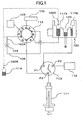
- FIG. 1 is a drawing illustrating an exemplary sample injection device.
- the exemplary sample injection device shown in FIG. 1 includes a sample injection needle 100 (100A through 100C), a pump 103, a syringe 111, a wash liquid pump 112, a valve 113, a sample container 114, an injection valve (switching valve) 115, a cleaning device 120, a sample injection port 124, and a needle moving unit (not shown).
- the injection valve 115 has six ports to which the sample injection needle 100, the mobile phase pump 103, the valve 113, the cleaning device 120, and the sample injection port 124 are connected.
- the injection valve 115 switches between a connection mode (connection mode A) indicated by solid lines A in FIG. 1 and a connection mode (connection mode B) indicated by broken lines B in FIG. 1 .
- the injection valve 115 Before analysis of a sample is started, the injection valve 115 is in the connection mode A and the sample injection needle 100 is attached to the sample injection port 124 (the sample injection needle 100 in this position is indicated by the reference number 100A).
- the sample injection needle 100A is connected via the injection valve 115 to the pump 103.
- the sample injection port 124 is connected via piping 125 and the injection valve 115 to a separation column 105.
- connection mode A a mobile phase supplied from the pump 103 is fed into the separation column 105 via the sample injection needle 100A, the sample injection port 124, the piping 125, and the injection valve 115.
- the injection valve 115 is switched to the connection mode B and the sample injection needle 100 is inserted into the sample container 114 (the sample injection needle 100 in this position is indicated by the reference number 100B).
- the sample injection needle 100B is connected to the syringe 111 via the injection valve 115 and the valve 113. Therefore, the sample in the sample container 114 can be drawn into the sample injection needle 100B by operating the syringe 111.
- the pump 103 is connected via the injection valve 115 to the separation column 105 and therefore the mobile phase continues to be supplied to the separation column 105 even when the sample is being drawn into the sample injection needle 100.
- the sample injection needle 100 When feeding the sample drawn into the sample injection needle 100 to the separation column 105, the sample injection needle 100 is inserted into a cleaning unit 117B and then into a cleaning unit 117A of the cleaning device 120 to clean its outer surface. New supplies of a wash liquid are continuously supplied to the cleaning units 117A and 117B of the cleaning device 120 by connecting the valve 113 to the wash liquid pump 112 at specified timings. Excess wash liquid is discharged from a waste liquid port 123.
- the cleaned sample injection needle 100 is inserted into the sample injection port 124 and the injection valve 115 is switched again to the connection mode A.
- the mobile phase supplied from the pump 103 to the sample injection needle 100A pushes the sample out of the sample injection needle 100A into the sample injection port 124.
- the sample is then carried by the flow of the mobile phase via the piping 125 and the injection valve 115 to the separation column 105.
- a sample is sent from the sample injection needle 100A to the separation column 105 through the injection valve 115.
- Carry-over is a problem where a substance in a previously analyzed sample remains in a liquid chromatograph and the remaining substance is detected in a subsequent analysis as if the substance originally exists in the sample used in the subsequent analysis. Thus, carry-over reduces the credibility of analysis results.
- a portion of the sample may adhere to a metal and/or a resin in the sample injection device and remain in the device. Carry-over occurs if the remaining sample is introduced into the analysis system of a liquid chromatograph when a new sample is injected.
- the wash liquid pump 112, the valve 113, the cleaning device 120 are provided to clean the outer surface of the sample injection needle 100 after drawing in a sample, to clean the inner surface of the sample injection needle 100 after injecting the sample, and thereby to prevent the sample from remaining in the sample injection device.
- a general object of the present invention is to provide a sample injection device, a sample injection method, and a liquid chromatograph that substantially obviate one or more problems caused by the limitations and disadvantages of the related art.
- a more particular object of the present invention is to provide a sample injection device, a sample injection method, and a liquid chromatograph that can effectively reduce carry-over.
- a sample injection device includes a sample injection port connected to a column; a mobile phase supplying unit configured to supply a mobile phase; a first sample injection needle attachable to the sample injection port; a second sample injection needle attachable to the sample injection port; a sample-suctioning unit connectable to the first sample injection needle and configured to draw a sample into the first sample injection needle when connected thereto; and a switching valve configured to selectively connect the first sample injection needle to the mobile phase supplying unit or the sample-suctioning unit and to connect the second sample injection needle to the mobile phase supplying unit; wherein the switching valve is configured to connect the first sample injection needle to the mobile phase supplying unit when the first sample injection needle is attached to the sample injection port, and configured to connect the first sample injection needle to the sample-suctioning unit and to connect the second sample injection needle to the mobile phase supplying unit when the second sample injection needle is attached to the sample injection port.
- the switching valve is switched to connect the first sample injection needle to the mobile phase supplying unit.
- the mobile phase from the mobile phase supplying unit is fed into the column via the first sample injection needle and the sample injection port.
- the switching valve is switched to connect the first sample injection needle to the sample-suctioning unit and to connect the second sample injection needle to the mobile phase supplying unit.
- the mobile phase from the mobile phase supplying unit is fed into the column via the second sample injection needle and the sample injection port.
- the sample can be drawn into the first sample injection needle by operating the sample-suctioning unit.
- the column can be isolated from the switching valve.
- the above configuration makes it possible to constantly feed the mobile phase into the column from the first or second sample injection needle connected to the mobile phase supplying unit without connecting the column to the switching valve.
- This makes it possible to feed a sample into the column without making the sample go through the switching valve by attaching the first sample injection needle containing the sample to the sample injection port and thereby to prevent the sample from remaining in the switching valve as with a conventional sample injection device.
- the sample injection device of the present invention may also include a valve disposed in the path of piping connecting the second sample injection needle and the switching valve and configured to block the piping when the second sample injection needle is detached from the sample injection port.
- the valve provided in the path of piping connecting the second sample injection needle and the switching valve prevents leakage of the mobile phase from the second sample injection needle when the second sample injection needle is detached from the sample injection port.
- a method of injecting a sample into a column using the sample injection device described above includes a first step of attaching the first sample injection needle to the sample injection port, connecting the first sample injection needle via the switching valve to the mobile phase supplying unit, and disconnecting the second sample injection needle; a second step of drawing the sample into the first sample injection needle by connecting the first sample injection needle via the switching valve to the sample-suctioning unit, attaching the second sample injection needle to the sample injection port, and connecting the second sample injection needle via the switching valve to the mobile phase supplying unit; and a third step of attaching the first sample injection needle to the sample injection port, feeding the sample drawn into the first sample injection needle into the column by connecting the first sample injection needle via the switching valve to the mobile phase supplying unit, and disconnecting the second sample injection needle.
- the first sample injection needle is attached to the sample injection port and, at the same time, connected to the mobile phase supplying unit via the switching valve. Therefore, the mobile phase is fed into the column via the first sample injection needle.
- the second sample injection needle is disconnected from other components and is not used.
- the second sample injection needle connected via the switching valve to the mobile phase supplying unit is attached to the sample injection port. Therefore, the mobile phase is fed into the column via the second sample injection needle. Also, since the first sample injection needle is connected via the switching valve to the sample-suctioning unit, the sample can be drawn into the first sample injection needle.
- the first sample injection needle containing the drawn-in sample is attached to the sample injection port and, at the same time, connected to the mobile phase supplying unit via the switching valve. Therefore, the sample is fed into the column without going through the switching valve. This makes it possible to prevent a sample from remaining in the switching valve as with a conventional method.
- a valve may be provided in the path of piping connecting the second sample injection needle and the switching valve and the piping may be blocked by the valve in the first and third steps.
- a liquid chromatograph may include a sample injection port connected to a column; a mobile phase supplying unit configured to supply a mobile phase; a first sample injection needle attachable to the sample injection port; a second sample injection needle attachable to the sample injection port; a sample-suctioning unit connectable to the first sample injection needle and configured to draw a sample into the first sample injection needle when connected thereto; a switching valve configured to selectively connect the first sample injection needle to the mobile phase supplying unit or the sample-suctioning unit and to connect the first sample injection needle to the mobile phase supplying unit; a separation column into which the mobile phase and the sample are fed from the first sample injection needle and which is configured to separate components of the sample; and a detector configured to detect the components of the sample separated by the separation column; wherein the switching valve is configured to connect the first sample injection needle to the mobile phase supplying unit when the first sample injection needle is attached to the sample injection port, and configured to connect the first sample injection needle to the sample-suctioning unit and to connect the
- This configuration makes it possible to feed a sample into the column without making the sample go through the switching valve by attaching the first sample injection needle containing the drawn-in sample to the sample injection port ,and thereby to prevent the sample from remaining in the switching valve as with a conventional liquid chromatograph.
- the liquid chromatograph of the present invention makes it possible to reduce carry-over and thereby to improve the accuracy of sample analysis.
- the present invention makes it possible to prevent a sample from remaining in a switching valve and thereby to sufficiently reduce carry-over. Also, according to the present invention, a sample is sent from an injection port to the inlet of a column without going through a switching valve. This configuration makes it possible to minimize the diffusion of a sample and thereby to increase the number of theoretical plates of a detected peak.
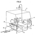
- FIG. 2 is a perspective view illustrating a configuration of a sample injection device 1 according to an embodiment of the present invention.
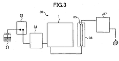
- FIG. 3 is a block diagram illustrating a configuration of a liquid chromatograph 30 including the sample injection device 1. The configuration of the liquid chromatograph 30 is described first with reference to FIG. 3 .
- the liquid chromatograph 30 includes a mobile phase reservoir 31 for holding a liquid used as a mobile phase, a mobile phase deaerator 32 for removing air from the liquid mobile phase, a pump 33 (that corresponds to a mobile phase supplying unit described in claims) for feeding the liquid mobile phase from the mobile phase reservoir 31 to a detector 37, a sample injection device 1 for injecting a sample into the liquid mobile phase being sent to a separation column 35, the separation column 35 filled with a filler for separating components of the sample, a constant-temperature bath 36 for maintaining the separation column 35 at a constant temperature, and the detector 37 for detecting eluted components of the sample.
- the mobile phase is fed by the pump 33 from the mobile phase reservoir 31 via the sample injection device 1 to the separation column 35.
- the mobile phase is preferably supplied to the separation column 35 continuously so that sample analysis can be performed stably.
- the sample injection device 1 includes first and second sample injection needles 10A and 10B, a syringe 11 (that corresponds to a sample-suctioning unit described in claims), a wash liquid pump 12, a valve 13, a sample container 14, an injection valve 15, a wash liquid container 18, a cleaning device 20, and a needle moving unit (not shown).
- the sample injection device 1 of this embodiment is characterized by having two sample injection needles 10A and 10B.
- the first sample injection needle 10A can be connected to the syringe 11 via the injection valve 15 and the valve 13. Also, the first sample injection needle 10A can be connected to the pump 33 via the injection valve 15.
- the first sample injection needle 10A When the first sample injection needle 10A is connected to the syringe 11 by switching the valves 13 and 15, a sample can be drawn into or withdrawn from the first sample injection needle 10A by pulling or pushing the piston of the syringe 11.
- the injection valve 15 When the injection valve 15 is switched and the first sample injection needle 10A is connected via the injection valve 15 to the pump 33, a mobile phase is fed by the pump 33 to the first sample injection needle 10A.
- the second sample injection needle 10B can also be connected to the pump 33 via the injection valve 15.
- the injection valve 15 is switched and the second sample injection needle 10B is connected via the injection valve 15 to the pump 33, the mobile phase is fed by the pump 33 into the second sample injection needle 10B.
- a drip-preventing three-way solenoid valve 26 is provided in the path of piping connecting the second sample needle 10B and the injection valve 15.
- the drip-preventing three-way solenoid valve 26 closes when the second sample injection needle 10B is not attached to an injection port 19 but, for example, is being moved and the injection valve 15 is switched to a connection mode B shown in FIG. 4 , and thereby prevents the mobile phase from flowing out of the second needle 10B.
- the wash liquid container 18 contains a wash liquid and is connected to the wash liquid pump 12 (the wash liquid container 18 is not shown in FIG. 4 ).
- the wash liquid in the wash liquid container 18 is drawn in and pumped into the valve 13 by the wash liquid pump 12.
- the valve 13 selectively supplies the wash liquid fed from the wash liquid container 18 by the wash liquid pump 12 to the cleaning device 20 or the first sample injection needle 10A. More specifically, the valve 13 includes three ports P1 through P3 two of which can be selectively connected.
- the syringe 11 and the injection valve 15 are both connected to the port P3 of the valve 13. In other words, the syringe 11 and the injection valve 15 are always connected. Also, the valve 13 can be switched to a connection mode where no pair of the ports P1 through P3 is connected to each other.
- the cleaning device 20 includes cleaning units 17A and 17B, an ultrasonic transducer 21, a waste liquid port 23, and waste liquid piping 25.
- a wash liquid water is used in this embodiment
- Excess wash liquid flows into the waste liquid port 23 and is discharged as waste liquid from the waste liquid piping 25 connected to the waste liquid port 23.
- the cleaning device 20 washes away a sample adhering to the first sample injection needle 10A inserted therein and thereby prevents carry-over.
- the ultrasonic transducer 21 provided in the cleaning device 20 enables cleaning the first sample injection needle 10A using ultrasound. This configuration improves the effectiveness of cleaning the first sample injection needle 10A and thereby makes it possible to more effectively prevent carry-over.
- the injection port 19 is connected to the separation column 35.
- the injection port 19 is not connected to but completely separated from the injection valve 15.
- the first sample injection needle 10A containing a sample drawn therein is attached to the injection port 19 and the sample is ejected into the injection port 19. The sample is then carried by the flow of a mobile phase to the separation column 35.
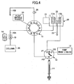
- the injection valve 15 has six ports to which the first sample injection needle 10A, the second sample injection needle 10B, the valve 13, the pump 33, and the cleaning device 20 are connected.
- the injection valve 15 switches between a connection mode indicated by solid lines A in FIG. 4 (hereafter called the connection mode A) and a connection mode indicated by broken lines B in FIG. 4 (hereafter called the connection mode B).
- the first sample injection needle 10A is connected via the injection valve 15 to the pump 33 and the valve 13 is connected via the injection valve 15 to the cleaning unit 17A of the cleaning device 20.
- the second sample injection needle 10B is disconnected from other components.
- the injection valve 15 is in the connection mode B, the first sample injection needle 10A is connected via the injection valve 15 to the valve 13 and the second sample injection needle 10B is connected via the injection valve 15 to the pump 33.
- FIG. 4 shows the sample injection device 1 performing a preparatory step (first step) before drawing a sample into the first sample injection needle 10A.
- the injection valve 15 is in the connection mode A and no pair of the ports P1 through P3 of the valve 13 is connected to each other.
- the first sample injection needle 10A is attached to the injection port 19 by the needle moving unit (not shown).
- the second sample injection needle 10B is placed by the needle moving unit in a waiting position near the injection port 19. In other words, in the preparatory step, the second sample injection needle 10B is disconnected and is not used. Also, the drip-preventing three-way solenoid valve 26 is closed to block the piping connecting the second sample needle 10B and the injection valve 15.
- a mobile phase from the pump 33 is fed into the separation column 35 via the first sample injection needle 10A and the injection port 19.
- FIG. 5 shows a sample-suctioning step (second step) of drawing a sample into the first sample injection needle 10A.
- the first sample injection needle 10A is inserted into the sample container 14 by the needle moving unit and the second sample injection needle 10B is attached to the injection port 19 in place of the first sample injection needle 10A.
- the injection valve 15 is switched to the connection mode B. Also, the drip-preventing three-way solenoid valve 26 is opened to connect the second sample injection needle 10B and the injection valve 15.
- the mobile phase from the pump 33 is fed into the separation column 35 via the second sample injection needle 10B and the injection port 19.
- the mobile phase is constantly fed into the separation column 35.
- the first sample injection needle 10A is connected to the syringe 11 via the injection valve 15 and the valve 13.
- the sample in the sample container 14 is drawn into the first sample injection needle 10A by operating the syringe 11.
- the amount of the sample drawn into the first sample injection needle 10A is predetermined such that the sample does not flow into the injection valve 15. This also prevents a sample from adhering to the inner surface of the injection valve 15 and makes it possible to prevent carry-over.
- the first sample injection needle 10A may have a sample loop to increase the amount of sample that can be drawn into the needle.
- FIGs. 6 and 7 show cleaning steps of washing away a sample that adheres to the outer surface of the first sample injection needle 10A when the needle is dipped into the sample in the sample container 14.
- FIG. 6 shows a pre-cleaning step for roughly washing away a sample adhering to the outer surface of the first sample injection needle 10A.
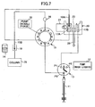
- FIG. 7 shows an ultrasonic-cleaning step for more completely washing away a sample adhering to the outer surface of the first sample injection needle 10A.
- the injection valve 15 is kept in the connection mode B and the first sample injection needle 10A is inserted by the needle moving unit into the cleaning unit 17B of the cleaning device 20.
- the valve 13 is switched to connect the port P1 and Port P2 and thereby to supply the wash liquid in the wash liquid container 18 via the wash liquid pump 12 to the cleaning unit 17B.
- the wash liquid gushes into the cleaning unit 17B and pre-cleans the outer surface of the first sample injection needle 10A.
- the wash liquid overflowing the cleaning unit 17B is discharged via the waste liquid port 23 and the waste liquid piping 25.
- the injection valve 15 is kept in the connection mode B and the first sample injection needle 10A is inserted by the needle moving unit into the cleaning unit 17A of the cleaning device 20.
- the valve 13 is switched to a connection mode where no pair of the ports P1 through P3 is connected to each other.
- the ultrasonic transducer 21 is driven to generate ultrasound.
- the wash liquid in the cleaning unit 17A is vibrated by the ultrasound and the sample adhering to the outer surface of the first sample injection needle 10A is sufficiently washed away.
- the mobile phase from the pump 33 is continuously fed into the separation column 35 via the injection valve 15, the second sample injection needle 10B, and the injection port 19.
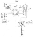
- FIG. 8 shows a sample feeding step (third step) of feeding the sample into the separation column 35.
- the injection valve 15 is switched again from the connection mode B to the connection mode A and the first sample injection needle 10A is attached again to the injection port 19.
- the second sample injection needle 10B is moved by the needle moving unit to a waiting position near the injection port 19.
- the drip-preventing three-way solenoid valve 26 is closed to block the piping connecting the second sample needle 10B and the injection valve 15. Also, in the sample feeding step (third step), the first sample injection needle 10A containing the drawn-in sample is attached to the injection port 19 and connected by the injection valve 15 to the pump 33.
- the sample in the first sample injection needle 10A is fed into the separation column 35 without going through the injection valve 15. Components of the sample fed into the separation column 35 are separated and sent to the detector 37 for analysis.
- the sample injection device 1 and a sample injection method of this embodiment make it possible to effectively prevent a sample from remaining in the injection valve 15 and thereby to effectively prevent carry-over. Also, preventing carry-over in the sample injection device 1 makes it possible to increase the number of theoretical plates.
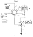
- the wash liquid in the cleaning unit 17A may be renewed during the above sample feeding step (or during the sample analysis).
- the valve 13 is switched to connect the ports P2 and P3 and thereby to supply the wash liquid in the wash liquid container 18 to the cleaning unit 17A of the cleaning device 20 via the wash liquid pump 12, the valve 13, and the injection valve 15.
- the contaminated wash liquid used for cleaning the first sample injection needle 10A is discharged via the waste liquid port 23 and the waste liquid piping 25, and the cleaning unit 17A is filled with a clean, non-contaminated wash liquid.
- This configuration makes it possible to effectively wash away the sample adhering to the outer surface of the first sample injection needle 10A and thereby to prevent carry-over resulting from the remaining sample on the first sample injection needle 10A.
- Carry-over evaluation tests were performed using the liquid chromatograph 30 shown in FIG. 3 including the sample injection device 1 shown in FIGs. 2 and 4 .
- a mixed solvent of CH 3 OH and H 2 O (volume ratio 70:30) was used as the mobile phase for liquid chromatography.
- a mixed solvent of 10 mM of NH 4 H 2 PO 4 containing 100 mM of Na 2 ClO 4 (pH2.6) and CH3CN (volume ratio 55:45) was used as the mobile phase for liquid chromatography.
- the flow speed of the solvents used as the mobile phases were 200 ⁇ l/min. Water was used as the wash liquid.
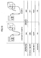
- the example in FIG. 10 shows the results of an evaluation test performed using the sample injection device 1 of this embodiment where a sample drawn into the first sample injection needle 10A is directly fed into the separation column 35 without going through the injection valve 15.
- the comparative example in FIG. 10 shows the results of an evaluation test performed using the conventional injection device (see FIG. 1 ) where a sample drawn into the sample injection needle 100 is fed into the separation column 105 through the injection valve 115.
- the 5% peak width was 0.2374 and the number of theoretical plates was 7659.
- the 5% peak width was 0.2201 and the number of theoretical plates was 8686, which is about 1000 plates larger than that of the comparative example.
- the same column and the same column filler were used and the amounts of the injected sample were also the same. Therefore, the test results indicate that peaks appear sharper and separation can be performed more accurately with the sample injection device 1 of this embodiment than with the conventional sample injection device.
- first through sixth measuring steps were performed.
- chlorhexidine was used as the sample.
- the second through sixth measuring steps only the mobile phase was fed into the column without injecting the sample (chlorhexidine).
- Other conditions were the same as in the evaluation tests shown in FIG. 10 . More specifically, the peak area (S1) of a peak detected in the first measuring step, where a sample was injected, was measured.
- the peak area (S2) of a peak detected in the second measuring step was measured and the proportion of the peak area S2 to the peak area S1 (S2/S1) was calculated.
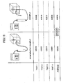
- FIG. 11 shows the results of evaluation tests performed using the conventional injection device (comparative example) in comparison with the results of evaluation tests performed using the sample injection device 1 of this embodiment (example). Theoretically, it is expected that no peak is detected in the second and subsequent measuring steps. Therefore, a smaller proportion of the peak area S2 to the peak area S1 (hereafter called the peak area proportion) indicates that carry-over is reduced more effectively.
- the average of peak area proportions (S2/S1) obtained in four evaluation tests in the comparative example was 0.0020, and the average of peak area proportions (S2/S1) obtained in four evaluation tests in the example was 0.0009.
- the average peak area proportion of the example was much smaller than that of the comparative example.
Description
- The present invention generally relates to a sample injection device, a sample injection method, and a liquid chromatograph. More particularly, the present invention relates to a sample injection device, a sample injection method, and a liquid chromatograph that control the flow of a mobile phase using a switching valve.
- In a liquid chromatograph, a sample is pressurized together with a liquid used as a mobile phase and sent to a column. Components of the sample are separated in the column, eluted, and then detected by a detector. A typical liquid chromatograph includes a mobile phase reservoir for holding a liquid used as a mobile phase, a mobile phase deaerator for removing air from the liquid mobile phase, a pump for feeding the liquid mobile phase from the mobile phase reservoir to a detector, a sample injection device for injecting a sample into the liquid mobile phase being sent to a separation column, the separation column filled with a filler for separating components of the sample, a constant-temperature bath for maintaining the separation column at a substantially constant temperature, and a detector for detecting eluted components of the sample.
- A sample injection device of a liquid chromatograph has a switching valve, for example, as disclosed in
patent document 1. The disclosed switching valve is configured to allow a sample to be drawn into a sample injection needle when drawing the sample into the sample injection needle and to allow the sample drawn into the sample injection needle to be sent to a column along with a flow of a mobile phase when the sample injection needle is attached to a sample injection port.FIG. 1 is a drawing illustrating an exemplary sample injection device. - The exemplary sample injection device shown in
FIG. 1 includes a sample injection needle 100 (100A through 100C), apump 103, asyringe 111, a washliquid pump 112, avalve 113, asample container 114, an injection valve (switching valve) 115, acleaning device 120, asample injection port 124, and a needle moving unit (not shown). - The
injection valve 115 has six ports to which the sample injection needle 100, themobile phase pump 103, thevalve 113, thecleaning device 120, and thesample injection port 124 are connected. Theinjection valve 115 switches between a connection mode (connection mode A) indicated by solid lines A inFIG. 1 and a connection mode (connection mode B) indicated by broken lines B inFIG. 1 . - Before analysis of a sample is started, the
injection valve 115 is in the connection mode A and the sample injection needle 100 is attached to the sample injection port 124 (the sample injection needle 100 in this position is indicated by thereference number 100A). Thesample injection needle 100A is connected via theinjection valve 115 to thepump 103. Thesample injection port 124 is connected viapiping 125 and theinjection valve 115 to aseparation column 105. - Accordingly, in the connection mode A, a mobile phase supplied from the
pump 103 is fed into theseparation column 105 via thesample injection needle 100A, thesample injection port 124, thepiping 125, and theinjection valve 115. - On the other hand, when drawing a sample into the sample injection needle 100, the
injection valve 115 is switched to the connection mode B and the sample injection needle 100 is inserted into the sample container 114 (the sample injection needle 100 in this position is indicated by thereference number 100B). In the connection mode B, thesample injection needle 100B is connected to thesyringe 111 via theinjection valve 115 and thevalve 113. Therefore, the sample in thesample container 114 can be drawn into thesample injection needle 100B by operating thesyringe 111. Also, in the connection mode B, thepump 103 is connected via theinjection valve 115 to theseparation column 105 and therefore the mobile phase continues to be supplied to theseparation column 105 even when the sample is being drawn into the sample injection needle 100. - When feeding the sample drawn into the sample injection needle 100 to the
separation column 105, the sample injection needle 100 is inserted into acleaning unit 117B and then into acleaning unit 117A of thecleaning device 120 to clean its outer surface. New supplies of a wash liquid are continuously supplied to thecleaning units cleaning device 120 by connecting thevalve 113 to thewash liquid pump 112 at specified timings. Excess wash liquid is discharged from awaste liquid port 123. - Then, the cleaned sample injection needle 100 is inserted into the
sample injection port 124 and theinjection valve 115 is switched again to the connection mode A. As a result, the mobile phase supplied from thepump 103 to thesample injection needle 100A pushes the sample out of thesample injection needle 100A into thesample injection port 124. The sample is then carried by the flow of the mobile phase via thepiping 125 and theinjection valve 115 to theseparation column 105. Thus, in the conventional sample injection device, a sample is sent from thesample injection needle 100A to theseparation column 105 through theinjection valve 115. - [Patent document 1] Japanese Patent Application Publication No.
10-010103 - Meanwhile, with the improvement of detection sensitivity of liquid chromatographs configured as described above, a problem called "carry-over" has arisen. Carry-over is a problem where a substance in a previously analyzed sample remains in a liquid chromatograph and the remaining substance is detected in a subsequent analysis as if the substance originally exists in the sample used in the subsequent analysis. Thus, carry-over reduces the credibility of analysis results.
- When a sample is injected into a liquid used as a mobile phase by a sample injection device, a portion of the sample may adhere to a metal and/or a resin in the sample injection device and remain in the device. Carry-over occurs if the remaining sample is introduced into the analysis system of a liquid chromatograph when a new sample is injected.
- In the conventional sample injection device described above, the
wash liquid pump 112, thevalve 113, thecleaning device 120 are provided to clean the outer surface of the sample injection needle 100 after drawing in a sample, to clean the inner surface of the sample injection needle 100 after injecting the sample, and thereby to prevent the sample from remaining in the sample injection device. Although such a configuration can reduce carry-over to a certain extent, it is not effective enough to perform a high-precision analysis. - A general object of the present invention is to provide a sample injection device, a sample injection method, and a liquid chromatograph that substantially obviate one or more problems caused by the limitations and disadvantages of the related art.
- A more particular object of the present invention is to provide a sample injection device, a sample injection method, and a liquid chromatograph that can effectively reduce carry-over.
- To achieve the above objects of the present invention, a sample injection device includes a sample injection port connected to a column; a mobile phase supplying unit configured to supply a mobile phase; a first sample injection needle attachable to the sample injection port; a second sample injection needle attachable to the sample injection port; a sample-suctioning unit connectable to the first sample injection needle and configured to draw a sample into the first sample injection needle when connected thereto; and a switching valve configured to selectively connect the first sample injection needle to the mobile phase supplying unit or the sample-suctioning unit and to connect the second sample injection needle to the mobile phase supplying unit; wherein the switching valve is configured to connect the first sample injection needle to the mobile phase supplying unit when the first sample injection needle is attached to the sample injection port, and configured to connect the first sample injection needle to the sample-suctioning unit and to connect the second sample injection needle to the mobile phase supplying unit when the second sample injection needle is attached to the sample injection port.
- According to the above invention, when the first sample injection needle is attached to the sample injection port, the switching valve is switched to connect the first sample injection needle to the mobile phase supplying unit. As a result, the mobile phase from the mobile phase supplying unit is fed into the column via the first sample injection needle and the sample injection port.
- On the other hand, when the second sample injection needle is attached to the sample injection port, the switching valve is switched to connect the first sample injection needle to the sample-suctioning unit and to connect the second sample injection needle to the mobile phase supplying unit. As a result, the mobile phase from the mobile phase supplying unit is fed into the column via the second sample injection needle and the sample injection port. Also, since the first sample injection needle is connected to the sample-suctioning unit, the sample can be drawn into the first sample injection needle by operating the sample-suctioning unit.
- With the above configuration where the first or second sample injection needle can be selectively attached to the sample injection port, the column can be isolated from the switching valve. In other words, the above configuration makes it possible to constantly feed the mobile phase into the column from the first or second sample injection needle connected to the mobile phase supplying unit without connecting the column to the switching valve. This in turn makes it possible to feed a sample into the column without making the sample go through the switching valve by attaching the first sample injection needle containing the sample to the sample injection port and thereby to prevent the sample from remaining in the switching valve as with a conventional sample injection device.
- The sample injection device of the present invention may also include a valve disposed in the path of piping connecting the second sample injection needle and the switching valve and configured to block the piping when the second sample injection needle is detached from the sample injection port.
- The valve provided in the path of piping connecting the second sample injection needle and the switching valve prevents leakage of the mobile phase from the second sample injection needle when the second sample injection needle is detached from the sample injection port.
- To achieve the above objects of the present invention, a method of injecting a sample into a column using the sample injection device described above includes a first step of attaching the first sample injection needle to the sample injection port, connecting the first sample injection needle via the switching valve to the mobile phase supplying unit, and disconnecting the second sample injection needle; a second step of drawing the sample into the first sample injection needle by connecting the first sample injection needle via the switching valve to the sample-suctioning unit, attaching the second sample injection needle to the sample injection port, and connecting the second sample injection needle via the switching valve to the mobile phase supplying unit; and a third step of attaching the first sample injection needle to the sample injection port, feeding the sample drawn into the first sample injection needle into the column by connecting the first sample injection needle via the switching valve to the mobile phase supplying unit, and disconnecting the second sample injection needle.
- In the first step of the above method, the first sample injection needle is attached to the sample injection port and, at the same time, connected to the mobile phase supplying unit via the switching valve. Therefore, the mobile phase is fed into the column via the first sample injection needle. In this step, the second sample injection needle is disconnected from other components and is not used.
- In the second step, the second sample injection needle connected via the switching valve to the mobile phase supplying unit is attached to the sample injection port. Therefore, the mobile phase is fed into the column via the second sample injection needle. Also, since the first sample injection needle is connected via the switching valve to the sample-suctioning unit, the sample can be drawn into the first sample injection needle.
- In the third step, the first sample injection needle containing the drawn-in sample is attached to the sample injection port and, at the same time, connected to the mobile phase supplying unit via the switching valve. Therefore, the sample is fed into the column without going through the switching valve. This makes it possible to prevent a sample from remaining in the switching valve as with a conventional method.
- In the above method of the present invention, a valve may be provided in the path of piping connecting the second sample injection needle and the switching valve and the piping may be blocked by the valve in the first and third steps.
- With this configuration, the piping connecting the second sample injection needle and the switching valve is blocked by the valve when the second sample injection needle is not attached to the sample injection port so as to prevent leakage of the mobile phase from the second sample injection needle.
- According to the present invention, a liquid chromatograph may include a sample injection port connected to a column; a mobile phase supplying unit configured to supply a mobile phase; a first sample injection needle attachable to the sample injection port; a second sample injection needle attachable to the sample injection port; a sample-suctioning unit connectable to the first sample injection needle and configured to draw a sample into the first sample injection needle when connected thereto; a switching valve configured to selectively connect the first sample injection needle to the mobile phase supplying unit or the sample-suctioning unit and to connect the first sample injection needle to the mobile phase supplying unit; a separation column into which the mobile phase and the sample are fed from the first sample injection needle and which is configured to separate components of the sample; and a detector configured to detect the components of the sample separated by the separation column; wherein the switching valve is configured to connect the first sample injection needle to the mobile phase supplying unit when the first sample injection needle is attached to the sample injection port, and configured to connect the first sample injection needle to the sample-suctioning unit and to connect the second sample injection needle to the mobile phase supplying unit when the second sample injection needle is attached to the sample injection port.
- This configuration makes it possible to feed a sample into the column without making the sample go through the switching valve by attaching the first sample injection needle containing the drawn-in sample to the sample injection port ,and thereby to prevent the sample from remaining in the switching valve as with a conventional liquid chromatograph. Thus, the liquid chromatograph of the present invention makes it possible to reduce carry-over and thereby to improve the accuracy of sample analysis.
- The present invention makes it possible to prevent a sample from remaining in a switching valve and thereby to sufficiently reduce carry-over. Also, according to the present invention, a sample is sent from an injection port to the inlet of a column without going through a switching valve. This configuration makes it possible to minimize the diffusion of a sample and thereby to increase the number of theoretical plates of a detected peak.
-
-
FIG. 1 is a schematic diagram illustrating an exemplary sample injection device; -
FIG. 2 is a schematic diagram illustrating a sample injection device according to an embodiment of the present invention; -
FIG. 3 is a schematic diagram illustrating a liquid chromatograph including the sample injection device according to an embodiment of the present invention; -
FIG. 4 is a drawing used to describe a preparatory step of an exemplary sample injection method using the sample injection device according to an embodiment of the present invention; -
FIG. 5 is a drawing used to describe a sample-suctioning step of the exemplary sample injection method using the sample injection device according to an embodiment of the present invention; -
FIG. 6 is a drawing used to describe a pre-cleaning step of the exemplary sample injection method using the sample injection device according to an embodiment of the present invention where a sample injection needle is pre-cleaned; -
FIG. 7 is a drawing used to describe an ultrasonic-cleaning step of the exemplary sample injection method using the sample injection device according to an embodiment of the present invention where a sample injection needle is ultrasonically cleaned; -
FIG. 8 is a drawing used to describe a sample analysis step of the exemplary sample injection method using the sample injection device according to an embodiment of the present invention (1); -
FIG. 9 is a drawing used to describe the sample analysis step of the exemplary sample injection method using the sample injection device according to an embodiment of the present invention (2); -
FIG. 10 is a table used to describe advantageous effects of the present invention (1) ; and -
FIG. 11 is a table used to describe advantageous effects of the present invention (2). -
- 1 Sample injection device
- 10A, 10B Sample injection needle
- 11 Syringe
- 12 Wash liquid pump
- 13 Valve
- 14 Sample container
- 15 Injection valve
- 17A, 17B Cleaning unit
- 18 Wash liquid container
- 19 Injection port
- 20 Cleaning device
- 26 Drip-preventing three-way solenoid valve
- 30 Liquid chromatograph
- 31 Mobile phase reservoir
- 32 Mobile phase deaerator
- 33 Pump
- 35 Separation column
- The best mode for carrying out the invention is described based on the following embodiments with reference to the accompanying drawings.
-
FIG. 2 is a perspective view illustrating a configuration of asample injection device 1 according to an embodiment of the present invention.FIG. 3 is a block diagram illustrating a configuration of aliquid chromatograph 30 including thesample injection device 1. The configuration of theliquid chromatograph 30 is described first with reference toFIG. 3 . - The
liquid chromatograph 30 includes amobile phase reservoir 31 for holding a liquid used as a mobile phase, amobile phase deaerator 32 for removing air from the liquid mobile phase, a pump 33 (that corresponds to a mobile phase supplying unit described in claims) for feeding the liquid mobile phase from themobile phase reservoir 31 to a detector 37, asample injection device 1 for injecting a sample into the liquid mobile phase being sent to aseparation column 35, theseparation column 35 filled with a filler for separating components of the sample, a constant-temperature bath 36 for maintaining theseparation column 35 at a constant temperature, and the detector 37 for detecting eluted components of the sample. The mobile phase is fed by thepump 33 from themobile phase reservoir 31 via thesample injection device 1 to theseparation column 35. The mobile phase is preferably supplied to theseparation column 35 continuously so that sample analysis can be performed stably. - Next, the configuration of the
sample injection device 1 is described with reference toFIGs. 2 and4. FIG. 4 shows how the components of thesample injection device 1 are connected. Thesample injection device 1 includes first and second sample injection needles 10A and 10B, a syringe 11 (that corresponds to a sample-suctioning unit described in claims), awash liquid pump 12, avalve 13, asample container 14, aninjection valve 15, a washliquid container 18, acleaning device 20, and a needle moving unit (not shown). - The
sample injection device 1 of this embodiment is characterized by having two sample injection needles 10A and 10B. The firstsample injection needle 10A can be connected to thesyringe 11 via theinjection valve 15 and thevalve 13. Also, the firstsample injection needle 10A can be connected to thepump 33 via theinjection valve 15. - When the first
sample injection needle 10A is connected to thesyringe 11 by switching thevalves sample injection needle 10A by pulling or pushing the piston of thesyringe 11. When theinjection valve 15 is switched and the firstsample injection needle 10A is connected via theinjection valve 15 to thepump 33, a mobile phase is fed by thepump 33 to the firstsample injection needle 10A. - The second
sample injection needle 10B can also be connected to thepump 33 via theinjection valve 15. When theinjection valve 15 is switched and the secondsample injection needle 10B is connected via theinjection valve 15 to thepump 33, the mobile phase is fed by thepump 33 into the secondsample injection needle 10B. - A drip-preventing three-
way solenoid valve 26 is provided in the path of piping connecting thesecond sample needle 10B and theinjection valve 15. The drip-preventing three-way solenoid valve 26 closes when the secondsample injection needle 10B is not attached to aninjection port 19 but, for example, is being moved and theinjection valve 15 is switched to a connection mode B shown inFIG. 4 , and thereby prevents the mobile phase from flowing out of thesecond needle 10B. - The wash
liquid container 18 contains a wash liquid and is connected to the wash liquid pump 12 (the washliquid container 18 is not shown inFIG. 4 ). The wash liquid in the washliquid container 18 is drawn in and pumped into thevalve 13 by thewash liquid pump 12. - The
valve 13 selectively supplies the wash liquid fed from the washliquid container 18 by thewash liquid pump 12 to thecleaning device 20 or the firstsample injection needle 10A. More specifically, thevalve 13 includes three ports P1 through P3 two of which can be selectively connected. - The
syringe 11 and theinjection valve 15 are both connected to the port P3 of thevalve 13. In other words, thesyringe 11 and theinjection valve 15 are always connected. Also, thevalve 13 can be switched to a connection mode where no pair of the ports P1 through P3 is connected to each other. - The
cleaning device 20 includes cleaningunits ultrasonic transducer 21, awaste liquid port 23, and wasteliquid piping 25. When thevalve 13 is switched and thecleaning device 20 is connected to thewash liquid pump 12, a wash liquid (water is used in this embodiment) is supplied to thecleaning device 20 from the washliquid container 18. Excess wash liquid flows into thewaste liquid port 23 and is discharged as waste liquid from the waste liquid piping 25 connected to thewaste liquid port 23. - As described later, the
cleaning device 20 washes away a sample adhering to the firstsample injection needle 10A inserted therein and thereby prevents carry-over. Theultrasonic transducer 21 provided in thecleaning device 20 enables cleaning the firstsample injection needle 10A using ultrasound. This configuration improves the effectiveness of cleaning the firstsample injection needle 10A and thereby makes it possible to more effectively prevent carry-over. - The
injection port 19 is connected to theseparation column 35. In thesample injection device 1 of this embodiment, theinjection port 19 is not connected to but completely separated from theinjection valve 15. As described later, the firstsample injection needle 10A containing a sample drawn therein is attached to theinjection port 19 and the sample is ejected into theinjection port 19. The sample is then carried by the flow of a mobile phase to theseparation column 35. - The
injection valve 15 has six ports to which the firstsample injection needle 10A, the secondsample injection needle 10B, thevalve 13, thepump 33, and thecleaning device 20 are connected. Theinjection valve 15 switches between a connection mode indicated by solid lines A inFIG. 4 (hereafter called the connection mode A) and a connection mode indicated by broken lines B inFIG. 4 (hereafter called the connection mode B). - When the
injection valve 15 is in the connection mode A, the firstsample injection needle 10A is connected via theinjection valve 15 to thepump 33 and thevalve 13 is connected via theinjection valve 15 to thecleaning unit 17A of thecleaning device 20. In this mode, the secondsample injection needle 10B is disconnected from other components. When theinjection valve 15 is in the connection mode B, the firstsample injection needle 10A is connected via theinjection valve 15 to thevalve 13 and the secondsample injection needle 10B is connected via theinjection valve 15 to thepump 33. - Operations of the
sample injection device 1 configured as described above and a sample injection method of injecting a sample into theseparation column 35 using thesample injection device 1 are described below with reference toFIGs. 4 through 9 . -
FIG. 4 shows thesample injection device 1 performing a preparatory step (first step) before drawing a sample into the firstsample injection needle 10A. In the preparatory step, theinjection valve 15 is in the connection mode A and no pair of the ports P1 through P3 of thevalve 13 is connected to each other. The firstsample injection needle 10A is attached to theinjection port 19 by the needle moving unit (not shown). - The second
sample injection needle 10B is placed by the needle moving unit in a waiting position near theinjection port 19. In other words, in the preparatory step, the secondsample injection needle 10B is disconnected and is not used. Also, the drip-preventing three-way solenoid valve 26 is closed to block the piping connecting thesecond sample needle 10B and theinjection valve 15. - Accordingly, in the preparatory step, a mobile phase from the
pump 33 is fed into theseparation column 35 via the firstsample injection needle 10A and theinjection port 19. -
FIG. 5 shows a sample-suctioning step (second step) of drawing a sample into the firstsample injection needle 10A. In the sample-suctioning step, the firstsample injection needle 10A is inserted into thesample container 14 by the needle moving unit and the secondsample injection needle 10B is attached to theinjection port 19 in place of the firstsample injection needle 10A. Theinjection valve 15 is switched to the connection mode B. Also, the drip-preventing three-way solenoid valve 26 is opened to connect the secondsample injection needle 10B and theinjection valve 15. - Accordingly, in the sample-suctioning step, the mobile phase from the
pump 33 is fed into theseparation column 35 via the secondsample injection needle 10B and theinjection port 19. In other words, even when the secondsample injection needle 10B is attached to theinjection port 19 in place of the firstsample injection needle 10A, the mobile phase is constantly fed into theseparation column 35. This configuration makes it possible to stably perform sample analysis. - Meanwhile, the first
sample injection needle 10A is connected to thesyringe 11 via theinjection valve 15 and thevalve 13. The sample in thesample container 14 is drawn into the firstsample injection needle 10A by operating thesyringe 11. The amount of the sample drawn into the firstsample injection needle 10A is predetermined such that the sample does not flow into theinjection valve 15. This also prevents a sample from adhering to the inner surface of theinjection valve 15 and makes it possible to prevent carry-over. The firstsample injection needle 10A may have a sample loop to increase the amount of sample that can be drawn into the needle. -
FIGs. 6 and7 show cleaning steps of washing away a sample that adheres to the outer surface of the firstsample injection needle 10A when the needle is dipped into the sample in thesample container 14.FIG. 6 shows a pre-cleaning step for roughly washing away a sample adhering to the outer surface of the firstsample injection needle 10A.FIG. 7 shows an ultrasonic-cleaning step for more completely washing away a sample adhering to the outer surface of the firstsample injection needle 10A. - In the pre-cleaning step shown in
FIG. 6 , theinjection valve 15 is kept in the connection mode B and the firstsample injection needle 10A is inserted by the needle moving unit into thecleaning unit 17B of thecleaning device 20. Thevalve 13 is switched to connect the port P1 and Port P2 and thereby to supply the wash liquid in the washliquid container 18 via thewash liquid pump 12 to thecleaning unit 17B. As a result, the wash liquid gushes into thecleaning unit 17B and pre-cleans the outer surface of the firstsample injection needle 10A. The wash liquid overflowing thecleaning unit 17B is discharged via thewaste liquid port 23 and thewaste liquid piping 25. - In the subsequent ultrasonic-cleaning step shown in
FIG. 7 , theinjection valve 15 is kept in the connection mode B and the firstsample injection needle 10A is inserted by the needle moving unit into thecleaning unit 17A of thecleaning device 20. Thevalve 13 is switched to a connection mode where no pair of the ports P1 through P3 is connected to each other. Then, theultrasonic transducer 21 is driven to generate ultrasound. The wash liquid in thecleaning unit 17A is vibrated by the ultrasound and the sample adhering to the outer surface of the firstsample injection needle 10A is sufficiently washed away. Even during the above cleaning steps, the mobile phase from thepump 33 is continuously fed into theseparation column 35 via theinjection valve 15, the secondsample injection needle 10B, and theinjection port 19. - After the cleaning steps, the sample in the first
sample injection needle 10A is fed into theseparation column 35.FIG. 8 shows a sample feeding step (third step) of feeding the sample into theseparation column 35. - In the sample feeding step, the
injection valve 15 is switched again from the connection mode B to the connection mode A and the firstsample injection needle 10A is attached again to theinjection port 19. The secondsample injection needle 10B is moved by the needle moving unit to a waiting position near theinjection port 19. - When the second
sample injection needle 10B is moved, the drip-preventing three-way solenoid valve 26 is closed to block the piping connecting thesecond sample needle 10B and theinjection valve 15. Also, in the sample feeding step (third step), the firstsample injection needle 10A containing the drawn-in sample is attached to theinjection port 19 and connected by theinjection valve 15 to thepump 33. - With this configuration, the sample in the first
sample injection needle 10A is fed into theseparation column 35 without going through theinjection valve 15. Components of the sample fed into theseparation column 35 are separated and sent to the detector 37 for analysis. - Thus, unlike a conventional device and method, the
sample injection device 1 and a sample injection method of this embodiment make it possible to effectively prevent a sample from remaining in theinjection valve 15 and thereby to effectively prevent carry-over. Also, preventing carry-over in thesample injection device 1 makes it possible to increase the number of theoretical plates. - By the way, the wash liquid in the
cleaning unit 17A may be renewed during the above sample feeding step (or during the sample analysis). In this case, as shown inFIG. 9 , thevalve 13 is switched to connect the ports P2 and P3 and thereby to supply the wash liquid in the washliquid container 18 to thecleaning unit 17A of thecleaning device 20 via thewash liquid pump 12, thevalve 13, and theinjection valve 15. - With the new supply of the wash liquid, the contaminated wash liquid used for cleaning the first
sample injection needle 10A is discharged via thewaste liquid port 23 and thewaste liquid piping 25, and thecleaning unit 17A is filled with a clean, non-contaminated wash liquid. This configuration makes it possible to effectively wash away the sample adhering to the outer surface of the firstsample injection needle 10A and thereby to prevent carry-over resulting from the remaining sample on the firstsample injection needle 10A. - Results of carry-over evaluation tests performed on the
liquid chromatograph 1 of the present invention are described below with reference toFIGs. 10 and11 . - Carry-over evaluation tests were performed using the
liquid chromatograph 30 shown inFIG. 3 including thesample injection device 1 shown inFIGs. 2 and4 . In the evaluation tests shown inFIG. 10 , a mixed solvent of CH3OH and H2O (volume ratio 70:30) was used as the mobile phase for liquid chromatography. In the evaluation tests shown inFIG. 11 , a mixed solvent of 10 mM of NH4H2PO4 containing 100 mM of Na2ClO4 (pH2.6) and CH3CN (volume ratio 55:45) was used as the mobile phase for liquid chromatography. The flow speed of the solvents used as the mobile phases were 200 µl/min. Water was used as the wash liquid. - In the evaluation tests shown in
FIGs. 10 and11 , columns having the same dimensions of 2 mm (inner diameter) x 150 mm (length) were used as theseparation column 35 of the example and theseparation column 105 of the comparative example. Theseparation column 35 was maintained at a temperature of 40 °C using the constant-temperature bath 36. In both the example and the comparative example, octadecyl silica gel having a particle diameter of five µm was used as the column filler or the stationary phase for liquid chromatography. As samples for evaluating carry-over, uracil was used in the evaluation tests shown inFIG. 10 and basic and hydrophobic chlorhexidine that is highly likely to cause carry-over was used in the evaluation tests shown inFIG. 11 . As a detector, an absorptiometer using ultraviolet rays with a wavelength of 254 nm was used. - The example in
FIG. 10 shows the results of an evaluation test performed using thesample injection device 1 of this embodiment where a sample drawn into the firstsample injection needle 10A is directly fed into theseparation column 35 without going through theinjection valve 15. The comparative example inFIG. 10 shows the results of an evaluation test performed using the conventional injection device (seeFIG. 1 ) where a sample drawn into the sample injection needle 100 is fed into theseparation column 105 through theinjection valve 115. - In the comparative example, as shown in
FIG. 10 ., the 5% peak width was 0.2374 and the number of theoretical plates was 7659. In the example, the 5% peak width was 0.2201 and the number of theoretical plates was 8686, which is about 1000 plates larger than that of the comparative example. As described above, in the comparative example and the example, the same column and the same column filler were used and the amounts of the injected sample were also the same. Therefore, the test results indicate that peaks appear sharper and separation can be performed more accurately with thesample injection device 1 of this embodiment than with the conventional sample injection device. - In each of the evaluation tests shown in
FIG. 11 , first through sixth measuring steps were performed. In the first measuring step, chlorhexidine was used as the sample. In the second through sixth measuring steps, only the mobile phase was fed into the column without injecting the sample (chlorhexidine). Other conditions were the same as in the evaluation tests shown inFIG. 10 . More specifically, the peak area (S1) of a peak detected in the first measuring step, where a sample was injected, was measured. Next, among the second through sixth measuring steps where only the mobile phase was fed into the column, the peak area (S2) of a peak detected in the second measuring step was measured and the proportion of the peak area S2 to the peak area S1 (S2/S1) was calculated. -
FIG. 11 shows the results of evaluation tests performed using the conventional injection device (comparative example) in comparison with the results of evaluation tests performed using thesample injection device 1 of this embodiment (example). Theoretically, it is expected that no peak is detected in the second and subsequent measuring steps. Therefore, a smaller proportion of the peak area S2 to the peak area S1 (hereafter called the peak area proportion) indicates that carry-over is reduced more effectively. - As shown in
FIG. 11 , the average of peak area proportions (S2/S1) obtained in four evaluation tests in the comparative example was 0.0020, and the average of peak area proportions (S2/S1) obtained in four evaluation tests in the example was 0.0009. Thus, the average peak area proportion of the example was much smaller than that of the comparative example. As the test results inFIG. 10 show, thesample injection device 1 and the sample injection method of this embodiment make it possible to reduce carry-over and thereby to improve the accuracy of sample analysis by theliquid chromatograph 30 including thesample injection device 1. - The present international application is based on Japanese Priority Application No.
2005-015583 filed on January 24, 2005
Claims (5)
- A sample injection device, comprising:a sample injection port (1A) connected to a column (35);a mobile phase supplying unit (33) configured to supply a mobile phase;a first sample injection needle (10A) attachable to the sample injection port;a second sample injection needle (10B) attachable to the sample injection port;a sample-suctioning unit (11) connectable to the first sample injection needle and configured to draw a sample into the first sample injection needle when connected thereto; anda switching valve (15) configured to selectively connect the first sample injection needle to the mobile phase supplying unit or the sample-suctioning unit and to connect the second sample injection needle to the mobile phase supplying unit;
wherein the switching valve is
configured to connect the first sample injection needle to the mobile phase supplying unit when the first sample injection needle is attached to the sample injection port, and
configured to connect the first sample injection needle to the sample-suctioning unit and to connect the second sample injection needle to the mobile phase supplying unit when the second sample injection needle is attached to the sample injection port. - The sample injection device as claimed in claim 1, further comprising:a valve disposed in a path of piping connecting the second sample injection needle and the switching valve and configured to block the piping when the second sample injection needle is detached from the sample injection port.
- A method of injecting a sample into a column using the sample injection device as claimed in claim 1, comprising:a first step of attaching the first sample injection needle to the sample injection port, connecting the first sample injection needle via the switching valve to the mobile phase supplying unit, and disconnecting the second sample injection needle;a second step of drawing the sample into the first sample injection needle by connecting the first sample injection needle via the switching valve to the sample-suctioning unit, attaching the second sample injection needle to the sample injection port, and connecting the second sample injection needle via the switching valve to the mobile phase supplying unit; anda third step of attaching the first sample injection needle to the sample injection port, feeding the sample drawn into the first sample injection needle into the column by connecting the first sample injection needle via the switching valve to the mobile phase supplying unit, and disconnecting the second sample injection needle.
- A method according to claim 3, wherein
a valve is provided in a path of piping connecting the second sample injection needle and the switching valve; and
the piping is blocked by the valve in the first step and the third step. - A liquid chromatograph, comprising:a sample injection device according to claim 1;a separation column into which the mobile phase and the sample are fed from the first sample injection needle and which is configured to separate components of the sample; anda detector configured to detect the components of the sample separated by the separation column.
Applications Claiming Priority (2)
| Application Number | Priority Date | Filing Date | Title |
|---|---|---|---|
| JP2005015583A JP4426979B2 (en) | 2005-01-24 | 2005-01-24 | Sample injection apparatus, sample injection method, and liquid chromatography apparatus |
| PCT/JP2006/300887 WO2006077985A1 (en) | 2005-01-24 | 2006-01-20 | Sample injector, sample injecting method and liquid chromatography equipment |
Publications (3)
| Publication Number | Publication Date |
|---|---|
| EP1843153A1 EP1843153A1 (en) | 2007-10-10 |
| EP1843153A4 EP1843153A4 (en) | 2009-09-02 |
| EP1843153B1 true EP1843153B1 (en) | 2010-05-05 |
Family
ID=36692365
Family Applications (1)
| Application Number | Title | Priority Date | Filing Date |
|---|---|---|---|
| EP06712112A Expired - Fee Related EP1843153B1 (en) | 2005-01-24 | 2006-01-20 | Sample injector, sample injecting method and liquid chromatography device |
Country Status (6)
| Country | Link |
|---|---|
| EP (1) | EP1843153B1 (en) |
| JP (1) | JP4426979B2 (en) |
| KR (1) | KR101195092B1 (en) |
| CN (1) | CN101107518B (en) |
| DE (1) | DE602006014089D1 (en) |
| WO (1) | WO2006077985A1 (en) |
Families Citing this family (9)
| Publication number | Priority date | Publication date | Assignee | Title |
|---|---|---|---|---|
| JP4887199B2 (en) * | 2007-04-09 | 2012-02-29 | 株式会社日立ハイテクノロジーズ | Liquid chromatography |
| KR100895981B1 (en) | 2007-08-06 | 2009-05-07 | 주식회사 휴텍스 | A System and a Method for Sample Injecting Automatically for Chromatography |
| KR101538662B1 (en) * | 2008-08-01 | 2015-07-22 | 가부시키가이샤 시세이도 | Sample injection device, sample injection method, and liquid chromatography device |
| US8939018B2 (en) * | 2008-10-03 | 2015-01-27 | Arkray, Inc. | Analyzing device and method for controlling same |
| JP4933665B1 (en) | 2011-01-14 | 2012-05-16 | 株式会社 資生堂 | Sample injection apparatus, sample injection method, and liquid chromatography apparatus |
| CN104265952B (en) * | 2014-10-24 | 2016-08-17 | 北京佰纯润宇生物科技有限公司 | A kind of eight lead to valve and a kind of tomographic system leading to valve based on eight |
| WO2017130430A1 (en) * | 2016-01-26 | 2017-08-03 | 株式会社島津製作所 | Chromatograph device |
| JP6889425B2 (en) * | 2018-03-14 | 2021-06-18 | 株式会社島津製作所 | Waste liquid monitoring device |
| CN110455970B (en) * | 2019-08-20 | 2021-07-23 | 大连依利特分析仪器有限公司 | Sampling fraction collecting device and system |
Family Cites Families (9)
| Publication number | Priority date | Publication date | Assignee | Title |
|---|---|---|---|---|
| US4022065A (en) * | 1976-02-19 | 1977-05-10 | Ramin James A | Calibrated sample delivery apparatus accommodating offset error |
| US4182184A (en) * | 1978-12-14 | 1980-01-08 | Rheodyne Incorporated | Sample injector |
| JPS62176756U (en) * | 1986-04-30 | 1987-11-10 | ||
| FR2705582B1 (en) | 1993-05-25 | 1995-06-30 | Commissariat Energie Atomique | Automatic column chromatography treatment device and liquid detector usable in such a device. |
| US6155123A (en) * | 1998-04-17 | 2000-12-05 | Rheodyne, L.P. | Multivalving sample injection system |
| US5993654A (en) * | 1998-09-24 | 1999-11-30 | Eldex Laboratories, Inc. | Pressurized liquid delivery apparatus |
| JP2002228668A (en) | 2001-01-31 | 2002-08-14 | Shimadzu Corp | Automatic sampler |
| JP2003075419A (en) * | 2001-09-03 | 2003-03-12 | Shiseido Co Ltd | Liquid chromatographic apparatus and sample injection device and apparatus and method for cleaning |
| CN1788198A (en) * | 2003-05-15 | 2006-06-14 | 株式会社资生堂 | Specimen filling device, specimen filling method, and liquid chromatography device with the specimen filling device |
-
2005
- 2005-01-24 JP JP2005015583A patent/JP4426979B2/en not_active Expired - Fee Related
-
2006
- 2006-01-20 DE DE602006014089T patent/DE602006014089D1/en active Active
- 2006-01-20 EP EP06712112A patent/EP1843153B1/en not_active Expired - Fee Related
- 2006-01-20 WO PCT/JP2006/300887 patent/WO2006077985A1/en active Application Filing
- 2006-01-20 CN CN2006800030015A patent/CN101107518B/en not_active Expired - Fee Related
- 2006-01-20 KR KR1020077016405A patent/KR101195092B1/en not_active IP Right Cessation
Also Published As
| Publication number | Publication date |
|---|---|
| CN101107518B (en) | 2011-11-30 |
| JP4426979B2 (en) | 2010-03-03 |
| JP2006201121A (en) | 2006-08-03 |
| KR101195092B1 (en) | 2012-10-29 |
| WO2006077985A1 (en) | 2006-07-27 |
| EP1843153A4 (en) | 2009-09-02 |
| EP1843153A1 (en) | 2007-10-10 |
| DE602006014089D1 (en) | 2010-06-17 |
| KR20070097068A (en) | 2007-10-02 |
| CN101107518A (en) | 2008-01-16 |
Similar Documents
| Publication | Publication Date | Title |
|---|---|---|
| US7555937B2 (en) | Sample injection device, sample injection method, and liquid chromatograph | |
| EP1843153B1 (en) | Sample injector, sample injecting method and liquid chromatography device | |
| JP5111476B2 (en) | Liquid sample analyzer and liquid sample introduction device | |
| EP2362214A1 (en) | Sample injection device, sample injection method, and liquid chromatography device | |
| CN104833745B (en) | Method for injecting sample into analyzing branch of liquid-chromatography system | |
| WO2010026742A1 (en) | Liquid chromatograph | |
| KR101100094B1 (en) | Specimen filling device, specimen filling method, and liquid chromatography device with the specimen filling device | |
| JP2010117378A (en) | Method of washing probe in clinical tester | |
| CN103238066A (en) | Liquid chromatograph, sample introduction device for liquid chromatograph, and method for cleaning sample introduction device for liquid chromatograph | |
| CN101680823A (en) | Sample introduction method | |
| WO2011129827A1 (en) | Apparatus and method for coupled lc-nmr analysis | |
| KR101686455B1 (en) | Sample injection device, sample injection method, and liquid chromatography device | |
| KR20030020234A (en) | Liquid chromatography system and sample injector and cleaning device and method for cleaning | |
| CN1312472C (en) | Automatic sampling device and method for washing needle thereof | |
| JP4946647B2 (en) | Sample pretreatment device and liquid chromatograph device | |
| JPS6250659A (en) | Introducing method for sample into liquid chromatography | |
| CN102171560A (en) | Analyzing device and method for controlling same | |
| JP4603203B2 (en) | Liquid chromatograph | |
| EP1329705A2 (en) | Pipette- and cartridge-comprising set and related application methods | |
| JP5202272B2 (en) | Liquid chromatograph, liquid chromatograph feed pump, and liquid chromatograph cleaning method | |
| CN103969349A (en) | A washing method of inspection equipment and the inspection equipment thereof | |
| WO2003060509A1 (en) | Pulse cleaning apparatus and method for analytical systems | |
| DE102009026640A1 (en) | Sample collecting device for receiving fluid sample, has sample loop for receiving sample volume, sample collecting needle connected with sample loop, and seating device for mounting sample collecting needle in detachable manner | |
| JP2009002672A (en) | Sample introducing method for chromatograph apparatus and sample introducing device | |
| JPH05240846A (en) | Cation measuring method |
Legal Events
| Date | Code | Title | Description |
|---|---|---|---|
| PUAI | Public reference made under article 153(3) epc to a published international application that has entered the european phase |
Free format text: ORIGINAL CODE: 0009012 |
|
| 17P | Request for examination filed |
Effective date: 20070716 |
|
| AK | Designated contracting states |
Kind code of ref document: A1 Designated state(s): DE FR GB IT |
|
| DAX | Request for extension of the european patent (deleted) | ||
| RBV | Designated contracting states (corrected) |
Designated state(s): DE FR GB IT |
|
| A4 | Supplementary search report drawn up and despatched |
Effective date: 20090804 |
|
| GRAP | Despatch of communication of intention to grant a patent |
Free format text: ORIGINAL CODE: EPIDOSNIGR1 |
|
| RIC1 | Information provided on ipc code assigned before grant |
Ipc: G01N 30/20 20060101AFI20091027BHEP Ipc: G01N 30/24 20060101ALI20091027BHEP |
|
| RTI1 | Title (correction) |
Free format text: SAMPLE INJECTOR, SAMPLE INJECTING METHOD AND LIQUID CHROMATOGRAPHY DEVICE |
|
| GRAS | Grant fee paid |
Free format text: ORIGINAL CODE: EPIDOSNIGR3 |
|
| GRAA | (expected) grant |
Free format text: ORIGINAL CODE: 0009210 |
|
| AK | Designated contracting states |
Kind code of ref document: B1 Designated state(s): DE FR GB IT |
|
| REG | Reference to a national code |
Ref country code: GB Ref legal event code: FG4D |
|
| REF | Corresponds to: |
Ref document number: 602006014089 Country of ref document: DE Date of ref document: 20100617 Kind code of ref document: P |
|
| PLBE | No opposition filed within time limit |
Free format text: ORIGINAL CODE: 0009261 |
|
| STAA | Information on the status of an ep patent application or granted ep patent |
Free format text: STATUS: NO OPPOSITION FILED WITHIN TIME LIMIT |
|
| 26N | No opposition filed |
Effective date: 20110208 |
|
| REG | Reference to a national code |
Ref country code: DE Ref legal event code: R097 Ref document number: 602006014089 Country of ref document: DE Effective date: 20110207 |
|
| REG | Reference to a national code |
Ref country code: FR Ref legal event code: PLFP Year of fee payment: 11 |
|
| PGFP | Annual fee paid to national office [announced via postgrant information from national office to epo] |
Ref country code: DE Payment date: 20160126 Year of fee payment: 11 Ref country code: IT Payment date: 20160122 Year of fee payment: 11 |
|
| PGFP | Annual fee paid to national office [announced via postgrant information from national office to epo] |
Ref country code: FR Payment date: 20160121 Year of fee payment: 11 Ref country code: GB Payment date: 20160122 Year of fee payment: 11 |
|
| REG | Reference to a national code |
Ref country code: DE Ref legal event code: R119 Ref document number: 602006014089 Country of ref document: DE |
|
| GBPC | Gb: european patent ceased through non-payment of renewal fee |
Effective date: 20170120 |
|
| REG | Reference to a national code |
Ref country code: FR Ref legal event code: ST Effective date: 20170929 |
|
| PG25 | Lapsed in a contracting state [announced via postgrant information from national office to epo] |
Ref country code: FR Free format text: LAPSE BECAUSE OF NON-PAYMENT OF DUE FEES Effective date: 20170131 |
|
| PG25 | Lapsed in a contracting state [announced via postgrant information from national office to epo] |
Ref country code: GB Free format text: LAPSE BECAUSE OF NON-PAYMENT OF DUE FEES Effective date: 20170120 Ref country code: DE Free format text: LAPSE BECAUSE OF NON-PAYMENT OF DUE FEES Effective date: 20170801 |
|
| PG25 | Lapsed in a contracting state [announced via postgrant information from national office to epo] |
Ref country code: IT Free format text: LAPSE BECAUSE OF NON-PAYMENT OF DUE FEES Effective date: 20170120 |