EP1843044A1 - Axialkompressor für ein Gasturbinentriebwerk - Google Patents
Axialkompressor für ein Gasturbinentriebwerk Download PDFInfo
- Publication number
- EP1843044A1 EP1843044A1 EP07090067A EP07090067A EP1843044A1 EP 1843044 A1 EP1843044 A1 EP 1843044A1 EP 07090067 A EP07090067 A EP 07090067A EP 07090067 A EP07090067 A EP 07090067A EP 1843044 A1 EP1843044 A1 EP 1843044A1
- Authority
- EP
- European Patent Office
- Prior art keywords
- rotor
- fiber
- axialcompressor
- rotor drum
- wound
- Prior art date
- Legal status (The legal status is an assumption and is not a legal conclusion. Google has not performed a legal analysis and makes no representation as to the accuracy of the status listed.)
- Granted
Links
Images
Classifications
-
- F—MECHANICAL ENGINEERING; LIGHTING; HEATING; WEAPONS; BLASTING
- F04—POSITIVE - DISPLACEMENT MACHINES FOR LIQUIDS; PUMPS FOR LIQUIDS OR ELASTIC FLUIDS
- F04D—NON-POSITIVE-DISPLACEMENT PUMPS
- F04D29/00—Details, component parts, or accessories
- F04D29/26—Rotors specially for elastic fluids
- F04D29/32—Rotors specially for elastic fluids for axial flow pumps
- F04D29/321—Rotors specially for elastic fluids for axial flow pumps for axial flow compressors
-
- F—MECHANICAL ENGINEERING; LIGHTING; HEATING; WEAPONS; BLASTING
- F01—MACHINES OR ENGINES IN GENERAL; ENGINE PLANTS IN GENERAL; STEAM ENGINES
- F01D—NON-POSITIVE DISPLACEMENT MACHINES OR ENGINES, e.g. STEAM TURBINES
- F01D5/00—Blades; Blade-carrying members; Heating, heat-insulating, cooling or antivibration means on the blades or the members
- F01D5/02—Blade-carrying members, e.g. rotors
- F01D5/06—Rotors for more than one axial stage, e.g. of drum or multiple disc type; Details thereof, e.g. shafts, shaft connections
-
- F—MECHANICAL ENGINEERING; LIGHTING; HEATING; WEAPONS; BLASTING
- F01—MACHINES OR ENGINES IN GENERAL; ENGINE PLANTS IN GENERAL; STEAM ENGINES
- F01D—NON-POSITIVE DISPLACEMENT MACHINES OR ENGINES, e.g. STEAM TURBINES
- F01D5/00—Blades; Blade-carrying members; Heating, heat-insulating, cooling or antivibration means on the blades or the members
- F01D5/30—Fixing blades to rotors; Blade roots ; Blade spacers
-
- F—MECHANICAL ENGINEERING; LIGHTING; HEATING; WEAPONS; BLASTING
- F01—MACHINES OR ENGINES IN GENERAL; ENGINE PLANTS IN GENERAL; STEAM ENGINES
- F01D—NON-POSITIVE DISPLACEMENT MACHINES OR ENGINES, e.g. STEAM TURBINES
- F01D5/00—Blades; Blade-carrying members; Heating, heat-insulating, cooling or antivibration means on the blades or the members
- F01D5/30—Fixing blades to rotors; Blade roots ; Blade spacers
- F01D5/3092—Protective layers between blade root and rotor disc surfaces, e.g. anti-friction layers
-
- F—MECHANICAL ENGINEERING; LIGHTING; HEATING; WEAPONS; BLASTING
- F04—POSITIVE - DISPLACEMENT MACHINES FOR LIQUIDS; PUMPS FOR LIQUIDS OR ELASTIC FLUIDS
- F04D—NON-POSITIVE-DISPLACEMENT PUMPS
- F04D29/00—Details, component parts, or accessories
- F04D29/02—Selection of particular materials
- F04D29/023—Selection of particular materials especially adapted for elastic fluid pumps
-
- F—MECHANICAL ENGINEERING; LIGHTING; HEATING; WEAPONS; BLASTING
- F04—POSITIVE - DISPLACEMENT MACHINES FOR LIQUIDS; PUMPS FOR LIQUIDS OR ELASTIC FLUIDS
- F04D—NON-POSITIVE-DISPLACEMENT PUMPS
- F04D29/00—Details, component parts, or accessories
- F04D29/26—Rotors specially for elastic fluids
- F04D29/32—Rotors specially for elastic fluids for axial flow pumps
- F04D29/321—Rotors specially for elastic fluids for axial flow pumps for axial flow compressors
- F04D29/322—Blade mountings
-
- F—MECHANICAL ENGINEERING; LIGHTING; HEATING; WEAPONS; BLASTING
- F05—INDEXING SCHEMES RELATING TO ENGINES OR PUMPS IN VARIOUS SUBCLASSES OF CLASSES F01-F04
- F05D—INDEXING SCHEME FOR ASPECTS RELATING TO NON-POSITIVE-DISPLACEMENT MACHINES OR ENGINES, GAS-TURBINES OR JET-PROPULSION PLANTS
- F05D2300/00—Materials; Properties thereof
- F05D2300/40—Organic materials
- F05D2300/43—Synthetic polymers, e.g. plastics; Rubber
-
- F—MECHANICAL ENGINEERING; LIGHTING; HEATING; WEAPONS; BLASTING
- F05—INDEXING SCHEMES RELATING TO ENGINES OR PUMPS IN VARIOUS SUBCLASSES OF CLASSES F01-F04
- F05D—INDEXING SCHEME FOR ASPECTS RELATING TO NON-POSITIVE-DISPLACEMENT MACHINES OR ENGINES, GAS-TURBINES OR JET-PROPULSION PLANTS
- F05D2300/00—Materials; Properties thereof
- F05D2300/40—Organic materials
- F05D2300/43—Synthetic polymers, e.g. plastics; Rubber
- F05D2300/433—Polyamides, e.g. NYLON
-
- F—MECHANICAL ENGINEERING; LIGHTING; HEATING; WEAPONS; BLASTING
- F05—INDEXING SCHEMES RELATING TO ENGINES OR PUMPS IN VARIOUS SUBCLASSES OF CLASSES F01-F04
- F05D—INDEXING SCHEME FOR ASPECTS RELATING TO NON-POSITIVE-DISPLACEMENT MACHINES OR ENGINES, GAS-TURBINES OR JET-PROPULSION PLANTS
- F05D2300/00—Materials; Properties thereof
- F05D2300/60—Properties or characteristics given to material by treatment or manufacturing
- F05D2300/603—Composites; e.g. fibre-reinforced
Definitions
- the invention relates to an axial compressor, in particular a high-pressure compressor, a medium-pressure compressor or a low-pressure compressor for a gas turbine engine, consisting of a rotor drum driven by the turbine with rotor blades provided on their outer circumference in the respective compressor stage and stator blades following this.
- An axial compressor comprises one or more rotors consisting of rotor blades mounted on the periphery of a shaft driven by the turbine, and a stator blade ring following the rotor in each compressor stage.
- the successive rotors for example by welding, connected to form a drum.
- the rotor blades are usually mounted either in a common, circumferential on the circumference of the rotor shaft groove or in individual juxtaposed axially grooves.
- High centrifugal forces act on the rotor blades which are arranged on a hollow rotor shaft and thus at a distance from the central axis of the compressor, rotating at high speed.
- the loading of the blades by centrifugal forces is counteracted by the formation of the rotor shaft as a rotor disk whose largest mass fraction is close to the compressor axis.
- a plurality of successive rotor disks is, preferably by welding, at the periphery to a - already mentioned above - connected drum.
- the invention has for its object to provide a rotor for the compressor of a gas turbine engine, which has a low weight and can be produced at a reduced cost.
- Core of the invention is the formation of the rotor or the rotor drum with the rotor blades held thereon as a rotor ring, and waiving the usual - space, weight and cost - rotor discs.
- Several rotor rings may be joined together by screw or weld connections to a rotor drum or also form an integrally manufactured rotor drum.
- fiber straps are wound on the rotor ring and the rotor drum, which consist of carbon fibers incorporated into a high-temperature-resistant polymer matrix, wherein high temperature means the prevailing component temperature.
- the im Inside the rotor drum now free space can be used advantageously for installation of a generator or other units.
- the polymer matrix consists of an epoxy resin into which an ester cyanide or a polybismaimide or a polyamideimide or another high-temperature-resistant resin which simultaneously prevents corrosion of the carbon fibers is incorporated.
- the fiber straps which can be used both in axial grooves or in an annular groove held rotor blades and also integrally formed on the rotor ring and the rotor rotor rotor blades are in a formed below the axial grooves Gurt recommendationnut or in a recessed groove or - integrally molded rotor blade - Wrapped near the blade neck on the rotor ring or in a groove formed in this.
- additional fiber straps can be wound on the rotor ring near the blade neck.
- At the inner surface of the rotor drum or the rotor ring can be integrally formed below the blade attachment a bearing surface exhibiting extension piece. On this recording surface more fiber straps can be wound.
- an additional fiber belt can also be wound on the area of the rotor drum following the rotor blade ring in which the stator blades of the compressor are located.
- the Centrifugal absorption straps can simultaneously act as a seal against the guide vanes.
- the carbon fibers are wound after previous wetting with the polymer matrix on the outer surface or in the grooves. They can also be wound up dry, with a polymer then being infiltrated into the winding material.
- the polymeric matrix materials can be both thermosets and thermoplastics.
- the fiber straps are preferably arranged in the first four compressor stages, in which the polymer matrix of the fiber straps is resistant to the temperatures prevailing there. With availability of matrix materials that are resistant to higher temperatures, it is also possible to carry out further stages in this type of construction.
- the fibers have over the height of the fiber belt to the rotor drum gradually increasing elasticity, so as to compensate for the prevailing forces and stresses best.
- a higher polymer content near the rotor surface serves to compensate for the forces acting on the fibers during operation as a result of the thermal expansion of the rotor drum.
- the fibers can also be wound onto a heated rotor drum and / or under reduced pretension.
- piezo fibers connected to a sensor for resistance measurement can be integrated in the fiber belt.
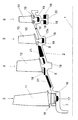
- the individual compressor stages 3 to 6 of the rotor drum 2 which each comprise a forged rotor ring 7 to 10 with rotor blades 11 to 14 arranged on its circumference, can be connected by a welded seam 15 - shown only between the rotor rings 9 and 10.
- a plurality of rotor rings are forged from one piece, so that costly and trouble-prone screw or welded connections can be omitted and the life of the rotor drum 2 so executed is increased.
- the rotor blades 11 of the first compressor stage 3 are each held in axial grooves 16 formed on the circumference of the rotor ring 7.
- a circumferential Gurt qualitynut 17 is formed in the rotor ring 7, in which a fiber belt 18, consisting of embedded in a high-temperature polymer carbon fibers, is located.
- the rotor ring 8 and the rotor blade 12 form in the second compressor stage 4 a one-piece - according to a blisk integrally manufactured - rotor.
- 12 fiber straps 18 are provided on the rotor ring 8 on both sides of the blade root of the rotor blades, which may be wound directly on the rotor ring 8 or in a circumferential groove of the rotor ring 8.
- a recessed annular groove 19 receiving the blade root 13a of the rotor blade 13 is formed, in the lower part of which, in addition to the blade root 13a, a circumferential fiber belt 18 embedded in a polymer matrix Carbon fibers is inserted.
- a fourth embodiment of a rotor in the fourth compressor stage 6 embodies the rotor ring 10, which also has a recessed annular groove 19 according to the third embodiment, but in addition to a T-shaped extension piece 20 has applied fiber straps 18. Furthermore, as in the second embodiment, 10 more fiber straps 18 are mounted on the rotor ring.
- a fifth embodiment is shown in the following on the rotor blades 11 and 12 part of the rotor drum 2, in which the vane ring (not shown) of the first and the second compressor stage is located.
- another fiber belt 21 is flush or slightly protruding over the peripheral surface, which can additionally serve as an inlet seal between the rotor drum 2 and the top edge of the guide vane.
- the fiber straps 21 can also be designed as slip rings and be used for information transmission.
- the fiber straps 18, 21 consist of in the Gurtnessnuten 17 and the recessed annular grooves 19 and / or on the rotor rings 7 to 10 applied in a winding process carbon fibers - matched to the temperature in the first four stages of a high-pressure compressor - in one to 350th ° C heat-resistant polymer matrix, here an ester cyanide, are involved.
- the carbon fibers can - after a polymer wetting - either wet wound, or they are wound up dry and the polymer is infiltrated into the winding material after the winding process.
- the application of the fiber straps is limited to the first stages where the temperature prevailing there does not exceed the temperature allowed for the maximum heat load of the polymer matrix.
- the fiber straps 18 are arranged in the region of the blade root, and thus at the place of origin of the forces and the greatest stresses. The forces can - be absorbed directly by the fiber straps - without the usual necessary discs.
- a gradual fiber structure in the stiffening belts 18, 21 is provided with regard to the mechanical properties. That is, for example, the carbon fibers become gradually inwardly towards the smaller winding radius, gradually more elastic or outwardly towards the larger winding radius, gradually stiffer, so as to compensate for the different voltage input.
- the thermal expansion of the metallic rotor rings 7 to 10 or the rotor drum 2 occurring in the operation of the compressor is taken into account in the formation of the stiffening belts 18, 21 insofar as the fibers are wound either under reduced pretension or on a heated rotor drum.
- a high degree of thermoplastic to create a first, white, winding layer as a placeholder for the thermal expansion of the metallic rotor rings.
- the metallic rotor ring can thereby exploit its strength potential and the reinforcing belt made of fiber material must not absorb the stresses in full.
- piezofibers connected to a sensor may be wrapped in the fiber straps 18, 21. Due to a detected by the sensor resistance change of the piezo fibers with elastic elongation of the quality state of the rotor rings can be monitored.
Landscapes
- Engineering & Computer Science (AREA)
- Mechanical Engineering (AREA)
- General Engineering & Computer Science (AREA)
- Structures Of Non-Positive Displacement Pumps (AREA)
Abstract
Description
- Die Erfindung betrifft einen Axialkompressor, insbesondere einen Hochdruckkompressor, einen Mitteldruckkompressor oder einen Niederdruckkompressor für ein Gasturbinentriebwerk, bestehend aus einer von der Turbine angetriebenen Rotortrommel mit an deren Außenumfang in der jeweiligen Kompressorstufe vorgesehenen Rotorschaufeln und auf diese folgenden Statorschaufeln.
- Ein Axialkompressor umfasst einen oder mehrere Rotoren, die aus am Umfang einer von der Turbine angetriebenen Welle angebrachten Rotorschaufeln bestehen, sowie einen dem Rotor in jeder Kompressorstufe folgenden Statorschaufelkranz. Bei einem aus mehreren - jeweils von einem Rotorschaufelkranz und einem feststehenden Leitschaufelkranz gebildeten - Stufen bestehenden Kompressor sind die aufeinander folgenden Rotoren, beispielsweise durch Schweißen, zu einer Trommel verbunden. Abgesehen von einer so genannten "Blisk", bei der die Schaufeln integral an die Rotorwelle angeformt sind, werden die Rotorschaufeln üblicherweise entweder in einer gemeinsamen, am Umfang der Rotorwelle umlaufenden Nut oder in einzelnen, nebeneinander axial angeordneten Nuten befestigt. Auf die an einer hohlen Rotorwelle und mithin im Abstand von der Mittelachse des Kompressors angeordneten, mit hoher Geschwindigkeit umlaufenden Rotorschaufeln wirken hohe Zentrifugalkräfte. Der Belastung der Schaufeln durch Zentrifugalkräfte wird durch die Ausbildung der Rotorwelle als Rotorscheibe, deren größter Masseanteil sich nahe der Kompressorachse befindet, begegnet. Eine Mehrzahl aufeinander folgender Rotorscheiben wird, vorzugsweise durch Schweißen, an der Peripherie zu einer - bereits oben erwähnten - Trommel verbunden.
- Der wesentliche Nachteil eines derart ausgebildeten Kompressors resultiert aus der zur Kompensation der Fliehkraftbelastung erforderlichen Anordnung der Rotorscheiben, die einen erheblichen Anteil am Gesamtgewicht des Kompressors und letztlich auch des Triebwerks haben und außerdem viel Bauraum beanspruchen, der nicht für andere Zwecke zur Verfügung steht. Schließlich sind der durch die Rotorscheiben verursachte Material- und Fertigungsaufwand und damit auch der Kostenaufwand hoch.
- Der Erfindung liegt die Aufgabe zugrunde, einen Rotor für den Kompressor eines Gasturbinentriebwerks anzugeben, der ein geringes Gewicht aufweist und mit vermindertem Kostenaufwand hergestellt werden kann.
- Erfindungsgemäß wird die Aufgabe mit einem gemäß den Merkmalen des Patentanspruchs 1 ausgebildeten Rotor gelöst. Vorteilhafte Weiterbildungen der Erfindung sind Gegenstand der Unteransprüche.
- Kern der Erfindung ist die Ausbildung des Rotors bzw. der Rotortrommel mit den daran gehaltenen Rotorschaufeln als Rotorring, und zwar unter Verzicht auf die üblichen - platz-, gewichts- und kostenaufwendigen - Rotorscheiben. Mehrere Rotorringe können durch Schraub- oder Schweißverbindungen zu einer Rotortrommel aneinander gefügt sein oder auch eine einstückig gefertigte Rotortrommel bilden. Zum Ausgleich der hohen Fliehkraftbelastung sind auf den Rotorring bzw. die Rotortrommel Fasergurte gewickelt, die aus in eine hochtemperaturbeständige Polymermatrix eingebundenen Kohlefasern bestehen, wobei Hochtemperatur die jeweils herrschende Bauteiltemperatur bedeutet. Der im Innern der Rotortrommel nunmehr freie Raum kann vorteilhaft zum Einbau eines Generators oder anderer Aggregate genutzt werden.
- In Ausgestaltung der Erfindung besteht die Polymermatrix aus einem Epoxidharz, in das ein Estercyanid oder ein Polybismaimid oder ein Polyamidimid oder ein anderes hochtemperaturbeständiges Harz, das gleichzeitig eine Korrosion der Kohlefasern verhindert, eingebunden ist.
- Die Fasergurte, die sowohl bei in Axialnuten oder in einer Ringnut gehaltenen Rotorschaufeln und auch bei an die Rotorring bzw. die Rotortrommel einstückig angeformten Rotorschaufeln eingesetzt werden können, werden in eine unterhalb der Axialnuten ausgebildete Gurtaufnahmenut oder in eine vertiefte Ringnut oder - bei einstückig angeformter Rotorschaufel - nahe dem Schaufelhals auf den Rotorring oder in eine in diesem ausgebildete Nut gewickelt.
- Bei den in Axialnuten oder in einer Ringnut gehaltenen Rotorschaufeln können auf den Rotorring nahe dem Schaufelhals zusätzliche Fasergurte gewickelt werden.
- An die Innenfläche der Rotortrommel bzw. des Rotorringes kann unterhalb der Schaufelbefestigung ein eine Auflagefläche aufweisendes Verlängerungsstück angeformt sein. Auf diese Aufnahmefläche können weitere Fasergurte gewickelt sein.
- In weiterer Ausbildung der Erfindung kann ein zusätzlicher Fasergurt auch auf den dem Rotorschaufelkranz folgenden Bereich der Rotortrommel, in dem sich die Statorschaufeln des Kompressors befinden, gewickelt werden. Die Fliehkraftaufnahmegurte können hier gleichzeitig als Dichtung gegenüber den Leitschaufeln fungieren.
- Die Kohlefasern werden nach vorhergehender Benetzung mit der Polymermatrix auf die Außenfläche bzw. in die Nuten gewickelt. Sie können auch trocken aufgewickelt werden, wobei in das Wickelgut anschließend ein Polymer infiltriert wird. Die polymeren Matrixwerkstoffe können sowohl Duromere wie auch Thermoplaste sein.
- Bei einem Kompressor für ein Triebwerk sind die Fasergurte vorzugsweise in den ersten vier Kompressorstufen angeordnet, in denen die Polymermatrix der Fasergurte gegenüber den dort herrschenden Temperaturen beständig ist. Bei Verfügbarkeit von bei höherer Temperatur beständigen Matrixwerkstoffen können auch weitere Stufen in dieser Bauweise ausgeführt werden. In weiterer Ausbildung der Erfindung weisen die Fasern über die Höhe des Fasergurtes eine zur Rotortrommel hin allmählich steigende Elastizität auf, um so die herrschenden Kräfte und Spannungen am besten ausgleichen zu können.
- Ein nahe der Rotoroberfläche höherer Polymeranteil dient zum Ausgleich der infolge der Wärmedehnung der Rotortrommel im Betrieb auf die Fasern wirkenden Kräfte. Die Fasern können aber auch auf eine erwärmte Rotortrommel und/oder unter verminderter Vorspannung aufgewickelt werden.
- Für das so genannte "health monitoring", das heißt, die Überwachung des Zustands der Rotors, können in den Fasergurt an einen Sensor zur Widerstandsmessung angeschlossene Piezofasern integriert sein.
- Ein Ausführungsbeispiel der Erfindung wird anhand der Zeichnung, in deren einziger Figur eine Teilansicht einer fiktiven Rotortrommel mit unterschiedlichen Schaufel- und Fasergurtvarianten eines vierstufigen Kompressors im Schnitt wiedergegeben ist, näher erläutert.
- In der Zeichnung sind anhand ein und derselben, von einer Turbine angetriebenen und um eine Mittelachse 1 rotierenden - hier für vier verschiedene Schaufelanordnungen fiktiven - Rotortrommel 2 in vier Stufen eines Kompressors, jedoch ohne Leitschaufelkränze, unterschiedliche Ausführungsformen von Fasergurtversteifungen dargestellt.
- Die einzelnen Kompressorstufen 3 bis 6 der Rotortrommel 2, die jeweils einen geschmiedeten Rotorring 7 bis 10 mit an dessen Umfang angeordneten Rotorschaufeln 11 bis 14 umfassen, können durch eine - nur zwischen den Rotorringen 9 und 10 dargestellte - Schweißnaht 15 verbunden sein. Vorzugsweise können jedoch, wie in der Zeichnung dargestellt, mehrere Rotorringe aus einem Stück geschmiedet werden, so dass kostenaufwendige und störanfällige Schraub- oder Schweißverbindungen entfallen können und die Lebensdauer der so ausgeführten Rotortrommel 2 erhöht wird.
- In einer ersten Ausführungsvariante sind die Rotorschaufeln 11 der ersten Kompressorstufe 3 jeweils in am Umfang des Rotorringes 7 ausgebildeten Axialnuten 16 gehalten. Unterhalb der Axialnuten 16 ist in den Rotorring 7 eine umlaufende Gurtaufnahmenut 17 eingeformt, in der sich ein Fasergurt 18, bestehend aus in ein Hochtemperaturpolymer eingebundenen Kohlefasern, befindet.
- In der zweiten Ausführungsvariante bilden der Rotorring 8 und die Rotorschaufel 12 in der zweiten Kompressorstufe 4 einen einstückigen - entsprechend einer Blisk integral gefertigten - Rotor. In diesem Beispiel sind auf dem Rotorring 8 zu beiden Seiten des Schaufelfußes der Rotorschaufeln 12 Fasergurte 18 vorgesehen, die unmittelbar auf den Rotorring 8 oder in eine umlaufende Nut des Rotorringes 8 gewickelt sein können.
- In den Rotorring 9 gemäß der dritten Ausführungsvariante eines Rotors der dritten Kompressorstufe 5 ist eine den Schaufelfuß 13a der Rotorschaufel 13 aufnehmende vertiefte Ringnut 19 eingeformt, in deren unteren Teil zusätzlich, und zwar unterhalb des Schaufelfußes 13a, ein umlaufender Fasergurt 18 aus in eine Polymermatrix eingebetteten Kohlefasern eingelegt ist.
- Eine vierte Ausführungsvariante eines Rotors in der vierten Kompressorstufe 6 verkörpert der Rotorring 10, der ebenfalls eine vertiefte Ringnut 19 gemäß der dritten Ausführungsvariante aufweist, aber zusätzlich auf ein T-förmiges Verlängerungsstück 20 aufgebrachte Fasergurte 18 hat. Des weiteren sind, wie in der zweiten Ausführungsvariante, auf dem Rotorring 10 weitere Fasergurte 18 angebracht.
- Eine fünfte Ausführungsvariante ist in dem auf die Rotorschaufeln 11 und 12 folgenden Teil der Rotortrommel 2, in dem sich der Leitschaufelkranz (nicht dargestellt) der ersten und der zweiten Kompressorstufe befindet, dargestellt. In diesem Bereich der Rotortrommel 2, das heißt, der Rotorringe 7/8 und 8/9 ist ein weiterer Fasergurt 21 bündig oder leicht über die Umfangsfläche überstehend angeordnet, der zusätzlich auch als Einlaufdichtung zwischen der Rotortrommel 2 und der Leitschaufeloberkante dienen kann. Darüber hinaus können die Fasergurte 21 auch als Schleifringe ausgebildet sein und zur Informationsübertragung genutzt werden.
- Die Fasergurte 18, 21 bestehen aus in die Gurtaufnahmenuten 17 bzw. die vertieften Ringnuten 19 und/oder auf die Rotorringe 7 bis 10 in einem Wickelprozess aufgebrachten Kohlefasern, die - abgestimmt auf die Temperatur in den ersten vier Stufen eines Hochdruckkompressors - in eine bis 350°C wärmebeständige Polymermatrix, hier ein Estercyanid, eingebunden sind. Die Kohlefasern können - nach einer Polymerbenetzung - entweder nass aufgewickelt werden, oder sie werden trocken aufgewickelt und das Polymer wird nach dem Wickelprozess in das Wickelgut infiltriert. Bei einem Hochdruckkompressor für ein Gasturbinentriebwerk ist die Anwendung der Fasergurte auf die ersten Stufen beschränkt, in denen die dort herrschende Temperatur nicht die für die maximale Wärmebelastung der Polymermatrix zulässige Temperatur überschreitet.
- Die Fasergurte 18 sind im Bereich des Schaufelfußes angeordnet, und somit am Ort der Entstehung der Kräfte und der größten Spannungen. Die Kräfte können - ohne die üblicherweise notwendigen Scheiben - unmittelbar von der Fasergurten aufgenommen werden.
- Entsprechend dem an der Innenseite der Rotorringe 7 bis 10 bzw. der Rotortrommel 2 größeren Spannungseintrag ist ein hinsichtlich der mechanischen Eigenschaften gradueller Faseraufbau in den Versteifungsgurten 18, 21 vorgesehen. Das heißt beispielsweise, die Kohlefasern werden nach innen, zum kleineren Wickelradius hin, allmählich elastischer bzw. nach außen, zum größeren Wickelradius hin, allmählich steifer, um so den unterschiedlichen Spannungseintrag auszugleichen.
- Die im Betrieb des Kompressors auftretende Wärmedehnung der metallischen Rotorringe 7 bis 10 bzw. der Rotortrommel 2 wird bei der Ausbildung der Versteifungsgurte 18, 21 insofern berücksichtigt, als die Fasern entweder unter verminderter Vorspannung oder auf eine erwärmte Rotortrommel gewickelt werden. Des Weiteren ist es auch denkbar, mit einem hohen Thermoplastanteil eine erste - wei che - Wickellage als Platzhalter für die Wärmedehnung der metallischen Rotorringe zu schaffen. Der metallische Rotorring kann dadurch sein Festigkeitspotential ausschöpfen und der Versteifungsgurt aus Fasermaterial muss die Spannungen nicht in voller Höhe aufnehmen.
- In Verbindung mit dem so genannten "health monitoring" können in die Fasergurte 18, 21 an einen Sensor (nicht dargestellt) angeschlossene Piezofasern eingewickelt sein. Aufgrund einer von dem Sensor erfassten Widerstandsänderung der Piezofasern bei elastischer Dehnung kann der Qualitätszustand der Rotorringe überwacht werden.
-
- 1
- Mittelachse des Kompressors
- 2
- Rotortrommel
- 3 bis 6
- erste bis vierte Kompressorstufe
- 7 bis 10
- Rotorringe von Rotortrommel
- 11 bis 14
- Rotorschaufeln
- 13a
- Schaufelfuß von Rotorschaufel 13
- 15
- Schweißnaht
- 16
- Axialnuten
- 17
- Gurtaufnahmenut
- 18
- Fasergurt
- 19
- vertiefte Ringnut
- 20
- T-förmiges Verlängerungsstück
- 21
- Fasergurt/Dichtung
Claims (14)
- Axialkompressor, insbesondere Hochdruckkompressor für ein Gasturbinentriebwerk, bestehend aus einer von der Turbine angetriebenen Rotortrommel (2) mit an deren Außenumfang in der jeweiligen Kompressorstufe vorgesehenen Rotorschaufeln (11 bis 14) und auf diese folgenden Statorschaufeln, dadurch gekennzeichnet, dass die Rotortrommel (2) aus aneinander gefügten oder zusammen ein einstückiges ringförmiges Bauteil bildenden Rotorringen (7 bis 10) mit auf diesen in Bereichen höchster Fliehkraftbelastung angeordneten Fasergurten (18, 21), bestehend aus auf die Rotortrommel (2) gewickelten, in ein hochtemperaturbeständiges Polymer gebetteten Fasern, gefertigt ist.
- Axialkompressor nach Anspruch 1, dadurch gekennzeichnet, dass die Fasergurte (18, 21) aus auf die Rotorringe gewickelten Kohlefasern bestehen, wobei die Polymermatrix aus einem durch Nasswickeln oder nachträgliches Infiltrieren von trocken gewickelten Kohlefasern eingebrachten, bis 350°C beständigen Epoxidharz besteht.
- Axialkompressor nach Anspruch 2, dadurch gekennzeichnet, dass in das Epoxidharz ein Estercyanid oder ein Polybismaimid oder ein Polyamidimid oder ein anderes hochtemperaturbeständiges Harz, das gleichzeitig die Korrosion der Kohlefasern verhindert, eingebunden ist.
- Axialkompressor nach Anspruch 1, dadurch gekennzeichnet, dass in die Fasergurte (18, 21) Piezofasern eingewickelt sind, die zum Erfassen von auf den Zustand der Rotortrommel (2) zurückzuführenden, durch Längenänderung der Piezofasern bedingten Widerstandsänderungen an einen Sensor angeschlossen sind.
- Axialkompressor nach Anspruch 1, dadurch gekennzeichnet, dass die Fasergurte (18, 21) aus unterschiedlichem Fasermaterial gewickelt sind, wobei die Elastizität des Fasermaterials in den Fasergurten (18, 21) zur Auflagefläche auf der Rotortrommel (2) zunimmt.
- Axialkompressor nach Anspruch, dadurch gekennzeichnet, dass die Fasern zum Ausgleich der Wärmedehnung der Rotortrommel (2) im Betrieb beim Wickeln des Fasergurtes (18, 21) eine verminderte Faservorspannung aufweisen oder auf eine erwärmte Rotortrommel gewickelt sind oder eine innere Lage des Fasergurtes aus einem Thermoplastmaterial als Platzhalter für die Wärmedehnung der Rotortrommel besteht.
- Axialkompressor nach Anspruch 1, dadurch gekennzeichnet, dass die Fasergurte (18) im unmittelbaren Kraftwirkungsbereich der Rotorschaufeln (11 bis 14) auf die Rotortrommel (2) gewickelt sind.
- Axialkompressor nach Anspruch 7, dadurch gekennzeichnet, dass sich die Fasergurte (18) in einer unterhalb von zur Schaufelbefestigung vorgesehenen Axialnuten (16) ausgebildeten Gurtaufnahmenut (17) befinden.
- Axialkompressor nach Anspruch 7, dadurch gekennzeichnet, dass sich die Fasergurte (18) am Boden einer zur Schaufelbefestigung vorgesehen Ringnut (19) unterhalb der in dieser gehaltenen Schaufelfüße befinden.
- Axialkompressor nach Anspruch 8 oder 9, dadurch gekennzeichnet, dass zusätzliche Fasergurte (18) an mindestens einer Seite der Rotorschaufeln (11, 12, 14) auf die Rotortrommel oder -ringe oder in eine Gurtaufnahmenut der Rotortrommel oder -ringe gewickelt sind.
- Axialkompressor nach Anspruch 1, dadurch gekennzeichnet, dass die Rotorschaufeln (13) einstückig an die Rotortrommel oder die Rotorringe angeformt sind und die Fasergurte (18) auf oder in einer Nut der Rotortrommel oder -ringe aufgewickelt sind.
- Axialkompressor nach einem der Ansprüche 8 bis 11, dadurch gekennzeichnet, dass an der Innenseite der Rotortrommel (2) unterhalb der Rotorschaufeln (11 bis 14) ein T-förmiges Verlängerungsstück (19) mit auf die freien Auflageflächen gewickelten Fasergurten (18) angeformt ist.
- Axialkompressor nach Anspruch 1, dadurch gekennzeichnet, dass in dem auf die Rotorschaufeln (11 bis 14) folgenden Bereich gegenüber den Leitschaufeln in einer Nut oder auf der Rotortrommel (2) ein zusätzlich als Einlaufdichtung wirkender Fasergurt (21) aufgewickelt ist.
- Axialkompressor nach Anspruch 1, dadurch gekennzeichnet, dass die ringförmige Ausbildung der Rotortrommel (2) und die Anordnung der Fasergurte (18, 21) in den thermisch weniger belasteten ersten vier Kompressorstufen (3 bis 6) Stufen des Kompressors vorgesehen ist.
Applications Claiming Priority (1)
| Application Number | Priority Date | Filing Date | Title |
|---|---|---|---|
| DE102006015838A DE102006015838A1 (de) | 2006-04-03 | 2006-04-03 | Axialkompressor für ein Gasturbinentriebwerk |
Publications (2)
| Publication Number | Publication Date |
|---|---|
| EP1843044A1 true EP1843044A1 (de) | 2007-10-10 |
| EP1843044B1 EP1843044B1 (de) | 2008-10-08 |
Family
ID=38192434
Family Applications (1)
| Application Number | Title | Priority Date | Filing Date |
|---|---|---|---|
| EP07090067A Ceased EP1843044B1 (de) | 2006-04-03 | 2007-03-29 | Axialkompressor für ein Gasturbinentriebwerk |
Country Status (3)
| Country | Link |
|---|---|
| US (1) | US7918644B2 (de) |
| EP (1) | EP1843044B1 (de) |
| DE (2) | DE102006015838A1 (de) |
Cited By (4)
| Publication number | Priority date | Publication date | Assignee | Title |
|---|---|---|---|---|
| WO2011009433A1 (de) * | 2009-07-21 | 2011-01-27 | Mtu Aero Engines Gmbh | Einlaufbelag zur anordnung an einem gasturbinenbauteil |
| KR20140050564A (ko) * | 2012-10-19 | 2014-04-29 | 아틀라스 코프코 에네르가스 게엠베하 | 유체를 압축하기 위한 터보 기계 |
| EP2818635A1 (de) * | 2013-06-25 | 2014-12-31 | Techspace Aero S.A. | Kompressortrommel einer axialen Turbomaschine mit gemischter Befestigung der Laufradschaufeln |
| EP3020918A1 (de) * | 2014-11-17 | 2016-05-18 | United Technologies Corporation | Verstärkte gasturbinenmotorrotorscheibe |
Families Citing this family (23)
| Publication number | Priority date | Publication date | Assignee | Title |
|---|---|---|---|---|
| DE102008034738A1 (de) * | 2008-07-24 | 2010-01-28 | Rolls-Royce Deutschland Ltd & Co Kg | Verdichterrotor für eine Turbomaschine für den Einsatz im Flugzeugbau |
| US8011877B2 (en) * | 2008-11-24 | 2011-09-06 | General Electric Company | Fiber composite reinforced aircraft gas turbine engine drums with radially inwardly extending blades |
| EP2287445A1 (de) | 2009-07-16 | 2011-02-23 | Techspace Aero S.A. | Rotortrommel eines Axialkompressors mit Verbundgewebe |
| US20110052376A1 (en) * | 2009-08-28 | 2011-03-03 | General Electric Company | Inter-stage seal ring |
| DE102010039796A1 (de) | 2010-06-14 | 2011-12-15 | Max Bögl Bauunternehmung GmbH & Co. KG | Turm mit einem Adapterstück sowie Verfahren zur Herstellung eines Turms mit einem Adapterstück |
| US9169849B2 (en) | 2012-05-08 | 2015-10-27 | United Technologies Corporation | Gas turbine engine compressor stator seal |
| US20140030084A1 (en) * | 2012-07-24 | 2014-01-30 | General Electric Company | Article of manufacture for turbomachine |
| US10036316B2 (en) * | 2012-10-02 | 2018-07-31 | United Technologies Corporation | Geared turbofan engine with high compressor exit temperature |
| WO2014143237A1 (en) | 2013-03-12 | 2014-09-18 | Dierksmeier Douglas D | Active seal system and method of operating a turbomachine |
| US10557352B2 (en) | 2014-09-09 | 2020-02-11 | Rolls-Royce Corporation | Piezoelectric damping rings |
| US9777593B2 (en) | 2015-02-23 | 2017-10-03 | General Electric Company | Hybrid metal and composite spool for rotating machinery |
| US9976429B2 (en) | 2015-06-09 | 2018-05-22 | General Electric Company | Composite disk |
| US10047763B2 (en) | 2015-12-14 | 2018-08-14 | General Electric Company | Rotor assembly for use in a turbofan engine and method of assembling |
| DE102016219815A1 (de) * | 2016-10-12 | 2018-04-12 | Rolls-Royce Deutschland Ltd & Co Kg | Laufschaufelbaugruppe mit ring- oder scheibenförmigem Schaufelträger und radial innenliegender Versteifungsstruktur |
| DE102016219818A1 (de) * | 2016-10-12 | 2018-04-12 | Rolls-Royce Deutschland Ltd & Co Kg | Laufschaufelbaugruppe mit ringsegment- oder scheibensegmentförmigem Schaufelträger und radial innenliegender Versteifungsstruktur |
| FR3057905B1 (fr) * | 2016-10-25 | 2020-06-12 | Safran Aircraft Engines | Piece tournante de turbomachine |
| US10697320B2 (en) | 2017-01-20 | 2020-06-30 | Rolls-Royce Corporation | Piezoelectric vibratory control for static engine components |
| US11092020B2 (en) | 2018-10-18 | 2021-08-17 | Raytheon Technologies Corporation | Rotor assembly for gas turbine engines |
| US11268388B2 (en) * | 2020-04-17 | 2022-03-08 | Raytheon Technologies Corporation | Composite reinforced rotor |
| US11073030B1 (en) | 2020-05-21 | 2021-07-27 | Raytheon Technologies Corporation | Airfoil attachment for gas turbine engines |
| JP2022013322A (ja) * | 2020-07-03 | 2022-01-18 | 三菱重工業株式会社 | タービン |
| FR3151351B1 (fr) * | 2023-07-21 | 2025-06-20 | Safran Aircraft Engines | Dispositif aubagé de turbomachine comportant un dispositif d’aide au positionnement de pied d’aube |
| EP4717877A1 (de) * | 2023-12-19 | 2026-04-01 | Lilium GmbH | Beschaufelte laufscheibe für einen angetriebenen rotor eines triebwerks einer flugzeugantriebseinheit, antriebseinheit für ein flugzeug und flugzeug |
Citations (5)
| Publication number | Priority date | Publication date | Assignee | Title |
|---|---|---|---|---|
| GB1173834A (en) | 1966-11-29 | 1969-12-10 | Rolls Royce | Bladed Rotor for a Fluid Flow Machine |
| GB1296310A (de) * | 1970-05-15 | 1972-11-15 | ||
| FR2143561A1 (de) | 1971-06-29 | 1973-02-09 | Snecma | |
| US6250883B1 (en) * | 1999-04-13 | 2001-06-26 | Alliedsignal Inc. | Integral ceramic blisk assembly |
| EP1406019A1 (de) | 2002-10-02 | 2004-04-07 | Snecma Moteurs | Trommelrotor für eine Turbomaschine |
Family Cites Families (13)
| Publication number | Priority date | Publication date | Assignee | Title |
|---|---|---|---|---|
| GB1170593A (en) * | 1967-04-12 | 1969-11-12 | Rolls Royce | Method of making a Bladed Rotor |
| US3625634A (en) * | 1969-12-10 | 1971-12-07 | Gen Motors Corp | Turbomachine rotor |
| US3610772A (en) * | 1970-05-04 | 1971-10-05 | Gen Motors Corp | Bladed rotor |
| US3966523A (en) * | 1975-08-11 | 1976-06-29 | United Technologies Corporation | Method of making filament reinforced composite rings from plural flat filamentary spiral layers |
| GB1553038A (en) | 1977-04-28 | 1979-09-19 | Snecma | Drum for an axial flow compressor rotor and process for its manufacture |
| DE3037388C1 (de) * | 1980-10-03 | 1982-06-16 | Deutsche Forschungs- und Versuchsanstalt für Luft- und Raumfahrt e.V., 5300 Bonn | Bandage zur radialen Spannung der Segmente eines aus Einzelsegmenten aufgebauten Verdichterlaufrades fuer Gasturbinen |
| US5031497A (en) | 1989-06-29 | 1991-07-16 | Continental Baking Company | Bread slicing machine cleaner |
| DE4324755C1 (de) | 1993-07-23 | 1994-09-22 | Mtu Muenchen Gmbh | Verfahren zur Herstellung faserverstärkter Triebwerkskomponenten |
| US5632600A (en) * | 1995-12-22 | 1997-05-27 | General Electric Company | Reinforced rotor disk assembly |
| US6213720B1 (en) * | 1999-06-11 | 2001-04-10 | Alliedsignal, Inc. | High strength composite reinforced turbomachinery disk |
| DE10218459B3 (de) * | 2002-04-25 | 2004-01-15 | Mtu Aero Engines Gmbh | Verdichter in mehrstufiger Axialbauart |
| DE10350974B4 (de) * | 2003-10-30 | 2014-07-17 | Hottinger Baldwin Messtechnik Gmbh | Aufnehmerelement, Vorrichtung zur Feststellung von Belastungen an Faserverbundwerkstoffbauteilen und Herstellungsverfahren für die Vorrichtung |
| FR2887919B1 (fr) * | 2005-06-29 | 2010-12-31 | Snecma Moteurs | Rotor de turbomachine comprenant au moins un disque renforce par un anneau composite |
-
2006
- 2006-04-03 DE DE102006015838A patent/DE102006015838A1/de not_active Withdrawn
-
2007
- 2007-03-29 EP EP07090067A patent/EP1843044B1/de not_active Ceased
- 2007-03-29 DE DE502007000155T patent/DE502007000155D1/de active Active
- 2007-04-02 US US11/730,441 patent/US7918644B2/en not_active Expired - Fee Related
Patent Citations (5)
| Publication number | Priority date | Publication date | Assignee | Title |
|---|---|---|---|---|
| GB1173834A (en) | 1966-11-29 | 1969-12-10 | Rolls Royce | Bladed Rotor for a Fluid Flow Machine |
| GB1296310A (de) * | 1970-05-15 | 1972-11-15 | ||
| FR2143561A1 (de) | 1971-06-29 | 1973-02-09 | Snecma | |
| US6250883B1 (en) * | 1999-04-13 | 2001-06-26 | Alliedsignal Inc. | Integral ceramic blisk assembly |
| EP1406019A1 (de) | 2002-10-02 | 2004-04-07 | Snecma Moteurs | Trommelrotor für eine Turbomaschine |
Cited By (5)
| Publication number | Priority date | Publication date | Assignee | Title |
|---|---|---|---|---|
| WO2011009433A1 (de) * | 2009-07-21 | 2011-01-27 | Mtu Aero Engines Gmbh | Einlaufbelag zur anordnung an einem gasturbinenbauteil |
| KR20140050564A (ko) * | 2012-10-19 | 2014-04-29 | 아틀라스 코프코 에네르가스 게엠베하 | 유체를 압축하기 위한 터보 기계 |
| EP2818635A1 (de) * | 2013-06-25 | 2014-12-31 | Techspace Aero S.A. | Kompressortrommel einer axialen Turbomaschine mit gemischter Befestigung der Laufradschaufeln |
| EP3020918A1 (de) * | 2014-11-17 | 2016-05-18 | United Technologies Corporation | Verstärkte gasturbinenmotorrotorscheibe |
| US10370971B2 (en) | 2014-11-17 | 2019-08-06 | United Technologies Corporation | Reinforced gas turbine engine rotor disk |
Also Published As
| Publication number | Publication date |
|---|---|
| DE102006015838A1 (de) | 2007-10-04 |
| EP1843044B1 (de) | 2008-10-08 |
| DE502007000155D1 (de) | 2008-11-20 |
| US20070231144A1 (en) | 2007-10-04 |
| US7918644B2 (en) | 2011-04-05 |
Similar Documents
| Publication | Publication Date | Title |
|---|---|---|
| EP1843044B1 (de) | Axialkompressor für ein Gasturbinentriebwerk | |
| DE69616460T2 (de) | Rotor aus thermostrukturellem Verbundmaterial, insbesondere mit grossem Diameter und sein Herstellungsverfahren | |
| EP2796668B1 (de) | Gehäuseabschnitt einer Turbomaschinenverdichter- oder Turbomaschinenturbinenstufe | |
| EP2352937B1 (de) | Bürstendichtung | |
| DE4132332C2 (de) | ||
| EP1484475A2 (de) | Verdichterschaufelfuss für Triebwerksschaufeln von Flugzeugtriebwerken | |
| EP3199758B1 (de) | Rotor in blisk- oder bling-bauweise eines flugtriebwerks | |
| DE102007027465A1 (de) | Gasturbinenschaufel mit modularem Aufbau | |
| EP2173972B1 (de) | Rotor für eine axial durchströmbare strömungsmaschine | |
| DE102015202260A1 (de) | Welle eines Gasturbinentriebwerks in hybrider Bauweise | |
| DE19705011A1 (de) | Gasturbinenrotor | |
| EP3043085A1 (de) | Schaufelanordnung für eine axial durchströmbare thermische Strömungsmaschine sowie Verfahren zur Montage eines Dämpferelements zwischen zwei Schaufeln eines Schaufelkranzes einer thermischen Strömungsmaschine | |
| WO2015007443A1 (de) | Rotor für eine thermische strömungsmaschine | |
| WO2008155162A1 (de) | Axiallagerscheibe für einen turbomaschinenrotor einer turbomaschine und turbomaschinenrotor | |
| WO2015007494A1 (de) | Rotor für eine thermische strömungsmaschine | |
| DE602005000185T2 (de) | Turbomaschine mit einem Blockiersystem für die Haupttriebwerkswelle mit Lager-Sollbruchstelle | |
| EP2826957A1 (de) | Rotor für eine thermische Strömungsmaschine | |
| EP0844367B1 (de) | Geschweisster Rotor einer Strömungsmaschine | |
| DE102011085716A1 (de) | Radialkäfig für zylindrische Wälzkörper, insbesondere Nadelkranzkäfig | |
| DE102009037393A1 (de) | Strömungsmaschine | |
| EP3309360A1 (de) | Laufschaufelbaugruppe für ein triebwerk | |
| DE102008035671A1 (de) | Spann- und/oder Umlenkrolle | |
| EP3088746B1 (de) | Vakuumpumpe | |
| WO2012110198A1 (de) | Hydraulische strömungsmaschine | |
| DE69712014T2 (de) | Faserverstärkte Turbomaschinestufe |
Legal Events
| Date | Code | Title | Description |
|---|---|---|---|
| PUAI | Public reference made under article 153(3) epc to a published international application that has entered the european phase |
Free format text: ORIGINAL CODE: 0009012 |
|
| AK | Designated contracting states |
Kind code of ref document: A1 Designated state(s): AT BE BG CH CY CZ DE DK EE ES FI FR GB GR HU IE IS IT LI LT LU LV MC MT NL PL PT RO SE SI SK TR |
|
| AX | Request for extension of the european patent |
Extension state: AL BA HR MK YU |
|
| 17P | Request for examination filed |
Effective date: 20071030 |
|
| 17Q | First examination report despatched |
Effective date: 20071213 |
|
| GRAP | Despatch of communication of intention to grant a patent |
Free format text: ORIGINAL CODE: EPIDOSNIGR1 |
|
| RAP1 | Party data changed (applicant data changed or rights of an application transferred) |
Owner name: ROLLS-ROYCE DEUTSCHLAND LTD & CO KG |
|
| AKX | Designation fees paid |
Designated state(s): DE FR GB |
|
| GRAS | Grant fee paid |
Free format text: ORIGINAL CODE: EPIDOSNIGR3 |
|
| GRAA | (expected) grant |
Free format text: ORIGINAL CODE: 0009210 |
|
| AK | Designated contracting states |
Kind code of ref document: B1 Designated state(s): DE FR GB |
|
| REG | Reference to a national code |
Ref country code: GB Ref legal event code: FG4D Free format text: NOT ENGLISH |
|
| REF | Corresponds to: |
Ref document number: 502007000155 Country of ref document: DE Date of ref document: 20081120 Kind code of ref document: P |
|
| PLBE | No opposition filed within time limit |
Free format text: ORIGINAL CODE: 0009261 |
|
| STAA | Information on the status of an ep patent application or granted ep patent |
Free format text: STATUS: NO OPPOSITION FILED WITHIN TIME LIMIT |
|
| 26N | No opposition filed |
Effective date: 20090709 |
|
| REG | Reference to a national code |
Ref country code: DE Ref legal event code: R082 Ref document number: 502007000155 Country of ref document: DE |
|
| REG | Reference to a national code |
Ref country code: FR Ref legal event code: PLFP Year of fee payment: 10 |
|
| REG | Reference to a national code |
Ref country code: FR Ref legal event code: PLFP Year of fee payment: 11 |
|
| REG | Reference to a national code |
Ref country code: FR Ref legal event code: PLFP Year of fee payment: 12 |
|
| PGFP | Annual fee paid to national office [announced via postgrant information from national office to epo] |
Ref country code: GB Payment date: 20200327 Year of fee payment: 14 Ref country code: DE Payment date: 20200327 Year of fee payment: 14 |
|
| PGFP | Annual fee paid to national office [announced via postgrant information from national office to epo] |
Ref country code: FR Payment date: 20200325 Year of fee payment: 14 |
|
| REG | Reference to a national code |
Ref country code: DE Ref legal event code: R119 Ref document number: 502007000155 Country of ref document: DE |
|
| GBPC | Gb: european patent ceased through non-payment of renewal fee |
Effective date: 20210329 |
|
| PG25 | Lapsed in a contracting state [announced via postgrant information from national office to epo] |
Ref country code: GB Free format text: LAPSE BECAUSE OF NON-PAYMENT OF DUE FEES Effective date: 20210329 Ref country code: FR Free format text: LAPSE BECAUSE OF NON-PAYMENT OF DUE FEES Effective date: 20210331 Ref country code: DE Free format text: LAPSE BECAUSE OF NON-PAYMENT OF DUE FEES Effective date: 20211001 |