EP1843036B1 - Vorrichtung zur Regelung der Temperatur des einer Brennkraftmaschine zugeführten Kraftstoffs - Google Patents
Vorrichtung zur Regelung der Temperatur des einer Brennkraftmaschine zugeführten Kraftstoffs Download PDFInfo
- Publication number
- EP1843036B1 EP1843036B1 EP20070251459 EP07251459A EP1843036B1 EP 1843036 B1 EP1843036 B1 EP 1843036B1 EP 20070251459 EP20070251459 EP 20070251459 EP 07251459 A EP07251459 A EP 07251459A EP 1843036 B1 EP1843036 B1 EP 1843036B1
- Authority
- EP
- European Patent Office
- Prior art keywords
- fuel
- valve
- inlet
- outlet
- engine
- Prior art date
- Legal status (The legal status is an assumption and is not a legal conclusion. Google has not performed a legal analysis and makes no representation as to the accuracy of the status listed.)
- Active
Links
Images


Classifications
-
- F—MECHANICAL ENGINEERING; LIGHTING; HEATING; WEAPONS; BLASTING
- F02—COMBUSTION ENGINES; HOT-GAS OR COMBUSTION-PRODUCT ENGINE PLANTS
- F02M—SUPPLYING COMBUSTION ENGINES IN GENERAL WITH COMBUSTIBLE MIXTURES OR CONSTITUENTS THEREOF
- F02M37/00—Apparatus or systems for feeding liquid fuel from storage containers to carburettors or fuel-injection apparatus; Arrangements for purifying liquid fuel specially adapted for, or arranged on, internal-combustion engines
- F02M37/0011—Constructional details; Manufacturing or assembly of elements of fuel systems; Materials therefor
- F02M37/0023—Valves in the fuel supply and return system
- F02M37/0035—Thermo sensitive valves
-
- F—MECHANICAL ENGINEERING; LIGHTING; HEATING; WEAPONS; BLASTING
- F02—COMBUSTION ENGINES; HOT-GAS OR COMBUSTION-PRODUCT ENGINE PLANTS
- F02D—CONTROLLING COMBUSTION ENGINES
- F02D33/00—Controlling delivery of fuel or combustion-air, not otherwise provided for
- F02D33/003—Controlling the feeding of liquid fuel from storage containers to carburettors or fuel-injection apparatus ; Failure or leakage prevention; Diagnosis or detection of failure; Arrangement of sensors in the fuel system; Electric wiring; Electrostatic discharge
- F02D33/006—Controlling the feeding of liquid fuel from storage containers to carburettors or fuel-injection apparatus ; Failure or leakage prevention; Diagnosis or detection of failure; Arrangement of sensors in the fuel system; Electric wiring; Electrostatic discharge depending on engine operating conditions, e.g. start, stop or ambient conditions
-
- F—MECHANICAL ENGINEERING; LIGHTING; HEATING; WEAPONS; BLASTING
- F02—COMBUSTION ENGINES; HOT-GAS OR COMBUSTION-PRODUCT ENGINE PLANTS
- F02M—SUPPLYING COMBUSTION ENGINES IN GENERAL WITH COMBUSTIBLE MIXTURES OR CONSTITUENTS THEREOF
- F02M37/00—Apparatus or systems for feeding liquid fuel from storage containers to carburettors or fuel-injection apparatus; Arrangements for purifying liquid fuel specially adapted for, or arranged on, internal-combustion engines
- F02M37/0047—Layout or arrangement of systems for feeding fuel
- F02M37/0052—Details on the fuel return circuit; Arrangement of pressure regulators
Definitions
- the present invention relates to an apparatus for controlling the temperature of fuel supplied to an internal combustion engine such as a diesel engine.
- Fuel temperature is generally controlled using electrically powered heaters or a switching valve as shown in DE 3 427 396 A1 .
- an apparatus for controlling the temperature of fuel supplied to an engine Comprising:
- the ability to vary the proportion of relatively hot fuel received from an engine to be directed back to the engine via the first outlet enables the temperature of fuel supplied to an engine to be controlled within limits and thus the engine performance may be enhanced.
- the proportion of fuel directed back to the engine and/or the fuel tank is preferably varied dependent upon fuel temperature.
- the proportion of fuel directed back to the engine and/or the fuel tank may be varied dependent upon the temperature of the fuel in the apparatus, the temperature of the fuel at the first inlet and/or the temperature of the fluid at the second inlet.
- the valve in the apparatus When the fuel is relatively cold, the valve in the apparatus allows a relatively large amount of relatively hot fuel received from an engine via the second inlet to be directed back to the engine via the first outlet. When the fuel is relatively hot, the valve in the apparatus allows a relatively large amount or all of the relatively hot fuel received from an engine via the second inlet to be directed to a fuel tank via the second outlet.
- the valve is preferably arranged to gradually vary the proportion of fuel returned from an engine via the second inlet to the first and second outlets.
- the apparatus preferably has a shut off valve arranged to pass all of the fuel received from the engine via the second inlet to the fuel tank via the second outlet regardless of the position of the variable valve.
- the shut off valve may be manually actuatable.
- the shut off valve ensures that air from the fuel system during a priming phase is directed back to a fuel tank and not back to an engine resulting in the permanent recirculation of air.
- the apparatus is preferably arranged such that the shut off valve cannot be engaged when not in the priming condition.
- a fuel filter assembly including the apparatus according to the first aspect of the present invention.
- an internal combustion engine including the apparatus according to the first aspect of the present invention or the fuel filter assembly according to the second aspect of the present invention.
- a method of controlling the temperature of fuel delivered to an engine comprising:
- FIG. 1 shows a schematic view of an embodiment of an apparatus 10 for controlling the temperature of fuel supplied to an engine.
- the apparatus 10 has a first inlet 20 for receiving fuel from a fuel tank (not shown), a second inlet 30 for receiving fuel returned from an engine (not shown), a first outlet 40 for passing fuel to an engine and a second outlet 50 for passing fuel to a fuel tank.
- a valve for directing fuel received from the second inlet 30 to one or both of the first and second outlets 40, 50.
- the position of the valve is adjustable to vary the proportion of relatively hot fuel received from the second inlet 30 to be directed back to the engine via the first outlet 40 and / or to the fuel tank via the second outlet 50.
- the variable valve which is adjustable to vary the proportion of relatively hot fuel received from the engine via the second input 30 to be directed back to the engine enables the temperature of fuel supplied to the engine to be controlled to enhance the engine's performance.
- the valve determines the proportion of fuel received from the second input 30 to be returned to the engine dependent upon the fuel temperature as will be described in more detail later.
- the apparatus 10 includes an integrated manually operable shut off valve 60 to facilitate priming of a fuel circuit.
- the shut off valve 60 allows manual actuation of the variable valve such that all fuel received from the engine via the second inlet 30 is returned to a fuel tank via the second outlet 50 regardless of the fuel temperature and the variable valve position.
- shut off valve 60 The purpose of the shut off valve 60 is to ensure all the returned air from the engine during the priming phase is diverted back to the fuel tank and not back to the engine resulting in the permanent re-circulation of air.
- the variable valve is also designed in such a way that the shut off mode cannot be engaged when the priming pump function is closed off.
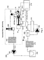
- FIG. 2 shows the apparatus 10 installed in a fuel filter assembly 100 which forms part of a fuel system 200 for an internal combustion engine.
- the illustrated fuel system 200 comprises a number of components making up a circuit.
- Fuel is drawn from a fuel tank 210 and passes through an inlet (port 1) of the fuel filter assembly 100 to the first inlet 20 of the control apparatus 10. Fuel leaving the apparatus 10 via the first outlet 40 is then drawn through a one way valve 220 and a primer pump 230 to a primary filter media 240. Fuel is then drawn out of the fuel filter assembly 100 through Port 2 and is drawn by a supply pump 250, is passed through a cooling plate 260 to the main filter 270. After the main filter 270, a pressure sensor 280 is provided to monitor the pressure in the fuel line.
- the fuel is then passed to a fuel control unit 290 which passes the fuel via a high pressure pump 300 to fuel injectors in a fuel rail or head gallery in an engine's cylinder head 310 and/or through a by-pass/overflow line from the fuel control unit 290 to the exit from the cylinder head 310 to be returned to the fuel filter assembly 100 via Port 3 to the second inlet 30 of the control apparatus 10.
- the control apparatus 10 determines the proportion of fuel to be re-circulated via outlet 40 and the proportion of fuel to be returned to the fuel tank 210 via outlet 50. Re-circulated fuel generally mixes with fuel from the fuel tank 210 when leaving the control apparatus 10 via outlet 40.
- Figure 2 illustrates an engine which is running relatively cold.
- the control apparatus 10 directs the majority of the relatively hot fuel received from the engine via inlet 30 back to the engine via outlet 40 with only a minority or none of the relatively hot fuel received from the engine via inlet 30 being returned to the fuel tank 210 via outlet 50.
- 90% of the relatively hot fuel received from the engine via inlet 30 is directed back to the engine via outlet 40 and the remaining 10% is returned to the fuel tank 210 via outlet 50.
- the variable valve in the control apparatus is arranged to be able to direct any proportion of fuel to the outlets 40, 50.
- the control apparatus 10 which may comprise a thermostatic return valve, is shown schematically in Figure 2 and includes a thermostatic bulb 11 which is arranged to vary the size of a passageway from second inlet 30 to first outlet 40 depending upon the temperature of fuel passed over the thermostatic bulb 11.
- the thermostatic bulb 11 has a pin 12 which is arranged to retract as shown in Figure 2 to pull a valve body 13 away from a valve seat 14 to open a passageway from the second inlet 30 to the first outlet 40 when the fuel is relatively cold. Conversely, when the fuel is warmer the pin 12 of the thermostatic bulb 11 extends to position the valve body 13 closer to or on the valve seat 14 to reduce the size of or close the passageway from the second inlet 30 to the first outlet 40.
- FIG. 3 Such a condition is shown in Figure 3 in which none of the relatively hot fuel received from the engine via inlet 30 is re-circulated back to the engine via first outlet 40 and 100% of the relatively hot fuel is returned to the fuel tank 210.
- the control apparatus 10 is arranged to be adjustable to direct any proportion of fuel to first outlet 40 or second outlet 50. This enables the temperature of fuel supplied to the engine to be controlled within specified limits.
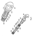
- Figure 6 shows an assembled and exploded view of an example of a valve which may be provided within the control apparatus 10 and Figure 7 shows a cross-section through the assembled valve.
- the valve comprises a thermal bulb 500 (equivalent to the thermostatic bulb 11 shown in Figures 2 to 5 ) housed and supported in a cartridge end cap 510.
- a spool 520 is inserted onto a thermal bulb pin and retained by return spring 530 in a housing of the fuel filter assembly 100.
- a seal 540 fits and seals onto a spool shaft by means of an inner lip and is retained by a spring 550 against a spool stop shoulder 560.
- the spool 520 with seal 540 retained by springs 530 and 550 can move inside the assembly of the cage 570 and cartridge end cap 510 depending upon the position of thermal bulb pin.
- the amount of relatively hot fuel returned back to the fuel tank 210 via the second outlet 50 ( Figures 1 to 5 ) is determined by the valve stroke distance between the sealing face of lip seal 580 and cage orifice 590 (see Figures 6 and 7 ).
- Thermal bulb 500 contains wax which expands and contracts depending upon the temperature of fuel. As the thermal bulb 500 expands due to a temperature increase, the thermal bulb pin 600 will extend and move spool 520 causing movement of seal 540 until it comes into contact with cage orifice 590. At this point the sealing contact between the sealing face 580 of lip seal 540 and the cage orifice 590 is reached. Sealing pressure is provided by the load of spring 550 and the compression of lip 610 over spool shaft 620.
- the second inlet 30 becomes sealed from the first outlet 40 (Port 2) and the first inlet 20 (Port 1) and all of the relatively hot re-circulated fuel from second inlet 30 (Port 3) is returned to the fuel tank 210 via second outlet 50 (Port 4).
- the valve is designed in such a way as to be able to accommodate further temperature expansion of the thermal bulb 500 and extension of the thermal bulb pin 600 and movement of spool 520.
- Figure 8 shows a partially cut-away perspective view of the outside of apparatus 10 and Figure 9 is another perspective view of the outside of apparatus 10 showing the inlets and outlets.
- FIGS 10a, 10b and 10c show the position of the variable valve within apparatus 10 at various fuel temperatures with the shut off valve disengaged.
- Figure 10a shows the apparatus 10 during cold running with fuel at less than +15°c.
- the valve is fully open with 90% of the relatively hot fuel received at the second inlet 30 (Port 3) returned to the engine via the first outlet 40 (Port 2) and the other 10% returned to the fuel tank via second outlet 50 (Port 4). Directing the majority of the relatively hot fuel back to the engine enables it to warm up more quickly enhancing its performance.
- Figure 10b shows the apparatus 10 during hot running with fuel between +15 and +30°c. In this condition a smaller proportion of relatively hot fuel received at the second inlet 30 (Port 3) is returned to the engine via the first outlet 40 (Port 2).
- Figure 10c shows the apparatus 10 during hot running with fuel above 30°c. In this condition all of the relatively hot fuel received at the second inlet 30 (Port 3) is returned to the fuel tank via the second outlet 50 (Port 4).
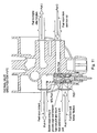
- FIG 11 shows a cross-section through the control apparatus 10 during cold running at below +15°c. In this condition there is a gap 700 for 90% of the fuel returning from the engine via inlet 30 (Port 3) to be returned to the engine via outlet 40 (Port 2). The remaining 10% of the fuel is returned to the fuel tank.
- Figure 12 shows the same cross-section as Figure 11 except with the fuel at more than +30°c.
- a valve body is in contact with a valve seat so that none of the fuel returning from the engine via inlet 30 (Port 30) is returned to the engine. Instead, it is all returned to the fuel tank.
- the shut off valve works by manually creating the same situation as with hot fuel.
- the handle of the shut off valve 60 is rotated and translated forward until it contacts the thermal bulb 500. This then forces a valve body into contact with a valve seat preventing fuel received from the engine via second inlet 30 (Port 3) from being re-circulated back to the engine via first outlet 40 (Port 2). Instead, all of the fuel from second inlet 30 (Port 3) is returned to the fuel tank.
- the apparatus 10 may include a temperature sensor to determine the temperature of the fuel and a control means such as a microprocessor to adjust the position of the valve and thus the proportion of the fuel directed to the first and second outlets dependent upon the measured temperature.
- a control means such as a microprocessor to adjust the position of the valve and thus the proportion of the fuel directed to the first and second outlets dependent upon the measured temperature.
- any suitable type of valve may be provided as either the variable valve or shut-off valve or both.
Landscapes
- Engineering & Computer Science (AREA)
- Chemical & Material Sciences (AREA)
- Combustion & Propulsion (AREA)
- Mechanical Engineering (AREA)
- General Engineering & Computer Science (AREA)
- Fuel-Injection Apparatus (AREA)
- Temperature-Responsive Valves (AREA)
- Output Control And Ontrol Of Special Type Engine (AREA)
Claims (18)
- Vorrichtung (10) zum Steuern der Temperatur von Brennstoff, der an einen Motor bereitgestellt wird, wobei die Vorrichtung aufweist:einen ersten Einlass (20) zum Aufnehmen von Brennstoff aus einem Brennstofftank,einen zweiten Einlass (30) zum Aufnehmen von Brennstoff, der von einem Motor zurückgegeben wird,einen ersten Auslass (40) zum Durchlassen von Brennstoff an einen Motor,einen zweiten Auslass (50) zum Durchlassen von Brennstoff an einen Brennstofftank und ein Ventil (13, 14) zum Leiten von Brennstoff, der von dem Motor zurückerhalten wurde über den zweiten Einlass (30) an einen oder beide der ersten (40) und zweiten (50) Auslässe, wobei das Ventil (13, 14) so betreibbar ist, dass es einen kontinuierlich einstellbaren Teil des von dem zweiten Einlass (30) aufgenommenen Brennstoffs zwischen den ersten (40) und zweiten (50) Auslässen aufteilt und wobei das Aufteilen des Flusses von den kombinierten Brennstofftemperaturen des Brennstoffs von den ersten (20) und zweiten (30) Einläsen gesteuert wird.
- Vorrichtung nach Anspruch 1, wobei das Ventil (13, 14) mehr des von dem zweiten Einlass (30) aufgenommenen Brennstoff an den ersten Auslass (40) leitet, wenn der Brennstoff unter einer vorbestimmten Temperatur liegt.
- Vorrichtung nach Anspruch 1 oder 2, wobei das Ventil (13, 14) weniger des von dem zweiten Einlass (30) erhaltenen Brennstoffs an den ersten Auslass (40) leitet, wenn der Brennstoff über einer vorbestimmten Temperatur liegt.
- Vorrichtung nach einem der vorhergehenden Ansprüche, darüber hinaus mit einem Absperrventil (60), um ein Einspritzen einer Brennstoffleitung zu ermöglichen durch Durchlassen des gesamten Brennstoffs und/oder von dem zweiten Einlass (30) aufgenommener Luft über den zweiten Auslass (50) an den Brennstofftank.
- Vorrichtung nach Anspruch 4, wobei das Absperrventil (60) so betreibbar ist, dass es den gesamten Brennstoff und/oder von dem zweiten Einlass (30) aufgenommene Luft über den zweiten Auslass (50) an den Brennstofftank durchlässt, unabhängig von der Position des einstellbaren Ventils (13, 14).
- Vorrichtung nach Anspruch 5, wobei das Absperrventil (60) so betreibbar ist, dass es das einstellbare Ventil (13, 14) so betätigt, dass der gesamte Brennstoff und/oder von dem zweiten Einlass (30) aufgenommene Luft über den zweiten Auslass (50) an den Brennstofftank durchgelassen wird unabhängig von der Position des einstellbaren Ventils (13, 14).
- Vorrichtung nach Anspruch 6, wobei ein Teil des Absperrventils (60) übersetzbar ist, um einen Ventilkörper (13) des einstellbaren Ventils in Kontakt mit einem Ventilsitz (14) des einstellbaren Ventils zu bringen.
- Vorrichtung nach einem der Ansprüche 4 bis 7, wobei das Absperrventil (60) manuell betreibbar ist.
- Vorrichtung nach einem der Ansprüche 4 bis 8, wobei das Absperrventil (60) nicht gestellt werden kann, wenn die Vorrichtung nicht in einer Einspritzstellung ist.
- Brennstofffilteranordnung mit der Vorrichtung nach einem der vorhergehenden Ansprüche.
- Brennkraftmaschine mit der Vorrichtung nach einem der Ansprüche 1 bis 9 oder der Brennstofffilteranordnung nach Anspruch 10.
- Verfahren zum Steuern der Temperatur von an einen Motor bereitgestelltem Brennstoff, wobei das Verfahren aufweist:Aufnehmen von Brennstoff aus einen Brennstofftank von einem ersten Einlass (20),Aufnehmen von von einem Motor zurückgegebenen Brennstoff von einem zweiten Einlass (30),Leiten von von einem Motor aufgenommenen Brennstoff an einen oder beide eines ersten Auslasses (40) zum Durchlassen von Brennstoff zurück in den Motor und eines zweiten Auslasses (50) zum Durchlassen von Brennstoff in einen Brennstofftank, wobei ein einstellbares Ventil (13, 14) verwendet wird, das so betreibbar ist, dass es einen kontinuierlich einstellbaren Teil des von dem zweiten Einlass (30) erhaltenen Brennstoffs zwischen den ersten (40) und den zweiten (50) Auslässen aufteilt und wobei der Teil des Flusses durch die kombinierten Brennstofftemperaturen des Brennstoffs von den ersten (20) und zweiten (30) Einlässen gesteuert wird.
- Verfahren nach Anspruch 12, wobei das Verfahren aufweist ein Verwenden eines Absperrventils (60), um ein Einspritzen einer Brennstoffleitung zu ermöglichen durch Durchlassen des gesamten Brennstoffs und/oder von dem zweiten Einlass (30) aufgenommener Luft an den Brennstofftank über den zweiten Auslass (50).
- Verfahren nach Anspruch 13, wobei das Absperrventil (60) den gesamten Brennstoff und/oder von dem zweiten Einlass (30) erhaltene Luft über den zweiten Auslass (50) an den Brennstofftank durchlässt unabhängig von der Position des einstellbaren Ventils (13, 14).
- Verfahren nach Anspruch 14 mit Verwenden des Absperrventils (60), um das einstellbare Ventil (13, 14) zu betätigen, so dass der gesamte Brennstoff und/oder von dem zweiten Einlass (30) aufgenommene Luft über den zweiten Auslass (50) an den Brennstofftank durchgelassen wird unabhängig von der Position des einstellbaren Ventils (13, 14).
- Verfahren nach Anspruch 15, wobei das Betätigen ein Übersetzen eines Teils des Absperrventils (60) umfasst, so dass ein Ventilkörper (13) des einstellbaren Ventils in Kontakt mit einem Ventilsitz (14) des einstellbaren Ventils gebracht wird.
- Verfahren nach einem der Ansprüche 12 bis 16 mit manuellem Betreiben des Absperrventils (60).
- Verfahren nach einem der Ansprüche 12 bis 17 mit Stellen des Absperrventils (60) nur wenn die Vorrichtung in einer Einspritzstellung ist.
Applications Claiming Priority (1)
| Application Number | Priority Date | Filing Date | Title |
|---|---|---|---|
| GB0606777A GB2436854B (en) | 2006-04-03 | 2006-04-03 | Apparatus for controlling the temperature of fuel supplied to an engine |
Publications (3)
| Publication Number | Publication Date |
|---|---|
| EP1843036A2 EP1843036A2 (de) | 2007-10-10 |
| EP1843036A3 EP1843036A3 (de) | 2009-04-08 |
| EP1843036B1 true EP1843036B1 (de) | 2011-06-08 |
Family
ID=36425232
Family Applications (1)
| Application Number | Title | Priority Date | Filing Date |
|---|---|---|---|
| EP20070251459 Active EP1843036B1 (de) | 2006-04-03 | 2007-04-02 | Vorrichtung zur Regelung der Temperatur des einer Brennkraftmaschine zugeführten Kraftstoffs |
Country Status (2)
| Country | Link |
|---|---|
| EP (1) | EP1843036B1 (de) |
| GB (1) | GB2436854B (de) |
Cited By (2)
| Publication number | Priority date | Publication date | Assignee | Title |
|---|---|---|---|---|
| RU2606544C2 (ru) * | 2012-06-27 | 2017-01-10 | Камминз Филтрэйшн Айпи, Инк. | Термостатический рециркуляционный клапан для модуля фильтрации топлива |
| US10927801B2 (en) | 2017-11-29 | 2021-02-23 | Mann+Hummel Gmbh | Valve device and fuel filter module |
Families Citing this family (4)
| Publication number | Priority date | Publication date | Assignee | Title |
|---|---|---|---|---|
| JP4347271B2 (ja) * | 2005-07-06 | 2009-10-21 | 京三電機株式会社 | リターン環流バルブ |
| JP4488069B2 (ja) * | 2007-12-27 | 2010-06-23 | 株式会社デンソー | 燃料供給装置 |
| CN103174563A (zh) * | 2013-02-06 | 2013-06-26 | 于淼 | 用于柴油发动机的节能供油方法及其供油系统 |
| CN109184975B (zh) * | 2018-10-31 | 2024-03-22 | 东风富士汤姆森调温器有限公司 | 一种燃油温控阀及车辆燃油温控系统 |
Family Cites Families (9)
| Publication number | Priority date | Publication date | Assignee | Title |
|---|---|---|---|---|
| US4502450A (en) * | 1979-07-13 | 1985-03-05 | Standard-Thomson Corporation | Diesel fuel control valve and system |
| US4502451A (en) * | 1982-08-25 | 1985-03-05 | Standard-Thomson Corporation | Diesel fuel control apparatus and system |
| US4617116A (en) * | 1984-05-04 | 1986-10-14 | Ford Motor Company | Automotive type fuel feed system |
| DE3427396A1 (de) * | 1984-07-25 | 1986-01-30 | Helphos Gmbh, 3388 Bad Harzburg | Vorrichtung zum einbau in die zufuehrungs- und rueckfuehrungsleitung des kraftstoffes zu bzw. von dieselmotoren |
| GB2259587A (en) * | 1991-09-11 | 1993-03-17 | Ford Motor Co | Engine fuel supply |
| DE19628591A1 (de) * | 1996-07-16 | 1998-01-22 | Knecht Filterwerke Gmbh | 3/2-Wegeventil für eine Kraftstoffversorgungseinrichtung eines Einspritz-Verbrennungsmotors |
| US5887572A (en) * | 1997-05-05 | 1999-03-30 | Ford Global Technologies, Inc. | Pressure and temperature control for fuel delivery systems |
| WO2001038718A1 (en) * | 1999-11-24 | 2001-05-31 | Parker-Hannifin Corporation | Air eliminating return fuel recirculation valve |
| JP4399697B2 (ja) * | 2001-02-28 | 2010-01-20 | 株式会社デンソー | 燃料供給装置および燃料濾過装置 |
-
2006
- 2006-04-03 GB GB0606777A patent/GB2436854B/en active Active
-
2007
- 2007-04-02 EP EP20070251459 patent/EP1843036B1/de active Active
Cited By (2)
| Publication number | Priority date | Publication date | Assignee | Title |
|---|---|---|---|---|
| RU2606544C2 (ru) * | 2012-06-27 | 2017-01-10 | Камминз Филтрэйшн Айпи, Инк. | Термостатический рециркуляционный клапан для модуля фильтрации топлива |
| US10927801B2 (en) | 2017-11-29 | 2021-02-23 | Mann+Hummel Gmbh | Valve device and fuel filter module |
Also Published As
| Publication number | Publication date |
|---|---|
| EP1843036A2 (de) | 2007-10-10 |
| GB2436854A (en) | 2007-10-10 |
| GB0606777D0 (en) | 2006-05-10 |
| GB2436854B (en) | 2010-12-22 |
| EP1843036A3 (de) | 2009-04-08 |
Similar Documents
| Publication | Publication Date | Title |
|---|---|---|
| EP1843036B1 (de) | Vorrichtung zur Regelung der Temperatur des einer Brennkraftmaschine zugeführten Kraftstoffs | |
| EP2864607B1 (de) | Flüssigkeitsmengenregler | |
| RU2535828C2 (ru) | Дополнительная система отопления транспортного средства | |
| US7721973B2 (en) | Valve | |
| US7845574B2 (en) | Cartridge for a mixer faucet, faucet comprising a cartridge of this type, and thermostatic assembly to be fitted together with this cartridge | |
| US5979778A (en) | Thermostatic valve arrangement | |
| US20100213010A1 (en) | Automatic Shut-Off Valve For The Oil Circuit In An Airplane Engine | |
| US5934552A (en) | Thermally responsive valve assembly | |
| EP1234111B1 (de) | Kraftstoffrückführventil mit entlüftung | |
| JP4608539B2 (ja) | クーラントによって冷却される内燃機関用のクーラント回路 | |
| US20090205589A1 (en) | Thermostatic Valve | |
| GB2401167A (en) | Engine cooling system | |
| JP2007107522A (ja) | 燃焼機関の冷却システム | |
| GB2401166A (en) | Temperature responsive flow control valves for IC engines | |
| KR20190005967A (ko) | 통합형 화상 방지 디바이스를 구비한 수도꼭지 조립체 | |
| EP2045687B1 (de) | Mischbatteriesystem für ein Flugzeug | |
| WO2002033500A1 (en) | Thermostatic mixing valve | |
| US9394824B2 (en) | Cooling system for a combustion engine | |
| US7669830B2 (en) | Three position shutoff valve | |
| US6000421A (en) | Valve device for a heat exchanger located in a bypass in a cooling circuit, especially of an internal combustion engine | |
| US5787845A (en) | Combined bypass and thermostat assembly | |
| US20060081222A1 (en) | Method to control starter / generator cooling fuel flow during engine starting | |
| WO2008095953A1 (en) | Valve | |
| US7051692B1 (en) | Starting system for a marine engine | |
| US6766637B2 (en) | Battle override valve |
Legal Events
| Date | Code | Title | Description |
|---|---|---|---|
| PUAI | Public reference made under article 153(3) epc to a published international application that has entered the european phase |
Free format text: ORIGINAL CODE: 0009012 |
|
| AK | Designated contracting states |
Kind code of ref document: A2 Designated state(s): AT BE BG CH CY CZ DE DK EE ES FI FR GB GR HU IE IS IT LI LT LU LV MC MT NL PL PT RO SE SI SK TR |
|
| AX | Request for extension of the european patent |
Extension state: AL BA HR MK YU |
|
| PUAL | Search report despatched |
Free format text: ORIGINAL CODE: 0009013 |
|
| AK | Designated contracting states |
Kind code of ref document: A3 Designated state(s): AT BE BG CH CY CZ DE DK EE ES FI FR GB GR HU IE IS IT LI LT LU LV MC MT NL PL PT RO SE SI SK TR |
|
| AX | Request for extension of the european patent |
Extension state: AL BA HR MK RS |
|
| 17P | Request for examination filed |
Effective date: 20091007 |
|
| 17Q | First examination report despatched |
Effective date: 20091102 |
|
| AKX | Designation fees paid |
Designated state(s): DE FR IT SE |
|
| GRAP | Despatch of communication of intention to grant a patent |
Free format text: ORIGINAL CODE: EPIDOSNIGR1 |
|
| GRAC | Information related to communication of intention to grant a patent modified |
Free format text: ORIGINAL CODE: EPIDOSCIGR1 |
|
| GRAS | Grant fee paid |
Free format text: ORIGINAL CODE: EPIDOSNIGR3 |
|
| GRAA | (expected) grant |
Free format text: ORIGINAL CODE: 0009210 |
|
| AK | Designated contracting states |
Kind code of ref document: B1 Designated state(s): DE FR IT SE |
|
| REG | Reference to a national code |
Ref country code: DE Ref legal event code: R096 Ref document number: 602007015012 Country of ref document: DE Effective date: 20110721 |
|
| PG25 | Lapsed in a contracting state [announced via postgrant information from national office to epo] |
Ref country code: SE Free format text: LAPSE BECAUSE OF FAILURE TO SUBMIT A TRANSLATION OF THE DESCRIPTION OR TO PAY THE FEE WITHIN THE PRESCRIBED TIME-LIMIT Effective date: 20110608 |
|
| PLBE | No opposition filed within time limit |
Free format text: ORIGINAL CODE: 0009261 |
|
| STAA | Information on the status of an ep patent application or granted ep patent |
Free format text: STATUS: NO OPPOSITION FILED WITHIN TIME LIMIT |
|
| 26N | No opposition filed |
Effective date: 20120309 |
|
| PG25 | Lapsed in a contracting state [announced via postgrant information from national office to epo] |
Ref country code: IT Free format text: LAPSE BECAUSE OF FAILURE TO SUBMIT A TRANSLATION OF THE DESCRIPTION OR TO PAY THE FEE WITHIN THE PRESCRIBED TIME-LIMIT Effective date: 20110608 |
|
| REG | Reference to a national code |
Ref country code: DE Ref legal event code: R097 Ref document number: 602007015012 Country of ref document: DE Effective date: 20120309 |
|
| REG | Reference to a national code |
Ref country code: FR Ref legal event code: PLFP Year of fee payment: 9 |
|
| REG | Reference to a national code |
Ref country code: FR Ref legal event code: PLFP Year of fee payment: 10 |
|
| REG | Reference to a national code |
Ref country code: FR Ref legal event code: PLFP Year of fee payment: 11 |
|
| REG | Reference to a national code |
Ref country code: FR Ref legal event code: PLFP Year of fee payment: 12 |
|
| REG | Reference to a national code |
Ref country code: DE Ref legal event code: R081 Ref document number: 602007015012 Country of ref document: DE Owner name: PARKER HANNIFIN MANUFACTURING LIMITED, HEMEL H, GB Free format text: FORMER OWNER: PARKER HANNIFIN (UK) LTD., DEWSBURY, GB |
|
| PGFP | Annual fee paid to national office [announced via postgrant information from national office to epo] |
Ref country code: FR Payment date: 20230425 Year of fee payment: 17 Ref country code: DE Payment date: 20230427 Year of fee payment: 17 |