EP1843020A2 - Slippage prevention mechanism for toothed torque transmission member - Google Patents
Slippage prevention mechanism for toothed torque transmission member Download PDFInfo
- Publication number
- EP1843020A2 EP1843020A2 EP07007346A EP07007346A EP1843020A2 EP 1843020 A2 EP1843020 A2 EP 1843020A2 EP 07007346 A EP07007346 A EP 07007346A EP 07007346 A EP07007346 A EP 07007346A EP 1843020 A2 EP1843020 A2 EP 1843020A2
- Authority
- EP
- European Patent Office
- Prior art keywords
- sprocket
- slippage prevention
- prevention mechanism
- transmission member
- cylinder block
- Prior art date
- Legal status (The legal status is an assumption and is not a legal conclusion. Google has not performed a legal analysis and makes no representation as to the accuracy of the status listed.)
- Granted
Links
- 230000002265 prevention Effects 0.000 title claims abstract description 50
- 230000005540 biological transmission Effects 0.000 title claims description 12
- 238000002485 combustion reaction Methods 0.000 claims abstract description 23
- 230000000149 penetrating effect Effects 0.000 claims description 3
- 239000000314 lubricant Substances 0.000 description 3
- 230000001105 regulatory effect Effects 0.000 description 2
- 238000011144 upstream manufacturing Methods 0.000 description 2
- 238000010276 construction Methods 0.000 description 1
- 238000006073 displacement reaction Methods 0.000 description 1
- 230000002452 interceptive effect Effects 0.000 description 1
- 238000012423 maintenance Methods 0.000 description 1
- 238000012986 modification Methods 0.000 description 1
- 230000004048 modification Effects 0.000 description 1
- 230000035515 penetration Effects 0.000 description 1
Images


Classifications
-
- F—MECHANICAL ENGINEERING; LIGHTING; HEATING; WEAPONS; BLASTING
- F16—ENGINEERING ELEMENTS AND UNITS; GENERAL MEASURES FOR PRODUCING AND MAINTAINING EFFECTIVE FUNCTIONING OF MACHINES OR INSTALLATIONS; THERMAL INSULATION IN GENERAL
- F16H—GEARING
- F16H7/00—Gearings for conveying rotary motion by endless flexible members
- F16H7/08—Means for varying tension of belts, ropes, or chains
-
- F—MECHANICAL ENGINEERING; LIGHTING; HEATING; WEAPONS; BLASTING
- F01—MACHINES OR ENGINES IN GENERAL; ENGINE PLANTS IN GENERAL; STEAM ENGINES
- F01L—CYCLICALLY OPERATING VALVES FOR MACHINES OR ENGINES
- F01L1/00—Valve-gear or valve arrangements, e.g. lift-valve gear
- F01L1/02—Valve drive
-
- F—MECHANICAL ENGINEERING; LIGHTING; HEATING; WEAPONS; BLASTING
- F01—MACHINES OR ENGINES IN GENERAL; ENGINE PLANTS IN GENERAL; STEAM ENGINES
- F01L—CYCLICALLY OPERATING VALVES FOR MACHINES OR ENGINES
- F01L1/00—Valve-gear or valve arrangements, e.g. lift-valve gear
- F01L1/02—Valve drive
- F01L1/022—Chain drive
-
- F—MECHANICAL ENGINEERING; LIGHTING; HEATING; WEAPONS; BLASTING
- F01—MACHINES OR ENGINES IN GENERAL; ENGINE PLANTS IN GENERAL; STEAM ENGINES
- F01L—CYCLICALLY OPERATING VALVES FOR MACHINES OR ENGINES
- F01L1/00—Valve-gear or valve arrangements, e.g. lift-valve gear
- F01L1/02—Valve drive
- F01L1/024—Belt drive
-
- F—MECHANICAL ENGINEERING; LIGHTING; HEATING; WEAPONS; BLASTING
- F16—ENGINEERING ELEMENTS AND UNITS; GENERAL MEASURES FOR PRODUCING AND MAINTAINING EFFECTIVE FUNCTIONING OF MACHINES OR INSTALLATIONS; THERMAL INSULATION IN GENERAL
- F16H—GEARING
- F16H7/00—Gearings for conveying rotary motion by endless flexible members
- F16H7/18—Means for guiding or supporting belts, ropes, or chains
-
- F—MECHANICAL ENGINEERING; LIGHTING; HEATING; WEAPONS; BLASTING
- F16—ENGINEERING ELEMENTS AND UNITS; GENERAL MEASURES FOR PRODUCING AND MAINTAINING EFFECTIVE FUNCTIONING OF MACHINES OR INSTALLATIONS; THERMAL INSULATION IN GENERAL
- F16H—GEARING
- F16H7/00—Gearings for conveying rotary motion by endless flexible members
- F16H7/08—Means for varying tension of belts, ropes, or chains
- F16H2007/0802—Actuators for final output members
- F16H2007/081—Torsion springs
Definitions
- This invention relates to the prevention of slippage of a timing chain or toothed timing belt in an internal combustion engine.
- JPH 10-246297A published by Japan Patent Office in 1998, discloses a timing chain drive device provided with a slippage prevention rail.
- the timing chain is looped around the drive sprocket, a driven sprocket fixed onto a cam shaft for an intake valve, and a driven sprocket fixed onto a cam shaft for an exhaust valve.
- the slippage prevention rail is disposed in a position on the outside of an engaging part between the timing chain and the drive sprocket so as to prevent the timing chain from displacing radially outward.
- the sprockets and the timing chain are disposed on the outside of a cylinder block and a cylinder head of the internal combustion engine, and enclosed in a chain case fitted to the cylinder block.
- the timing chain drive device comprises a tension rail on a downstream side of the drive sprocket with respect to the travel direction of the timing chain.
- the tension rail is designed to provide the timing chain with a tensile force by pressing the timing chain inward as well as to guide the travel of the timing chain.
- the timing chain drive device also comprises a fixed guide located on the upstream side of the drive sprocket with respect to the travel direction of the timing chain for guiding the travel of the timing chain.
- the slippage prevention rail is constructed to project toward the cylinder block from the chain case, and has a sufficient width to cover substantially the entire width of the timing chain.
- the slippage prevention rail prevents lubricant from scattering from the engaging part between the timing chain and the drive sprocket, and ensures a supply of lubricant to the friction surface between the tension rail and the timing chain, thereby preventing wear of the tension rail and extensional deformation of the timing chain.
- the slippage prevention rail projecting toward the cylinder block from the chain case may interfere with the auxiliary sprocket or the signal plate when the chain case is fitted to the cylinder block.
- the slippage prevention rail may also interfere with the auxiliary sprocket or the signal plate when the chain case is removed from the cylinder block or fitted to the cylinder block again, during maintenance of the timing chain in the chain case.
- this invention provides a slippage prevention mechanism for a toothed endless torque transmission member which is looped around a sprocket fixed onto a crank shaft of an internal combustion engine on the outside of a cylinder block.
- the slippage prevention mechanism comprises a base portion fixed to the cylinder block on the outside of the cylinder block, an arm extending from the base portion in a perpendicular direction to the crank shaft, and a slippage prevention rail formed on the arm to prevent slippage of the toothed endless torque transmission member with respect to the sprocket.
- FIG. 1 is a front view of an internal combustion engine including a slippage prevention mechanism for a timing chain according to this invention in a state where a chain case and a signal plate are removed.
- FIG. 2 is a side view of the slippage prevention mechanism.
- FIG. 3 is a side view of essential parts of the internal combustion engine in a state where the chain case is removed.
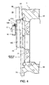
- FIG. 4 is a bottom view of the slippage prevention mechanism seen along the direction IV-IV in FIG. 2.
- FIG. 5 is a rear view of the slippage prevention mechanism seen along the direction V-V in FIG. 3.
- FIG. 6 is a front view of the slippage prevention mechanism.
- FIG. 7 is a side view of the slippage prevention mechanism.
- FIG. 8 is a plan view of the slippage prevention mechanism.
- FIG. 9 is a front view of the slippage prevention mechanism including a chain tensioner.
- a V-shaped internal combustion engine 100 for a vehicle comprises two cylinder heads 4A, 4B and a common cylinder block 1.
- a crank shaft 2 of the internal combustion engine 100 projects to the outside of the cylinder block 1.
- two drive sprockets 3A and 3B are fixed onto the crank shaft 2 on the outside of the cylinder block 1.
- an intake cam shaft 5 of intake cams for opening and closing intake valves and an exhaust cam shaft 6 of exhaust cams for opening and closing exhaust valves project to the outside of the cylinder heads 4A and 4B.
- a driven sprocket 5A is fixed onto a projecting end of the intake cam shaft 5, and a driven sprocket 6A is fixed onto a projecting end of the exhaust cam shaft 6.
- a timing chain 7A is looped around these sprockets 3A, 5A, and 6A.
- a timing chain 7B is looped around these sprockets 3B, 5A, and 6A.
- timing chains 7A and 7B also travel clockwise.
- Fixed rails 8A for guiding the timing chains 7A and 7B, respectively, are both disposed on the upstream side of the drive sprockets 3A and 3B with respect to the travel direction of the timing chains 7A and 7B,
- Movable tension rails 8B which respectively press the timing chains 7A and 7B inward using resilient forces generated respectively by chain tensioners 9 are disposed on the downstream side of the drive sprockets 3A and 3B with respect to travel direction of the timing chains 7A and 7B.
- the movable tension rails 8A and 8B are kept in a state of constant contact with the timing chains 7A and 7B respectively.
- a slippage prevention mechanism 10 is provided underneath the drive sprocket 3A and 3B for preventing slippage of the timing chains 7A and 7B.
- a base portion 10A of the slippage prevention mechanism 10 is fixed to a skirt 1A forming a lowermost portion of the cylinder block 1, which is connected to an oil pan 11.
- the slippage prevention mechanism 10 comprises an arm 10C extending from the base portion 10A in a perpendicular direction to the crank shaft 2 and intersects therewith in an offset position.
- An arc-shaped recess 10B facing upward is formed on a tip of the arm 10C as a slippage prevention rail.
- the arc-shaped recess 10B faces the timing chain 7A engaged with the drive sprocket 3A and the timing chain 7B engaged with the drive sprocket 3B from beneath with a predetermined clearance therebetween.
- the predetermined clearance is set within a displacement range of the timing chain 7A (7B) in the radial direction within which the engagement between the timing chain 7A(7B) and the drive sprocket 3A(3B) is maintained. Specifically, this condition is satisfied by setting the predetermined clearance smaller than the height of a tooth of the drive sprocket 3A(3B).
- the width of the arc-shaped recess 10B is set to be equal to the distance from a side surface facing the internal combustion engine 100 on the timing chain 7A engaged with the drive sprocket 3A to a side surface separated from the internal combustion engine 100 on the timing chain 7B engaged with the drive sprocket 3B.
- the length of the arc-shaped recess 10B in the circumferential direction is set to a value that can cover both an engaging part between the timing chain 7A and the drive sprocket 3A and an engaging part between the timing chain 7B and the drive sprocket 3B. According to this setting of the size of arc-shaped recess 10B, the scattering of lubricant from the engaging part between the timing chain 7A (7B) and the drive sprocket 3A(3B) is prevented without failure.
- the drive sprockets 3A and 3B, the driven sprockets 5A and 6A, the timing chains 7A and 7B, the fixed rails 8A, the tension rails 8B, the chain tensioners 9, and the slippage prevention mechanism 10 described above form a timing chain drive device.
- crank shaft 2 penetrates the drive sprockets 3A and 3B.
- a pump drive sprocket 12 serving as an auxiliary sprocket for driving an oil pump and a signal plate 19 for detecting an angular position of the internal combustion engine 100 are fixed onto a penetrating end of the crank shaft 2.
- the internal combustion engine 100 is mounted on a vehicle in a position to cause the signal plate 19 to face the forward direction of the vehicle.
- a driven sprocket 14 is fixed onto a pump shaft 13 of the oil pump.
- a chain 15 is looped around the pump drive sprocket 12 and the driven sprocket 14 as an auxiliary endless torque transmission member.
- a chain tensioner 16 for pressing the chain 15 inward to remove slackness therein is provided on the downstream side of the pump drive sprocket 12 with respect to the rotation direction of the pump drive sprocket 12.
- the chain tensioner 16 is supported so as to swing about a pin 17 fixed to a central part of the arm 10C of the slippage prevention mechanism 10.
- the chain tensioner 16 comprises an arc-shaped pressing surface contacting the outer circumferential surface of the chain 15.
- a torsion coil spring 18 an end of which is supported by a bolt 18A projecting from the arm 10C in the separating direction from the cylinder block 1 exerts a rotational force on the chain tensioner 16 as shown by the arrow in the figure. According to this rotational force, the chain tensioner 16 pushes the chain 15 inward as shown in FIG. 3.
- the timing chain drive device and the oil pump drive device are enclosed in a chain enclosing space 20 which is formed by a wall surface 21 and the chain case fitted thereto.
- the wall surface 21 corresponds to the outer surface of the cylinder block 1 and the cylinder heads 4A, 4B of the internal combustion engine 100 facing the forward direction of the vehicle.
- the internal combustion engine 100 comprises a joint surface 22 projecting from the wall surface 21 such that the chain case is jointed thereto.
- a part of the timing chain drive device and oil pump drive device is located in the recessed area surrounded by the joint surface 22.
- a joint surface 23 is formed on the lower end of the skirt 1A so as to connect to the oil pan 11.
- the signal plate 19 is further fixed onto the crank shaft 2 in front of the pump drive sprocket 12.
- the crank shaft 2 penetrates the chain case and a pulley for driving a further other equipment is fixed onto the penetration end on the outside of the chain case.
- the drive sprocket 3A Since the drive sprocket 3A is disposed near to the wall surface 21, its side face facing the wall surface 21 is located in the recessed area surrounded by the joint surface 22. Accordingly, a part of the drive sprocket 3A and the timing chain 7A is disposed in the recessed area, and the other part of the drive sprocket 3A and the timing chain 7A projects from the joint surface 22 in the forward direction of the vehicle or in the separating direction from the cylinder block 1.
- a pair of attachment holes comprising a round hole 31 and an elongated hole 32 are formed through the base portion 10A of the slippage prevention mechanism 10.
- the length of the short axis of the elongated hole 32 is equal to the diameter of the round hole 31, and the round hole 31 is located on the extension of the long axis of the elongated hole 32.
- a boss part 10D is formed on the central portion of the arm 10C so as to fix the pin 17.
- the boss part 10D projects in the forward direction of the vehicle.
- the side face of the arm 10C facing the forward direction of the vehicle is located in an advanced position in the forward direction of the vehicle with respect to the joint surface 22 and a fixing surface of the base portion 10A fixed to the skirt 1A.
- the boss part 10D projects further in the forward direction of the vehicle from the side face of the arm 10C facing the forward direction of the vehicle.
- the width of the arc-shaped recess 10B is set equal to the width of the space occupied by the drive sprockets 3A and 3B. According to the above configurations, the arm 10C and the chain tensioner 16 of the slippage prevention mechanism 10 are offset from each other along the axial direction of the crank shaft 2.
- the torsion coil spring 18 applies a resilient force to the chain tensioner 16 in the clockwise direction in FIG. 7.
- the base portion 10A of the slippage prevention mechanism 10 is fixed to the fixing surface of the skirt 1A by reamer bolts 33.
- the fixing surface forms a substantially common vertical surface with the joint surface 22.
- a pair of screw holes are alined vertically.
- the reamer bolts 33 are screwed into the screw holes in a state where the round hole 31 and the elongated hole 32 of the base portion 10A are placed on the screw holes.
- the screw holes formed on the fixing surface of the skirt 1A have a circular cross-section with a diameter equal to the diameter of the round hole 31 or the length of the short axis of the elongated hole 32.
- the elongated hole 32 as one of the attachment holes provided in the base portion 10A, a tolerance to dimensional error in the distance between the pair of screw holes can be ensured.
- the arm 10C expands to both sides of the joint surface 22 as shown in FIGs. 4 and 6.
- the drive sprocket 3A and the timing chain 7A also expand to both sides of the joint surface 22.
- the chain tensioner 16 is located in the same position as the chain 15 in the direction along the crank shaft 2 as shown in FIG. 5.
- the slippage prevention mechanism 10 thus constructed comprises the base portion 10A fixed to the skirt 1A of the cylinder block 1, and the arm 10C extending from the base portion 10A to a position underneath the drive sprockets 3A, 3B fixed respectively to the crank shaft 2.
- the slippage prevention mechanism 10 does not interfere with the pump drive sprocket 12 and the signal plate 19.
- the base portion 10A fixed directly to the skirt 1A of the cylinder block 1 can maintain the clearance between the timing chains 7A, 7B and the arc-shaped recess 10B more precisely than in the case where the slippage prevention rail is fixed to the chain case.
- the chain tensioner 16 is supported by a pin 17 projecting from the boss part 10D of the arm 10 in the forward direction of the vehicle, the chain tensioner 16 is supported in an offset position from the slippage prevention rail in the forward direction of the vehicle.
- the chain tensioner 16 therefore does not interfere with the slippage prevention rail.
- supporting the chain tensioner 16 by the slippage prevention mechanism 10 facilitates layout of the members of the oil pump drive device.
- Tokugan 2006-106006 The contents of Tokugan 2006-106006 , with a filing date of April 7, 2006 in Japan, are hereby incorporated by reference.
- the drive sprockets 3A, 3B, the pump drive sprocket 12, and the signal plate 19 are aligned in this order on the crank shaft 2 from the wall surface 21 of the cylinder block 1 towards the vehicle front.
- this invention is also applicable to an internal combustion engine in which the pump drive sprocket 12, drive sprockets 3A, 3B, and signal plate 19 are aligned in this order on the crank shaft 2 from the wall surface 21 towards the vehicle front.
- This invention is also applicable to an internal combustion engine in which the signal plate 19, drive sprockets 3A, 3B, and pump drive sprocket 12 are aligned in this order on the crank shaft 2 from the wall surface 21 towards the vehicle front.
- this invention can be implemented by simply modifying the relationship of the locations of the arm 10C and the chain tensioner 16 with respect to the wall surface 21 in the direction along the crank shaft 2.
- the toothed endless torque transmission member in the title is a generic expression including a timing chain and a toothed timing belt.
- the chain 15 whose tensile force is regulated by the chain tensioner 16 is a chain for driving an oil pump, but the chain tensioner 16 may be used for regulating the tensile force of a chain for driving different auxiliary equipment. It is also possible to replace the chain 15 with a belt and the chain tensioner 16 with a belt tensioner.
Landscapes
- Engineering & Computer Science (AREA)
- General Engineering & Computer Science (AREA)
- Mechanical Engineering (AREA)
- Devices For Conveying Motion By Means Of Endless Flexible Members (AREA)
- Gears, Cams (AREA)
Abstract
Description
- This invention relates to the prevention of slippage of a timing chain or toothed timing belt in an internal combustion engine.
- In order to prevent a timing chain from slipping on a drive sprocket fixed onto a crank shaft of an internal combustion engine,
JPH 10-246297A - The timing chain is looped around the drive sprocket, a driven sprocket fixed onto a cam shaft for an intake valve, and a driven sprocket fixed onto a cam shaft for an exhaust valve.
- The slippage prevention rail is disposed in a position on the outside of an engaging part between the timing chain and the drive sprocket so as to prevent the timing chain from displacing radially outward.
- The sprockets and the timing chain are disposed on the outside of a cylinder block and a cylinder head of the internal combustion engine, and enclosed in a chain case fitted to the cylinder block.
- The timing chain drive device comprises a tension rail on a downstream side of the drive sprocket with respect to the travel direction of the timing chain. The tension rail is designed to provide the timing chain with a tensile force by pressing the timing chain inward as well as to guide the travel of the timing chain. The timing chain drive device also comprises a fixed guide located on the upstream side of the drive sprocket with respect to the travel direction of the timing chain for guiding the travel of the timing chain.
- The slippage prevention rail is constructed to project toward the cylinder block from the chain case, and has a sufficient width to cover substantially the entire width of the timing chain. The slippage prevention rail prevents lubricant from scattering from the engaging part between the timing chain and the drive sprocket, and ensures a supply of lubricant to the friction surface between the tension rail and the timing chain, thereby preventing wear of the tension rail and extensional deformation of the timing chain.
- In an internal combustion engine in which an auxiliary sprocket for driving an oil pump or a signal plate for measuring an angular position of the internal combustion engine is fixed onto the crank shaft between the drive sprocket and the chain case, the slippage prevention rail projecting toward the cylinder block from the chain case may interfere with the auxiliary sprocket or the signal plate when the chain case is fitted to the cylinder block.
- The slippage prevention rail may also interfere with the auxiliary sprocket or the signal plate when the chain case is removed from the cylinder block or fitted to the cylinder block again, during maintenance of the timing chain in the chain case.
- It is therefore an object of this invention to prevent a slippage prevention rail from interfering with the other members in the chain case.
- In order to achieve the above object, this invention provides a slippage prevention mechanism for a toothed endless torque transmission member which is looped around a sprocket fixed onto a crank shaft of an internal combustion engine on the outside of a cylinder block.
- The slippage prevention mechanism comprises a base portion fixed to the cylinder block on the outside of the cylinder block, an arm extending from the base portion in a perpendicular direction to the crank shaft, and a slippage prevention rail formed on the arm to prevent slippage of the toothed endless torque transmission member with respect to the sprocket.
- The details as well as other features and advantages of this invention are set forth in the remainder of the specification and are shown in the accompanying drawings.
- FIG. 1 is a front view of an internal combustion engine including a slippage prevention mechanism for a timing chain according to this invention in a state where a chain case and a signal plate are removed.
- FIG. 2 is a side view of the slippage prevention mechanism.
- FIG. 3 is a side view of essential parts of the internal combustion engine in a state where the chain case is removed.
- FIG. 4 is a bottom view of the slippage prevention mechanism seen along the direction IV-IV in FIG. 2.
- FIG. 5 is a rear view of the slippage prevention mechanism seen along the direction V-V in FIG. 3.
- FIG. 6 is a front view of the slippage prevention mechanism.
- FIG. 7 is a side view of the slippage prevention mechanism.
- FIG. 8 is a plan view of the slippage prevention mechanism.
- FIG. 9 is a front view of the slippage prevention mechanism including a chain tensioner.
- Referring to FIG. 1 of the drawings, a V-shaped
internal combustion engine 100 for a vehicle comprises twocylinder heads common cylinder block 1. Acrank shaft 2 of theinternal combustion engine 100 projects to the outside of thecylinder block 1. - Referring to FIG. 6, two
drive sprockets crank shaft 2 on the outside of thecylinder block 1. - Referring again to FIG. 1, an
intake cam shaft 5 of intake cams for opening and closing intake valves and an exhaust cam shaft 6 of exhaust cams for opening and closing exhaust valves project to the outside of thecylinder heads sprocket 5A is fixed onto a projecting end of theintake cam shaft 5, and a drivensprocket 6A is fixed onto a projecting end of the exhaust cam shaft 6. - In order to transfer the rotation of the
drive sprocket 3A to the drivensprocket 5A and the drivensprocket 6A of thecylinder head 4A, atiming chain 7A is looped around thesesprockets - In order to transfer the rotation of the
drive sprocket 3B to the drivensprocket 5A and the drivensprocket 6A of thecylinder head 4B, atiming chain 7B is looped around thesesprockets - Assuming that all the
sprockets timing chains rails 8A for guiding thetiming chains drive sprockets timing chains -
Movable tension rails 8B which respectively press thetiming chains chain tensioners 9 are disposed on the downstream side of thedrive sprockets timing chains movable tension rails timing chains - A
slippage prevention mechanism 10 is provided underneath thedrive sprocket timing chains base portion 10A of theslippage prevention mechanism 10 is fixed to askirt 1A forming a lowermost portion of thecylinder block 1, which is connected to anoil pan 11. Theslippage prevention mechanism 10 comprises anarm 10C extending from thebase portion 10A in a perpendicular direction to thecrank shaft 2 and intersects therewith in an offset position. - An arc-
shaped recess 10B facing upward is formed on a tip of thearm 10C as a slippage prevention rail. The arc-shaped recess 10B faces thetiming chain 7A engaged with thedrive sprocket 3A and thetiming chain 7B engaged with thedrive sprocket 3B from beneath with a predetermined clearance therebetween. - Herein, the predetermined clearance is set within a displacement range of the
timing chain 7A (7B) in the radial direction within which the engagement between thetiming chain 7A(7B) and thedrive sprocket 3A(3B) is maintained. Specifically, this condition is satisfied by setting the predetermined clearance smaller than the height of a tooth of thedrive sprocket 3A(3B). - Referring again to FIG. 6, the width of the arc-
shaped recess 10B is set to be equal to the distance from a side surface facing theinternal combustion engine 100 on thetiming chain 7A engaged with thedrive sprocket 3A to a side surface separated from theinternal combustion engine 100 on thetiming chain 7B engaged with thedrive sprocket 3B. The length of the arc-shaped recess 10B in the circumferential direction is set to a value that can cover both an engaging part between thetiming chain 7A and thedrive sprocket 3A and an engaging part between thetiming chain 7B and thedrive sprocket 3B. According to this setting of the size of arc-shaped recess 10B, the scattering of lubricant from the engaging part between thetiming chain 7A (7B) and thedrive sprocket 3A(3B) is prevented without failure. - The
drive sprockets sprockets timing chains fixed rails 8A, thetension rails 8B, thechain tensioners 9, and theslippage prevention mechanism 10 described above form a timing chain drive device. - Referring to FIG. 5, the
crank shaft 2 penetrates thedrive sprockets pump drive sprocket 12 serving as an auxiliary sprocket for driving an oil pump and asignal plate 19 for detecting an angular position of theinternal combustion engine 100 are fixed onto a penetrating end of thecrank shaft 2. Theinternal combustion engine 100 is mounted on a vehicle in a position to cause thesignal plate 19 to face the forward direction of the vehicle. - Referring again to FIG. 1, a driven
sprocket 14 is fixed onto apump shaft 13 of the oil pump. Achain 15 is looped around the pump drive sprocket 12 and the drivensprocket 14 as an auxiliary endless torque transmission member. - Referring to FIG. 2, a
chain tensioner 16 for pressing thechain 15 inward to remove slackness therein is provided on the downstream side of thepump drive sprocket 12 with respect to the rotation direction of thepump drive sprocket 12. - Referring to FIG. 7, the
chain tensioner 16 is supported so as to swing about apin 17 fixed to a central part of thearm 10C of theslippage prevention mechanism 10. Thechain tensioner 16 comprises an arc-shaped pressing surface contacting the outer circumferential surface of thechain 15. Atorsion coil spring 18 an end of which is supported by abolt 18A projecting from thearm 10C in the separating direction from thecylinder block 1 exerts a rotational force on thechain tensioner 16 as shown by the arrow in the figure. According to this rotational force, thechain tensioner 16 pushes thechain 15 inward as shown in FIG. 3. - Referring to FIGs. 3-5, the timing chain drive device and the oil pump drive device are enclosed in a
chain enclosing space 20 which is formed by awall surface 21 and the chain case fitted thereto. Thewall surface 21 corresponds to the outer surface of thecylinder block 1 and thecylinder heads internal combustion engine 100 facing the forward direction of the vehicle. Theinternal combustion engine 100 comprises ajoint surface 22 projecting from thewall surface 21 such that the chain case is jointed thereto. A part of the timing chain drive device and oil pump drive device is located in the recessed area surrounded by thejoint surface 22. Ajoint surface 23 is formed on the lower end of theskirt 1A so as to connect to theoil pan 11. - Referring again to FIG. 6, when the
crank shaft 2 projecting in the forward direction of the vehicle, or in other words in the separating direction from thecylinder block 1, is viewed from a lateral direction thereto, thedrive sprocket 3A engaged with thetiming chain 7A, thedrive sprocket 3B engaged with thetiming chain 7B, and thepump drive sprocket 12 engaged with thechain 15 of the oil pump drive device are disposed in this order in a direction extending from thewall surface 21 toward the front of the vehicle. - Referring again to FIG. 5, the
signal plate 19 is further fixed onto thecrank shaft 2 in front of thepump drive sprocket 12. Although not shown in the drawings, thecrank shaft 2 penetrates the chain case and a pulley for driving a further other equipment is fixed onto the penetration end on the outside of the chain case. - Since the
drive sprocket 3A is disposed near to thewall surface 21, its side face facing thewall surface 21 is located in the recessed area surrounded by thejoint surface 22. Accordingly, a part of thedrive sprocket 3A and thetiming chain 7A is disposed in the recessed area, and the other part of thedrive sprocket 3A and thetiming chain 7A projects from thejoint surface 22 in the forward direction of the vehicle or in the separating direction from thecylinder block 1. - Referring to FIG. 7, a pair of attachment holes comprising a
round hole 31 and anelongated hole 32 are formed through thebase portion 10A of theslippage prevention mechanism 10. The length of the short axis of theelongated hole 32 is equal to the diameter of theround hole 31, and theround hole 31 is located on the extension of the long axis of theelongated hole 32. - Referring to FIG. 8, a
boss part 10D is formed on the central portion of thearm 10C so as to fix thepin 17. Theboss part 10D projects in the forward direction of the vehicle. The side face of thearm 10C facing the forward direction of the vehicle is located in an advanced position in the forward direction of the vehicle with respect to thejoint surface 22 and a fixing surface of thebase portion 10A fixed to theskirt 1A. Theboss part 10D projects further in the forward direction of the vehicle from the side face of thearm 10C facing the forward direction of the vehicle. The width of the arc-shapedrecess 10B is set equal to the width of the space occupied by thedrive sprockets arm 10C and thechain tensioner 16 of theslippage prevention mechanism 10 are offset from each other along the axial direction of thecrank shaft 2. - As described heretofore, an end of the
torsion coil spring 18 is supported by thebolt 18A. The other end of thetorsion coil spring 18 is bent toward thechain tensioner 16 and inserted into ahole 18B formed in thechain tensioner 16. According to this construction, thetorsion coil spring 18 applies a resilient force to thechain tensioner 16 in the clockwise direction in FIG. 7. - Referring again to FIG. 5, the
base portion 10A of theslippage prevention mechanism 10 is fixed to the fixing surface of theskirt 1A byreamer bolts 33. The fixing surface forms a substantially common vertical surface with thejoint surface 22. On the fixing surface, a pair of screw holes are alined vertically. Thereamer bolts 33 are screwed into the screw holes in a state where theround hole 31 and theelongated hole 32 of thebase portion 10A are placed on the screw holes. It should be noted that the screw holes formed on the fixing surface of theskirt 1A have a circular cross-section with a diameter equal to the diameter of theround hole 31 or the length of the short axis of theelongated hole 32. - Referring again to FIG. 2, by forming the
elongated hole 32 as one of the attachment holes provided in thebase portion 10A, a tolerance to dimensional error in the distance between the pair of screw holes can be ensured. - The
arm 10C expands to both sides of thejoint surface 22 as shown in FIGs. 4 and 6. As described heretofore, thedrive sprocket 3A and thetiming chain 7A also expand to both sides of thejoint surface 22. Thechain tensioner 16 is located in the same position as thechain 15 in the direction along thecrank shaft 2 as shown in FIG. 5. - The
slippage prevention mechanism 10 thus constructed comprises thebase portion 10A fixed to theskirt 1A of thecylinder block 1, and thearm 10C extending from thebase portion 10A to a position underneath thedrive sprockets shaft 2. When thepump drive sprocket 12 and thesignal plate 19 are further fixed onto thecrank shaft 2 penetrating thedrive sprocket slippage prevention mechanism 10 does not interfere with thepump drive sprocket 12 and thesignal plate 19. - The
base portion 10A fixed directly to theskirt 1A of thecylinder block 1 can maintain the clearance between the timingchains recess 10B more precisely than in the case where the slippage prevention rail is fixed to the chain case. - Further, since the
chain tensioner 16 is supported by apin 17 projecting from theboss part 10D of thearm 10 in the forward direction of the vehicle, thechain tensioner 16 is supported in an offset position from the slippage prevention rail in the forward direction of the vehicle. Thechain tensioner 16 therefore does not interfere with the slippage prevention rail. Further, supporting thechain tensioner 16 by theslippage prevention mechanism 10 facilitates layout of the members of the oil pump drive device. - The contents of Tokugan
2006-106006 - Although the invention has been described above with reference to a certain embodiment of the invention, the invention is not limited to the embodiment described above. Modifications and variations of the embodiments described above will occur to those skilled in the art, within the scope of the claims.
- For example, in the above embodiment, the
drive sprockets pump drive sprocket 12, and thesignal plate 19 are aligned in this order on thecrank shaft 2 from thewall surface 21 of thecylinder block 1 towards the vehicle front. - However, this invention is also applicable to an internal combustion engine in which the
pump drive sprocket 12, drive sprockets 3A, 3B, andsignal plate 19 are aligned in this order on thecrank shaft 2 from thewall surface 21 towards the vehicle front. This invention is also applicable to an internal combustion engine in which thesignal plate 19, drive sprockets 3A, 3B, and pumpdrive sprocket 12 are aligned in this order on thecrank shaft 2 from thewall surface 21 towards the vehicle front. - Irrespective of the above variations in the order of the members aligned on the
crank shaft 2, this invention can be implemented by simply modifying the relationship of the locations of thearm 10C and thechain tensioner 16 with respect to thewall surface 21 in the direction along thecrank shaft 2. - Although the embodiment described above is a slippage prevention mechanism for timing
chains - The
chain 15 whose tensile force is regulated by thechain tensioner 16 is a chain for driving an oil pump, but thechain tensioner 16 may be used for regulating the tensile force of a chain for driving different auxiliary equipment. It is also possible to replace thechain 15 with a belt and thechain tensioner 16 with a belt tensioner. - The embodiment described above is an application of this invention to a V-shaped
internal combustion engine 100 having twodrive sprockets - The embodiments of this invention in which an exclusive property or privilege is claimed are defined as follows:
Claims (9)
- A slippage prevention mechanism (10) for a toothed endless torque transmission member (7A, 7B) which is looped around a sprocket (3A, 3B) fixed onto a crank shaft (2) of an internal combustion engine (100) on the outside of a cylinder block (1), comprising:a base portion (10A) fixed to the cylinder block (1) on the outside of the cylinder block (1);an arm (10C) extending from the base portion (10A) in a perpendicular direction to the crank shaft (2); anda slippage prevention rail (10B) formed on the arm (10C) to prevent slippage of the toothed endless torque transmission member (7A, 7B) with respect to the sprocket (3A, 3B).
- The slippage prevention mechanism (10) as defined in Claim 1, wherein the slippage prevention rail (10B) comprises an arc-shaped recess formed on the arm (10C) so as to face an engaging part of the toothed endless torque transmission member (7A, 7B) and the sprocket (3A, 3B) with a clearance therebetween, the engagement between the toothed endless torque transmission member (7A, 7B) and the sprocket (3A, 3B) being maintained within the clearance..
- The slippage prevention mechanism (10) as defined in Claim 2, wherein the sprocket (3A, 3B) comprises teeth, and the clearance is set to be smaller than a height of a tooth of the sprocket (3A, 3B).
- The slippage prevention mechanism (10) as defined in any one of Claim 1 through Claim 3, wherein the internal combustion engine (100) further comprises an auxiliary sprocket (12) fixed onto the crank shaft (2).
- The slippage prevention mechanism (10) as defined in Claim 4, further comprising a tensioner (16) which regulates a tensile force of an auxiliary endless torque transmission member (15) looped around the auxiliary sprocket (12).
- The slippage prevention mechanism (10) as defined in Claim 5, wherein the tensioner (16) is supported on a boss part (10D) projecting from the arm (10C) in a separating direction from the cylinder block (1) so as to be free to swing.
- The slippage prevention mechanism (10) as defined in Claim 6, wherein the tensioner (16) comprises an arc-shaped pressing surface to press against the auxiliary endless torque transmission member (15).
- The slippage prevention mechanism (10) as defined in Claim 7, further comprising a torsion coil spring (18) interposed between the arm (10) and the tensioner (16) to bias the tensioner (16) to swing in a direction to cause the pressing surface to press against the auxiliary toothed endless torque transmission member (15).
- The slippage prevention mechanism (10) as defined in any one of Claim 1 through Claim 8, wherein the base portion (10A) is fixed to the cylinder block (1) by a bolt (33) penetrating an elongated hole (32) formed through the base portion (10A).
Applications Claiming Priority (1)
| Application Number | Priority Date | Filing Date | Title |
|---|---|---|---|
| JP2006106006A JP4635943B2 (en) | 2006-04-07 | 2006-04-07 | Timing chain tooth skip prevention structure |
Publications (3)
| Publication Number | Publication Date |
|---|---|
| EP1843020A2 true EP1843020A2 (en) | 2007-10-10 |
| EP1843020A3 EP1843020A3 (en) | 2010-10-13 |
| EP1843020B1 EP1843020B1 (en) | 2012-04-04 |
Family
ID=38229609
Family Applications (1)
| Application Number | Title | Priority Date | Filing Date |
|---|---|---|---|
| EP07007346A Active EP1843020B1 (en) | 2006-04-07 | 2007-04-10 | Slippage prevention mechanism for toothed torque transmission member |
Country Status (3)
| Country | Link |
|---|---|
| US (1) | US7946939B2 (en) |
| EP (1) | EP1843020B1 (en) |
| JP (1) | JP4635943B2 (en) |
Cited By (1)
| Publication number | Priority date | Publication date | Assignee | Title |
|---|---|---|---|---|
| EP2105585A1 (en) * | 2008-03-24 | 2009-09-30 | Mazda Motor Corporation | Assembling method for timing system of engine |
Families Citing this family (4)
| Publication number | Priority date | Publication date | Assignee | Title |
|---|---|---|---|---|
| US7980975B2 (en) * | 2007-11-16 | 2011-07-19 | Grossman Victor A | Drive configuration and method thereof |
| JP6539244B2 (en) * | 2016-09-30 | 2019-07-03 | 本田技研工業株式会社 | Internal combustion engine |
| FR3078364B1 (en) * | 2018-02-26 | 2020-05-22 | Renault S.A.S | IMPROVED THERMAL ENGINE OIL PUMP |
| CN114856806B (en) * | 2022-05-24 | 2023-08-11 | 中国第一汽车股份有限公司 | Engine chain driving system |
Citations (2)
| Publication number | Priority date | Publication date | Assignee | Title |
|---|---|---|---|---|
| JPH10246297A (en) | 1997-03-06 | 1998-09-14 | Daihatsu Motor Co Ltd | Chain guide device |
| WO2005085675A1 (en) | 2004-02-26 | 2005-09-15 | Schaeffler Kg | Chain or synchronous belt drive and clamping or guiding element for integrating into a chain or synchronous belt drive |
Family Cites Families (22)
| Publication number | Priority date | Publication date | Assignee | Title |
|---|---|---|---|---|
| US151256A (en) * | 1874-05-26 | Geoege walkee | ||
| US1288550A (en) * | 1917-08-31 | 1918-12-24 | Robert J Forsyth | Guard for pump-chains. |
| US1704532A (en) * | 1923-04-23 | 1929-03-05 | Arthur R Curtis | Belt drive |
| US2355003A (en) * | 1943-03-12 | 1944-08-01 | Chain Belt Co | Lubricating mechanism for sprocket chains |
| US2718153A (en) * | 1953-06-02 | 1955-09-20 | George A Dean | Drive mechanism |
| US3979964A (en) * | 1974-04-27 | 1976-09-14 | Neil And Spencer Limited | Power transmission devices |
| JPS6011267B2 (en) * | 1975-08-12 | 1985-03-25 | 株式会社クボタ | Wrap rotation transmission press cover device in wrap rotation transmission device |
| FR2500559B1 (en) * | 1981-02-20 | 1986-02-28 | Honda Motor Co Ltd | DEVICE FOR TENSIONING A TIMING CHAIN OF AN INTERNAL COMBUSTION ENGINE |
| US4492304A (en) * | 1981-12-14 | 1985-01-08 | Fmc Corporation | Conveyor chain retainer shoe |
| JPS6141947U (en) * | 1984-08-23 | 1986-03-18 | 川崎重工業株式会社 | Camchen tension guide mounting structure |
| JPH0618009Y2 (en) * | 1986-12-27 | 1994-05-11 | マツダ株式会社 | Engine chain lubrication structure |
| JPH0586893A (en) | 1991-09-30 | 1993-04-06 | Suzuki Motor Corp | Timing chain guide |
| DE59207053D1 (en) * | 1992-02-05 | 1996-10-10 | Ferag Ag | Chain deflection |
| JPH05280604A (en) * | 1992-03-31 | 1993-10-26 | Suzuki Motor Corp | Tensioner device of engine |
| JPH0617893A (en) * | 1992-06-30 | 1994-01-25 | Suzuki Motor Corp | Chain guide for engine |
| JP2579831Y2 (en) * | 1993-03-01 | 1998-09-03 | ダイハツ工業株式会社 | Engine chain guide device |
| JP3089902B2 (en) * | 1993-07-23 | 2000-09-18 | 日産自動車株式会社 | Chain drive |
| DE19546557C1 (en) * | 1995-12-13 | 1997-02-20 | Daimler Benz Ag | Hydraulic tensioner for camshaft drive belt |
| DE19632024C2 (en) * | 1996-08-08 | 1998-07-02 | Daimler Benz Ag | Oil pump for an internal combustion engine |
| US5846150A (en) * | 1997-03-21 | 1998-12-08 | Borg-Warner Automotive, Inc. | Guide posts for guiding and damping chain movement |
| JPH10281243A (en) * | 1997-04-01 | 1998-10-23 | Suzuki Motor Corp | Chain guide of engine |
| DE19842723C2 (en) * | 1998-09-18 | 2000-11-02 | Porsche Ag | Chain drive for internal combustion engines |
-
2006
- 2006-04-07 JP JP2006106006A patent/JP4635943B2/en active Active
-
2007
- 2007-04-06 US US11/783,259 patent/US7946939B2/en active Active
- 2007-04-10 EP EP07007346A patent/EP1843020B1/en active Active
Patent Citations (2)
| Publication number | Priority date | Publication date | Assignee | Title |
|---|---|---|---|---|
| JPH10246297A (en) | 1997-03-06 | 1998-09-14 | Daihatsu Motor Co Ltd | Chain guide device |
| WO2005085675A1 (en) | 2004-02-26 | 2005-09-15 | Schaeffler Kg | Chain or synchronous belt drive and clamping or guiding element for integrating into a chain or synchronous belt drive |
Cited By (2)
| Publication number | Priority date | Publication date | Assignee | Title |
|---|---|---|---|---|
| EP2105585A1 (en) * | 2008-03-24 | 2009-09-30 | Mazda Motor Corporation | Assembling method for timing system of engine |
| US8413326B2 (en) | 2008-03-24 | 2013-04-09 | Mazda Motor Corporation | Assembling method for timing system of engine |
Also Published As
| Publication number | Publication date |
|---|---|
| JP2007278404A (en) | 2007-10-25 |
| US20070249445A1 (en) | 2007-10-25 |
| US7946939B2 (en) | 2011-05-24 |
| JP4635943B2 (en) | 2011-02-23 |
| EP1843020A3 (en) | 2010-10-13 |
| EP1843020B1 (en) | 2012-04-04 |
Similar Documents
| Publication | Publication Date | Title |
|---|---|---|
| US8267822B2 (en) | Wrap-around drive | |
| EP1861634B1 (en) | Tensioner with reinstallation feature | |
| KR101258825B1 (en) | Rotational one way clutch chain tensioner with frictional damping | |
| US7691018B2 (en) | Wedge-damped blade tensioner | |
| US7946939B2 (en) | Slippage prevention mechanism for toothed endless torque transmission member | |
| US8062158B2 (en) | Timing chain drive unit | |
| JP2001317600A (en) | Motive power transmission chain and tensioner system | |
| US7942770B2 (en) | Compound chain drive guide | |
| EP1980743B1 (en) | Fuel pump driving device | |
| GB2422179A (en) | Chain guide | |
| EP2076692B1 (en) | Pivot arm tensioner with sliding ratchet mechanism | |
| JP2010144865A (en) | Chain drive apparatus | |
| US7014585B2 (en) | Blade-type chain tensioner system | |
| US8888623B2 (en) | Auto-tensioner | |
| US6059678A (en) | Rachet tensioner | |
| US6112712A (en) | Motorcycle cam drive tensioner | |
| US7056246B2 (en) | Compliant chain guide with multiple joints | |
| CN101263320A (en) | Shoe tensioner for a synchronous belt drive for use with oil | |
| EP1323949B1 (en) | Hydraulic tensioner with stop mechanism | |
| US3475982A (en) | Belt-type drive with adjustable pulley tensioner | |
| CN109973209B (en) | Screw tensioner tappet for internal combustion engine | |
| US20130150192A1 (en) | Compliant guide device | |
| JP4030392B2 (en) | Tensioner pressing force application device | |
| KR100622376B1 (en) | Tentioner arm bolt of timing chain for vehicle | |
| JPH0949554A (en) | Chain tensioner for engine |
Legal Events
| Date | Code | Title | Description |
|---|---|---|---|
| PUAI | Public reference made under article 153(3) epc to a published international application that has entered the european phase |
Free format text: ORIGINAL CODE: 0009012 |
|
| 17P | Request for examination filed |
Effective date: 20070806 |
|
| AK | Designated contracting states |
Kind code of ref document: A2 Designated state(s): AT BE BG CH CY CZ DE DK EE ES FI FR GB GR HU IE IS IT LI LT LU LV MC MT NL PL PT RO SE SI SK TR |
|
| AX | Request for extension of the european patent |
Extension state: AL BA HR MK YU |
|
| PUAL | Search report despatched |
Free format text: ORIGINAL CODE: 0009013 |
|
| AK | Designated contracting states |
Kind code of ref document: A3 Designated state(s): AT BE BG CH CY CZ DE DK EE ES FI FR GB GR HU IE IS IT LI LT LU LV MC MT NL PL PT RO SE SI SK TR |
|
| AX | Request for extension of the european patent |
Extension state: AL BA HR MK RS |
|
| 17Q | First examination report despatched |
Effective date: 20110510 |
|
| AKX | Designation fees paid |
Designated state(s): DE FR GB |
|
| REG | Reference to a national code |
Ref country code: DE Ref legal event code: R079 Ref document number: 602007021704 Country of ref document: DE Free format text: PREVIOUS MAIN CLASS: F02B0067060000 Ipc: F01L0001020000 |
|
| GRAP | Despatch of communication of intention to grant a patent |
Free format text: ORIGINAL CODE: EPIDOSNIGR1 |
|
| RIC1 | Information provided on ipc code assigned before grant |
Ipc: F16H 7/08 20060101ALI20110916BHEP Ipc: F02B 67/06 20060101ALI20110916BHEP Ipc: F16H 7/18 20060101ALI20110916BHEP Ipc: F01L 1/02 20060101AFI20110916BHEP |
|
| RIN1 | Information on inventor provided before grant (corrected) |
Inventor name: HIRATA, TAKUYAC/O NISSAN MOTOR CO., LTD. Inventor name: MARUYAMA, NORIYOSHIC/O NISSAN MOTOR CO., LTD. |
|
| GRAS | Grant fee paid |
Free format text: ORIGINAL CODE: EPIDOSNIGR3 |
|
| GRAA | (expected) grant |
Free format text: ORIGINAL CODE: 0009210 |
|
| AK | Designated contracting states |
Kind code of ref document: B1 Designated state(s): DE FR GB |
|
| REG | Reference to a national code |
Ref country code: GB Ref legal event code: FG4D |
|
| REG | Reference to a national code |
Ref country code: DE Ref legal event code: R096 Ref document number: 602007021704 Country of ref document: DE Effective date: 20120531 |
|
| PLBE | No opposition filed within time limit |
Free format text: ORIGINAL CODE: 0009261 |
|
| STAA | Information on the status of an ep patent application or granted ep patent |
Free format text: STATUS: NO OPPOSITION FILED WITHIN TIME LIMIT |
|
| 26N | No opposition filed |
Effective date: 20130107 |
|
| REG | Reference to a national code |
Ref country code: DE Ref legal event code: R097 Ref document number: 602007021704 Country of ref document: DE Effective date: 20130107 |
|
| REG | Reference to a national code |
Ref country code: FR Ref legal event code: PLFP Year of fee payment: 10 |
|
| REG | Reference to a national code |
Ref country code: FR Ref legal event code: PLFP Year of fee payment: 11 |
|
| REG | Reference to a national code |
Ref country code: FR Ref legal event code: PLFP Year of fee payment: 12 |
|
| PGFP | Annual fee paid to national office [announced via postgrant information from national office to epo] |
Ref country code: GB Payment date: 20240320 Year of fee payment: 18 |
|
| PGFP | Annual fee paid to national office [announced via postgrant information from national office to epo] |
Ref country code: FR Payment date: 20240320 Year of fee payment: 18 |
|
| PGFP | Annual fee paid to national office [announced via postgrant information from national office to epo] |
Ref country code: DE Payment date: 20240320 Year of fee payment: 18 |