EP1842580A2 - Device and continuous electrochemical desalination with an integrated membrane stage - Google Patents
Device and continuous electrochemical desalination with an integrated membrane stage Download PDFInfo
- Publication number
- EP1842580A2 EP1842580A2 EP07007050A EP07007050A EP1842580A2 EP 1842580 A2 EP1842580 A2 EP 1842580A2 EP 07007050 A EP07007050 A EP 07007050A EP 07007050 A EP07007050 A EP 07007050A EP 1842580 A2 EP1842580 A2 EP 1842580A2
- Authority
- EP
- European Patent Office
- Prior art keywords
- module
- ultrafiltration
- electrodeionization
- diluate
- modules
- Prior art date
- Legal status (The legal status is an assumption and is not a legal conclusion. Google has not performed a legal analysis and makes no representation as to the accuracy of the status listed.)
- Granted
Links
- 239000012528 membrane Substances 0.000 title claims description 21
- 238000010612 desalination reaction Methods 0.000 title description 3
- 238000009296 electrodeionization Methods 0.000 claims abstract description 55
- 239000008151 electrolyte solution Substances 0.000 claims abstract description 33
- 238000000108 ultra-filtration Methods 0.000 claims description 83
- 239000012510 hollow fiber Substances 0.000 claims description 28
- 238000004804 winding Methods 0.000 claims description 26
- 239000012141 concentrate Substances 0.000 claims description 22
- 238000000034 method Methods 0.000 claims description 9
- 238000004891 communication Methods 0.000 claims description 8
- XLYOFNOQVPJJNP-UHFFFAOYSA-N water Substances O XLYOFNOQVPJJNP-UHFFFAOYSA-N 0.000 description 14
- 239000003011 anion exchange membrane Substances 0.000 description 10
- 238000009826 distribution Methods 0.000 description 9
- 239000003792 electrolyte Substances 0.000 description 9
- NWUYHJFMYQTDRP-UHFFFAOYSA-N 1,2-bis(ethenyl)benzene;1-ethenyl-2-ethylbenzene;styrene Chemical compound C=CC1=CC=CC=C1.CCC1=CC=CC=C1C=C.C=CC1=CC=CC=C1C=C NWUYHJFMYQTDRP-UHFFFAOYSA-N 0.000 description 7
- 238000010790 dilution Methods 0.000 description 7
- 239000012895 dilution Substances 0.000 description 7
- 239000003456 ion exchange resin Substances 0.000 description 7
- 229920003303 ion-exchange polymer Polymers 0.000 description 7
- 125000006850 spacer group Chemical group 0.000 description 7
- 238000005341 cation exchange Methods 0.000 description 6
- 239000000706 filtrate Substances 0.000 description 6
- 239000012466 permeate Substances 0.000 description 6
- 238000001223 reverse osmosis Methods 0.000 description 6
- 150000001768 cations Chemical class 0.000 description 5
- 150000002500 ions Chemical class 0.000 description 5
- 239000002245 particle Substances 0.000 description 5
- 238000007789 sealing Methods 0.000 description 5
- 239000002131 composite material Substances 0.000 description 4
- 230000005684 electric field Effects 0.000 description 4
- 238000004519 manufacturing process Methods 0.000 description 4
- 244000005700 microbiome Species 0.000 description 4
- 229920000642 polymer Polymers 0.000 description 4
- 229910001220 stainless steel Inorganic materials 0.000 description 4
- 229910000831 Steel Inorganic materials 0.000 description 3
- 239000007864 aqueous solution Substances 0.000 description 3
- 239000003010 cation ion exchange membrane Substances 0.000 description 3
- 239000004020 conductor Substances 0.000 description 3
- 238000001914 filtration Methods 0.000 description 3
- 238000012856 packing Methods 0.000 description 3
- -1 polyethylene Polymers 0.000 description 3
- 239000000047 product Substances 0.000 description 3
- 239000010935 stainless steel Substances 0.000 description 3
- 239000010959 steel Substances 0.000 description 3
- 229920002943 EPDM rubber Polymers 0.000 description 2
- 241000589248 Legionella Species 0.000 description 2
- 208000007764 Legionnaires' Disease Diseases 0.000 description 2
- 229920000459 Nitrile rubber Polymers 0.000 description 2
- 239000002033 PVDF binder Substances 0.000 description 2
- 238000005299 abrasion Methods 0.000 description 2
- 238000004026 adhesive bonding Methods 0.000 description 2
- 238000011033 desalting Methods 0.000 description 2
- 230000007717 exclusion Effects 0.000 description 2
- 238000002474 experimental method Methods 0.000 description 2
- WQYVRQLZKVEZGA-UHFFFAOYSA-N hypochlorite Chemical compound Cl[O-] WQYVRQLZKVEZGA-UHFFFAOYSA-N 0.000 description 2
- 238000005342 ion exchange Methods 0.000 description 2
- 239000003014 ion exchange membrane Substances 0.000 description 2
- 239000000463 material Substances 0.000 description 2
- 239000004033 plastic Substances 0.000 description 2
- 229920003023 plastic Polymers 0.000 description 2
- 229920002981 polyvinylidene fluoride Polymers 0.000 description 2
- 239000011148 porous material Substances 0.000 description 2
- 239000002990 reinforced plastic Substances 0.000 description 2
- 239000011347 resin Substances 0.000 description 2
- 229920005989 resin Polymers 0.000 description 2
- 238000000926 separation method Methods 0.000 description 2
- 238000011144 upstream manufacturing Methods 0.000 description 2
- 238000003466 welding Methods 0.000 description 2
- 241001136792 Alle Species 0.000 description 1
- 241000894006 Bacteria Species 0.000 description 1
- ZAMOUSCENKQFHK-UHFFFAOYSA-N Chlorine atom Chemical compound [Cl] ZAMOUSCENKQFHK-UHFFFAOYSA-N 0.000 description 1
- 229910000669 Chrome steel Inorganic materials 0.000 description 1
- YCKRFDGAMUMZLT-UHFFFAOYSA-N Fluorine atom Chemical compound [F] YCKRFDGAMUMZLT-UHFFFAOYSA-N 0.000 description 1
- CBENFWSGALASAD-UHFFFAOYSA-N Ozone Chemical compound [O-][O+]=O CBENFWSGALASAD-UHFFFAOYSA-N 0.000 description 1
- 239000004962 Polyamide-imide Substances 0.000 description 1
- 239000004698 Polyethylene Substances 0.000 description 1
- 239000004642 Polyimide Substances 0.000 description 1
- 229920012196 Polyoxymethylene Copolymer Polymers 0.000 description 1
- 239000004721 Polyphenylene oxide Substances 0.000 description 1
- 239000004743 Polypropylene Substances 0.000 description 1
- 150000001450 anions Chemical class 0.000 description 1
- 239000004760 aramid Substances 0.000 description 1
- 229920003235 aromatic polyamide Polymers 0.000 description 1
- 230000015572 biosynthetic process Effects 0.000 description 1
- 239000000460 chlorine Substances 0.000 description 1
- JFBJUMZWZDHTIF-UHFFFAOYSA-N chlorine chlorite Inorganic materials ClOCl=O JFBJUMZWZDHTIF-UHFFFAOYSA-N 0.000 description 1
- 230000000052 comparative effect Effects 0.000 description 1
- 229920001577 copolymer Polymers 0.000 description 1
- 238000005520 cutting process Methods 0.000 description 1
- 230000001419 dependent effect Effects 0.000 description 1
- 229920001971 elastomer Polymers 0.000 description 1
- 239000000806 elastomer Substances 0.000 description 1
- 238000005516 engineering process Methods 0.000 description 1
- 230000002349 favourable effect Effects 0.000 description 1
- 239000010419 fine particle Substances 0.000 description 1
- 229910052731 fluorine Inorganic materials 0.000 description 1
- 239000011737 fluorine Substances 0.000 description 1
- 239000012634 fragment Substances 0.000 description 1
- 230000002070 germicidal effect Effects 0.000 description 1
- HCDGVLDPFQMKDK-UHFFFAOYSA-N hexafluoropropylene Chemical group FC(F)=C(F)C(F)(F)F HCDGVLDPFQMKDK-UHFFFAOYSA-N 0.000 description 1
- 239000007788 liquid Substances 0.000 description 1
- 230000007774 longterm Effects 0.000 description 1
- 238000004377 microelectronic Methods 0.000 description 1
- 229920002492 poly(sulfone) Polymers 0.000 description 1
- 229920002312 polyamide-imide Polymers 0.000 description 1
- 229920000570 polyether Polymers 0.000 description 1
- 229920006393 polyether sulfone Polymers 0.000 description 1
- 229920000573 polyethylene Polymers 0.000 description 1
- 229920001721 polyimide Polymers 0.000 description 1
- 229920000306 polymethylpentene Polymers 0.000 description 1
- 229920000098 polyolefin Polymers 0.000 description 1
- 229920001155 polypropylene Polymers 0.000 description 1
- 238000002360 preparation method Methods 0.000 description 1
- 150000003839 salts Chemical class 0.000 description 1
- 239000013535 sea water Substances 0.000 description 1
- 229920002379 silicone rubber Polymers 0.000 description 1
- 239000004945 silicone rubber Substances 0.000 description 1
- 239000000243 solution Substances 0.000 description 1
- 239000000126 substance Substances 0.000 description 1
- 239000008399 tap water Substances 0.000 description 1
- 235000020679 tap water Nutrition 0.000 description 1
- 238000012360 testing method Methods 0.000 description 1
- 238000009281 ultraviolet germicidal irradiation Methods 0.000 description 1
- 239000003643 water by type Substances 0.000 description 1
Images


Classifications
-
- B—PERFORMING OPERATIONS; TRANSPORTING
- B01—PHYSICAL OR CHEMICAL PROCESSES OR APPARATUS IN GENERAL
- B01D—SEPARATION
- B01D61/00—Processes of separation using semi-permeable membranes, e.g. dialysis, osmosis or ultrafiltration; Apparatus, accessories or auxiliary operations specially adapted therefor
- B01D61/58—Multistep processes
-
- B—PERFORMING OPERATIONS; TRANSPORTING
- B01—PHYSICAL OR CHEMICAL PROCESSES OR APPARATUS IN GENERAL
- B01D—SEPARATION
- B01D61/00—Processes of separation using semi-permeable membranes, e.g. dialysis, osmosis or ultrafiltration; Apparatus, accessories or auxiliary operations specially adapted therefor
- B01D61/42—Electrodialysis; Electro-osmosis ; Electro-ultrafiltration; Membrane capacitive deionization
- B01D61/44—Ion-selective electrodialysis
- B01D61/46—Apparatus therefor
- B01D61/48—Apparatus therefor having one or more compartments filled with ion-exchange material, e.g. electrodeionisation
-
- B—PERFORMING OPERATIONS; TRANSPORTING
- B01—PHYSICAL OR CHEMICAL PROCESSES OR APPARATUS IN GENERAL
- B01D—SEPARATION
- B01D63/00—Apparatus in general for separation processes using semi-permeable membranes
- B01D63/02—Hollow fibre modules
- B01D63/024—Hollow fibre modules with a single potted end
- B01D63/0241—Hollow fibre modules with a single potted end being U-shaped
-
- B—PERFORMING OPERATIONS; TRANSPORTING
- B01—PHYSICAL OR CHEMICAL PROCESSES OR APPARATUS IN GENERAL
- B01D—SEPARATION
- B01D63/00—Apparatus in general for separation processes using semi-permeable membranes
- B01D63/10—Spiral-wound membrane modules
-
- B—PERFORMING OPERATIONS; TRANSPORTING
- B01—PHYSICAL OR CHEMICAL PROCESSES OR APPARATUS IN GENERAL
- B01D—SEPARATION
- B01D2313/00—Details relating to membrane modules or apparatus
- B01D2313/08—Flow guidance means within the module or the apparatus
-
- B—PERFORMING OPERATIONS; TRANSPORTING
- B01—PHYSICAL OR CHEMICAL PROCESSES OR APPARATUS IN GENERAL
- B01D—SEPARATION
- B01D2313/00—Details relating to membrane modules or apparatus
- B01D2313/24—Specific pressurizing or depressurizing means
-
- B—PERFORMING OPERATIONS; TRANSPORTING
- B01—PHYSICAL OR CHEMICAL PROCESSES OR APPARATUS IN GENERAL
- B01D—SEPARATION
- B01D61/00—Processes of separation using semi-permeable membranes, e.g. dialysis, osmosis or ultrafiltration; Apparatus, accessories or auxiliary operations specially adapted therefor
- B01D61/02—Reverse osmosis; Hyperfiltration ; Nanofiltration
- B01D61/025—Reverse osmosis; Hyperfiltration
-
- B—PERFORMING OPERATIONS; TRANSPORTING
- B01—PHYSICAL OR CHEMICAL PROCESSES OR APPARATUS IN GENERAL
- B01D—SEPARATION
- B01D61/00—Processes of separation using semi-permeable membranes, e.g. dialysis, osmosis or ultrafiltration; Apparatus, accessories or auxiliary operations specially adapted therefor
- B01D61/14—Ultrafiltration; Microfiltration
- B01D61/145—Ultrafiltration
-
- C—CHEMISTRY; METALLURGY
- C02—TREATMENT OF WATER, WASTE WATER, SEWAGE, OR SLUDGE
- C02F—TREATMENT OF WATER, WASTE WATER, SEWAGE, OR SLUDGE
- C02F2103/00—Nature of the water, waste water, sewage or sludge to be treated
- C02F2103/08—Seawater, e.g. for desalination
-
- Y—GENERAL TAGGING OF NEW TECHNOLOGICAL DEVELOPMENTS; GENERAL TAGGING OF CROSS-SECTIONAL TECHNOLOGIES SPANNING OVER SEVERAL SECTIONS OF THE IPC; TECHNICAL SUBJECTS COVERED BY FORMER USPC CROSS-REFERENCE ART COLLECTIONS [XRACs] AND DIGESTS
- Y02—TECHNOLOGIES OR APPLICATIONS FOR MITIGATION OR ADAPTATION AGAINST CLIMATE CHANGE
- Y02A—TECHNOLOGIES FOR ADAPTATION TO CLIMATE CHANGE
- Y02A20/00—Water conservation; Efficient water supply; Efficient water use
- Y02A20/124—Water desalination
- Y02A20/131—Reverse-osmosis
Definitions
- the invention relates to a novel apparatus for continuous electrochemical desalination and filtration of aqueous solutions in the form of a wound module.
- Winding modules for electrodeionization in which both the aqueous electrolyte solution to be desalinated and the concentrate are guided tangentially (ie, spiraling inwardly from the outer surface to the center or vice versa), are approximately in the EP-A-0 570 341 described.
- Winding modules for electrodeionization in which the concentrate tangentially, but the electrolyte to be desalted axially (ie, from one end face of the module to the other end) is guided, are in the WO 2004/101119 and in US-B-6,190,528 described.
- a continuous electrochemical desalination in which cation and anion exchange membranes are arranged in alternating order between two electrodes, cathode and anode.
- the space between two adjacent membranes defines in each case a dilution chamber or a concentrate chamber.
- the dilution chamber is filled with either ion exchange resin and / or ionically conductive material to define the chamber geometry.
- the concentrate chamber is formed by a network of plastic (spacer) and / or ion-conductive material (eg ion exchange resin).
- the number of dilution and concentrate compartments can vary from one repeating unit to several (maximum 36).
- the respective options outlined for sealing the individual chambers to the outside can be found in the cited patents.
- the dilution chamber or the dilution chambers are flowed through in a single pass while the concentrate side can be flowed through once or several times, depending on the operating mode.
- the distribution of the inflowing water in the module to the individual chambers is achieved via internal distribution systems.
- the water to be treated When passing through the dilution chamber under pressure, the water to be treated is passed over the ion exchange resin. Depending on the operating conditions, abrasion and fine particles may be generated due to the mechanical stress caused by the pressure drop across the ion exchange resin.
- the inlet and outlet openings of the individual chambers are designed so that no ion exchange grain and larger fragments of the ion exchange grain can be flushed out of the chambers. This can be done, for example, by introducing a resin trap net.
- the separation limit of the network is approx. 200 ⁇ m. Smaller particles can pass the net and get there with the product water in the subsequent process stages of water treatment.
- a membrane module such as an ultrafiltration module, is often connected in series downstream of the electrodeionization module.
- the packing density of the ion exchange resin in the dilution chamber has a favorable effect on the achievable quality (residual conductivity) of the product water.
- the packing density of the ion exchanger can in turn be influenced by the internal pressure (not pressure drop) prevailing in the electrodeionization module.
- a pressure-maintaining valve has hitherto been provided behind the electrodeionization module, but before the membrane module, with which a suitable back pressure was applied to the product water side (diluate) of the electrodeionization module.
- this backpressure was chosen to be typically between 0.5 and 1 bar; in winding modules in which the flow of the electrolyte is axially guided, this back pressure was typically about 0.3 to 3 bar.
- the object of the invention is to provide an apparatus and a method in which the required back pressure on the diluate side of the electrodeionization module can be achieved during its operation, and at the same time the separation of particles, abrasion from the ion exchange resin and / or microorganisms can be achieved.
- a device for electrodeionization of an aqueous electrolyte solution comprising an electrodeionization module, an ultrafiltration module and a connecting part, which connects the electrodeionization module and the ultrafiltration module in such a way that it conducts the diluate produced from the electrolyte solution during operation of the device in the electrodeionization module from the electrodeionization module to the ultrafiltration module, characterized in that the device has no adjustable pressure-maintaining valve in the connection part.
- an ultrafiltration module located downstream of the electrodeionization module is suitable not only for separating ion exchanger residues and bacteria from the diluate, but also for generating the backpressure behind the electrodeionization module, which is important for maintaining the packing density of the ion exchanger in the electrodeionization module.
- these ultrafiltration modules do not produce a constant, predictable backpressure; They settle gradually with filter residues in the course of their operation and thus generate a time-increasing backpressure behind the electrodeionization module.
- the use of the ultrafiltration modules as counterpressure-producing means makes it unnecessary to install a pressure-maintaining valve in or behind the electrodeionization module, or before or in the ultrafiltration module.
- Electrodeionization modules which can be used according to the invention are the plate modules and wound modules discussed in the introduction.
- the plate modules the above-described concentrate and diluate chambers are all flowed through one another in parallel flow, without them intercommunicating keep in touch.
- the outlet of each concentrate chamber is directly connected to the inlet of a next concentrate chamber (viewed in the direction of the gradient of the electric field) (ie, cation exchanger or anion exchange membrane of one concentrate chamber is seamlessly connected to the cation exchanger or anion exchange membrane)
- Inlet and outflows for the concentrate are only provided in the anode compartment and in the cathode compartment.
- each diluate chamber is directly connected to the inlet of a next diluate chamber (seen in the direction of the electric field gradient), and an inflow for the electrolyte solution to be desalted is just in the one outermost diluate chamber and the diluate outflow is only just in the other opposite outermost Diluathunt provided.
- winding modules Rather preferred are the winding modules, and among those particularly preferred are those winding modules, in which the flow directions in the concentrate chambers on the one hand and desalting aqueous electrolyte solution in the diluate on the other hand cross-wise on one another; wherein the flow direction in the diluate chambers is parallel to the winding axis of the winding module, i. axial, runs.
- ultrafiltration module is understood to mean any filter which is capable of filtering off microorganisms from an aqueous solution.
- Ulrafiltration modules typically contain at least one semipermeable membrane of a polymer with a suitable pore size.
- polymers include polyolefins such as polyethylene, polypropylene or poly (4-methylpentene-1); polysulfones; polyether; aromatic polyamides; polyimides; Polyamide-imide; or fluorine-containing polymers such as polyvinylidene fluoride, polytetrafluoropropylene, copolymers of hexafluoropropylene and tetrafluoropropylene.
- an ultrafiltration module to be used according to the invention contains the semipermeable membrane in the form of a multiplicity of hollow fibers.
- the hollow fibers preferably have a pore size of from about 0.01 to about 0.2 ⁇ m, more preferably from about 0.05 to about 0.2 ⁇ m, and preferably an inner diameter from about 10 to about 200 ⁇ m, more preferably from about 50 to about 150 microns.
- the total membrane area formed by all of the hollow fibers in such an ultrafiltration module is preferably from about 0.01 to about 3 m 2 , more preferably from about 0.05 to about 1.5 m 2 .
- the production of hollow fibers having the above desired properties has been known for a long time; it is only an example of the section " Hollow Fiber Membranes “in the” Kirk-Othmer Encyclopedia of Chemical Technology "3rd Edition, John Wiley & Sons 12: 492-517 (1984) directed.
- Ultrafiltration modules with hollow fibers of the type described above are from the household sector, such as a filter in taps, known (see, eg WO-A-02/076589 or US-A-5,045,198 ).
- the aqueous solution to be filtered is introduced into the ultrafiltration module via an inlet opening and can either penetrate from the outer space of the hollow fibers into its lumen or can be forced out of the lumen of the hollow fiber into the outer space; the former is preferred.
- the hollow fibers may be longitudinal in the ultrafiltration module (approximately parallel to a longitudinal axis of the ultrafiltration module) so as to form therein an elongate bundle.
- the hollow fibers are bent U-shaped in the interior of the ultrafiltration module and point with their open ends to the filtrate side of the ultrafiltration module.
- the diluate to be filtered, originating from the electrodeionization module is guided into the interior of the ultrafiltration module and, as already mentioned above, penetrates into the hollow fibers.
- both ends of each hollow fiber face the filtrate side of the ultrafiltration module, both ends form an outlet for the filtrate.
- the filtrate leaving the hollow fibers can be removed from the ultrafiltration module via a suitable outlet opening, which is hydraulically connected to the ends of the hollow fibers.
- connection part that connects the electrodeionization module and the ultrafiltration module to each other such that it is capable of conducting the diluate generated from the electrolyte solution during operation of the device in the electrodeionization module from the electrodeionization module to the ultrafiltration module
- any component that can perform such a function is understood. Examples include tubes, pipes, hoses, nozzles or even a mounting or holding part for the electrodeionization module and / or the ultrafiltration module (s), which at the same time comprises means for conducting the diluate (such as internal passage openings or channels).
- Such a mounting or holding part may preferably at the same time also comprise a collecting system which collects the diluate emerging from a plurality of outlet openings of the electrodeionization module and forwards them in a single line to the ultrafiltration module; it can also contain a distribution system that evenly distributes the diluate from the electrodeionization module to a plurality of ultrafiltration units connected in parallel.
- a collecting system which collects the diluate emerging from a plurality of outlet openings of the electrodeionization module and forwards them in a single line to the ultrafiltration module; it can also contain a distribution system that evenly distributes the diluate from the electrodeionization module to a plurality of ultrafiltration units connected in parallel.
- the device according to the invention has no such pressure-maintaining valve in the connecting part and preferably also in the interior of the electrodeionisation module and in the interior of the ultrafiltration module. If the device according to the invention comprises a plurality of ultrafiltration modules and possibly several connections from the electrodeionization module to each of these ultrafiltration modules, none of the connections and none of the ultrafiltration modules contains such a valve.
- the preparation of the device according to the invention is customary in the art; since the Eleektodeionisationsmodule and ultrafiltration modules used are known per se.
- the hydraulic connection of the above-described connecting part with the ultrafiltration modules and the distribution and removal system of the winding module can be by gluing, welding or by a pipe fitting according to the material pairing be executed.
- Another way of connecting the ultrafiltration modules to the connector in an outer housing tube is to use one or more tie rods.
- the ultrafiltration modules in the corresponding passage openings of the connecting part are sealed by elastomer seals.
- the flow guidance in the device according to the invention thus results via a connection on the feed side, if desired an integrated distribution system in the connection part (which distributes the diluate to the ultrafiltration modules), the parallel flow through the individual ultrafiltration modules, and, if desired, an integrated collection system in an optional filter holder plate (which collects the filtrate leaving the ultrafiltration modules).
- the correct distance between the connecting part and filter retaining plate can, if desired, be effected by struts or spacer supports.
- the remaining space in the composite connecting part / ultrafiltration units / filter holder plate / optional spacer supports is not flowed through and designed as air space.
- the individual ultrafiltration modules are typically flowed through with a volume flow of 100 l / h to 600 l / h, preferably with 250 to 400 l / h.
- the number of ultrafiltration modules to be installed thus results from the integer quotient of the nominal volume flow of the electrodeionization module and the preferred volume flow of the single ultrafiltration module (i.e., for example, 500 l / h 2 pieces and 1000 l / h at least 3 pieces).
- the hydraulic connection of the above Connecting part and the filter holder plate with the ultrafiltration units and the distribution and acceptance system of the electrodeionization module can be performed by a sealing ring with integrated O-ring seal.
- the electrodeionization module is preferably surrounded by a reinforced plastic jacket or a steel or stainless steel tube.
- the device according to the invention comprising (or in particular consisting of) the electrodeionization module, ultrafiltration modules, connecting part and filter holder plate is surrounded by a reinforced plastic jacket or a steel or stainless steel tube having a fixed flange.
- the connection of the electrodeionization module and the device takes place by screwing the flange cover to the fixed flange.
- the inventive devices are suitable for electrodeionization of the raw waters usually used for this purpose. These are, for example, natural raw water, tap water or seawater. These all contain certain amounts of dissolved salts dissociated into ions and are therefore all electrolytes.
- the raw water is previously partially desalted and / or softened, for example by means of an upstream reverse osmosis stage.
- the raw water, ie the electrolyte to be desalted may also have previously been subjected to a germicidal treatment, such as by UV irradiation, treatment with ozone, chlorine or hypochlorite; it may also be previously subjected to a filtration to remove suspended particles and / or microorganisms.
- a winding module is used in which the electrolytic solution to be desalted and the concentrate are passed tangentially through the spirally wound diluate and concentrate chambers. It is intended for a nominal capacity of typically about 400 to about 700 l / h of deionized electrolyte solution.
- the hydraulic and electrical connections of the winding module are not shown here.
- This embodiment has two ultrafiltration units 21, 22 (hollow-fiber membrane filter). These are commercially available Legionella filters, which are equipped with hollow fiber membranes with an exclusion limit of about 100,000 daltons.
- the Hollow fibers are bent in a U-shape (see above general description). The two ultrafiltration units are held on the winding module side by a connecting part 3.
- Connecting part 3 and filter holder plate 4 are located in an outer housing tube 5 made of steel, stainless steel or plastic.
- the connecting part 3 (which in the upper part of the figure is again shown as a top view of the ultrafiltration modules 21, 22) has a passage opening 6 which directs the diluate originating from the winding module to the two ultrafiltration units 21, 22.
- Within the connecting part 3 there extends a channel 7 which hydraulically connects the sockets 211, 221 of the two ultrafiltration units 21, 22 and thus forms a distribution system which distributes the diluate passing through the passage opening 6 to the two ultrafiltration units 21, 22.
- connecting part 3 and filter retaining plate 4 two spacer posts 81, 82 made of chrome steel are available.
- the composite of connecting part 3, ultrafiltration units 21, 22, filter retaining plate 4, housing tube 5 and spacers 81, 82 is cut in the figure 1 along the sectional plane AA '; their location is indicated in the connection part 3 shown again above. Due to the position of the sectional plane AA 'only one ultrafiltration module 22 and only the one spacer support 81 is visible in Figure 1; the channel 7 is therefore not visible in this sectional view.
- bores 211, 221 are provided for receiving the ultrafiltration modules; in the filter holder plate 4 are also corresponding holes (only one visible with reference numeral 222) included.
- the ultrafiltration modules 21, 22 can in the individual holes 211, 221, 222 by gluing or Welding or be firmly connected to the connecting part 3 and the filter plate 4 with sealing rings.
- the flow of the exiting from the winding module diluate thus takes place through the passage opening 6, through said distribution system in the connecting part 3, through the two ultrafiltration modules 21, 22 in parallel and then, if desired, by a corresponding, integrated into the filter holder plate collection system (not in the figure shown) and then via a likewise optional, not shown in the figure connecting piece.
- the space between connecting part 3 and filter holder plate 4 outside the ultrafiltration modules 21, 22 and the housing tube 5 is not flowed through and designed as air space.
- the inlets and outlets for the concentrate, the inflows for the electrolyte solution to be desalinated and the electrical connections are not shown in the figure; they would be outside the housing tube 5 on the front side of the device available.
- the entire device according to embodiment 1 can be installed in a preferably cylindrical casing part 9.
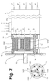
- This embodiment of the device according to the invention is intended for a nominal capacity of typically about 2500 to about 3300 l / h of deionized electrolyte solution.
- As electrodeionization module 1 it contains a wound module in which diluate and concentrate are passed in crossflow (with axially guided diluate).
- the axial inflows of the electrolyte solution to be desalinated are indicated by "P"("P” stands for permeate, since the added electrolyte is preferably already the permeate of an upstream, partially desalting reverse osmosis).
- P axial inflows of the electrolyte solution to be desalinated are indicated by "P"("P" stands for permeate, since the added electrolyte is preferably already the permeate of an upstream, partially desalting reverse osmosis).
- D are the axial outlets of the diluate.
- Ci designates the Concentrate Inlet and "Co” indicates Concentrate outlet.
- "+" And “-”
- the diluate outlets D of the electrodeionization module 1 open into a connection part 10 (for example made of polyoxymethylene copolymer) with a collecting space 11 and with nine passage openings for the diluate leaving the electrodeionization module 1 (only one of which is shown by reference numeral 101).
- a connection part 10 for example made of polyoxymethylene copolymer
- nine passage openings for the diluate leaving the electrodeionization module 1 (only one of which is shown by reference numeral 101).
- Each of the nine through-holes is drilled and designed so that it can be used in each case an ultrafiltration module using each a sealing ring (such as EPDM rubber or NBR).
- the total of nine ultrafiltration modules (only three of which are shown by the reference numerals 1201, 1202, 1203) are commercial legionella filters equipped with hollow fiber membranes with an exclusion limit of 100,000 Daltons.
- the hollow fibers are bent in a U-shape (see above general description).
- each ultrafiltration module 1201, 1202, 1203 The nominal maximum passage volume of each ultrafiltration module 1201, 1202, 1203 is about 800 l / h.
- the nine ultrafiltration modules are fitted between the connection part 10 and a filter support plate 14 with the aid of six chromium steel spacer supports (only one of which is shown by reference numeral 13).
- the filter retainer plate 14 again has nine apertures for the filtered permeate (only one is shown at reference numeral 15) into which the ultrafiltration modules are fitted by means of sealing rings of EPDM rubber, silicone rubber or NBR.
- the filter retaining plate 14 has on its outer side a collecting space 16 for the filtered diluate. This collecting space 16 is closed by a screwed flange 17 with central outlet 18.
- the composite of connector 10, the nine ultrafiltration modules, the six distance supports and the filter retaining plate 14 is shown cut in the figure.
- the connecting part 10 is again shown in the figure at the bottom left in the plan view, seen from the ultrafiltration modules forth; Here, the position of the cutting plane A-A ', in which said composite is shown cut indicated.
- the arrangement of all nine ultrafiltration modules is visible: six are arranged in a circular arrangement on the outside of the connecting part 3, the remaining three in the center of the connecting part 3.
- the six distance supports are shown here (only the one, cut in the sectional view visible support again provided with reference numeral 13).
- the dashed circle 11 indicates the collecting space for the diluate leaving the electrodeionization module 1; The dashed lines indicate that this collecting space is located on the back of the connecting part 10.
- the device according to embodiment 1 was also exposed to permeate from a reverse osmosis.
- the back pressure was solely generated by the two downstream ultrafiltration modules 21, 22, since there was no pressure holding valve.
- diluate was generated over 288 hours.
- the measured operating parameters are shown in FIG. As can be seen from FIG. 4, a constant water quality of 0.055-0.056 ⁇ S / cm is also achieved at a flow rate of 1000 l / h.
Landscapes
- Chemical & Material Sciences (AREA)
- Chemical Kinetics & Catalysis (AREA)
- Engineering & Computer Science (AREA)
- Water Supply & Treatment (AREA)
- Health & Medical Sciences (AREA)
- Urology & Nephrology (AREA)
- Separation Using Semi-Permeable Membranes (AREA)
- Water Treatment By Electricity Or Magnetism (AREA)
Abstract
Description
Die Erfindung betrifft eine neue Vorrichtung zur kontinuierlichen elektrochemischen Entsalzung und Filtration wässriger Lösungen in Form eines Wickelmoduls.The invention relates to a novel apparatus for continuous electrochemical desalination and filtration of aqueous solutions in the form of a wound module.
Das Einzelverfahren der Elektrodeionisation ist seit Ende der 1950iger Jahre bekannt. Eine Beschreibung des Verfahrens wird erstmals in
Wickelmodule zur Elektrodeionisation, bei denen sowohl die zu entsalzende wässerige Elektrolytlösung als auch das Konzentrat tangential (d.h. von der äusseren Mantelfläche spiralförmig nach innen zum Zentrum oder umgekehrt) geführt werden, sind etwa in der
Wickelmodule zur Elektrodeionisation, bei denen das Konzentrat tangential, aber der zu entsalzende Elektrolyt axial (d.h. von der einen Stirnseite des Moduls zur anderen Stirnseite) geführt ist, sind in der
In allen angeführten Ausführungsformen wird eine kontinuierliche elektrochemische Entsalzung beschrieben, bei der zwischen zwei Elektroden, Kathode und Anode, Kationen- und Anionenaustauschermembranen in alternierender Reihenfolge angeordnet sind. Der Raum zwischen zwei benachbarten Membranen definiert jeweils eine Verdünnungskammer bzw. eine Konzentratkammer. Die Verdünnungskammer ist entweder mit Ionenaustauscherharz und/oder ionenleitfähigem Material gefüllt, um die Kammergeometrie zu definieren. Die Konzentratkammer wird durch ein Netz aus Kunststoff (Spacer) und/oder ionenleitfähigem Material (z.B. Ionenaustauscherharz) gebildet. Die Anzahl an Verdünnungs- und Konzentratkammern kann von jeweils einer wiederholenden Einheit bis zu mehreren (techn. ausgeführt max. 36) variieren. Die jeweilig ausgeführten Möglichkeiten zur Abdichtung der einzelnen Kammern nach aussen sind den angeführten Patentschriften zu entnehmen.In all of the cited embodiments, a continuous electrochemical desalination is described in which cation and anion exchange membranes are arranged in alternating order between two electrodes, cathode and anode. The space between two adjacent membranes defines in each case a dilution chamber or a concentrate chamber. The dilution chamber is filled with either ion exchange resin and / or ionically conductive material to define the chamber geometry. The concentrate chamber is formed by a network of plastic (spacer) and / or ion-conductive material (eg ion exchange resin). The number of dilution and concentrate compartments can vary from one repeating unit to several (maximum 36). The respective options outlined for sealing the individual chambers to the outside can be found in the cited patents.
Im Betrieb der Module werden die Verdünnungskammer oder die Verdünnungskammern in einmaligem Durchlauf durchströmt während die Konzentratseite je nach Betriebsart in einmaligem oder mehrmaligem Durchlauf durchströmt werden kann. Die Verteilung des zuströmenden Wassers im Modul auf die einzelnen Kammern wird über interne Verteilsysteme erreicht.During operation of the modules, the dilution chamber or the dilution chambers are flowed through in a single pass while the concentrate side can be flowed through once or several times, depending on the operating mode. The distribution of the inflowing water in the module to the individual chambers is achieved via internal distribution systems.
Bei der Durchströmung der Verdünnungskammer unter Druck wird das aufzubereitende Wasser über das Ionenaustauscherharz geleitet. Entsprechend den Betriebsbedingungen können aufgrund der mechanischen Beanspruchung durch den Druckabfall über das Ionenaustauscherharz Abrieb und feine Partikel entstehen. Üblicherweise sind die Zu- und Abströmöffnungen der einzelnen Kammern so ausgestaltet, dass kein Ionenaustauscherkorn und grössere Bruchstücke des Ionenaustauscherkorns aus den Kammern ausgespült werden kann. Dies kann z.B. durch das Einbringen eines Harzfangnetzes bewerkstelligt werden. Die Trenngrenze des Netzes liegt bei ca. 200 µm. Kleinere Partikel können das Netz passieren und gelangen so mit dem Produktwasser in die nachfolgenden Verfahrensstufen der Wasseraufbereitung. Als Partikel können auch Mikroorganismen, deren Grösse üblicherweise zwischen 0,2 und 5 µm liegt, aus Verfahrensstufen vor dem Elektrodeionisationsmodul betrachtet werden, da der Prozess der Wasseraufbereitung z.B. für die pharmazeutische, die mikroelektronische oder die Kraftwerks-Industrie unter wirtschaftlicher Betrachtungsweise nicht unter sterilen Bedingungen durchgeführt wird. Um nachfolgende Verfahrensstufen vor Partikeln zu schützen, wird deshalb oft ein Membranmodul, etwa ein Ultrafiltrationsmodul, stromabwärts des Elektrodeionisationsmoduls in Reihe geschaltet.When passing through the dilution chamber under pressure, the water to be treated is passed over the ion exchange resin. Depending on the operating conditions, abrasion and fine particles may be generated due to the mechanical stress caused by the pressure drop across the ion exchange resin. Usually, the inlet and outlet openings of the individual chambers are designed so that no ion exchange grain and larger fragments of the ion exchange grain can be flushed out of the chambers. This can be done, for example, by introducing a resin trap net. The separation limit of the network is approx. 200 μm. Smaller particles can pass the net and get there with the product water in the subsequent process stages of water treatment. As particles and microorganisms whose size is usually between 0.2 and 5 microns, to be considered from process stages before the electrodeionization, since the process of water treatment, eg for the pharmaceutical, microelectronic or power plant industry from an economic point of view not under sterile conditions is carried out. Therefore, in order to protect subsequent process steps from particles, a membrane module, such as an ultrafiltration module, is often connected in series downstream of the electrodeionization module.
Bei dem Betrieb von Modulen zur Elektrodeionisation wie oben beschrieben hat sich andererseits gezeigt, dass sich die Packungsdichte des Ionenaustauscherharzes in der Verdünnungskammer günstig auf die erzielbare Qualität (Restleitfähigkeit) des Produktwassers auswirkt. Die Packungdichte des Ionentauschers lässt sich wiederum über den im Elektrodeionisationsmodul herrschenden Innendruck (nicht Druckabfall) beeinflussen. Zur Erzielung eines gewissen Innendrucks wurde bislang hinter dem Elektrodeionisationsmodul, aber vor dem Membranmodul ein Druckhalteventil vorgesehen, mit dem ein geeigneter Gegendruck auf der Produktwasserseite (Diluat) des Elektrodeionisationsmoduls angelegt wurde. Bei Wickelmodulen, bei denen der Fluss des Elektrolyten tangential geführt wird, wurde dieser Gegendruck etwa typisch zwischen 0,5 und 1 bar gewählt; bei Wickelmodulen, bei denen der Fluss des Elektrolyten axial geführt wird, betrug dieser Gegendruck typisch etwa 0,3 bis 3 bar.In the operation of modules for electrodeionization as described above, on the other hand, it has been shown that the packing density of the ion exchange resin in the dilution chamber has a favorable effect on the achievable quality (residual conductivity) of the product water. The packing density of the ion exchanger can in turn be influenced by the internal pressure (not pressure drop) prevailing in the electrodeionization module. To achieve a certain internal pressure, a pressure-maintaining valve has hitherto been provided behind the electrodeionization module, but before the membrane module, with which a suitable back pressure was applied to the product water side (diluate) of the electrodeionization module. In the case of winding modules in which the flow of the electrolyte is guided tangentially, this backpressure was chosen to be typically between 0.5 and 1 bar; in winding modules in which the flow of the electrolyte is axially guided, this back pressure was typically about 0.3 to 3 bar.
Der Erfindung stellt sich die Aufgabe, eine Vorrichtung und ein Verfahren bereitzustellen, bei denen der erforderliche Gegendruck auf der Diluatseite des Elektrodeionisationsmoduls bei dessen Betrieb erreicht werden kann, und gleichzeitig die Abtrennung von Partikeln, Abrieb vom Ionenaustauscherharz und/oder Mikroorganismen erzielt werden kann.The object of the invention is to provide an apparatus and a method in which the required back pressure on the diluate side of the electrodeionization module can be achieved during its operation, and at the same time the separation of particles, abrasion from the ion exchange resin and / or microorganisms can be achieved.
Die Aufgabe wird erfindungsgemäss gelöst durch eine Vorrichtung zur Elektrodeionisation einer wässerigen Elektrolytlösung, umfassend ein Elektrodeionisationsmodul, ein Ultrafiltrationsmodul und ein Verbindungsteil, das das Elektrodeionisationsmodul und das Ultrafiltrationsmodul dergestalt miteinander verbindet, dass es zum Leiten des beim Betrieb der Vorrichtung im Elektrodeionisationsmodul aus der Elektrolytlösung erzeugten Diluates vom Elektrodeionisationsmodul zum Ultrafiltrationsmodul befähigt ist, dadurch gekennzeichnet, dass die Vorrichtung in dem Verbindungsteil kein verstellbares Druckhalteventil aufweist.The object is achieved according to the invention by a device for electrodeionization of an aqueous electrolyte solution, comprising an electrodeionization module, an ultrafiltration module and a connecting part, which connects the electrodeionization module and the ultrafiltration module in such a way that it conducts the diluate produced from the electrolyte solution during operation of the device in the electrodeionization module from the electrodeionization module to the ultrafiltration module, characterized in that the device has no adjustable pressure-maintaining valve in the connection part.
Bevorzugte Ausführungsformen der erfindungsgemässen Vorrichtung ergeben sich aus den Unteransprüchen.Preferred embodiments of the device according to the invention will become apparent from the dependent claims.
Es wurde überraschenderweise gefunden, dass sich ein stromabwärts des Elektrodeionisationsmodul liegendes Ultrafiltrationsmodul nicht nur zur Abtrennung von Ionentauscherresten und Bakterien aus dem Diluat, sondern gleichzeitig auch zur Erzeugung des Gegendrucks hinter dem Elektrodeionisationsmodul eignet, der für den Erhalt der Packungsdichte des Ionentauschers im Elektrodeionisationsmodul wichtig ist. Dies ist auch deswegen überraschend, weil diese Ultrafiltrationsmodule keinen konstanten, vorhersagbaren Gegendruck erzeugen; sie setzen sich im Verlauf ihres Betriebs allmählich mit Filterrückständen zu und erzeugen so einen zeitlich ansteigenden Gegendruck hinter dem Elektrodeionisationsmodul. Durch die Verwendung der Ultrafiltrationsmodule als gegendruckerzeugende Mittel erübrigt sich der Einbau eines Druckhalteventils im oder hinter dem Elektrodeionisationsmodul, oder vor oder im Ultrafiltrationsmodul.It has surprisingly been found that an ultrafiltration module located downstream of the electrodeionization module is suitable not only for separating ion exchanger residues and bacteria from the diluate, but also for generating the backpressure behind the electrodeionization module, which is important for maintaining the packing density of the ion exchanger in the electrodeionization module. This is also surprising because these ultrafiltration modules do not produce a constant, predictable backpressure; They settle gradually with filter residues in the course of their operation and thus generate a time-increasing backpressure behind the electrodeionization module. The use of the ultrafiltration modules as counterpressure-producing means makes it unnecessary to install a pressure-maintaining valve in or behind the electrodeionization module, or before or in the ultrafiltration module.
Als "Elektrodeionisationsmodul" wird im Rahmen der vorliegenden Anmeldung jede elektrochemische Zelle verstanden, die umfasst:
- a) ein elektrolytlösunggefülltes oder elektrolytlösungdurchströmtes Kathodenkompartiment mit einer Kathode und einer Kationentauschermembran, wobei die Kationentauschermembran eine der räumlichen Begrenzungen des Kathodenkompartiments bildet und die das Kathodenkompartiment füllende oder durchströmende Elektrolytlösung (= Katholyt) sowohl mit der Kathode als auch mit der Kationentauschermembran in Berührung kommt;
- b) ein elektrolytlösunggefülltes oder elektrolytlösungdurchströmtes Anodenkompartiment mit einer Anode und einer Anionentauschermembran, wobei die Anionentauschermembran eine der räumlichen Begrenzungen des Anodenkompartiments bildet und die das Anodenkompartiment füllende oder durchströmende Elektrolytlösung (= Anolyt) sowohl mit der Anode als auch mit der Anionentauschermembran in Berührung kommt; und
- c) ein Zwischenkompartiment, wobei die besagte Kationentauschermembran und die besagte Anionentauschermembran zwei der räumlichen Begrenzungen dieses Zwischenkompartimentes bilden. Das Zwischenkompartiment kann gewünschtenfalls durch weitere in seinem Inneren paarweise vorhandene und voneinander beabstandet angeordnete Kationen- und Anionentauschermembranen in Subkompartimente unterteilt sein. Alle Kationen- und Anionentauschermembranen, die das Zwischenkompartiment begrenzen und gewünschtenfalls unterteilen, sind entlang dem Gradienten des elektrischen Feldes betrachtet in alternierender Reihenfolge angeordnet. In Richtung von der Kathode zur Anode entlang dem Gradienten des elektrischen Feldes betrachtet ist jedes von einem Kationentauschermembran/Anionentauschermembran-Paar eingeschlossene Subkompartiment mit einem Ionentauscherharz, bevorzugt einem Mischbetttauscherharz, oder mit einem ioneleitfähigen Material gefüllt und wird von der zu entsalzenden Elektrolytlösung durchströmt (= "Diluatkammern"), währenddem jedes von einem Anionentauschermembran/Kationentauschermembran-Paar begrenzte Subkompartiment von aufzukonzentrierender Elektrolytlösung durchströmt wird (= "Könzentratkammern"). Auch die im Kathodenkompartiment a) und Anodenkompartiment b) vorhandene Elektrolytlösung wird im elektrochemischen Betrieb an Elektrolyten aufkonzentriert, daher sind diese ebenfalls "Konzentratkammern". Die Elektrolytlösung in einer Diluatkammer kommt mit den beiden die Diluatkammer begrenzenden Ionentauschermembranen in Berührung und wird mindestens durch eine solche Ionentauschermembran von der Elektrolytlösung einer angrenzenden Konzentratkammer getrennt.
- a) an electrolyte solution-filled or electrolyte solution-perfused cathode compartment having a cathode and a cation exchange membrane, wherein the cation exchange membrane forms one of the spatial boundaries of the cathode compartment and the cathode compartment filling or flowing electrolyte solution (= catholyte) contacts both the cathode and the cation exchange membrane;
- b) an electrolyte solution-filled or electrolyte solution-perfused anode compartment having an anode and an anion exchange membrane, wherein the anion exchange membrane forms one of the spatial boundaries of the anode compartment and the anode solution filling or flowing electrolyte solution (= anolyte) contacts both the anode and the anion exchange membrane; and
- c) an intermediate compartment, said cation exchange membrane and said anion exchange membrane being two of the spatial boundaries of said intermediate compartment form. If desired, the intermediate compartment may be divided into subcompartments by further cation and anion exchange membranes arranged in pairs and spaced apart from each other. All cation and anion exchange membranes which define and, if desired, subdivide the intermediate compartment are arranged in alternating order along the gradient of the electric field. Viewed from the cathode to the anode along the gradient of the electric field, each subcompartment enclosed by a cation exchange membrane / anion exchange membrane pair is filled with an ion exchange resin, preferably a mixed bed exchange resin, or with an ion conductive material, and is flowed through by the electrolyte solution to be desalted (= " Diluatkammern "), while each of an anion exchanger membrane / cation exchange membrane pair limited subcompartment of electrolyte solution to be concentrated is flowed through (=" Konzentratkammern "). Also in the cathode compartment a) and anode compartment b) existing electrolyte solution is concentrated in the electrochemical operation of electrolytes, therefore these are also "concentrate chambers". The electrolyte solution in a diluate chamber contacts the two ion exchange membranes delimiting the diluate chamber and is separated from the electrolyte solution of an adjacent concentrate chamber by at least one such ion exchange membrane.
Bevorzugte Beispiele von erfindungsgemäss verwendbaren Elektrodeionisationsmodulen sind die eingangs diskutierten Plattenmodule und Wickelmodule. Bei den Plattenmodulen werden die oben beschriebenen Konzentrat-und Diluatkammern alle im Parallelfluss zueiander durchströmt, ohne dass sie untereinander in Verbindung stehen. Bei einem Wickelmodul ist der Auslass jeweils einer Konzentratkammer mit dem Einlass einer (in Richtung des Gradienten des elektrischen Feldes gesehen) nächsten Konzentratkammer direkt verbunden (d.h dass Kationentauscher- bzw. Anionentauschermembran der einen Konzentratkammer nahtlos mit der Kationentauscher bzw. Anionentauschermembran verbunden sind), und Zu- und Abflüsse für das Konzentrat sind nur gerade im Anodenkompartiment und im Kathodenkompartiment vorgesehen. Desgleichen sind der Auslass jeweils einer Diluatkammer mit dem Einlass einer (in Richtung des Gradienten des elektrischen Feldes gesehen) nächsten Diluatkammer direkt verbunden, und ein Zufluss für die zu entsalzende Elektrolytlösung ist nur gerade in der einen äussersten Diluatkammer und der Abfluss für das Diluat ist nur gerade in der anderen entgegengesetzt äussersten Diluatkammer vorgesehen.Preferred examples of electrodeionization modules which can be used according to the invention are the plate modules and wound modules discussed in the introduction. In the case of the plate modules, the above-described concentrate and diluate chambers are all flowed through one another in parallel flow, without them intercommunicating keep in touch. In a winding module, the outlet of each concentrate chamber is directly connected to the inlet of a next concentrate chamber (viewed in the direction of the gradient of the electric field) (ie, cation exchanger or anion exchange membrane of one concentrate chamber is seamlessly connected to the cation exchanger or anion exchange membrane) Inlet and outflows for the concentrate are only provided in the anode compartment and in the cathode compartment. Likewise, the outlet of each diluate chamber is directly connected to the inlet of a next diluate chamber (seen in the direction of the electric field gradient), and an inflow for the electrolyte solution to be desalted is just in the one outermost diluate chamber and the diluate outflow is only just in the other opposite outermost Diluatkammer provided.
Eher bevorzugt sind die Wickelmodule, und darunter besonders bevorzugt sind diejenigen Wickelmodule, bei denen die Fliessrichtungen in den Konzentratkammern einerseits und zu entsalzender wässeriger Elektrolytlösung in den Diluatkammern andererseits kreuzförmig aufeinanderstehen; wobei die Fliessrichtung in den Diluatkammern parallel zur Wickelachse des Wickelmoduls, d.h. axial, verläuft.Rather preferred are the winding modules, and among those particularly preferred are those winding modules, in which the flow directions in the concentrate chambers on the one hand and desalting aqueous electrolyte solution in the diluate on the other hand cross-wise on one another; wherein the flow direction in the diluate chambers is parallel to the winding axis of the winding module, i. axial, runs.
Als "Ultrafiltrationsmodul" wird im Rahmen der vorliegenden Anmeldung jeder Filter verstanden, der zur filtrativen Entfernung von Mikroorganismen aus einer wässerigen Lösung befähigt ist. Ulrafiltrationsmodule enthalten hierzu typischerweise mindestens eine semipermeable Membran aus einem Polymer mit geeigneter Porengrösse. Beispiele für solche Polymere sind etwa Polyolefine wie Polyethylen, Polypropylen oder Poly(4-methylpenten-1); Polysulfone; Polyethersulfone; aromatische Polyamide; Polyimide; Polyamide-Imide; oder fluorhaltige Polymere wie Polyvinylidenfluorid, Polytetrafluorpropylen, Copolymere von Hexafluorpropylen und Tetrafluorpropylen. Die Ausschlussgrenze der Membran liegt typisch im Bereich von 5000 bis 400000 Dalton. Bevorzugt enthält ein erfindungsgemäss zu verwendendes Ultrafiltrationsmodul die semipermeable Membran in Form einer Vielzahl von Hohlfasern. Für Membranen in Form von Hohlfasern sind Polyvinylidenfluorid und Polyethersulfone als Polymere bevorzugt. Die Hohlfasern weisen bevorzugt eine Porenweite von etwa 0,01 bis etwa 0,2 µm, eher bevorzugt von etwa 0,05 bis etwa 0,2 µm, und bevorzugt einen Innendurchmesser von etwa 10 bis etwa 200 µm, eher bevorzugt von etwa 50 bis etwa 150 µm auf. Die gesamte Membranfläche, die von allen Hohlfasern in einem solchen Ultrafiltrationsmodul gebildet wird, beträgt bevorzugt etwa 0,01 bis etwa 3 m2, eher bevorzugt etwa 0,05 bis etwa 1,5 m2. Die Herstellung von Hohlfasern mit den obigen gewünschten Eigenschaften ist an sich seit langem bekannt; es wird nur beispielhaft auf den Abschnitt "
Die zu filtrierende wässerige Lösung wird von über eine Einlassöffnung in das Ultrafiltrationsmodul hineingeführt und kann entweder vom Aussenraum der Hohlfasern in deren Lumen eindringen oder aus dem Lumen der Hohlfaser in den Aussenraum herausdringen; ersteres ist bevorzugt. Die Hohlfasern können in dem Ultrafiltrationsmodul in Längsrichtung (etwa parallel zu einer Längsachse des Ultrafiltrationsmoduls) verlaufen, so dass sie darin ein lang gestrecktes Bündel bilden. Bevorzugt sind die Hohlfasern aber im Inneren des Ultrafiltrationsmoduls U-förmig gebogen und zeigen mit ihren offenen Enden zur Filtratseite des Ultrafiltrationsmoduls. Das zu filtrierende, von dem Elektrodeionisationsmodul stammende Diluat wird dabei in das Innere des Ultrafiltrationsmoduls geführt und dringt, wie bereits oben als bevorzugt erwähnt, in die Hohlfasern ein. Da beide Enden jeder Hohlfaser zur Filtratseite des Ultrafiltrationsmoduls zeigen, bilden beide Enden einen Auslass für das Filtat. Das aus den Hohlfasern austretende Filtrat kann über eine geeignete Auslassöffnung, die mit den Enden der Hohlfasern in hydraulischer Verbindung steht, dem Ultrafiltrationsmodul entnommen werden.The aqueous solution to be filtered is introduced into the ultrafiltration module via an inlet opening and can either penetrate from the outer space of the hollow fibers into its lumen or can be forced out of the lumen of the hollow fiber into the outer space; the former is preferred. The hollow fibers may be longitudinal in the ultrafiltration module (approximately parallel to a longitudinal axis of the ultrafiltration module) so as to form therein an elongate bundle. Preferably, however, the hollow fibers are bent U-shaped in the interior of the ultrafiltration module and point with their open ends to the filtrate side of the ultrafiltration module. The diluate to be filtered, originating from the electrodeionization module, is guided into the interior of the ultrafiltration module and, as already mentioned above, penetrates into the hollow fibers. Since both ends of each hollow fiber face the filtrate side of the ultrafiltration module, both ends form an outlet for the filtrate. The filtrate leaving the hollow fibers can be removed from the ultrafiltration module via a suitable outlet opening, which is hydraulically connected to the ends of the hollow fibers.
Als "Verbindungsteil, das das Elektrodeionisationsmodul und das Ultrafiltrationsmodul dergestalt miteinander verbindet, dass es zum Leiten des beim Betrieb der Vorrichtung im Elektrodeionisationsmodul aus der Elektrolytlösung erzeugten Diluates vom Elektrodeionisationsmodul zum Ultrafiltrationsmodul befähigt ist" wird jedes Bauteil verstanden, das eine solche Funktion ausüben kann. Beispiele hierfür sind Röhren, Leitungen, Schläuche, Stutzen oder auch ein Montage-oder Halterungsteil für das Elektrodeionisationsmodul und/oder das oder die Ultrafiltrationsmodul(e), das gleichzeitig Mittel zum diesem Leiten des Diluates (wie etwa inwendige Durchtrittsöffnungen oder Kanäle) aufweist. Ein solches Montage- oder Halterungsteil kann bevorzugt gleichzeitig auch ein Sammelsystem umfassen, das das aus mehreren Austrittsöffnungen des Elektrodeionisationsmoduls austretende Diluat sammelt und in einer einzigen Leitung zu dem Ultrafiltrationsmodul weiterleitet; es kann auch ein Verteilsystem enthalten, das das von dem Elektrodeionisationsmodul stammende Diluat gleichmässig auf mehrere, parallel geschaltete Ultrafiltrationseinheiten verteilt.As a "connection part that connects the electrodeionization module and the ultrafiltration module to each other such that it is capable of conducting the diluate generated from the electrolyte solution during operation of the device in the electrodeionization module from the electrodeionization module to the ultrafiltration module, any component that can perform such a function is understood. Examples include tubes, pipes, hoses, nozzles or even a mounting or holding part for the electrodeionization module and / or the ultrafiltration module (s), which at the same time comprises means for conducting the diluate (such as internal passage openings or channels). Such a mounting or holding part may preferably at the same time also comprise a collecting system which collects the diluate emerging from a plurality of outlet openings of the electrodeionization module and forwards them in a single line to the ultrafiltration module; it can also contain a distribution system that evenly distributes the diluate from the electrodeionization module to a plurality of ultrafiltration units connected in parallel.
Als "verstellbares Druckhalteventil" wird im Rahmen der vorliegenden Anmeldung ein Ventil verstanden, dessen in seinem Inneren auftretender Druckabfall variabel eingestellt werden kann. Die erfindungsgemässe Vorrichtung weist in dem Verbindungsteil und bevorzugt auch im Inneren des Elektrodeionisationsmoduls und im Inneren des Ultrafiltrationsmoduls kein solches Druckhalteventil auf. Wenn die erfindungsgemässe Vorrichtung mehrere Ultrafiltrationsmodule und entsprechend unter Umständen mehrere Verbindungen vom Elektrodeionisationsmodul zu jedem dieser Ultrafiltrationsmodul aufweist, enthält keine der Verbindungen und keines der Ultrafiltrationsmodule ein solches Ventil.As "adjustable pressure-maintaining valve" is understood in the context of the present application, a valve whose occurring inside pressure drop can be variably adjusted. The device according to the invention has no such pressure-maintaining valve in the connecting part and preferably also in the interior of the electrodeionisation module and in the interior of the ultrafiltration module. If the device according to the invention comprises a plurality of ultrafiltration modules and possibly several connections from the electrodeionization module to each of these ultrafiltration modules, none of the connections and none of the ultrafiltration modules contains such a valve.
Als "in hydraulischer Verbindung" stehend oder sich befindend sind im Rahmen der vorliegenden Anmeldung zwei Hohlräume oder Aussparungen (Sammelräume, Kanäle, Bohrungen,, Aussparungen, Verteilräume oder Durchrittsöffnungen), wenn sie den flüssigkeitsdichten Übertritt dieser Flüssigkeit vom einen zum anderen Hohlraum ohne nennenswerten Druckabfall gestatten.As "in hydraulic communication" standing or are located in the context of the present application, two cavities or recesses (plenums, channels, holes ,, recesses, distribution spaces or passage openings), if they the liquid-tight passage of this liquid from one to the other cavity without significant pressure drop allow.
Die Herstellung der erfindungsgemässen Vorrichtung ist fachüblich; da die verwendeten Elektodeionisationsmodule und Ultrafiltrationsmodule an sich bekannt sind. Die hydraulische Verbindung des oben beschriebenen Verbindungsteils mit den Ultrafiltrationsmodulen und dem Verteil- bzw. Abnahmesystem des Wickelmoduls kann durch Verkleben, Verschweissen oder durch eine Rohrverschraubung entsprechend der Materialpaarung ausgeführt werden.The preparation of the device according to the invention is customary in the art; since the Eleektodeionisationsmodule and ultrafiltration modules used are known per se. The hydraulic connection of the above-described connecting part with the ultrafiltration modules and the distribution and removal system of the winding module can be by gluing, welding or by a pipe fitting according to the material pairing be executed.
Eine weitere Möglichkeit der Verbindung der Ultrafiltrationsmodule mit dem Verbindungsteil in einem äusseren Gehäuserohr besteht in der Verwendung von ein oder mehreren Zugankern. Die Ultrafiltrationsmodule in den entsprechenden Durchtrittsöffnungen des Verbindungsteils werden durch Elastomerdichtungen gedichtet. Die Strömungsführung in der erfindungsgemässen Vorrichtung ergibt sich somit über einen Anschluss an der Zulaufseite, gewünschtenfalls ein integriertes Verteilsystem in dem Verbindungsteil (das das Diluat auf die Ultrafiltrationsmodule verteilt), der parallelen Durchströmung der einzelnen Ultrafiltrationsmodule, und gewünschtenfalls ein integriertes Sammelsystem in einer optionalen Filterhalterplatte (das das aus den Ultrafiltrationsmodulen austretende Filtrat sammelt). Der richtige Abstand zwischen Verbindungsteil und Filterhalteplatte kann gewünschtenfalls durch Streben oder Distanzstützen bewirkt werden. Der restliche Zwischenraum im Verbund Verbindungsteil / Ultrafiltrationseinheiten / Filterhalterplatte / optionale Distanzstützen ist nicht durchströmt und als Luftraum ausgeführt.Another way of connecting the ultrafiltration modules to the connector in an outer housing tube is to use one or more tie rods. The ultrafiltration modules in the corresponding passage openings of the connecting part are sealed by elastomer seals. The flow guidance in the device according to the invention thus results via a connection on the feed side, if desired an integrated distribution system in the connection part (which distributes the diluate to the ultrafiltration modules), the parallel flow through the individual ultrafiltration modules, and, if desired, an integrated collection system in an optional filter holder plate ( which collects the filtrate leaving the ultrafiltration modules). The correct distance between the connecting part and filter retaining plate can, if desired, be effected by struts or spacer supports. The remaining space in the composite connecting part / ultrafiltration units / filter holder plate / optional spacer supports is not flowed through and designed as air space.
Die einzelnen Ultrafiltrationsmodule werden typisch mit einem Volumenstrom von 100 1/h bis 600 1/h, vorzugsweise mit 250 bis 400 1/h, durchströmt. Die Anzahl an einzubauenden Ultrafiltrationsmodulen ergibt sich somit aus dem ganzzahligen Quotient des nominalen Volumenstroms des Elektrodeionisationsmoduls und dem bevorzugten Volumenstrom des einzelnen Ultrafiltrationsmoduls (d.h. z.B. für 500 1/h 2 Stück und für 1000 1/h mindestens 3 Stück).The individual ultrafiltration modules are typically flowed through with a volume flow of 100 l / h to 600 l / h, preferably with 250 to 400 l / h. The number of ultrafiltration modules to be installed thus results from the integer quotient of the nominal volume flow of the electrodeionization module and the preferred volume flow of the single ultrafiltration module (i.e., for example, 500 l / h 2 pieces and 1000 l / h at least 3 pieces).
Die hydraulische Verbindung des oben beschriebenen Verbindungsteils und der Filterhalterplatte mit den Ultrafiltrationseinheiten und dem Verteil- bzw. Abnahmesystem des Elektrodeionisationsmoduls kann durch einen Dichtring mit integrierter O-Ring Dichtung ausgeführt werden. Für die technische Umsetzung der Vorrichtung, ist das Elektrodeionisationsmodul bevorzugt von einem verstärkten Kunststoffmantel oder einem Stahl- oder Edelstahlrohr umgeben.The hydraulic connection of the above Connecting part and the filter holder plate with the ultrafiltration units and the distribution and acceptance system of the electrodeionization module can be performed by a sealing ring with integrated O-ring seal. For the technical implementation of the device, the electrodeionization module is preferably surrounded by a reinforced plastic jacket or a steel or stainless steel tube.
Für die technische Umsetzung ist die erfindungsgemässe Vorrichtung, umfassend (oder insbesondere bestehend aus) zur Elektrodeionisationsmodul, Ultrafiltrationsmodulen, Verbindungsteil und Filterhalterplatte von einem verstärkten Kunststoffmantel oder einem Stahl- oder Edelstahlrohr umgeben, das einen Festflansch aufweist. Die Verbindung von Elektrodeionisationsmodul und der Vorrichtung erfolgt durch Verschrauben des Flanschdeckels mit dem Festflansch.For technical implementation, the device according to the invention comprising (or in particular consisting of) the electrodeionization module, ultrafiltration modules, connecting part and filter holder plate is surrounded by a reinforced plastic jacket or a steel or stainless steel tube having a fixed flange. The connection of the electrodeionization module and the device takes place by screwing the flange cover to the fixed flange.
Die erfindungsgemässen Vorrichtungen eignen sich zur Elektrodeionisierung der üblicherweise hierfür eingesetzten Rohwässer. Dies sind beispielsweise natürliche Rohwässer, Leitungswasser oder Meerwasser. Diese enthalten alle gewisse Anteile an gelösten, in Ionen dissoziierte Salze und sind daher allesamt Elektrolyte. Vorzugsweise wird das Rohwasser vorgängig teilentsalzt und/oder enthärtet, etwa mittels einer vorgeschalteten Umkehrosmosestufe. Das Rohwasser, d.h. der zu entsalzende Elektrolyt, kann auch vorgängig einer keimtötenden Behandlung, etwa durch UV-Bestrahlung, Behandlung mit Ozon, Chlor oder Hypochlorit, unterzogen worden sein; es kann auch vorgängig bereits einer Filtration zur Entferung von Schwebeteilchen und/oder der Mikroorganismen unterzogen worden sein.The inventive devices are suitable for electrodeionization of the raw waters usually used for this purpose. These are, for example, natural raw water, tap water or seawater. These all contain certain amounts of dissolved salts dissociated into ions and are therefore all electrolytes. Preferably, the raw water is previously partially desalted and / or softened, for example by means of an upstream reverse osmosis stage. The raw water, ie the electrolyte to be desalted, may also have previously been subjected to a germicidal treatment, such as by UV irradiation, treatment with ozone, chlorine or hypochlorite; it may also be previously subjected to a filtration to remove suspended particles and / or microorganisms.
Die Erfindung wird nun unter Bezugnahme auf die Zeichnungen weiter veranschaulicht, in denen:
-
Figur 1 eine Schnittdarstellung einer ersten Ausführungsform der erfindungsgemässen Vorrichtung ist, die oben auch das darin verwendete Verbindungsteil in der Draufsicht nocheinmal zeigt; - Figur 2 eine Schnittdarstellung einer zweiten Ausführungsform der erfindungsgemässen Vorrichtung ist, die links unten auch das darin verwendete Verbindungsteil in der Draufsicht nocheinmal zeigt;
-
Figuren 3 bzw. 4 die Ergebnisse von Vergleichsversuchen hinsichtlich der Bildung und Qualität des Diluates bei einer vorbekannten Vorrichtung bzw. der Vorrichtung gemäss Ausführungsform 1 zeigen.
- Figure 1 is a sectional view of a first embodiment of the device according to the invention, which also shows the connection part used therein once again in the plan view above;
- FIG. 2 is a sectional view of a second embodiment of the device according to the invention, which also shows the connection part used in the plan view on the bottom left;
- Figures 3 and 4 show the results of comparative experiments in terms of the formation and quality of the diluate in a prior art device or the device according to
embodiment 1.
Bei dieser Ausführungsform wird als das Eletrodeionisationsmodul 1 ein Wickelmodul eingesetzt, bei dem die zu entsalzende Elektrolytlösung und das Konzentrat tangential durch die spiralförmig aufgewickelten Diluat- und Konzentratkammern geführt werden. Sie ist für eine nominale Kapazität von typisch etwa 400 bis etwa 700 1/h zu deionisierende Elektrolytlösung gedacht. Die hydraulischen und elektrischen Anschlüsse des Wickelmoduls sind hier nicht gezeigt. Diese Ausführungsform weist zwei Ultrafiltrationseinheiten 21, 22 (Hohlfasermembranfilter) auf. Diese sind handelsübliche Legionellenfilter, die mit Hohlfasermembranen mit einer Ausschlussgrenze von etwa 100000 Dalton ausgestattet sind. Die Hohlfasern sind U-förmig gebogen (siehe vorstehende allgemeine Beschreibung). Die beiden Ultrafiltrationseinheiten werden wickelmodulseitig von einem Verbindungsteil 3 gehalten. Auf der Filtratseite der beiden Ultrafiltrationseinheiten 21, 22 werden diese von einer Filterhalterplatte 4 gehalten. Verbindungsteil 3 und Filterhalterplatte 4 befinden sich in einem äusseren Gehäuserohr 5 aus Stahl, Edelstahl oder Kunststoff. Das Verbindungsteil 3 (das im oberen Teil der Figur nocheinmal als Draufsicht von den Ultrafiltrationsmodulen 21, 22 her gesehen gezeigt ist) weist eine Durchtrittsöffnung 6 auf, die das vom Wickelmodul stammende Diluat zu den beiden Ultrafiltrationseinheiten 21, 22 leitet. Innerhalb des Verbindungsteils 3 verläuft ein Kanal 7, der die Fassungen 211, 221 der beiden Ultrafiltrationseinheiten 21, 22 hydraulisch miteinander verbindet und so ein Verteilsystem bildet, das das aus der Durchtrittsöffnung 6 durchtretende Diluat auf die beiden Ultrafiltrationseinheiten 21, 22 verteilt. Zwischen Verbindungsteil 3 und Filterhalteplatte 4 sind auch zwei Distanzstützen 81, 82 aus Chromstahl vorhanden. Der Verbund aus Verbindungsteil 3, Ultrafiltrationseinheiten 21, 22, Filterhalteplatte 4, Gehäuserohr 5 und Distanzstützen 81, 82 ist in der Figur 1 entlang der Schnittebene A-A' geschnitten; deren Lage ist im oben nocheinmal gezeigten Verbindungsteil 3 angedeutet. Aufgrund der Lage der Schnittebene A-A' ist in der Figur 1 nur das eine Ultrafiltrationsmodul 22 und nur die eine Distanzstütze 81 sichtbar; der Kanal 7 ist deswegen in dieser Schnittdarstellung nicht sichtbar. Im Verbindungsteil 3 sind zur Aufnahme der Ultrafiltrationsmodule Bohrungen 211, 221 vorgesehen; in der Filterhalterplatte 4 sind ebenfalls entsprechende Bohrungen (nur eine mit Bezugszeichen 222 sichtbar) enthalten. Die Ultrafiltrationsmodule 21, 22 können in den einzelnen Bohrungen 211, 221, 222 durch Verkleben oder Verschweissen oder mit Dichtungsringen fest mit dem Verbindungsteil 3 und der Filterplatte 4 verbunden sein. Der Fluss des aus dem Wickelmodul austretenden Diluates geschieht somit durch die Durchtrittsöffnung 6, durch das besagte Verteilsystem in dem Verbindungsteil 3, durch die beiden Ultrafiltrationsmodule 21, 22 in Parallelschaltung und dann gewünschtenfalls durch ein entsprechendes, in die Filterhalterplatte integriertes Sammelsystem (in der Figur nicht gezeigt) und dann über einen ebenfalls optionalen, in der Figur nicht gezeigten Anschlussstutzen. Der Raum zwischen Verbindungsteil 3 und Filterhalterplatte 4 ausserhalb der Ultrafiltrationsmodule 21, 22 und dem Gehäuserohr 5 ist nicht durchströmt und als Luftraum ausgeführt. Die Ein- und Auslässe für das Konzentrat, die Zuflüsse für die zu entsalzende Elektrolytlösung und die elektrischen Anschlüsse sind in der Figur nicht gezeigt; sie wären ausserhalb des Gehäuserohrs 5 an der Stirnseite der Vorrichtung vorhanden. Die gesamte Vorrichtung gemäss Ausführungsform 1 kann in ein vorzugsweise zylindrisches Mantelteil 9 eingebaut werden.In this embodiment, as the
Diese Ausführungsform der erfindungsgemässen Vorrichtung ist für eine nominale Kapazität von typisch etwa 2500 bis etwa 3300 1/h zu deionisierender Elektrolytlösung gedacht. Sie enthält als Elektrodeionisationsmodul 1 ein Wickelmodul, in dem Diluat und Konzentrat im Kreuzstrom (mit axial geführtem Diluat) geführt sind. Mit "P" sind die axialen Zuflüsse der zu entsalzenden Elektrolytlösung angedeutet ("P" steht für Permeat, da der zugeführte Elektrolyt vorzugsweise bereits das Permeat einer vorgeschalteten, teilentsalzenden Umkehrosmose ist). Mit "D" sind die axialen Abflüsse des Diluates angedeutet. "Ci" bezeichnet dem Einlass für das Konzentrat (Concentrate Inlet) und "Co" den Auslass des Konzentrates (Concentrate outlet). Mit "+" und "-" sind auch die beiden Anschlüsse für die Gleichspannung angegeben. Die Diluatauslässe D des Elektrodeionisationsmoduls 1 münden in ein Verbindungsteil 10 (etwa aus Polyoxymethylen-Copolymer) mit einem Sammelraum 11 und mit neun Durchtrittsöffnungen für das aus dem Elektrodeionisationsmodul 1 austretende Diluat (nur eine davon ist mit Bezugszeichen 101 gezeigt). Jede der neun Durchtrittsöffnungen ist gebohrt und so ausgestaltet, dass darin je ein Ultrafiltrationsmodul unter Verwendung von je einem Dichtungsring (etwa aus EPDM-Kautschuk oder NBR) eingesetzt werden kann. Die insgesamt neun Ultrafiltationsmodule (nur drei davon sind mit den Bezugszeichen 1201, 1202, 1203 gezeigt) sind handelsübliche Legionellenfilter, die mit Hohlfasermembranen mit einer Ausschlussgrenze von 100000 Dalton ausgestattet sind. Die Hohlfasern sind U-förmig gebogen (siehe vorstehende allgemeine Beschreibung). Das nominale maximale Durchtrittsvolumen jedes Ultrafiltrationsmoduls 1201, 1202, 1203 beträgt etwa 800 l/h. Die neun Ultrafiltrationsmodule sind unter Zuhilfenahme von sechs Distanzstützen aus Chromstahl (nur eine davon ist mit Bezugszeichen 13 gezeigt) zwischen Verbindungsteil 10 und einer Filterhalteplatte 14 eingepasst. Die Filterhalteplatte 14 weist wiederum neun Durchtrittsöffnungen für das filtrierte Permeat auf (nur eine ist mit Bezugszeichen 15 gezeigt), in die die Ultrafiltrationsmodule mittels Dichtungsringen aus EPDM-Kautschuk, Silikonkautschuk oder NBR eingepasst sind. Auch die Filterhalteplatte 14 weist an ihrer Aussenseite einen Sammelraum 16 für das filtrierte Diluat auf. Dieser Sammelraum 16 wird durch einen aufgeschraubten Flanschdeckel 17 mit zentralem Auslassstutzen 18 abgeschlossen. Der Verbund aus Verbindungsteil 10, den neun Ultrafiltationsmodulen, den sechs Distanzstützen und der Filterhalteplatte 14 ist in der Figur geschnitten gezeigt. Das Verbindungsteil 10 ist in der Figur links unten nocheinmal in der Draufsicht, von den Ultrafiltrationsmodulen her gesehen, gezeigt; hier ist die Lage der Schnittebene A-A', in der der besagte Verbund geschnitten gezeigt ist, angedeutet. Hier ist auch die Anordnung aller neun Ultrafiltrationsmodule sichtbar: Sechs sind in kreisförmiger Anordnung aussen auf dem Verbindungsteil 3 angeordnet, die restlichen drei im Zentrum des Verbindungsteils 3. Auch die sechs Distanzstützen sind hier gezeigt (nur die eine, in der Schnittdarstellung geschnitten sichtbare Stütze ist wieder mit Bezugszeichen 13 versehen). Mit dem gestrichelten Kreis 11 ist der Sammelraum für das aus dem Elektrodeionisationsmodul 1 austretende Diluat angedeutet; die Strichelung deutet an, dass sich dieser Sammelraum auf der Rückseite des Verbindungsteils 10 befindet.This embodiment of the device according to the invention is intended for a nominal capacity of typically about 2500 to about 3300 l / h of deionized electrolyte solution. As
Dabei wurde einerseits eine herkömmliche Vorrichtung zur Elektrodeionisation, umfassend ein Wickelmodul gemäss
- Die Restleitfähigkeit des Diluates (in µS/cm);
- der Gegendruck im Diluat, also hinter dem Wicklungsmodul (in bar);
- ▲ A Die Produktionsrate an Diluat (in 1/h)
- ◆ der Druck im dem Wickelmodul zugeführten Umkehrosmose-Permeat (in bar); und
- ■ die Restleitfähigkeit im dem Wickelmodul zugeführten Umkehrosmose-Permeat (in µS/cm).
- The residual conductivity of the diluate (in μS / cm);
- the back pressure in the diluate, ie behind the winding module (in bar);
- ▲ A The production rate of diluate (in 1 / h)
- ◆ the pressure in the winding module fed reverse osmosis permeate (in bar); and
- ■ the residual conductivity in the reverse osmosis permeate fed into the winding module (in μS / cm).
Bei der herkömmlichen Vorrichtung wurde Wasser aus einer Umkehrosmose unter Druck dem Wickelmodul zugeführt. Auf der Diluatseite (Reinwasser) des Moduls wurde mittels des Druckhalteventils ein Gegendruck von ca. 1 bar eingestellt. Unter Anlegen eines typischen Potentials an den Elektroden des Wickelmoduls wurde über 192 Stunden Diluat erzeugt. Die gemessenen Betriebsparameter sind in Figur 3 dargestellt. Wie aus Figur 3 ersichtlich ist, wurde eine konstante Wasserqualität von 0,058 µS/cm bei einer Produktionsrate von 1000 1/h erreicht.In the conventional apparatus, water from reverse osmosis was supplied under pressure to the winding module. On the diluate side (pure water) of the module, a back pressure of approx. 1 bar was set by means of the pressure holding valve. Applying a typical potential at the electrodes of the wound module, diluate was produced for 192 hours. The measured operating parameters are shown in FIG. As can be seen from FIG. 3, a constant water quality of 0.058 μS / cm was achieved at a production rate of 1000 l / h.
Die Vorrichtung nach Ausführungsform 1 wurde ebenfalls mit Permeat aus einer Umkehrosmose beaufschlagt. Auf der Diluatseite (d.h. hinter dem Wickelmodul) der Vorrichtung wurde der Gegendruck allein durch die beiden nachgeschalteten Ultrafiltrationsmodule 21, 22 erzeugt, da hier kein Druckhalteventil vorhanden war. Nach dem Anlegen eines typischen Potentials an den Elektroden des Wickelmoduls wurde über 288 Stunden Diluat erzeugt. Die gemessenen Betriebsparameter sind in Figur 4 dargestellt. Wie aus Figur 4 ersichtlich ist, wird ebenfalls eine konstante Wasserqualität von 0,055 - 0,056 µS/cm bei einem Volumenstrom von 1000 1/h erreicht.The device according to
Claims (11)
Applications Claiming Priority (1)
| Application Number | Priority Date | Filing Date | Title |
|---|---|---|---|
| CH5702006 | 2006-04-06 |
Publications (3)
| Publication Number | Publication Date |
|---|---|
| EP1842580A2 true EP1842580A2 (en) | 2007-10-10 |
| EP1842580A3 EP1842580A3 (en) | 2008-10-08 |
| EP1842580B1 EP1842580B1 (en) | 2013-03-13 |
Family
ID=38283101
Family Applications (1)
| Application Number | Title | Priority Date | Filing Date |
|---|---|---|---|
| EP07007050A Active EP1842580B1 (en) | 2006-04-06 | 2007-04-04 | Device and continuous electrochemical desalination with an integrated membrane stage |
Country Status (4)
| Country | Link |
|---|---|
| US (2) | US20070246410A1 (en) |
| EP (1) | EP1842580B1 (en) |
| DK (1) | DK1842580T3 (en) |
| NO (1) | NO20071748L (en) |
Families Citing this family (8)
| Publication number | Priority date | Publication date | Assignee | Title |
|---|---|---|---|---|
| WO2015164318A1 (en) * | 2014-04-22 | 2015-10-29 | Purewater Therapeutics, LLC | Water treatment system |
| CN109952197A (en) | 2016-09-20 | 2019-06-28 | 阿夸曼布拉尼斯有限责任公司 | Penetrant flows pattern |
| JP6719667B2 (en) | 2016-11-19 | 2020-07-08 | アクア メンブレインズ,インコーポレイテッド | Interference pattern for spirally wound elements |
| EP3609607B1 (en) | 2017-04-12 | 2024-05-22 | Aqua Membranes, Inc. | Graded spacers for filtration wound elements |
| KR102355893B1 (en) | 2017-04-20 | 2022-01-26 | 아쿠아 멤브레인스 인코포레이티드 | Non-overlapping, non-deforming patterns for spiral wound elements |
| WO2018195367A1 (en) | 2017-04-20 | 2018-10-25 | Aqua Membranes Llc | Mixing-promoting spacer patterns for spiral-wound elements |
| CN111344053A (en) | 2017-10-13 | 2020-06-26 | 阿夸曼布拉尼斯公司 | Bridge support for spiral wound elements and reduced feed spacer |
| US11633700B2 (en) | 2020-04-07 | 2023-04-25 | Aqua Membranes Inc. | Independent spacers and methods |
Citations (7)
| Publication number | Priority date | Publication date | Assignee | Title |
|---|---|---|---|---|
| EP0417506A1 (en) * | 1989-09-08 | 1991-03-20 | Millipore Corporation | Electrodeionization and ultraviolet light treatment method for purifying water |
| EP0570341A1 (en) * | 1992-05-15 | 1993-11-18 | Christ AG | Apparatus for the continuous electrochemical desalination of aqueous solutions |
| US6190528B1 (en) * | 1998-03-19 | 2001-02-20 | Xiang Li | Helical electrodeionization apparatus |
| EP1222954A1 (en) * | 2001-01-05 | 2002-07-17 | Kurita Water Industries Ltd. | Method and apparatus for electrodeionization of water |
| US6461512B1 (en) * | 1999-08-11 | 2002-10-08 | Kurita Water Industries Ltd. | Method of disinfecting a deionized water producing apparatus and method of producing deionized water |
| US20020158014A1 (en) * | 2001-04-27 | 2002-10-31 | Kazuyuki Yamasaki | Metal containing waste water treatment method and metal containing waste water treatment equipment |
| WO2004101119A1 (en) * | 2003-05-17 | 2004-11-25 | Christ Ag | Spiral module with axial dilution flow |
Family Cites Families (11)
| Publication number | Priority date | Publication date | Assignee | Title |
|---|---|---|---|---|
| US2376253A (en) | 1944-04-07 | 1945-05-15 | Doughboy Machines Inc | Sealing machine |
| US4465573A (en) * | 1981-05-12 | 1984-08-14 | Hare Harry M O | Method and apparatus for the purification of water |
| US4925541B1 (en) * | 1984-07-09 | 1994-08-02 | Millipore Corp | Electrodeionization apparatus and method |
| US5045198A (en) * | 1989-08-04 | 1991-09-03 | Culligan International Company | Faucet-mounted microbial filter |
| US5114582A (en) * | 1991-04-12 | 1992-05-19 | W. R. Grace & Co.-Conn. | Filter element and spiral-wound membrane cartridge containing same |
| US6461520B1 (en) * | 1999-05-21 | 2002-10-08 | Life Spring Limited Partnership | User-activated ultra-violet water treatment unit |
| DE10115633A1 (en) * | 2001-03-23 | 2002-09-26 | Fuma Tech Gmbh | Shower water filter cartridge incorporates numerous porous hollow fibres |
| US6649037B2 (en) * | 2001-05-29 | 2003-11-18 | United States Filter Corporation | Electrodeionization apparatus and method |
| AU2002337876A1 (en) * | 2001-10-15 | 2003-04-28 | United States Filter Corporation | Apparatus for fluid purification and methods of manufacture and use thereof |
| EP1329425A1 (en) * | 2002-01-18 | 2003-07-23 | Toray Industries, Inc. | Desalination method and desalination apparatus |
| WO2010051528A1 (en) * | 2008-10-31 | 2010-05-06 | Siemens Water Technologies Corp. | Manifold block for reverse osmosis systems |
-
2007
- 2007-04-02 NO NO20071748A patent/NO20071748L/en not_active Application Discontinuation
- 2007-04-04 EP EP07007050A patent/EP1842580B1/en active Active
- 2007-04-04 DK DK07007050.3T patent/DK1842580T3/en active
- 2007-04-04 US US11/696,474 patent/US20070246410A1/en not_active Abandoned
-
2012
- 2012-09-25 US US13/626,094 patent/US8652326B2/en active Active
Patent Citations (7)
| Publication number | Priority date | Publication date | Assignee | Title |
|---|---|---|---|---|
| EP0417506A1 (en) * | 1989-09-08 | 1991-03-20 | Millipore Corporation | Electrodeionization and ultraviolet light treatment method for purifying water |
| EP0570341A1 (en) * | 1992-05-15 | 1993-11-18 | Christ AG | Apparatus for the continuous electrochemical desalination of aqueous solutions |
| US6190528B1 (en) * | 1998-03-19 | 2001-02-20 | Xiang Li | Helical electrodeionization apparatus |
| US6461512B1 (en) * | 1999-08-11 | 2002-10-08 | Kurita Water Industries Ltd. | Method of disinfecting a deionized water producing apparatus and method of producing deionized water |
| EP1222954A1 (en) * | 2001-01-05 | 2002-07-17 | Kurita Water Industries Ltd. | Method and apparatus for electrodeionization of water |
| US20020158014A1 (en) * | 2001-04-27 | 2002-10-31 | Kazuyuki Yamasaki | Metal containing waste water treatment method and metal containing waste water treatment equipment |
| WO2004101119A1 (en) * | 2003-05-17 | 2004-11-25 | Christ Ag | Spiral module with axial dilution flow |
Also Published As
| Publication number | Publication date |
|---|---|
| US20130020260A1 (en) | 2013-01-24 |
| EP1842580A3 (en) | 2008-10-08 |
| US20070246410A1 (en) | 2007-10-25 |
| NO20071748L (en) | 2007-10-08 |
| DK1842580T3 (en) | 2013-06-10 |
| US8652326B2 (en) | 2014-02-18 |
| EP1842580B1 (en) | 2013-03-13 |
Similar Documents
| Publication | Publication Date | Title |
|---|---|---|
| EP1842580B1 (en) | Device and continuous electrochemical desalination with an integrated membrane stage | |
| DE69738497T2 (en) | IMPROVED FILTRATION ARRANGEMENT WITH MICROPOROUS MEMBRANES | |
| DE69527021T2 (en) | Device and method for desalination of sea water by multi-stage reverse osmosis | |
| DE69301922T2 (en) | MODULES FOR ELECTROENTIONIZING DEVICE | |
| DE69023093T2 (en) | Water purification process. | |
| DE69934701T2 (en) | Process for the treatment of fluids | |
| EP2190561B1 (en) | Filter module and the stringing thereof to form a filter system | |
| DE19827473C1 (en) | Cross flow filter cartridge suiting diverse range of medical, industrial and laboratory applications | |
| DE8990025U1 (en) | Spiral wound membrane cell for reverse osmosis | |
| DE2424853A1 (en) | METHOD AND DEVICE FOR PROCESSING WHEY | |
| AT513225B1 (en) | Process for the filtration of liquids | |
| DE69735620T2 (en) | Apparatus for electrodialysis | |
| DE2525972A1 (en) | DEVICE FOR IMPLEMENTING THE MEMBRANE FILTRATION | |
| EP3241806B1 (en) | Terminal filter device for reduction of microbiological contaminants in an aqueous medium | |
| EP2352702B1 (en) | Water treatment process, and membrane separation process and water treatment plant suitable therefor | |
| DE19982837B4 (en) | Electrodialysis device | |
| DE102019132699A1 (en) | Device for filtering components from a fluid | |
| EP0592698B1 (en) | Ultra-filtration separator | |
| DE19520913A1 (en) | Method and device for water treatment according to the principle of reverse osmosis | |
| DE2652605A1 (en) | MEMBRANE MODULE FOR REVERSE OSMOSIS OR ULTRAFILTRATION | |
| DE102017127933A1 (en) | Disposable device for the filtration of a large volume of medium | |
| WO2001096002A1 (en) | Device for cross-flow filtration of liquids | |
| EP0675761B1 (en) | Method and installation for treating an aqueous solution by ion exchange | |
| DE19503191A1 (en) | Cross-flow filtration, to remove dispersion printing inks from process water | |
| DE4112231C2 (en) |
Legal Events
| Date | Code | Title | Description |
|---|---|---|---|
| PUAI | Public reference made under article 153(3) epc to a published international application that has entered the european phase |
Free format text: ORIGINAL CODE: 0009012 |
|
| AK | Designated contracting states |
Kind code of ref document: A2 Designated state(s): AT BE BG CH CY CZ DE DK EE ES FI FR GB GR HU IE IS IT LI LT LU LV MC MT NL PL PT RO SE SI SK TR |
|
| AX | Request for extension of the european patent |
Extension state: AL BA HR MK YU |
|
| RIN1 | Information on inventor provided before grant (corrected) |
Inventor name: BRAND, CHRISTIAN Inventor name: JOHANN, JUERGEN Inventor name: BISSEN, MONIQUE Inventor name: MENZEL, THOMAS Inventor name: SCHRAMM, THOMAS |
|
| RAP1 | Party data changed (applicant data changed or rights of an application transferred) |
Owner name: CHRIST WATER TECHNOLOGY AG |
|
| PUAL | Search report despatched |
Free format text: ORIGINAL CODE: 0009013 |
|
| AK | Designated contracting states |
Kind code of ref document: A3 Designated state(s): AT BE BG CH CY CZ DE DK EE ES FI FR GB GR HU IE IS IT LI LT LU LV MC MT NL PL PT RO SE SI SK TR |
|
| AX | Request for extension of the european patent |
Extension state: AL BA HR MK RS |
|
| RIC1 | Information provided on ipc code assigned before grant |
Ipc: B01D 63/02 20060101ALN20080829BHEP Ipc: B01D 61/14 20060101ALI20080829BHEP Ipc: B01D 63/10 20060101ALI20080829BHEP Ipc: B01D 61/58 20060101AFI20070730BHEP Ipc: B01D 61/48 20060101ALI20080829BHEP |
|
| 17P | Request for examination filed |
Effective date: 20090327 |
|
| AKX | Designation fees paid |
Designated state(s): AT BE BG CH CY CZ DE DK EE ES FI FR GB GR HU IE IS IT LI LT LU LV MC MT NL PL PT RO SE SI SK TR |
|
| RAP1 | Party data changed (applicant data changed or rights of an application transferred) |
Owner name: P & LS HOLDING GMBH |
|
| 17Q | First examination report despatched |
Effective date: 20110323 |
|
| GRAP | Despatch of communication of intention to grant a patent |
Free format text: ORIGINAL CODE: EPIDOSNIGR1 |
|
| GRAS | Grant fee paid |
Free format text: ORIGINAL CODE: EPIDOSNIGR3 |
|
| GRAA | (expected) grant |
Free format text: ORIGINAL CODE: 0009210 |
|
| AK | Designated contracting states |
Kind code of ref document: B1 Designated state(s): AT BE BG CH CY CZ DE DK EE ES FI FR GB GR HU IE IS IT LI LT LU LV MC MT NL PL PT RO SE SI SK TR |
|
| REG | Reference to a national code |
Ref country code: GB Ref legal event code: FG4D Free format text: NOT ENGLISH |
|
| REG | Reference to a national code |
Ref country code: CH Ref legal event code: EP Ref country code: AT Ref legal event code: REF Ref document number: 600452 Country of ref document: AT Kind code of ref document: T Effective date: 20130315 |
|
| REG | Reference to a national code |
Ref country code: IE Ref legal event code: FG4D Free format text: LANGUAGE OF EP DOCUMENT: GERMAN |
|
| REG | Reference to a national code |
Ref country code: DE Ref legal event code: R096 Ref document number: 502007011434 Country of ref document: DE Effective date: 20130508 |
|
| REG | Reference to a national code |
Ref country code: DK Ref legal event code: T3 |
|
| REG | Reference to a national code |
Ref country code: CH Ref legal event code: NV Representative=s name: BOHEST AG, CH |
|
| REG | Reference to a national code |
Ref country code: SE Ref legal event code: TRGR |
|
| PG25 | Lapsed in a contracting state [announced via postgrant information from national office to epo] |
Ref country code: LT Free format text: LAPSE BECAUSE OF FAILURE TO SUBMIT A TRANSLATION OF THE DESCRIPTION OR TO PAY THE FEE WITHIN THE PRESCRIBED TIME-LIMIT Effective date: 20130313 Ref country code: BG Free format text: LAPSE BECAUSE OF FAILURE TO SUBMIT A TRANSLATION OF THE DESCRIPTION OR TO PAY THE FEE WITHIN THE PRESCRIBED TIME-LIMIT Effective date: 20130613 Ref country code: ES Free format text: LAPSE BECAUSE OF FAILURE TO SUBMIT A TRANSLATION OF THE DESCRIPTION OR TO PAY THE FEE WITHIN THE PRESCRIBED TIME-LIMIT Effective date: 20130624 |
|
| PGFP | Annual fee paid to national office [announced via postgrant information from national office to epo] |
Ref country code: IE Payment date: 20130530 Year of fee payment: 7 Ref country code: DK Payment date: 20130618 Year of fee payment: 7 |
|
| REG | Reference to a national code |
Ref country code: NL Ref legal event code: T3 |
|
| REG | Reference to a national code |
Ref country code: LT Ref legal event code: MG4D |
|
| PG25 | Lapsed in a contracting state [announced via postgrant information from national office to epo] |
Ref country code: SI Free format text: LAPSE BECAUSE OF FAILURE TO SUBMIT A TRANSLATION OF THE DESCRIPTION OR TO PAY THE FEE WITHIN THE PRESCRIBED TIME-LIMIT Effective date: 20130313 Ref country code: GR Free format text: LAPSE BECAUSE OF FAILURE TO SUBMIT A TRANSLATION OF THE DESCRIPTION OR TO PAY THE FEE WITHIN THE PRESCRIBED TIME-LIMIT Effective date: 20130614 Ref country code: LV Free format text: LAPSE BECAUSE OF FAILURE TO SUBMIT A TRANSLATION OF THE DESCRIPTION OR TO PAY THE FEE WITHIN THE PRESCRIBED TIME-LIMIT Effective date: 20130313 Ref country code: FI Free format text: LAPSE BECAUSE OF FAILURE TO SUBMIT A TRANSLATION OF THE DESCRIPTION OR TO PAY THE FEE WITHIN THE PRESCRIBED TIME-LIMIT Effective date: 20130313 |
|
| PG25 | Lapsed in a contracting state [announced via postgrant information from national office to epo] |
Ref country code: CZ Free format text: LAPSE BECAUSE OF FAILURE TO SUBMIT A TRANSLATION OF THE DESCRIPTION OR TO PAY THE FEE WITHIN THE PRESCRIBED TIME-LIMIT Effective date: 20130313 Ref country code: PT Free format text: LAPSE BECAUSE OF FAILURE TO SUBMIT A TRANSLATION OF THE DESCRIPTION OR TO PAY THE FEE WITHIN THE PRESCRIBED TIME-LIMIT Effective date: 20130715 Ref country code: RO Free format text: LAPSE BECAUSE OF FAILURE TO SUBMIT A TRANSLATION OF THE DESCRIPTION OR TO PAY THE FEE WITHIN THE PRESCRIBED TIME-LIMIT Effective date: 20130313 Ref country code: SK Free format text: LAPSE BECAUSE OF FAILURE TO SUBMIT A TRANSLATION OF THE DESCRIPTION OR TO PAY THE FEE WITHIN THE PRESCRIBED TIME-LIMIT Effective date: 20130313 Ref country code: EE Free format text: LAPSE BECAUSE OF FAILURE TO SUBMIT A TRANSLATION OF THE DESCRIPTION OR TO PAY THE FEE WITHIN THE PRESCRIBED TIME-LIMIT Effective date: 20130313 Ref country code: IS Free format text: LAPSE BECAUSE OF FAILURE TO SUBMIT A TRANSLATION OF THE DESCRIPTION OR TO PAY THE FEE WITHIN THE PRESCRIBED TIME-LIMIT Effective date: 20130713 |
|
| PG25 | Lapsed in a contracting state [announced via postgrant information from national office to epo] |
Ref country code: CY Free format text: LAPSE BECAUSE OF FAILURE TO SUBMIT A TRANSLATION OF THE DESCRIPTION OR TO PAY THE FEE WITHIN THE PRESCRIBED TIME-LIMIT Effective date: 20130313 Ref country code: PL Free format text: LAPSE BECAUSE OF FAILURE TO SUBMIT A TRANSLATION OF THE DESCRIPTION OR TO PAY THE FEE WITHIN THE PRESCRIBED TIME-LIMIT Effective date: 20130313 |
|
| PG25 | Lapsed in a contracting state [announced via postgrant information from national office to epo] |
Ref country code: MC Free format text: LAPSE BECAUSE OF FAILURE TO SUBMIT A TRANSLATION OF THE DESCRIPTION OR TO PAY THE FEE WITHIN THE PRESCRIBED TIME-LIMIT Effective date: 20130313 |
|
| PLBE | No opposition filed within time limit |
Free format text: ORIGINAL CODE: 0009261 |
|
| STAA | Information on the status of an ep patent application or granted ep patent |
Free format text: STATUS: NO OPPOSITION FILED WITHIN TIME LIMIT |
|
| 26N | No opposition filed |
Effective date: 20131216 |
|
| PG25 | Lapsed in a contracting state [announced via postgrant information from national office to epo] |
Ref country code: IT Free format text: LAPSE BECAUSE OF FAILURE TO SUBMIT A TRANSLATION OF THE DESCRIPTION OR TO PAY THE FEE WITHIN THE PRESCRIBED TIME-LIMIT Effective date: 20130313 |
|
| REG | Reference to a national code |
Ref country code: DE Ref legal event code: R097 Ref document number: 502007011434 Country of ref document: DE Effective date: 20131216 |
|
| REG | Reference to a national code |
Ref country code: AT Ref legal event code: MM01 Ref document number: 600452 Country of ref document: AT Kind code of ref document: T Effective date: 20130404 |
|
| REG | Reference to a national code |
Ref country code: CH Ref legal event code: PCAR Free format text: NEW ADDRESS: HOLBEINSTRASSE 36-38, 4051 BASEL (CH) |
|
| PG25 | Lapsed in a contracting state [announced via postgrant information from national office to epo] |
Ref country code: AT Free format text: LAPSE BECAUSE OF NON-PAYMENT OF DUE FEES Effective date: 20130404 |
|
| REG | Reference to a national code |
Ref country code: DK Ref legal event code: EBP Effective date: 20140430 |
|
| REG | Reference to a national code |
Ref country code: IE Ref legal event code: MM4A |
|
| PG25 | Lapsed in a contracting state [announced via postgrant information from national office to epo] |
Ref country code: MT Free format text: LAPSE BECAUSE OF FAILURE TO SUBMIT A TRANSLATION OF THE DESCRIPTION OR TO PAY THE FEE WITHIN THE PRESCRIBED TIME-LIMIT Effective date: 20130313 |
|
| PG25 | Lapsed in a contracting state [announced via postgrant information from national office to epo] |
Ref country code: DK Free format text: LAPSE BECAUSE OF NON-PAYMENT OF DUE FEES Effective date: 20140430 Ref country code: IE Free format text: LAPSE BECAUSE OF NON-PAYMENT OF DUE FEES Effective date: 20140404 |
|
| PG25 | Lapsed in a contracting state [announced via postgrant information from national office to epo] |
Ref country code: TR Free format text: LAPSE BECAUSE OF FAILURE TO SUBMIT A TRANSLATION OF THE DESCRIPTION OR TO PAY THE FEE WITHIN THE PRESCRIBED TIME-LIMIT Effective date: 20130313 |
|
| PG25 | Lapsed in a contracting state [announced via postgrant information from national office to epo] |
Ref country code: LU Free format text: LAPSE BECAUSE OF NON-PAYMENT OF DUE FEES Effective date: 20130404 Ref country code: HU Free format text: LAPSE BECAUSE OF FAILURE TO SUBMIT A TRANSLATION OF THE DESCRIPTION OR TO PAY THE FEE WITHIN THE PRESCRIBED TIME-LIMIT; INVALID AB INITIO Effective date: 20070404 |
|
| REG | Reference to a national code |
Ref country code: FR Ref legal event code: PLFP Year of fee payment: 10 |
|
| REG | Reference to a national code |
Ref country code: FR Ref legal event code: PLFP Year of fee payment: 11 |
|
| REG | Reference to a national code |
Ref country code: FR Ref legal event code: PLFP Year of fee payment: 12 |
|
| P01 | Opt-out of the competence of the unified patent court (upc) registered |
Effective date: 20230419 |
|
| PGFP | Annual fee paid to national office [announced via postgrant information from national office to epo] |
Ref country code: NL Payment date: 20240408 Year of fee payment: 18 |
|
| PGFP | Annual fee paid to national office [announced via postgrant information from national office to epo] |
Ref country code: GB Payment date: 20240405 Year of fee payment: 18 |
|
| PGFP | Annual fee paid to national office [announced via postgrant information from national office to epo] |
Ref country code: DE Payment date: 20240326 Year of fee payment: 18 |
|
| PGFP | Annual fee paid to national office [announced via postgrant information from national office to epo] |
Ref country code: CH Payment date: 20240501 Year of fee payment: 18 |
|
| PGFP | Annual fee paid to national office [announced via postgrant information from national office to epo] |
Ref country code: FR Payment date: 20240403 Year of fee payment: 18 |
|
| PGFP | Annual fee paid to national office [announced via postgrant information from national office to epo] |
Ref country code: SE Payment date: 20240405 Year of fee payment: 18 Ref country code: BE Payment date: 20240415 Year of fee payment: 18 |