EP1841974B1 - Linear roller bearing - Google Patents
Linear roller bearing Download PDFInfo
- Publication number
- EP1841974B1 EP1841974B1 EP05821882.7A EP05821882A EP1841974B1 EP 1841974 B1 EP1841974 B1 EP 1841974B1 EP 05821882 A EP05821882 A EP 05821882A EP 1841974 B1 EP1841974 B1 EP 1841974B1
- Authority
- EP
- European Patent Office
- Prior art keywords
- guide rail
- scraper
- rolling bearing
- bearing according
- stop
- Prior art date
- Legal status (The legal status is an assumption and is not a legal conclusion. Google has not performed a legal analysis and makes no representation as to the accuracy of the status listed.)
- Not-in-force
Links
- 238000007789 sealing Methods 0.000 claims description 39
- 238000005096 rolling process Methods 0.000 claims description 26
- 238000007790 scraping Methods 0.000 claims description 13
- 239000000463 material Substances 0.000 claims description 5
- 238000011068 loading method Methods 0.000 claims 2
- 238000001816 cooling Methods 0.000 claims 1
- 239000000428 dust Substances 0.000 claims 1
- 239000007788 liquid Substances 0.000 claims 1
- 210000001331 nose Anatomy 0.000 description 12
- 230000003313 weakening effect Effects 0.000 description 2
- 239000002826 coolant Substances 0.000 description 1
- 230000000694 effects Effects 0.000 description 1
- 239000013013 elastic material Substances 0.000 description 1
- 210000003128 head Anatomy 0.000 description 1
- 239000000126 substance Substances 0.000 description 1
Images


Classifications
-
- F—MECHANICAL ENGINEERING; LIGHTING; HEATING; WEAPONS; BLASTING
- F16—ENGINEERING ELEMENTS AND UNITS; GENERAL MEASURES FOR PRODUCING AND MAINTAINING EFFECTIVE FUNCTIONING OF MACHINES OR INSTALLATIONS; THERMAL INSULATION IN GENERAL
- F16C—SHAFTS; FLEXIBLE SHAFTS; ELEMENTS OR CRANKSHAFT MECHANISMS; ROTARY BODIES OTHER THAN GEARING ELEMENTS; BEARINGS
- F16C29/00—Bearings for parts moving only linearly
- F16C29/08—Arrangements for covering or protecting the ways
- F16C29/084—Arrangements for covering or protecting the ways fixed to the carriage or bearing body movable along the guide rail or track
- F16C29/086—Seals being essentially U-shaped, e.g. for a U-shaped carriage
-
- F—MECHANICAL ENGINEERING; LIGHTING; HEATING; WEAPONS; BLASTING
- F16—ENGINEERING ELEMENTS AND UNITS; GENERAL MEASURES FOR PRODUCING AND MAINTAINING EFFECTIVE FUNCTIONING OF MACHINES OR INSTALLATIONS; THERMAL INSULATION IN GENERAL
- F16C—SHAFTS; FLEXIBLE SHAFTS; ELEMENTS OR CRANKSHAFT MECHANISMS; ROTARY BODIES OTHER THAN GEARING ELEMENTS; BEARINGS
- F16C29/00—Bearings for parts moving only linearly
- F16C29/04—Ball or roller bearings
- F16C29/06—Ball or roller bearings in which the rolling bodies circulate partly without carrying load
- F16C29/0633—Ball or roller bearings in which the rolling bodies circulate partly without carrying load with a bearing body defining a U-shaped carriage, i.e. surrounding a guide rail or track on three sides
- F16C29/0635—Ball or roller bearings in which the rolling bodies circulate partly without carrying load with a bearing body defining a U-shaped carriage, i.e. surrounding a guide rail or track on three sides whereby the return paths are provided as bores in a main body of the U-shaped carriage, e.g. the main body of the U-shaped carriage is a single part with end caps provided at each end
- F16C29/0638—Ball or roller bearings in which the rolling bodies circulate partly without carrying load with a bearing body defining a U-shaped carriage, i.e. surrounding a guide rail or track on three sides whereby the return paths are provided as bores in a main body of the U-shaped carriage, e.g. the main body of the U-shaped carriage is a single part with end caps provided at each end with balls
- F16C29/0642—Ball or roller bearings in which the rolling bodies circulate partly without carrying load with a bearing body defining a U-shaped carriage, i.e. surrounding a guide rail or track on three sides whereby the return paths are provided as bores in a main body of the U-shaped carriage, e.g. the main body of the U-shaped carriage is a single part with end caps provided at each end with balls with four rows of balls
- F16C29/0645—Ball or roller bearings in which the rolling bodies circulate partly without carrying load with a bearing body defining a U-shaped carriage, i.e. surrounding a guide rail or track on three sides whereby the return paths are provided as bores in a main body of the U-shaped carriage, e.g. the main body of the U-shaped carriage is a single part with end caps provided at each end with balls with four rows of balls with load directions in O-arrangement
Definitions
- the guide rail 1 has an upper side and two opposite longitudinal sides, wherein the longitudinal sides are each provided with a plurality of raceways 6 formed by ball grooves 5 for balls 7.
- the four ball grooves 5 of the guide rail 1 are arranged in o-arrangement to each other.
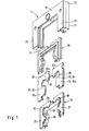
- FIG. 1 shows the individual parts of the scraper according to the invention 3.
- a housing 17 two formed of flexible material sheet-like seals 18 are arranged in the rail direction one behind the other. Between the two seals 18, a support plate 19 is arranged, on which the two seals 18 are supported with their sides facing the support plate 19.
- the housing 17 has seen in longitudinal section through the carriage 2 on an approximately U-shaped, open to the guide rail 1 section profile.
- the two leg portions 20, 21 of this section profile form a front wall and a rear wall of the housing 17, wherein the rear wall faces the carriage 2.
- a bottom part 22 connecting the two leg parts 20, 21 forms a circumferential wall of the housing 17.
Landscapes
- Engineering & Computer Science (AREA)
- General Engineering & Computer Science (AREA)
- Mechanical Engineering (AREA)
- Bearings For Parts Moving Linearly (AREA)
Description
Die vorliegende Erfindung betrifft Linearwälzlager, mit einem Führungswagen, der etwa u-förmig gebildet ist und mit seinen beiden Schenkeln eine Führungsschiene umgreift.The present invention relates to linear roller bearings, with a carriage, which is approximately U-shaped and engages around a guide rail with its two legs.
Aus
Wenn auf den Führungswagen eine Druckkraft ausgeübt wird, übertragen die Kugeln beider Lastkanäle diese Druckkraft.When a pressure force is exerted on the guide carriage, the balls of both load channels transmit this pressure force.
Der Führungswagen ist an seinen beiden Stirnseiten mit jeweils einem Abstreifer zum Abstreifen von Fremdstoffen wie Späne, Stäube und Kühlflüssigkeiten von der Führungsschiene versehen. Dieser Abstreifer weist eine Abstreifanlage auf, die durch eine Dichtlippe oder eine Dichtkante gebildet sein kann. Diese Abstreifanlage steht in Abstreifkontakt mit den Längsseiten und der Oberseite der Führungsschiene. Zu diesem Zweck weist dieser Abstreifer an seiner Abstreifanlage eine an die Führungsschiene angepasste Kontur auf, so dass die Abstreifanlage auch in die Kugelrillen eingreift.The guide carriage is provided at its two end faces, each with a scraper for stripping foreign substances such as chips, dusts and coolant from the guide rail. This scraper has a Stripping system, which may be formed by a sealing lip or a sealing edge. This wiper system is in wiping contact with the longitudinal sides and the top of the guide rail. For this purpose, this scraper on its stripping a on the guide rail adapted contour, so that the scraper engages in the ball grooves.
Ein gattungsgemässe Abstreifanlage ist aus derA generic Abstreifanlage is from the
Wenn der Führungswagen auf die Führungsschiene montiert wird, ist darauf zu achten, dass der Abstreifer mit seiner Abstreifanlage einwandfrei zur Führungsschiene ausgerichtet ist. Dies ist erforderlich, damit ein einwandfreier Abstreifkontakt des Abstreifers mit der Führungsschiene gewährleistet ist. Erst bei lagerichtiger Positionierung des Abstreifers kann dieser an den Führungswagen fixiert werden.If the carriage is mounted on the guide rail, it must be ensured that the wiper and its wiper system are perfectly aligned with the guide rail. This is necessary so that a perfect wiping contact of the scraper is ensured with the guide rail. Only when correct positioning of the scraper this can be fixed to the carriage.
Wenn die Abstreifanlage durch eine Dichtlippe gebildet ist, liegt diese Dichtlippe unter leichter elastischer Vorspannung sowohl an der Oberseite als auch an den beiden Längsseiten der Führungsschiene an. Betrachtet man den Teil der Dichtlippen, der an beiden Längsseiten der Führungsschiene anliegt ohne Berücksichtigung jenes Teils der Dichtlippe, der an der Oberseite der Führungsschiene anliegt, sind die elastischen Rückstellkräfte der auf beiden Seiten der Führungsschiene anliegenden Dichtlippe in einem Kräftegleichgewicht. Es ist möglich, dass aufgrund dieses Kräftegleichgewichts eine einwandfreie Positionierung des Abstreifers gegeben ist. Tatsächlich wirken jedoch zusätzlich die elastischen Rückstellkräfte des Teils der Dichtlippe, der an die Oberseite der Führungsschiene angedrückt ist. Die hier wirksame Rückstellkraft der Dichtlippe zieht den Abstreifer nach oben, so dass die an die Längsseiten der Führungsschiene angedrückten Teile der Dichtlippe ebenfalls nach oben gezogen werden. Das bedeutet jedoch, dass die in die Zuglaufbahn der Führungsschiene eingreifenden Teile der Dichtlippe unzulässig zusammengedrückt werden. Eine einwandfreie Wirkung des Abstreifers ist somit nicht gewährleistet. Wenn der Abstreifer in dieser falschen Position am Führungswagen fixiert wird, stellt sich zumindest ein deutlich erhöhter Verschleiß an den Dichtlippen im Bereich der Zuglaufbahn ein.If the scraping system is formed by a sealing lip, this sealing lip is under slight elastic bias on both the top and on the two longitudinal sides of the guide rail. Considering the part of the sealing lips, which rests on both longitudinal sides of the guide rail without consideration of that part of the sealing lip, which bears against the upper side of the guide rail, the elastic restoring forces of the applied on both sides of the guide rail sealing lip in an equilibrium of forces. It is possible that due to this balance of forces proper positioning of the scraper is given. In fact, however, additionally act the elastic restoring forces of the part of the sealing lip, which is pressed against the top of the guide rail. The effective here restoring force of the sealing lip pulls the scraper upwards, so that the pressed against the longitudinal sides of the guide rail parts of the sealing lip are also pulled upwards. This means, however, that the engaging in the train track of the guide rail parts of the sealing lip are compressed inadmissible. A perfect effect of the scraper is thus not guaranteed. If the scraper is fixed in this wrong position on the carriage, at least a significantly increased wear on the sealing lips in the area of the train track.
Dieses Problem kann auch bei Linearwälzlagern auftreten, die lediglich in einer Ebene gelagert sind.This problem can also occur with linear bearings, which are stored only in one plane.
Aufgabe der vorliegenden Erfindung ist es, ein Linearwälzlager nach den Merkmalen des Oberbegriffs des Anspruchs 1 anzugeben, bei dem ein einfaches Ausrichten des Abstreifers zur Führungsschiene möglich ist.Object of the present invention is to provide a linear roller bearing according to the features of the preamble of claim 1, in which a simple alignment of the scraper to the guide rail is possible.
Erfindungsgemäß wird diese Aufgabe dadurch gelöst, dass der Abstreifer einen ersten Anschlag zum Anschlagen an die Führungsschiene aufweist, wobei das Anschlagen des ersten Anschlags eine unzulässige Lage des Abstreifers auf der Führungsschiene angibt.According to the invention this object is achieved in that the scraper has a first stop for abutment against the guide rail, wherein the abutment of the first stop indicates an impermissible position of the scraper on the guide rail.
Wenn der erste Anschlag wie beschrieben in der einen Richtung anschlägt, kann es zweckmäßig sein, einen zweiten Anschlag zum Anschlagen an die Führungsschiene vorzusehen, wobei das Anschlagen des zweiten Anschlags ebenfalls eine unzulässige Lage des Abstreifers auf der Führungsschiene angibt. Dieser zweite Anschlag ist dann in der gleichen Achse wie der erste Anschlag wirksam, jedoch in der entgegengesetzter Richtung. Beim Ausrichten des Abstreifers an der Führungsschiene können beim Einstellen erst der eine, und dann der andere Anschlag angefahren werden. Dann kann in Kenntnis der beiden Anschlagsituationen eine mittlere Stellung des Abstreifers in Bezug auf die Führungsschiene angefahren werden, wobei in dieser mittleren Position der Abstreifer an dem Führungswagen festgesetzt werden kann.If the first stop strikes in one direction as described, it may be expedient to provide a second stop for abutment against the guide rail, wherein the abutment of the second stop also indicates an impermissible position of the wiper on the guide rail. This second stop is then effective in the same axis as the first stop, but in the opposite direction. When aligning the scraper on the guide rail can be approached when adjusting first one, and then the other stop. Then, in the knowledge of the two stop situations, a middle position of the scraper with respect to the guide rail can be approached, in which middle position of the scraper can be fixed to the carriage.
Der erfindungsgemäße Anschlag ist besonders bei Linearwälzlagern geeignet, bei denen der Führungswagen etwa u-förmig gebildet ist und mit seinen beiden Schenkeln die Führungsschiene umgreift. Die Führungsschiene hat eine Oberseite und zwei Längsseiten, wobei die Längsseiten mit Laufbahnen für die Wälzkörper versehen sind. An den Schenkeln des Führungswagens sind ebenfalls Laufbahnen vorgesehen, die gemeinsam mit den Laufbahnen der Führungsschiene Lastkanäle für die Wälzkörper begrenzen. Der Abstreifer steht mit den Längsseiten und der Oberseite der Führungsschiene in Abstreifkontakt.The stop according to the invention is particularly suitable for linear roller bearings, in which the guide carriage is approximately U-shaped and engages around the guide rail with its two legs. The guide rail has an upper side and two longitudinal sides, wherein the longitudinal sides are provided with raceways for the rolling elements. On the legs of the guide carriage also tracks are provided which limit together with the raceways of the guide rail load channels for the rolling elements. The scraper is in strip contact with the long sides and the top of the guide rail.
Wenn der Abstreifer an der Führungsschiene ausgerichtet wird, kann beispielsweise der Abstreifer aufgrund der elastischen Rückstellkräfte der mit der Oberseite der Führungsschiene in Absteifkontakt stehenden Dichtlippe soweit nach oben verschoben sein, dass der erste Anschlag gegen die Führungsschiene anschlägt. Dann kann es genügen den Abstreifer etwas zurückzunehmen, so dass der Anschlag wieder frei ist. Der Abstreifer kann dann an dem Führungswagen fixiert werden.If the scraper is aligned with the guide rail, for example, the scraper due to the elastic restoring forces of standing with the top of the guide rail in Absteifkontakt sealing lip be moved so far up that the first stop abuts against the guide rail. Then it may be sufficient to take back the scraper something, so that the stop is free again. The scraper can then be fixed to the carriage.
Der erste Anschlag kann beispielsweise so ausgebildet sein, dass er gegen die Zuglaufbahn der Führungsschiene anschlägt.The first stop, for example, be designed so that it abuts against the train track of the guide rail.
Der zweite Anschlag kann so ausgebildet sein, dass er gegen die Oberseite der Führungsschiene anschlägt.The second stop may be formed so that it abuts against the top of the guide rail.
Es ist zweckmäßig, dass die Abstreifianlage den Anschlag in Richtungen auf die Führungsschiene überragt. Es genügt, wenn die Abstreifanlage um einige wenige zehntel Millimeter den Anschlag überragt. Auf diese Weise ist sichergestellt, dass selbst in der Anschlagsituation keine zu große Deformation der Abstreifianlage erfolgt.It is expedient that the stripping plant projects beyond the stop in directions on the guide rail. It is sufficient if the wiper system projects beyond the stop by a few tenths of a millimeter. In this way it is ensured that even in the attack situation no excessive deformation of the stripping plant takes place.
Erfindungsgemäße Linearwälzlager können beispielsweise vier Lastkanäle aufweisen, die in X- oder in O-Anordnung zueinander stehen. Der erste Anschlag kann dann auf einfache Art und Weise so gebildet sein, dass er gegen die jeweilige Zuglaufbahn des Lastkanals anschlägt. Wenn Zugbelastungen des Führungswagens von den Wälzkörpern in den ersten Lastkanälen übertragen werden, können Druckbelastungen des Führungswagens von den Wälzkörpern in den zweiten Lastkanälen übertragen werden.Linear roller bearings according to the invention can have, for example, four load channels which are in the X or O arrangement with respect to one another. The first stop can then be formed in a simple manner so that it abuts against the respective train track of the load channel. When tensile loads of the guide carriage are transmitted from the rolling elements in the first load channels, pressure loads of the guide carriage can be transmitted from the rolling elements in the second load channels.
Der etwa u-förmige Abstreifer ist vorzugsweise an seinen beiden Schenkeln in Abstreifkontakt mit den Längsseiten und mit seinen die beiden Schenkel verbindenden Quersteg in Abstreifkontakt mit der Oberseite der Führungsschiene. Bei dieser Ausbildung können die bereits zuvor beschriebenen vorteilhaften Ausbildungen problemlos umgesetzt werden.The approximately U-shaped scraper is preferably at its two legs in stripping contact with the longitudinal sides and with its connecting the two legs crosspiece in stripping contact with the top of the guide rail. In this embodiment, the previously described advantageous embodiments can be implemented easily.
Der Abstreifer kann eine mit der Abstreifanlage versehene plattenförmige Dichtung aufweisen. Da diese Dichtungen oftmals aus einem biegeweichen elastischen Werkstoff gebildet sind, kann es zweckmäßig sein, wenn der Abstreifer eine steife Stützplatte als Stütze für die Dichtung aufweist. Eine erfindungsgemäße Weiterbildung sieht vor, dass diese Stützplatte zu dem mit dem ersten und mit dem zweiten Anschlag versehen ist. Die Stützplatte übernimmt demzufolge mehrere Funktionen, die ohne großen Aufwand bereitgestellt sind.The wiper may have a plate-shaped seal provided with the wiper. Since these seals are often formed from a flexible elastic material, it may be useful if the scraper has a rigid support plate as a support for the seal. A further development according to the invention provides that this support plate is provided to the one with the first and with the second stop. The support plate therefore takes over several functions that are provided without much effort.
Wenn die Führungsschiene an jeder Längsseite beispielsweise mit zwei Kugelrillen versehen ist, kann der Abstreifer mit zwischen und in diese beiden Kugelrillen eingreifenden Nasen versehen sein. Diese Nasen der Stützplatte können jeweils mit dem ersten Anschlag versehen sein.If the guide rail is provided on each longitudinal side, for example with two ball grooves, the scraper can be provided with intervening and in these two ball grooves lugs. These lugs of the support plate can each be provided with the first stop.
Die Nasen der Dichtung können mit ihrer Abstreifanlage in Abstreifkontakt mit den Laufbahnen der Führungsschiene stehen. Auch hier kann es zweckmäßig sein, dass im Bereich der Nasen die Abstreifanlage den an der Nase der Stützplatte vorgesehenen ersten Anschlag etwas überragt. Die Stützplatte und die Dichtung können formschlüssig miteinander verbunden sein, so dass eine eindeutige Ausrichtung der Stützplatte und der Dichtung zueinander gewährleistet ist.The noses of the seal can be in scraping contact with the tracks of the guide rail with their wiper system. Again, it may be appropriate that in the area of the lugs Abstreifanlage projects beyond the provided on the nose of the support plate first stop something. The support plate and the seal can be positively connected to each other, so that a clear alignment of the support plate and the seal is ensured to each other.
Weiter oben wurde bereits erwähnt, dass der Abstreifer u-förmig ausgebildet sein kann. In diesem Fall kann die Stützplatte an ihrem die Führungsschiene an ihrer Oberseite übergreifenden Quersteg mit dem zweiten Anschlag versehen sein. Dieser zweite Anschlag kann dann problemlos gegen die Oberseite der Führungsschiene beim Ausrichten des Abstreifers anschlagen.It has already been mentioned above that the wiper can be U-shaped. In this case, the support plate may be provided with the second stop at its cross-piece which overlaps the guide rail at its upper side. This second stop can then easily strike against the top of the guide rail when aligning the scraper.
Nachstehend wird die Erfindung anhand eines in insgesamt vier Figuren abgebildeten Ausführungsbeispieles näher erläutert. Es zeigen:
- Figur 1
- einen erfindungsgemäßen Abstreifer in Explosionsdarstellung,
Figur 2- den Abstreifer aus
Figur 1 in perspektivischer Darstellung, geschnitten und Figur 3- in perspektivischer und vergrößerter Darstellung eine Dichtung des Abstreifers gemäß
Figur 2 und - Figur 4
- ein erfindungsgemäßes Linearwälzlager teilweise geschnitten.
- FIG. 1
- a scraper according to the invention in an exploded view,
- FIG. 2
- the scraper off
FIG. 1 in perspective, cut and - FIG. 3
- in perspective and enlarged view of a seal of the scraper according to
FIG. 2 and - FIG. 4
- a linear roller bearing according to the invention partially cut.
Das in
Die Führungsschiene 1 weist eine Oberseite und zwei einander gegenüberliegende Längsseiten auf, wobei die Längsseiten jeweils mit mehreren durch Kugelrillen 5 gebildete Laufbahnen 6 für Kugeln 7 versehen sind. Die vier Kugelrillen 5 der Führungsschiene 1 sind in o-Anordnung zueinander angeordnet.The guide rail 1 has an upper side and two opposite longitudinal sides, wherein the longitudinal sides are each provided with a plurality of raceways 6 formed by ball grooves 5 for balls 7. The four ball grooves 5 of the guide rail 1 are arranged in o-arrangement to each other.
Der Führungswagen 2 weist an seinen beiden Schenkeln 4 an seinen den Längsseiten der Führungsschiene 1 zugewandten Seiten jeweils zwei den Laufbahnen 6 gegenüberliegende Laufbahnen 8 auf, die ebenfalls als Kugelrillen 9 gebildet sind. Die Kugelrillen 5, 9 der Führungsschiene 1 und des Führungswagens 2 begrenzen erste und zweite Lastkanäle 10, 11, in denen die Kugeln 7 unter Last an den Kugelrillen 5, 9 abwälzen. Gestrichelt angedeutete Umlenkkanäle 12, 13 und Rücklaufkanäle 14, 15 verbinden Anfang und Ende der Lastkanäle 10, 11 endlos miteinander.The
Wenn an dem Führungswagen 2 Zugkräfte angreifen, die den Führungswagen 2 nach oben weg von der Führungsschiene 1 ziehen, übertragen die Kugeln 7 der ersten Lastkanäle 10 die Last. Der Lastkanal 10 weist demzufolge eine Zuglaufbahn auf. Wenn auf den Führungswagen 2 Druckkräfte einwirken, übertragen die zweiten Lastkanäle die Last. Der Lastkanal 11 weist demzufolge eine Drucklaufbahn auf.When tensile forces on the
Der Abstreifer 3 ist an seinem Innenumfang mit einer Abstreifanlage 16 versehen, die vorliegend durch eine Dichtlippe 16a gebildet ist, wie insbesondere der weiter unten beschriebenen
Der Abstreifer 3 wird nun nachstehend anhand der
Das Gehäuse 17 weist im Längsschnitt durch den Führungswagen 2 gesehen ein etwa u-förmiges, zur Führungsschiene 1 geöffnetes Schnittprofil auf. Die beiden Schenkelteile 20, 21 dieses Schnittprofils bilden eine Vorderwand und eine Rückwand des Gehäuses 17, wobei die Rückwand dem Führungswagen 2 zugewandt ist. Ein die beiden Schenkelteile 20, 21 verbindendes Bodenteil 22 bildet eine Umfangswand des Gehäuses 17.The
Das Gehäuse 17 ist mit einer erster Aufnahme 23 für die Stützplatte 19 versehen. Wenn die Stützplatte 19 einwandfrei in der ersten Aufnahme 23 angeordnet ist die Stützplatte 19 in allen Raumachsen positionsgenau ausgerichtet.
Das Gehäuse 17 ist ferner mit einer zweiten Aufnahme 24 für die beiden Dichtungen 18 versehen. Die beiden zweiten Aufnahmen 24 sind ebenfalls in der
Die plattenförmigen Dichtungen 18 können problemlos aus dem Gehäuse 17 herausgenommen und durch andere Dichtungen ersetzt werden. Wenn der Führungswagen mit dem montierten Abstreifer 3 auf der Führungsschiene 1 angeordnet ist, braucht lediglich der Abstreifer 3 von dem Führungswagen 2 gelöst zu werden. Dann kann das Gehäuse 17 des Abstreifers 3 nach oben von der Führungsschiene 1 abgenommen werden. Die beiden Dichtungen 18 und die Stützplatte 19 können zunächst auf der Führungsschiene 1 verbleiben. Da die beiden Dichtungen 18 vorzugsweise aus einem biegeweichen Material gebildet sind, können diese derart gebogen werden, dass sie von der Führungsschiene 1 abgenommen werden können. Nun können neue Dichtungen aufgesetzt werden und das Gehäuse kann wieder aufgeführt werden.The plate-shaped
Die Dichtungen 18 und die Stützplatte 19 sind darüber hinaus formschlüssig miteinander verbunden. Wie der
Bei dem hier dargestellten vierreihigen Linearwälzlager mit O-Anordnung sind die Kugelrillen 5, 9 an der Führungsschiene 1 derart angeordnet, dass die beiden Schenkel 27 der u-förmig gebildeten Dichtung 18 an ihren einander zugewandten Seiten jeweils mit einer vorspringenden Nase 27 versehen sind.
Zwischen der Nase 28 und dem die beiden Schenkel 27 verbindenden Quersteg 29 der Dichtung 18 erfährt die Dichtlippe 16a entlang ihrer Kontur ausgeprägte Umlenkungen. Auf diese Weise sind formbedingte steifigkeitserhöhte Stellen entlang der Ersteckung der Dichtlippe 16a ausgebildet. Da es jedoch vorteilhaft ist, wenn der Anpressdruck der Dichtlippe 16a an die Führungsschiene 1 gleichmäßig erfolgt, sind an diesen steifigkeitserhöhten Stellen gezielte Materialschwächungen an der Dichtung 18 vorgesehen. Diese gezielten Materialschwächungen bestehen im Ausführungsbeispiel darin, dass an den steifigkeitserhöhten Stellen mehrere die Dichtung 18 durchdringende, Schlitze 30 bildende Ausnehmungen vorgesehen. Diese Schlitze 30 sind mit geringem Abstand zu den Dichtlippen 16a angeordnet. An diesen Stellen sind demzufolge die Dichtlippen 16a nicht abgestützt, und können in Richtung auf die Schlitze 30 einfedern. Auf diese Weise kann gezielt ein gleichmäßiger Andruck der Dichtlippe 16a entlang der gesamten Erstreckung gewährleistet werden.Between the
Diese Schlitze 30 sind sowohl im Bereich der Nasen 28 als auch im Bereich von Ecken vorgesehen, die von den beiden Schenkeln 27 und dem Quersteg 29 gebildet sind.These
Wenn Dichtungen 18 für derartige Linearwälzlager an den Führungswagen 2 montiert werden sollen, ist darauf zu achten, dass die Dichtungen 18 einwandfrei zur Führungsschiene 2 ausgerichtet sind. Anderenfalls ist kein einwandfreier Abstreifkontakt des Abstreifers 3 mit der Führungsschiene 1 gewährleistet. Das positionsgenaue Ausrichten der Dichtung 18 - sei es nun bei Abstreifern mit oder ohne Gehäuse - wird durch die wirksamen elastischen Rückstellkräfte der an der Führungsschiene 1 anliegenden Dichtlippe 16a erschwert, was nachstehend erläutert wird. Denkt man sich die Dichtlippe 16a im Bereich des Querstegs 29 weg, besteht auf der Oberseite der Führungsschiene 1 keinerlei Konkakt der Dichtung mit der Führungsschiene 1. Lediglich die beiden Schenkel 27 mit ihrer Dichtlippe 16a stehen dann in Abstreifkontakt mit der Führungsschiene 1. In diesem Fall sind die Dichtlippen 16a elastisch gegen die Längsseiten der Führungsschiene 1 angefedert. Die wirksamen Andruckkräfte der Dichtlippen 16a zu beiden Seiten der Führungsschiene 1 stehen in einem Kräftegleichgewicht, so dass in dieser Situation eine einwandfreie Ausrichtung der Dichtung 18 in Bezug auf die Führungsschiene 1 gegeben ist.If
Tatsächlich wirken jedoch zusätzlich elastische Rückstellkräfte der Dichtlippe 16a im Bereich des Quersteges 29, so daß die Dichtung 18 nach oben weg von der Führungsschiene 1 gefedert oder gezogen wird. Das bedeutet, dass die Dichtlippen 16a im Bereich der Nasen 28 in erhöhtem Maße gegen die die Zuglaufbahn bildende Kugelrille 5 des ersten Wälzkörperkanals 10 der Führungsschiene 1 angedrückt werden.In fact, however, additionally act elastic restoring forces of the sealing
Wenn der Abstreifer 3 in dieser unzulässigen Ausrichtung an dem Führungswagen 2 festgesetzt wird, unterliegt die Dichtlippe 16a einem erhöhten Verschleiß, so daß eine zuverlässige Abstreifwirkung nicht gewährleistet ist. Um sicher zu stellen, dass bei der Montage des Abstreifers an den Führungswagen keine unzulässige Verformung der Dichtlippe auftreten kann, ist der Abstreifer 3 mit einem Anschlag 31 versehen, wie
Der
Der Abstreifer 3 ist mit einem weiteren Anschlag 33 versehen. Dieser Anschlag 33 ist an dem schon weiter oben beschriebenen Vorsprung 25 der Stützplatte 19 ausgebildet. Die Dichtlippe 16a überragt diesen Anschlag 33 in Richtung auf die Oberseite der Führungsschiene 1. Wenn der Abstreifer 3 während der Montage an den Führungswagen 2 zu weit nach unten gedrückt wird, schlägt der Anschlag 33 gegen die Oberseite der Führungsschiene 1 an. Die an der Oberseite anliegende Dichtlippe 16a wird aufgrund des Anschlags 33 nicht unzulässig stark gegen die Oberseite angedrückt, wird also nicht beschädigt. Der Abstreifer 3 ist zwischen den beiden beschriebenen Anschlagsituationen, vorzugsweise Mittenlage, einwandfrei positioniert und kann an den Führungswagen 2 fixiert werden.The
Claims (15)
- Linear rolling bearing, having a guide carriage (2) which is mounted by means of rolling bearings on a guide rail (1), and having a scraper (3), arranged at at least one end side of the guide carriage (2), for scraping foreign objects such as chips, dust and cooling liquids from the guide rail (1), with the scraper (3) being in scraping contact, by means of its scraping system (16), preferably sealing lip (16a) or sealing edge, with the guide rail (1), characterized in that the scraper (3) has a first stop (31) for abutment against the guide rail (1), and in that the scraper (3) has a second stop (33) for abutment against the guide rail (1), with the scraper (3) being positioned on the guide carriage between these two stop positions.
- Linear rolling bearing according to Claim 1, in which the guide carriage (2) is of approximately u-shaped design and engages with its two limbs (4) around the guide rail (1) which has an upper side and, situated opposite one another, two longitudinal sides, with the two longitudinal sides being provided with raceways (6) for rolling bodies, which raceways (6), together with raceways (8) provided on the limbs (4) of the guide carriage (2), delimit load channels (10, 11) for the rolling bodies, with the scraper (3) being in scraping contact, by means of its scraping system (16), with the longitudinal sides and with the upper side of the guide rail (1).
- Linear rolling bearing according to Claim 1, in which the first and the second stop (31, 33) act in a common axis, which is arranged transversely with respect to the guide rail (1), and in opposite directions.
- Linear rolling bearing according to Claim 2, in which the first stop (31) is designed for abutment against the raceway (6) of the guide rail (1) of the first or of the second load channel (10, 11).
- Linear rolling bearing according to Claim 1, in which the scraping system (16) projects beyond the stop (31, 33) in directions of the guide rail (1).
- Linear rolling bearing according to Claim 2, in which the longitudinal sides of the guide rail (1) and the two limbs (4) of the guide carriage are provided in each case with a plurality of raceways (6, 8) for rolling bodies, with raceways (6, 8), which face one another, of the guide rail (1) and of the guide carriage (2) delimiting load channels (10, 11) which are in an X-arrangement or O-arrangement with one another.
- Linear rolling bearing according to Claim 2, in which tensile loadings of the guide carriage (2) are transmitted by the rolling bodies into the first load channels (10, 11), and compressive loadings of the guide carriage (2) are transmitted by the rolling bodies into the second load channels (10, 11).
- Linear rolling bearing according to Claim 2, in which the approximately u-shaped scraper is in scraping contact, by means of its two limbs (27), with the longitudinal sides of the guide rail (1), and, by means of its transverse web (29) which connects the two limbs (27), with the upper side of the guide rail (1).
- Linear rolling bearing according to Claim 1, in which the scraper (3) has a plate-shaped seal (18) which is provided with the scraping system (16).
- Linear rolling bearing according to Claim 9, in which the scraper (3) has a rigid support plate (19) as a support for the seal (18) which is formed from flexible material.
- Linear rolling bearing according to Claim 10, in which the support plate (19) is provided with the first and with the second stop (31, 33).
- Linear rolling bearing according to Claims 2 and 10, in which the seal (18) and the support plate (19) are provided on their limbs (19a, 27) in each case with lugs (28, 32) which project in the direction of the in each case other limb (19a, 27), with the lugs (32) of the support plate (19) being provided in each case with the first stop (31).
- Linear rolling bearing according to Claim 12, in which the lugs (28) of the seal (18) are in scraping contact, by means of their scraping system (16), with the raceways (6) of the guide rail (1).
- Linear rolling bearing according to Claim 3, in which the support plate (19) and the seal (18) engage into one another in a form-fitting manner at at least one point.
- Linear rolling bearing according to Claim 11, in which the support plate (19) is provided with the second stop on its transverse web (25a) which engages over the guide rail (1) at its upper side.
Applications Claiming Priority (2)
| Application Number | Priority Date | Filing Date | Title |
|---|---|---|---|
| DE102005003710A DE102005003710A1 (en) | 2005-01-27 | 2005-01-27 | linear bearings |
| PCT/EP2005/013637 WO2006079397A1 (en) | 2005-01-27 | 2005-12-17 | Linear roller bearing |
Publications (2)
| Publication Number | Publication Date |
|---|---|
| EP1841974A1 EP1841974A1 (en) | 2007-10-10 |
| EP1841974B1 true EP1841974B1 (en) | 2013-05-15 |
Family
ID=35788262
Family Applications (1)
| Application Number | Title | Priority Date | Filing Date |
|---|---|---|---|
| EP05821882.7A Not-in-force EP1841974B1 (en) | 2005-01-27 | 2005-12-17 | Linear roller bearing |
Country Status (6)
| Country | Link |
|---|---|
| US (1) | US7789564B2 (en) |
| EP (1) | EP1841974B1 (en) |
| JP (1) | JP5125515B2 (en) |
| CN (1) | CN101111689B (en) |
| DE (1) | DE102005003710A1 (en) |
| WO (1) | WO2006079397A1 (en) |
Families Citing this family (12)
| Publication number | Priority date | Publication date | Assignee | Title |
|---|---|---|---|---|
| JP5032288B2 (en) * | 2007-12-11 | 2012-09-26 | 日本トムソン株式会社 | Linear motion guide unit with wiper seal |
| JP4834067B2 (en) * | 2008-12-26 | 2011-12-07 | 上銀科技股▲分▼有限公司 | Ball screw |
| JP5289217B2 (en) * | 2009-06-30 | 2013-09-11 | 日本トムソン株式会社 | Linear motion guidance unit |
| JP5720142B2 (en) * | 2010-08-19 | 2015-05-20 | 日本精工株式会社 | Linear guide device |
| JP5691393B2 (en) * | 2010-10-26 | 2015-04-01 | 日本精工株式会社 | Side guide for linear guide device, linear guide device |
| US8956047B2 (en) * | 2010-11-18 | 2015-02-17 | Nsk Ltd. | Linear guide bearing device and seal member used for the same |
| JP5760402B2 (en) * | 2010-11-19 | 2015-08-12 | 日本精工株式会社 | Side guide for linear guide device, linear guide device |
| WO2013042312A1 (en) * | 2011-09-21 | 2013-03-28 | 日本精工株式会社 | Linear motion guide device |
| JP6171391B2 (en) * | 2012-02-22 | 2017-08-02 | 日本精工株式会社 | Linear motion guide device |
| JP6193021B2 (en) * | 2013-07-04 | 2017-09-06 | 日本トムソン株式会社 | Linear motion guidance unit |
| US9809950B2 (en) * | 2015-11-05 | 2017-11-07 | Deere & Company | Two stage moldboard rail cleaner |
| TWM543944U (en) * | 2017-03-29 | 2017-06-21 | Airtac Int Group | Oil scraper of liner sliding rail |
Family Cites Families (18)
| Publication number | Priority date | Publication date | Assignee | Title |
|---|---|---|---|---|
| NL6807674A (en) * | 1968-05-31 | 1969-12-02 | ||
| JPH0515619Y2 (en) * | 1987-03-13 | 1993-04-23 | ||
| US5087130A (en) * | 1990-03-20 | 1992-02-11 | Nippon Seiko Kabushiki Kaisha | Under seal device of linear movement guide bearing |
| DE4114892A1 (en) * | 1991-05-07 | 1992-11-12 | Schaeffler Waelzlager Kg | SCRAPER UNIT FOR A LINEAR BEARING ELEMENT |
| DE4141038A1 (en) * | 1991-12-12 | 1993-06-17 | Schaeffler Waelzlager Kg | SCRAPER UNIT FOR A BEARING ELEMENT |
| DE9422394U1 (en) * | 1993-04-16 | 2001-07-05 | Rexroth Star Gmbh | A linear guide unit |
| JP3635497B2 (en) | 1994-03-04 | 2005-04-06 | 日本トムソン株式会社 | Linear motion rolling guide unit |
| US5556206A (en) * | 1994-10-24 | 1996-09-17 | Ameropean Corp. | Replacement wiper for linear bearing systems |
| JPH08200362A (en) * | 1995-01-20 | 1996-08-06 | Nippon Seiko Kk | Lubricant-containing polymer lubrication linear guide device |
| JP3331280B2 (en) * | 1995-07-31 | 2002-10-07 | 日本トムソン株式会社 | Linear motion rolling guide unit |
| JPH09317765A (en) | 1996-05-27 | 1997-12-09 | Nippon Thompson Co Ltd | Direct acting rolling guide unit |
| WO1998021493A1 (en) * | 1996-11-11 | 1998-05-22 | Thk Co., Ltd. | Linear motion device and lubricating oil supplying device for it |
| DE19713747A1 (en) * | 1997-04-04 | 1998-10-08 | Rieter Ingolstadt Spinnerei | Method and device for filtering fibers from an air stream |
| US6401867B1 (en) * | 1998-04-16 | 2002-06-11 | Thk Co., Ltd. | Lubricant supply system |
| DE1073848T1 (en) * | 1998-04-29 | 2001-07-05 | Thomson Ind Inc | LINEAR GUIDE WITH BUILT-IN DEVICE FOR IMPROVING PERFORMANCE |
| JP2000035038A (en) * | 1998-07-16 | 2000-02-02 | Nippon Thompson Co Ltd | Direct acting guide unit equipped with lubricating plate |
| JP4004873B2 (en) * | 2001-09-21 | 2007-11-07 | Thk株式会社 | Guide device sealing device and guide device |
| DE10307882A1 (en) * | 2003-02-25 | 2004-09-02 | Ina-Schaeffler Kg | linear bearings |
-
2005
- 2005-01-27 DE DE102005003710A patent/DE102005003710A1/en not_active Withdrawn
- 2005-12-17 EP EP05821882.7A patent/EP1841974B1/en not_active Not-in-force
- 2005-12-17 JP JP2007552522A patent/JP5125515B2/en not_active Expired - Fee Related
- 2005-12-17 WO PCT/EP2005/013637 patent/WO2006079397A1/en active Application Filing
- 2005-12-17 CN CN2005800473396A patent/CN101111689B/en not_active Expired - Fee Related
- 2005-12-17 US US11/814,858 patent/US7789564B2/en not_active Expired - Fee Related
Also Published As
| Publication number | Publication date |
|---|---|
| DE102005003710A1 (en) | 2006-08-17 |
| JP5125515B2 (en) | 2013-01-23 |
| US20080131037A1 (en) | 2008-06-05 |
| JP2008528896A (en) | 2008-07-31 |
| EP1841974A1 (en) | 2007-10-10 |
| CN101111689B (en) | 2011-03-23 |
| US7789564B2 (en) | 2010-09-07 |
| CN101111689A (en) | 2008-01-23 |
| WO2006079397A1 (en) | 2006-08-03 |
Similar Documents
| Publication | Publication Date | Title |
|---|---|---|
| EP1841974B1 (en) | Linear roller bearing | |
| WO2006079396A2 (en) | Linear roller bearing comprising a u-shaped scraper element on the end face of a guide carriage | |
| DE102007056862B4 (en) | Linear roller bearing with deflection piece | |
| EP2616700B1 (en) | Peripheral sealing arrangement | |
| EP2182229B1 (en) | Linear rolling bearing | |
| DE69217871T2 (en) | Rolling bearings for linear movements | |
| DE3304783C2 (en) | ||
| EP1843873A2 (en) | Linear roller bearing with a u-shaped scraper arranged on the front face of the guide carriage | |
| DE3153257C2 (en) | Ball bearing carriage unit for linear motion | |
| DE3805392C2 (en) | ||
| DE69307428T2 (en) | Rolled linear guide unit | |
| DE4311515C2 (en) | Rolling bearings for linear movements | |
| DE102010049944A1 (en) | Carriage with lubricating valve | |
| DE102007056860B4 (en) | Linear roller bearings with common locking elements for rolling element filling channels | |
| DE102007056877A1 (en) | Guiding wagon for linear roller bearing, has main body which is supported in longitudinally displaced manner by continuous circumferential rolling body row at guide rail extending in longitudinal direction | |
| DE102007056858B4 (en) | Two-piece return tube for a linear roller bearing | |
| EP1226364A1 (en) | Guide rail for a linear bearing | |
| DE102010008933A1 (en) | Linear guide for use in linear roller bearing, has base body comprising side pressurized with force by spring element, where side is provided at distance from guide rail, and spring element is supported against surface of brackets | |
| DE102008052083B4 (en) | Linear roller bearings with a lubrication channel | |
| DE19821329B4 (en) | linear bearings | |
| DE4438566A1 (en) | Linear rolling bearing with support body | |
| EP2261523B1 (en) | Gasket | |
| DE4027738B4 (en) | Wälzlinearführung | |
| DE19841668A1 (en) | Machine tool sliding carriage bearing has oil seal strips which do not come into contact with irregular surfaces, minimizing mechanical wear and extending service life | |
| DE102007056859A1 (en) | Guiding wagon for linear antifriction bearing, is supported in moving lengthwise manner by rolling element slat at guiding disk that extends in longitudinal direction, where longitudinal seal is provided |
Legal Events
| Date | Code | Title | Description |
|---|---|---|---|
| PUAI | Public reference made under article 153(3) epc to a published international application that has entered the european phase |
Free format text: ORIGINAL CODE: 0009012 |
|
| 17P | Request for examination filed |
Effective date: 20070628 |
|
| AK | Designated contracting states |
Kind code of ref document: A1 Designated state(s): CH DE ES FR IT LI |
|
| DAX | Request for extension of the european patent (deleted) | ||
| RBV | Designated contracting states (corrected) |
Designated state(s): CH DE ES FR IT LI |
|
| RAP1 | Party data changed (applicant data changed or rights of an application transferred) |
Owner name: SCHAEFFLER TECHNOLOGIES AG & CO. KG |
|
| 17Q | First examination report despatched |
Effective date: 20120524 |
|
| GRAP | Despatch of communication of intention to grant a patent |
Free format text: ORIGINAL CODE: EPIDOSNIGR1 |
|
| RIC1 | Information provided on ipc code assigned before grant |
Ipc: F16C 29/08 20060101AFI20121130BHEP Ipc: F16C 29/06 20060101ALI20121130BHEP |
|
| GRAS | Grant fee paid |
Free format text: ORIGINAL CODE: EPIDOSNIGR3 |
|
| GRAA | (expected) grant |
Free format text: ORIGINAL CODE: 0009210 |
|
| AK | Designated contracting states |
Kind code of ref document: B1 Designated state(s): CH DE ES FR IT LI |
|
| REG | Reference to a national code |
Ref country code: CH Ref legal event code: EP |
|
| REG | Reference to a national code |
Ref country code: DE Ref legal event code: R096 Ref document number: 502005013714 Country of ref document: DE Effective date: 20130704 |
|
| PG25 | Lapsed in a contracting state [announced via postgrant information from national office to epo] |
Ref country code: ES Free format text: LAPSE BECAUSE OF FAILURE TO SUBMIT A TRANSLATION OF THE DESCRIPTION OR TO PAY THE FEE WITHIN THE PRESCRIBED TIME-LIMIT Effective date: 20130826 |
|
| PG25 | Lapsed in a contracting state [announced via postgrant information from national office to epo] |
Ref country code: IT Free format text: LAPSE BECAUSE OF FAILURE TO SUBMIT A TRANSLATION OF THE DESCRIPTION OR TO PAY THE FEE WITHIN THE PRESCRIBED TIME-LIMIT Effective date: 20130515 |
|
| RAP2 | Party data changed (patent owner data changed or rights of a patent transferred) |
Owner name: SCHAEFFLER TECHNOLOGIES GMBH & CO. KG |
|
| PLBE | No opposition filed within time limit |
Free format text: ORIGINAL CODE: 0009261 |
|
| STAA | Information on the status of an ep patent application or granted ep patent |
Free format text: STATUS: NO OPPOSITION FILED WITHIN TIME LIMIT |
|
| REG | Reference to a national code |
Ref country code: DE Ref legal event code: R081 Ref document number: 502005013714 Country of ref document: DE Owner name: SCHAEFFLER TECHNOLOGIES GMBH & CO. KG, DE Free format text: FORMER OWNER: SCHAEFFLER TECHNOLOGIES AG & CO. KG, 91074 HERZOGENAURACH, DE Effective date: 20140218 Ref country code: DE Ref legal event code: R081 Ref document number: 502005013714 Country of ref document: DE Owner name: SCHAEFFLER TECHNOLOGIES AG & CO. KG, DE Free format text: FORMER OWNER: SCHAEFFLER TECHNOLOGIES AG & CO. KG, 91074 HERZOGENAURACH, DE Effective date: 20140218 Ref country code: DE Ref legal event code: R081 Ref document number: 502005013714 Country of ref document: DE Owner name: SCHAEFFLER TECHNOLOGIES AG & CO. KG, DE Free format text: FORMER OWNER: SCHAEFFLER KG, 91074 HERZOGENAURACH, DE Effective date: 20130516 Ref country code: DE Ref legal event code: R081 Ref document number: 502005013714 Country of ref document: DE Owner name: SCHAEFFLER TECHNOLOGIES GMBH & CO. KG, DE Free format text: FORMER OWNER: SCHAEFFLER KG, 91074 HERZOGENAURACH, DE Effective date: 20130516 |
|
| 26N | No opposition filed |
Effective date: 20140218 |
|
| REG | Reference to a national code |
Ref country code: DE Ref legal event code: R097 Ref document number: 502005013714 Country of ref document: DE Effective date: 20140218 |
|
| REG | Reference to a national code |
Ref country code: CH Ref legal event code: PL |
|
| REG | Reference to a national code |
Ref country code: FR Ref legal event code: ST Effective date: 20140829 |
|
| PG25 | Lapsed in a contracting state [announced via postgrant information from national office to epo] |
Ref country code: LI Free format text: LAPSE BECAUSE OF NON-PAYMENT OF DUE FEES Effective date: 20131231 Ref country code: CH Free format text: LAPSE BECAUSE OF NON-PAYMENT OF DUE FEES Effective date: 20131231 |
|
| PG25 | Lapsed in a contracting state [announced via postgrant information from national office to epo] |
Ref country code: FR Free format text: LAPSE BECAUSE OF NON-PAYMENT OF DUE FEES Effective date: 20131231 |
|
| REG | Reference to a national code |
Ref country code: DE Ref legal event code: R081 Ref document number: 502005013714 Country of ref document: DE Owner name: SCHAEFFLER TECHNOLOGIES AG & CO. KG, DE Free format text: FORMER OWNER: SCHAEFFLER TECHNOLOGIES GMBH & CO. KG, 91074 HERZOGENAURACH, DE Effective date: 20150216 |
|
| PGFP | Annual fee paid to national office [announced via postgrant information from national office to epo] |
Ref country code: DE Payment date: 20180228 Year of fee payment: 13 |
|
| REG | Reference to a national code |
Ref country code: DE Ref legal event code: R119 Ref document number: 502005013714 Country of ref document: DE |
|
| PG25 | Lapsed in a contracting state [announced via postgrant information from national office to epo] |
Ref country code: DE Free format text: LAPSE BECAUSE OF NON-PAYMENT OF DUE FEES Effective date: 20190702 |
|
| P01 | Opt-out of the competence of the unified patent court (upc) registered |
Effective date: 20230522 |