EP1841956B1 - Abgasnachbehandlungsverfahren und vorrichtung hierzu - Google Patents
Abgasnachbehandlungsverfahren und vorrichtung hierzu Download PDFInfo
- Publication number
- EP1841956B1 EP1841956B1 EP05817086A EP05817086A EP1841956B1 EP 1841956 B1 EP1841956 B1 EP 1841956B1 EP 05817086 A EP05817086 A EP 05817086A EP 05817086 A EP05817086 A EP 05817086A EP 1841956 B1 EP1841956 B1 EP 1841956B1
- Authority
- EP
- European Patent Office
- Prior art keywords
- reagent
- metering
- circulation
- internal combustion
- combustion engine
- Prior art date
- Legal status (The legal status is an assumption and is not a legal conclusion. Google has not performed a legal analysis and makes no representation as to the accuracy of the status listed.)
- Ceased
Links
Images


Classifications
-
- F—MECHANICAL ENGINEERING; LIGHTING; HEATING; WEAPONS; BLASTING
- F01—MACHINES OR ENGINES IN GENERAL; ENGINE PLANTS IN GENERAL; STEAM ENGINES
- F01N—GAS-FLOW SILENCERS OR EXHAUST APPARATUS FOR MACHINES OR ENGINES IN GENERAL; GAS-FLOW SILENCERS OR EXHAUST APPARATUS FOR INTERNAL-COMBUSTION ENGINES
- F01N3/00—Exhaust or silencing apparatus having means for purifying, rendering innocuous, or otherwise treating exhaust
- F01N3/08—Exhaust or silencing apparatus having means for purifying, rendering innocuous, or otherwise treating exhaust for rendering innocuous
- F01N3/10—Exhaust or silencing apparatus having means for purifying, rendering innocuous, or otherwise treating exhaust for rendering innocuous by thermal or catalytic conversion of noxious components of exhaust
- F01N3/18—Exhaust or silencing apparatus having means for purifying, rendering innocuous, or otherwise treating exhaust for rendering innocuous by thermal or catalytic conversion of noxious components of exhaust characterised by methods of operation; Control
- F01N3/20—Exhaust or silencing apparatus having means for purifying, rendering innocuous, or otherwise treating exhaust for rendering innocuous by thermal or catalytic conversion of noxious components of exhaust characterised by methods of operation; Control specially adapted for catalytic conversion
- F01N3/206—Adding periodically or continuously substances to exhaust gases for promoting purification, e.g. catalytic material in liquid form, NOx reducing agents
- F01N3/208—Control of selective catalytic reduction [SCR], e.g. by adjusting the dosing of reducing agent
-
- B—PERFORMING OPERATIONS; TRANSPORTING
- B01—PHYSICAL OR CHEMICAL PROCESSES OR APPARATUS IN GENERAL
- B01D—SEPARATION
- B01D53/00—Separation of gases or vapours; Recovering vapours of volatile solvents from gases; Chemical or biological purification of waste gases, e.g. engine exhaust gases, smoke, fumes, flue gases, aerosols
- B01D53/34—Chemical or biological purification of waste gases
- B01D53/74—General processes for purification of waste gases; Apparatus or devices specially adapted therefor
- B01D53/77—Liquid phase processes
- B01D53/79—Injecting reactants
-
- B—PERFORMING OPERATIONS; TRANSPORTING
- B01—PHYSICAL OR CHEMICAL PROCESSES OR APPARATUS IN GENERAL
- B01D—SEPARATION
- B01D53/00—Separation of gases or vapours; Recovering vapours of volatile solvents from gases; Chemical or biological purification of waste gases, e.g. engine exhaust gases, smoke, fumes, flue gases, aerosols
- B01D53/34—Chemical or biological purification of waste gases
- B01D53/74—General processes for purification of waste gases; Apparatus or devices specially adapted therefor
- B01D53/86—Catalytic processes
- B01D53/90—Injecting reactants
-
- F—MECHANICAL ENGINEERING; LIGHTING; HEATING; WEAPONS; BLASTING
- F01—MACHINES OR ENGINES IN GENERAL; ENGINE PLANTS IN GENERAL; STEAM ENGINES
- F01N—GAS-FLOW SILENCERS OR EXHAUST APPARATUS FOR MACHINES OR ENGINES IN GENERAL; GAS-FLOW SILENCERS OR EXHAUST APPARATUS FOR INTERNAL-COMBUSTION ENGINES
- F01N3/00—Exhaust or silencing apparatus having means for purifying, rendering innocuous, or otherwise treating exhaust
- F01N3/08—Exhaust or silencing apparatus having means for purifying, rendering innocuous, or otherwise treating exhaust for rendering innocuous
- F01N3/10—Exhaust or silencing apparatus having means for purifying, rendering innocuous, or otherwise treating exhaust for rendering innocuous by thermal or catalytic conversion of noxious components of exhaust
- F01N3/18—Exhaust or silencing apparatus having means for purifying, rendering innocuous, or otherwise treating exhaust for rendering innocuous by thermal or catalytic conversion of noxious components of exhaust characterised by methods of operation; Control
- F01N3/20—Exhaust or silencing apparatus having means for purifying, rendering innocuous, or otherwise treating exhaust for rendering innocuous by thermal or catalytic conversion of noxious components of exhaust characterised by methods of operation; Control specially adapted for catalytic conversion
- F01N3/206—Adding periodically or continuously substances to exhaust gases for promoting purification, e.g. catalytic material in liquid form, NOx reducing agents
- F01N3/2066—Selective catalytic reduction [SCR]
-
- F—MECHANICAL ENGINEERING; LIGHTING; HEATING; WEAPONS; BLASTING
- F01—MACHINES OR ENGINES IN GENERAL; ENGINE PLANTS IN GENERAL; STEAM ENGINES
- F01N—GAS-FLOW SILENCERS OR EXHAUST APPARATUS FOR MACHINES OR ENGINES IN GENERAL; GAS-FLOW SILENCERS OR EXHAUST APPARATUS FOR INTERNAL-COMBUSTION ENGINES
- F01N2610/00—Adding substances to exhaust gases
- F01N2610/02—Adding substances to exhaust gases the substance being ammonia or urea
-
- F—MECHANICAL ENGINEERING; LIGHTING; HEATING; WEAPONS; BLASTING
- F01—MACHINES OR ENGINES IN GENERAL; ENGINE PLANTS IN GENERAL; STEAM ENGINES
- F01N—GAS-FLOW SILENCERS OR EXHAUST APPARATUS FOR MACHINES OR ENGINES IN GENERAL; GAS-FLOW SILENCERS OR EXHAUST APPARATUS FOR INTERNAL-COMBUSTION ENGINES
- F01N2610/00—Adding substances to exhaust gases
- F01N2610/14—Arrangements for the supply of substances, e.g. conduits
- F01N2610/1473—Overflow or return means for the substances, e.g. conduits or valves for the return path
-
- Y—GENERAL TAGGING OF NEW TECHNOLOGICAL DEVELOPMENTS; GENERAL TAGGING OF CROSS-SECTIONAL TECHNOLOGIES SPANNING OVER SEVERAL SECTIONS OF THE IPC; TECHNICAL SUBJECTS COVERED BY FORMER USPC CROSS-REFERENCE ART COLLECTIONS [XRACs] AND DIGESTS
- Y02—TECHNOLOGIES OR APPLICATIONS FOR MITIGATION OR ADAPTATION AGAINST CLIMATE CHANGE
- Y02A—TECHNOLOGIES FOR ADAPTATION TO CLIMATE CHANGE
- Y02A50/00—TECHNOLOGIES FOR ADAPTATION TO CLIMATE CHANGE in human health protection, e.g. against extreme weather
- Y02A50/20—Air quality improvement or preservation, e.g. vehicle emission control or emission reduction by using catalytic converters
-
- Y—GENERAL TAGGING OF NEW TECHNOLOGICAL DEVELOPMENTS; GENERAL TAGGING OF CROSS-SECTIONAL TECHNOLOGIES SPANNING OVER SEVERAL SECTIONS OF THE IPC; TECHNICAL SUBJECTS COVERED BY FORMER USPC CROSS-REFERENCE ART COLLECTIONS [XRACs] AND DIGESTS
- Y02—TECHNOLOGIES OR APPLICATIONS FOR MITIGATION OR ADAPTATION AGAINST CLIMATE CHANGE
- Y02T—CLIMATE CHANGE MITIGATION TECHNOLOGIES RELATED TO TRANSPORTATION
- Y02T10/00—Road transport of goods or passengers
- Y02T10/10—Internal combustion engine [ICE] based vehicles
- Y02T10/12—Improving ICE efficiencies
Definitions
- the invention relates to a method and a device for the after treatment of exhaust gases of an internal combustion engine according to the preamble of the independent claims.
- the US 2004/0098978 A1 describes a circulation of a reducing agent through an injector.
- the method according to the invention or the device according to the invention with the characterizing features of the independent claims have the advantage of providing a simple, space-saving and effective alternative to the antifreeze of an exhaust aftertreatment device, which can largely be implemented on the mechanical side with already existing installations and implemented in a simple manner by software , In particular, even with smaller doses and cold runway a reaction medium circulation is a good protection against freezing. It is advantageous to provide a circulation in a Fordermodul, which is connected via a supply line with a Dosiervonichtung. As a result, an effective cryoprotection is ensured in a small space, in particular at connection areas or connectors that make connections to the reagent tank. Furthermore, it is energy-saving to provide a circulation operation only if a certain temperature threshold is exceeded, from which there is a risk that on-board liquid reactant freezers at frozen points.
- reaction medium circulation in particular outside the dosing operation and / or when the internal combustion engine is switched off, so that the actual dosing operation is not disturbed by pressure fluctuations in the lines that may arise due to the circulation operation or an antifreeze is also ensured to parked vehicles.
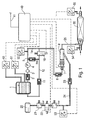
- FIG. 1 one from the DE 199 46 902 known exhaust aftertreatment arrangement
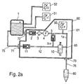
- FIG. 2a a device for reaction-aided exhaust aftertreatment without compressed air assistance with a delivery module
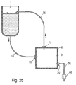
- FIG. 2b a schematic representation of an exhaust aftertreatment device
- FIG. 3 another device for exhaust aftertreatment
- FIG. 4 a device with an alternative delivery module
- FIG. 5 a flow chart
- FIG. 6 a further device for compressed air metered metered reagent introduction into the exhaust tract with means for blowing out the reagent.
- FIG. 1 a device for the aftertreatment of exhaust gases is shown with 1 is a urea tank referred to, from which a urea-water solution via a line 1a, for example, a hose, with a check valve 2 and a filter designed as a filter 3 sucked by a feed pump 4 and over another check valve 6 is conveyed to a metering valve 7.
- the metering valve 7 doses the required amount of urea-water solution in a mixing chamber 8. Any occurring overflow of urea-water Lösüng is via a pressure regulator 5 and another check valve 11 through a return line 12 into the urea tank 1 traceable. Any necessary venting of the line 1a is feasible via a vent circuit with a vent valve 10.
- a compressed air tank referred to, from soft compressed air via a pressure limiter 21, a 2/2-way valve 22 and a check valve 23 can be introduced into the mixing chamber by providing the check valve 23, which, for example, as a ball valve or flat seat valve may be formed, a backflow of a reducing agent-air mixture from the mixing chamber into the compressed air line 24 can be prevented.
- the check valve 23 which, for example, as a ball valve or flat seat valve may be formed
- an aerosol is generated by pressurizing the urea-water solution by means of the compressed air, which is introduced via an aerosol line 25 into a catalyst 30.
- a control unit 40 detects signals that are received from a higher-level engine control unit via a CAN data line 41, and the signals from pressure, temperature or level sensors 50 to 55, whose operation is known per se and will not be further explained here Control unit 40 calculates from this information a urea dosing amount which is to be added to an exhaust gas flowing through the catalytic converter 30.
- the control unit 40 regulates the pressure in the compressed air line 24 with the aid of the described solenoid valves and also monitors the urea-water solution pressure.
- the controller 40 detects deviations and errors, stores them and displays them by a diagnostic device (not shown), for example on a PC.
- FIG. 2a shows an apparatus for exhaust aftertreatment, the same components as in the arrangement according to FIG. 1 are marked with the same reference numerals and will not be described again.
- the electrical connections to a control unit 40 are as in the arrangement according to FIG. 1 , are not shown here.
- Check valve 2, filter 3, feed pump 4, pressure regulator 5, pressure sensor 50, line 1a, vent valve 10, return line 12 and the other check valve 11 are structurally integrated in a delivery module ("supply module") 61, which is surrounded by a housing 60.
- the urea tank is in this case connected to the check valve 2 via a connector 72, which connects the line leading away from the tank with the located within the conveyor module, leading to the check valve 2 line la.
- the further check valve 11 is connected in the return line 12 via a further connector 71 with a leading to the urea tank continuation 75 of the return line, for example in the form of a hose connected.
- the line 1a is behind the branch point 65, from which the return line 12 branches off, connected via a further connector 70 with a supply line 76, which leads to a metering valve 80.
- the supply of urea-water solution in the exhaust pipe is carried out without the assistance of compressed air. If the valve 80 is opened, the urea-water solution is injected directly into the exhaust tract without mixing with compressed air.
- the metering valve can be arranged close to the exhaust pipe or it can project its opening directly into the exhaust pipe.
- FIG. 2b schematically again an arrangement with a delivery module 61 is shown with a housing 60 which is connected via three hose connections or connectors 70, 71 and 72 with a tank 1 for a urea-water solution and with the metering valve 80 in connection.
- the delivery module initiates, for example, via a feed pump 4 integrated in it (cf. FIG. 2a suction of urea-water solution from tank 1 via line 1a and connector 72.
- urea-water solution is ready for transfer via connector 70 and supply line 76 to metering valve 80 which, when opened, ensures a supply of urea-water solution in the exhaust system.
- metering valve 80 when the metering valve 80 is closed, a transport of urea-water solution is continued by the delivery module 61.
- the reagent is further sucked in via the line 1a, but returned via the connector 71 and the return hose 75 to the urea tank 1, so that a liquid circulation can be maintained.
- FIG. 3 shows an arrangement with already in FIG. 1 components described in the compressed air assisted to form an aerosol, a urea-water solution is supplied to the exhaust tract.
- non-return valve 2, filter 3, feed pump 4, pressure regulator 5, pressure sensor 50, line 1a, vent valve 10, return line 12 and the other check valve 11 structurally integrated in a delivery module ("supply module") 661, which is surrounded by a housing 660 ,
- supply module a delivery module
- FIG. 2b the line leading to the pump, the return line and the line from the pump connected in the direction of metering valve 7 via respective connectors 672, 671 and 670 connected to the urea tank or the metering valve lines.
- FIG. 4 shows an arrangement with the same components as in FIG. 3 described, in which, however, in addition to the check valve 2, the filter 3, the feed pump 4, the pressure regulator 5, the pressure sensor 50, the line 1a, the vent valve 10, the return line 12 and the other check valve 11 and the components 21 to 24 and 53 are integrated in a conveyor module 761 which is surrounded by a housing 760.
- a method can be performed, as shown schematically in FIG. 5 is shown in the form of a flow chart.
- This method can be implemented in hardware or software in the control unit 40.
- the method step 810 the normal dosing operation, is followed by a query 820 as to whether dosing is still required.
- the query 830 makes a further procedure dependent on the currently prevailing outside temperature.
- Method step 840 includes measures for antifreeze, and query 850 determines whether reagent is to be metered into the exhaust tract again.
- the metering valve 7 or 80 supplies reactants to the exhaust gas tract downstream of the engine. This is constantly queried (query 820), whether continued dosing is required or whether may continue to be dosed. For example, it may no longer be metered if the urea tank 1 is no longer sufficiently filled in order to be able to ensure a circulation operation described in more detail below on further withdrawal for the purpose of metering. Even in the case of an error, it is no longer possible to dose it, for example if the catalyst temperature measurement results in implausible values. In addition, it may be provided to monitor the catalyst temperature before the actual start of the metering operation and to start the normal metering operation only when the catalyst is sufficiently warm.
- the temperature of the urea-water solution in the urea tank or alternatively the outside temperature is queried in a further step in query 830. If a certain threshold value is not exceeded (temperature of the urea-water solution below -5 degrees Celsius or outside temperature below -11 degrees Celsius), returns to query 820. However, if the respective temperature threshold value is undershot, measures for antifreeze, which are described in more detail below, are initiated in method step 840. This is constantly queried (query 850), whether to be dosed again. If not, return to query 830, otherwise to method step 810.
- the pump 4 is controlled with the metering valve 7 closed and with the vent valve 10 closed so that it overcomes the threshold value of 3 bar of the pressure regulator 5, so that a circulation circuit of the reaction medium is created which connects the connection plugs 71 and 72 (or 671 and 672) is constantly flushed with reagent.
- the venting valve 10 can be opened and the pump 4 can be switched on or remain so that a circulation circuit can already be provided at a pressure below 3 bar. If these connectors are flushed, a freezing of the reagent, especially outside of the dosing especially at this endangered places can be avoided. These sites are particularly vulnerable to freezing of the reaction medium without special measures, because they have a particularly good cold contact with the environment due to the connection to the housing of the conveyor module.
- the pressure regulating valve 5 can also be replaced by an electrically controllable valve, which assumes the function of a pressure regulating valve in metering operation and can be opened in the case of a closed metering valve to establish a circulation circuit.
- the above-mentioned electrically controllable valve may also be provided in addition to the pressure regulator 5 and connected in parallel thereto.
- further measures can also be provided in order in particular to cover the area of the connector plug 70 (FIG. Fig. 2a ) or 670 ( Fig. 3 ) to protect against freezing of reactants.
- the antifreeze method using a circulation circuit can be continued even after the engine is turned off.
- Embodiment may be waived to query the temperature of the outside air or located in the reactant tank reactant to set up in any case outside the dosing, optionally after switching off the engine, a dosing device or the metering not detected circulation circuit. It may also be provided that the circulation takes place only when or as long as the electrical vehicle electrical system of the motor vehicle of the internal combustion engine has sufficient energy reserves for restarting the internal combustion engine.
- FIG. 6 illustrates a further development of a system according to FIG. 2a for the pressureless injection of reactant, in particular a urea-water solution, into the exhaust gas tract.
- the delivery module 960 in contrast to the delivery module 60 according to FIG. 2a
- a switching valve 962 and a compressed air line 973 which connects the switching valve with a compressed air connector 971.
- the changeover valve connects (via the electrical control unit, not shown, controllable) the connector 70 and the metering valve 80 selectively connected to the pump 4 line 1a or with the connector 971.
- the delivery module 960 via a further compressed air line 972 connected to an electrically controllable compressed air supply device 970, which can also be controlled via said el. Control unit.
- This Druck Kunststoffchtfiihr includes, for example, a compressed air cartridge and a means for metering the compressed air, in particular an electrically controllable compressed air valve.
- the means for metering the compressed air can also be fed by a compressed air source already located on board the motor vehicle with compressed air, for example coming from a pressure accumulator or pressure controlled directly from a compressor.
- FIG. 6 An arrangement after FIG. 6 allows in addition to a device of a circulation circuit for anti-freeze of the connector 71 and 72, as in the description of FIG. 5
- a measure for the antifreeze of the connector plug 70 is explained.
- the connection between the line 1a and the supply line 76 is disconnected by means of the switching valve 962, and it is, as in the FIG. 6 shown, the metering valve connected via the compressed air lines 972 and 973 with the compressed air supply device 970.
- the means for metering the compressed air is controlled and still in the supply line 76 or located in the region of the connector plug 70 reactant is in the exhaust system blown out.
- the compressed air supply is turned off, but the switching valve remains in the position described for flushing the metering valve to prevent running of reactant from the line 1a in the region of the connector plug 70. Only when resuming the metering operation, the switching valve is switched again, so that the metering valve can be acted upon again with reagent. Thus, the area of the connector plug 70 is protected from freezing damage.
Landscapes
- Engineering & Computer Science (AREA)
- Chemical & Material Sciences (AREA)
- Chemical Kinetics & Catalysis (AREA)
- Health & Medical Sciences (AREA)
- Environmental & Geological Engineering (AREA)
- Mechanical Engineering (AREA)
- Combustion & Propulsion (AREA)
- General Engineering & Computer Science (AREA)
- Toxicology (AREA)
- Biomedical Technology (AREA)
- Analytical Chemistry (AREA)
- General Chemical & Material Sciences (AREA)
- Oil, Petroleum & Natural Gas (AREA)
- Exhaust Gas After Treatment (AREA)
Description
- Die Erfindung geht aus von einem Verfahren bzw. einer Vorrichtung zum Nachbehandeln von Abgasen einer Brennkraftmaschine nach der Gattung der unabhängigen Ansprüche.
- Es ist schon aus der
DE 199 46 902 A1 bekannt, eine Hamstoff-Wasser-Lösung zur Abgasentstickung nachmotorisch in den Abgastrakt einzubringen und dabei eine Rückflußleitung von einer Förderpumpe zurück zu einem Hamstofftank vorzusehen, die zum Abbau eines eventuell vorhandenen Überdrucks in der Hamstoffleitung beziehungsweise zur Entlüftung der Hamstoffleitung eingesetzt wird, bei der jedoch insbesondere in gefrierkritischen Situationen, insbesondere außerhalb von Zeiten, in denen das Reduktionsmittel in den Abgastrakt eindosiert wird, kein kontinuierlicher Wärmeaustausch zwischen der Hamstoff-Wasser-Lösung und gefriergefährdeten Stellen der Abgasnachbehandlungsvorrichtung vorgesehen ist - Weiterhin ist aus der
DE 102 54 981 A1 bekannt, aus reduktionsmittelführenden Leitungen dort noch enthaltenes Reduktionsmittel nach der Dosierung mittels Druckluft zu entfernen. - Die
US 2004/0098978 A1 beschreibt eine Zirkulation eines Reduktionsmittels durch einen Injektor. - Das erfindungsgemäße Verfahren beziehungsweise die erfindungsgemäße Vorrichtung mit den kennzeichnenden Merkmalen der unabhängigen Ansprüche haben demgegenüber den Vorteil, eine einfache, platzsparende und effektive Alternative zum Gefrierschutz einer Abgasnachbehandlungsvorrichtung bereitzustellen, die auf mechanischer Seite weitgehend mit bereits vorhandenen Installationen realisiert und in einfacher Weise softwaremässig implementiert werden kann. Insbesondere auch bei kleineren Dosiermengen und bei kaltem Fahrtwand stellt eine Reaktionsmittelzirkulation einen guten Schutz vor einem Eingefrieren dar. Dabei ist es vorteilhaft, eine Zirkulation in einem Fordermodul vorzusehen, das über eine Zufuhrleitung mit einer Dosiervonichtung verbunden ist. Hierdurch wird auf kleinem Raum ein effektiver Gefrierschutz insbesondere an Verbindungsbereichen bzw. Verbindungssteckern gewährleistet, die Verbindungen zum Reaktionsmittelbebälter herstellen. Des weiteren ist es energiesparend, einen Zirkulationsbetrieb nur dann vorzusehen, wenn ein gewisser Temperaturschwellenwert unterschritten wird, ab dem die Gefahr besteht, dass an Bord befindliches flüssiges Reaktionsmittel an gefriergefahrdeten Stellen einfriert.
- Durch die in den abhängigen Ansprüchen aufgeführten Maßnahmen sind vorteilhafte Weiterbildungen und Verbesserungen des im unabhängigen Anspruch angegebenen Verfahrens beziehungsweise der angegebenenVorrichtung zur Abgasnachbehandlung möglich.
- Vorteilhaft ist es ferner, insbesondere außerhalb des Dosierbetriebs und/oder bei ausgeschalteter Brennkraftmaschine eine Reaktionsmittelzirkulation zu veranlassen, so dass der eigentliche Dosierbetrieb nicht durch eventuell aufgrund des Zirkulationsbetriebs entstehenden Druckschwankungen in den Leitungen gestört wird bzw. auch parkendem Fahrzeug ein Gefrierschutz gewährleistet ist.
- Vorteilhaft ist es ferner, einen Schutz vor einer Entladung der Bordbatterie vorzusehen, um zu jedem Zeitpunkt ein Wiederanlassen der Brennkraftmaschine sicherzustellen.
- Ausführungsbeispiele der Erfindung sind in der Zeichnung dargestellt und in der nachfolgenden Beschreibung näher erläutert. Es zeigen
Figur 1 eine aus derDE 199 46 902 bekannte Abgasnachbehandlungsanordnung,Figur 2a eine Vorrichtung zur reaktionsmittelgestützten Abgasnachbehandlung ohne Druckluftunterstützung mit einem Fördermodul,Figur 2b eine schematische Darstellung einer Abgasnachbehandlungsvorrichtung,Figur 3 eine weitere Vorrichtung zur Abgasnachbehandlung,Figur 4 eine Vorrichtung mit einem alternativen Fördermodul,Figur 5 ein Flussdiagramm undFigur 6 eine weitere Vorrichtung zur druckluftlosen dosierten Reaktionsmitteleinbringung in den Abgastrakt mit Mitteln zum Ausblasen des Reaktionsmittels. - In
Figur 1 ist eine Vorrichtung zur Nachbehandlung von Abgasen dargestellt Mit 1 ist ein Harnstofftank bezeichnet, aus welchem eine Hamstoff-Wasser-Lösung über eine Leitung 1a, beispielsweise eine Schlauchleitung, mit einem Rückschlagventil 2 und einem als Filtersieb ausgeführten Filter 3 von einer Förderpumpe 4 angesaugt und über ein weiteres Rückschlagventil 6 zu einem Dosierventil 7 gefördert wird. Das Dosierventil 7 dosiert die erforderliche Menge an Hamstoff-Wasser-Lösung in eine Mischkammer 8. Eine eventuell auftretende Überströmmenge der Hamstoff-Wasser-Lösüng ist über einen Druckregler 5 und ein weiteres Rückschlagventil 11 durch eine Rücklaufleitung 12 in den Harnstofftank 1 zurückführbar. Eine eventuell notwendige Entlüftung der Leitung 1a ist über einen Entlüftungskreislauf mit einem Entlüftungsventil 10 durchführbar. Mit 20 ist ferner ein Druckluftbehälter bezeichnet, aus weichem Druckluft über einen Druckbegrenzer 21, ein 2/2-Wegeventil 22 und ein Rückschlagventil 23 in die Mischkammer einbringbar ist Durch Vorsehen des Rückschlagventils 23, welches beispielsweise als Kugelventil oder Flachsitzventil ausgebildet sein kann, kann ein Rückströmen eines Reduktionsmittel-Luft-Gemisches aus der Mischkammer in die Druckluftleitung 24 hinaus verhindert werden. Hierdurch ist die Gefahr einer Kontamination eines mit der Druckluftleitung 24 kommunizierenden Druckluft-Bordnetzes gegenüber herkömmlichen Systemen stark reduziert. - In der Mischkammer 8 wird unter Beaufschlagung der Harnstoff-Wasser-Lösung mittels der Druckluft ein Aerosol erzeugt, welches über eine Aerosolleitung 25 in einen Katalysator 30 eingebracht wird. Ein Steuergerät 40 erfaßt hierbei Signale, die von einem übergeordneten Motorsteuergerät über eine CAN-Datenleitung 41 empfangen werden, sowie die Signale von Druck-, Temperatur- bzw. Füllstandssensoren 50 bis 55, deren Funktionsweise an sich bekannt ist und hier nicht weiter erläutert wird Das Steuergerät 40 berechnet aus diesen Informationen eine Harnstoff-Dosiermenge, welche einem den Katalysator 30 durchströmenden Abgas zugegeben werden soll.
- Das Steuergerät 40 regelt mit Hilfe der beschriebenen Magnetventile den Druck in der Druckluftleitung 24 und überwacht ferner den Hamstoff-Wasser-Lösungsdruck. Das Steuergerät 40 erkennt Abweichungen und Fehler, speichert diese und bringt sie durch ein (nicht gezeigtes) Diagnosegerät, beispielsweise an einem PC, zur Anzeige.
-
Figur 2a zeigt eine Vorrichtung zur Abgasnachbehandlung, bei der gleiche Bestandteile wie bei der Anordnung nachFigur 1 mit gleichen Bezugszeichen markiert sind und nicht nochmals beschrieben werden. Die elektrischen Verbindungen zu einem Steuergerät 40 bestehen wie bei der Anordnung nachFigur 1 , sind hier jedoch nicht dargestellt. Rückschlagventil 2, Filter 3, Förderpumpe 4, Druckregler 5, Drucksensor 50, Leitung 1a, Entlüftungsventil 10, Rücklaufleitung 12 und das weitere Rückschlagventil 11 sind baulich in einem Fördermodul ("supply module") 61 integriert, das von einem Gehäuse 60 umgeben ist. Der Harnstofftank ist hierbei mit dem Rückschlagventil 2 über einen Verbindungsstecker 72 verbunden, der die vom Tank wegführende Leitung mit der sich innerhalb des Fördermoduls befindlichen, zum Rückschlagventil 2 führenden Leitung la zusammenschließt. In ähnlicher Weise ist das weitere Rückschlagventil 11 in der Rücklaufleitung 12 über einen weiteren Verbindungsstecker 71 mit einer zum Harnstofftank führenden Fortsetzung 75 der Rücklaufleitung, beispielsweise in Form eines Schlauches, verbunden. Die Leitung 1a ist hinter dem Abzweigungspunkt 65, von dem aus die Rücklaufleitung 12 abzweigt, über einen weiteren Verbindungsstecker 70 mit einer Zufuhrleitung 76 zusammengeschlossen, die zu einem Dosierventil 80 führt. - Im Unterschied zur Anordnung nach
Figur 1 erfolgt die Zuführung der Harnstoff-Wasser-Lösung in die Abgasleitung ohne Unterstützung durch Druckluft. Ist das Ventil 80 geöffnet, wird direkt die Harnstoff-Wasser-Lösung ohne Vermischung mit Druckluft in den Abgastrakt eingespritzt. Hierzu kann das Dosierventil nahe der Abgasleitung angeordnet werden bzw. es kann dessen Öffnung unmittelbar in die Abgasleitung hineinragen. - In
Figur 2b ist nochmals schematisch eine Anordnung mit einem Fördermodul 61 mit einem Gehäuse 60 dargestellt, das über drei Schlauchverbindungen bzw. Verbindungsstecker 70, 71 und 72 mit einem Tank 1 für eine Harnstoff-Wasser-Lösung sowie mit dem Dosierventil 80 in Verbindung steht. - Das Fördermodul veranlasst beispielsweise über eine in ihr integrierte Förderpumpe 4 (vgl.
Figur 2a ) ein Ansaugen von Harnstoff-Wasser-Lösung aus dem Tank 1 über die Leitung 1a und den Verbindungsstecker 72. Dadurch steht Harnstoff-Wasser-Lösung zur Weiterleitung über Verbindungsstecker 70 und Zufuhrleitung 76 an das Dosierventil 80 bereit, das, wenn es geöffnet wird, eine Zufuhr von Harnstoff-Wasser-Lösung in den Abgastrakt gewährleistet. Insbesondere dann, wenn das Dosierventil 80 geschlossen ist, wird durch das Fördermodul 61 ein Transport von Harnstoff-Wasser-Lösung fortgeführt. Dabei wird das Reaktionsmittel über die Leitung 1a weiterhin angesaugt, aber über den Verbindungsstecker 71 und den Rückfluß-Schlauch 75 zum Harnstofftank 1 zurückgeführt, so dass eine Flüssigkeitszirkulation aufrechterhalten werden kann. -
Figur 3 zeigt eine Anordnung mit bereits inFigur 1 beschriebenen Bestandteilen, bei der druckluftunterstützt unter Bildung eines Aerosols eine Harnstoff-Wasser-Lösung dem Abgastrakt zugeführt wird. Hierbei sind Rückschlagventil 2, Filter 3, Förderpumpe 4, Druckregler 5, Drucksensor 50, Leitung 1a, Entlüftungsventil 10, Rücklaufleitung 12 und das weitere Rückschlagventil 11 baulich in einem Fördermodul ("supply module") 661 integriert, das von einem Gehäuse 660 umgeben ist. Dabei sind in ähnlicher Weise zum Aufbau nachFigur 2b die zur Pumpe führende Leitung, die Rücklaufleitung und die Leitung von der Pumpe in Richtung Dosierventil 7 über jeweilige Verbindungsstecker 672, 671 und 670 mit mit dem Harnstofflank bzw. dem Dosierventil verbundenen Leitungen zusammengeschlossen. -
Figur 4 zeigt eine Anordnung mit gleichen Bauteilen wie inFigur 3 beschrieben, bei der jedoch zusätzlich zu dem Rückschlagventil 2, dem Filter 3, der Förderpumpe 4, dem Druckregler 5, dem Drucksensor 50, der Leitung 1a, dem Entlüftungsventil 10, der Rücklaufleitung 12 und dem weiteren Rückschlagventil 11 auch die Bauteile 21 bis 24 und 53 in einem Fördermodul 761 integriert sind, das von einem Gehäuse 760 umgeben ist. - Mit den in
Figur 2a bis 4 beschriebenen Vorrichtungen, also sowohl bei druckluftunterstützten Reaktionsmitteleinspritzungen als auch bei druckluftlosen Einspritzungen, kann ein Verfahren durchgeführt werden, wie es schematisch inFigur 5 in Form eines Flussdiagramms dargestellt ist. Dieses Verfahren kann hardwaremässig oder softwaremässig im Steuergerät 40 implementiert sein. Dem Verfahrensschritt 810, dem normalen Dosierbetrieb, folgt eine Abfrage 820, ob weiterhin Dosierbedarf besteht. Die Abfrage 830 macht ein weiteres Vorgehen von der momentan herrschenden Außentemperatur abhängig. Verfahrensschritt 840 umfaßt Maßnahmen zum Gefrierschutz, und die Abfrage 850 stellt fest, ob wieder Reaktionsmittel in den Abgastrakt dosiert werden soll. - Beim normalen Dosierbetrieb (Verfahrensschritt 810) wird über das Dosierventil 7 bzw. 80 Reaktionsmittel nachmotorisch dem Abgastrakt zugeführt. Hierbei wird ständig abgefragt (Abfrage 820), ob weiterhin Dosierbedarf besteht bzw. ob weiterhin dosiert werden darf. Dosiert werden darf beispielsweise dann nicht mehr, wenn der Harnstofftank 1 nicht mehr hinreichend gefüllt ist, um bei weiterer Entnahme zwecks Dosierung noch einen weiter unten näher beschriebenen Zirkulationsbetrieb sicherstellen zu können. Auch in einem Fehlerfall darf nicht mehr dosiert werden, zum Beispiel wenn die Katalysatortemperaturmessung unplausible Werte ergibt. Zusätzlich kann vorgesehen sein, vor dem eigentlichen Start des Dosierbetriebs die Katalysatortemperatur zu überwachen und den normalen Dosierbetrieb erst zu starten, wenn der Katalysator hinreichend warm ist. Falls kein Dosierbedarf mehr besteht oder falls nicht mehr dosiert werden darf, wird in einem weiteren Schritt in Abfrage 830 die Temperatur der Harnstoff-Wasser-Lösung im Harnstofftank oder alternativ die Außentemperatur abgefragt. Falls ein bestimmter Schwellenwert nicht unterschritten wird (Temperatur der Harnstoff-Wasser-Lösung unterhalb von - 5 Grad Celsius bzw. Außentemperatur unterhalb von - 11 Grad Celsius), wird zur Abfrage 820 zurückgekehrt. Wird jedoch der betreffende TemperaturSchwellenwert unterschritten, werden im Verfahrensschritt 840 nachfolgend näher beschriebene Maßnahmen zum Gefrierschutz eingeleitet. Hierbei wird ständig abgefragt (Abfrage 850), ob wieder dosiert werden soll. Falls nein, wird zur Abfrage 830 zurückgesprungen, ansonsten zu Verfahrensschritt 810.
- Bei der Anordnung gemäß
Figur 2a bzw. 3 wird hierbei die Pumpe 4 bei geschlossenem Dosierventil 7 und bei geschlossenem Entlüftungsventil 10 so angesteuert, dass sie den Schwellenwert von 3 bar des Druckreglers 5 überwindet, so dass ein Zirkulationskreislauf des Reaktionsmittels entsteht, der die Verbindungsstecker 71 und 72 (bzw. 671 und 672) ständig mit Reaktionsmittel durchspült. - Alternativ kann bei geschlossenem Dosierventil das Entlüftungsventil 10 geöffnet und die Pumpe 4 angeschaltet werden bzw. bleiben, so dass bereits bei einem Druck unterhalb von 3 bar ein Zirkulationskreislauf bereitgestellt werden kann. Werden diese Verbindungsstecker durchspült, kann ein Eingefrieren des Reaktionsmittels insbesondere außerhalb des Dosierbetriebs gerade auch an diesen hierfür gefährdeten Stellen vermieden werden. Diese Stellen sind ohne besondere Maßnahmen zum Gefrierschutz besonders anfällig für das Eingefrieren des Reaktionsmittels, weil diese aufgrund der Verbindung zum Gehäuse des Fördermoduls einen besonders guten Kältekontakt zur Umgebung aufweisen. Alternativ kann das Druckregelventil 5 auch durch ein elektrisch ansteuerbares Ventil ersetzt werden, das im Dosierbetrieb die Funktion eines Druckregelventils übernimmt und im Falle eines geschlossenen Dosierventils zur Einrichtung eines Zirkulationskreislaufs geöffnet werden kann. Alternativ kann das soeben genannte elektrisch ansteuerbare Ventil auch zusätzlich zum Druckregler 5 vorgesehen und zu diesem parallel geschaltet sein. Zusätzlich zur Einrichtung eines Zirkulationskreislaufs können auch weitere Maßnahmen vorgesehen sein, um auch insbesondere den Bereich des Verbindungssteckers 70 (
Fig. 2a ) bzw. 670 (Fig. 3 ) vor einem Eingefrieren von Reaktionsmittel zu schützen. Diese fakultativen weiteren Maßnahmen hinsichtlich des Verbindungssteckers 70 bzw. 670 werden anhand der nachfolgendenFigur 6 beschrieben. - Das Gefrierschutzverfahren unter Einsatz eines Zirkulationskreislaufs kann auch nach einem Ausschalten der Brennkraftmaschine fortgesetzt werden. In einer weiteren alternativen Ausführungsform kann darauf verzichtet werden, die Temperatur der Außenluft oder des im Reaktionsmittelbehälter befindlichen Reaktionsmittels abzufragen, um in jedem Fall außerhalb des Dosierbetriebs, wahlweise auch nach Abschalten der Brennkraftmaschine, einen die Dosiervorrichtung bzw. das Dosierventil nicht erfassenden Zirkulationskreislauf einzurichten. Es kann ebenfalls vorgesehen sein, dass die Zirkulation nur dann bzw. solange erfolgt, wenn bzw. wie das elektrische Bordnetz des Kraftfahrzeugs der Brennkraftmaschine hinreichende Energiereserven zum Wiederanlassen der Brennkraftmaschine aufweist.
-
Figur 6 illustriert eine Weiterentwicklung eines Systems gemäßFigur 2a zur druckluftlosen Einspritzung von Reaktionsmittel, insbesondere einer Harnstoff-Wasser-Lösung, in den Abgastrakt. Dabei weist das Fördermodul 960 im Unterschied zum Fördermodul 60 gemäßFigur 2a zusätzlich ein Umschaltventil 962 sowie eine Druckluftleitung 973 auf, die das Umschaltventil mit einem Druckluft-Verbindungsstecker 971 verbindet. Das Umschaltventil verbindet (über das nicht näher dargestellte elektrische Steuergerät ansteuerbar) den Verbindungsstecker 70 bzw. das Dosierventil 80 wahlweise mit der mit der Pumpe 4 verbundenen Leitung 1a oder mit dem Verbindungsstecker 971. An diesem Verbindungsstecker 971 ist das Fördermodul 960 über eine weitere Druckluftleitung 972 an einer elektrisch ansteuerbaren Druckluftzufuhreinrichtung 970 angeschlossen, die ebenfalls über das genannte el. Steuergerät angesteuert werden kann. Diese Druckluftzufiihreinrichtung umfasst beispielsweise eine Druckluftpatrone und ein Mittel zur Dosierung der Druckluft, insbesondere ein elektrisch ansteuerbares Druckluftventil. Alternativ kann das Mittel zur Dosierung der Druckluft auch von einer bereits an Bord des Kraftfahrzeugs befindlichen Druckluftquelle mit Druckluft gespeist werden, beispielsweise von einem Druckspeicher oder druckgeregelt direkt von einem Kompressor kommend. - Eine Anordnung nach
Figur 6 erlaubt neben einer Einrichtung eines Zirkulationskreislaufs zum Gefrierschutz der Verbindungsstecker 71 und 72, wie in der Beschreibung zurFigur 5 erläutert, zusätzlich eine Maßnahme zum Gefrierschutz des Verbindungssteckers 70. Dazu wird die Verbindung zwischen der Leitung 1a und der Zufuhrleitung 76 mittels des Umschaltventils 962 getrennt, und es wird, wie in derFigur 6 dargestellt, das Dosierventil über die Druckluftleitungen 972 und 973 mit der Druckluftzufuhreinrichtung 970 verbunden. Das Mittel zur Dosierung der Druckluft wird angesteuert und noch in der Zufuhrleitung 76 bzw. sich im Bereich des Verbindungssteckers 70 befindliches Reaktionsmittel wird in den Abgastrakt ausgeblasen. Nach einer gewissen Zeit wird die Druckluftzufuhr abgestellt, das Umschaltventil bleibt jedoch in der beschriebenen Stellung zur Spülung des Dosierventils, um ein Nachlaufen von Reaktionsmittel aus der Leitung 1a in den Bereich des Verbindungssteckers 70 zu verhindern. Erst bei Wiederaufnahme des Dosierbetriebs wird das Umschaltventil wieder umgeschaltet, so dass das Dosierventil wieder mit Reaktionsmittel beaufschlagt werden kann. Damit bleibt auch der Bereich des Verbindungssteckers 70 vor Gefrierschäden geschützt.
Claims (9)
- Verfahren zum Nachbehandeln von Abgasen einer Brennkraftmaschine unter Verwendung eines in die Abgase einzubringenden Reaktionsmittels, insbesondere eines Reduktionsmittels, bei dem das Reaktionsmittel mittels einer Fördervorrichtung (4), insbesondere einer Pumpe, aus einem Reaktionsmittelbehälter (1) zu einer Dosiervorrichtung (7; 80), insbesondere einem Dosierventil, gepumpt wird, so dass nach Öffnung der Dosiervorrichtung das Reaktionsmittel dosiert in eine Abgasleitung der Brennkraftmaschine eingebracht werden kann, wobei über eine Rücklaufleitung (12, 75) Reaktionsmittel von der Fördervorrichtung (4) zum Reaktionsmittelbehälter (1) zurückbefördert werden kann, dadurch gekennzeichnet, dass das Reaktionsmittel derart zwischen der Fördervorrichtung (4) und dem Reaktionsmittelbehälter (1) zirkulieren kann, dass insbesondere bei geschlossener Dosiervorrichtung ein Einfrieren des Reaktionsmittels verhindert wird, wobei die Zirkulation zwischen dem Reaktionsmittelbehälter und einem die Fördervorrichtung enthaltenden Fördermodul (61; 661; 761) erfolgt, wobei das Fördermodul über eine nicht von der Zirkulation erfasste Zufuhrleitung (76) mit der Dosiervorrichtung (7; 80) verbunden ist, und wobei die Zirkulation nur erfolgt, wenn die Temperatur der Außenluft oder des im Reaktionsmittelbehälter befindlichen Reaktionsmittels einen Schwellenwert unterschreitet (830).
- Verfahren nach Anspruch 1, dadurch gekennzeichnet, dass die Zirkulation kontinuierlich erfolgt.
- Verfahren nach Anspruch 1 oder 2, dadurch gekennzeichnet, dass im Anschluß an einen Dosierbetrieb die Zufuhrleitung (76) zur Dosiervorrichtung (7; 80) mit einem Gas, insbesondere Druckluft, durchspült wird, um nach der Dosierung in der Zufuhrleitung verbliebenes Reaktionsmittel auszutreiben.
- Verfahren nach einem der vorhergehenden Ansprüche, dadurch gekennzeichnet, dass die Zirkulation zu Zeiten erfolgt, in denen kein Reaktionsmittel in die Abgasleitung eingebracht wird.
- Verfahren nach einem der vorhergehenden Ansprüche, dadurch gekennzeichnet, dass die Zirkulation auch bei ausgeschalteter Brennkraftmaschine erfolgen kann.
- Verfahren nach Anspruch 5, dadurch gekennzeichnet, dass die Zirkulation nur dann bzw. solange erfolgt, wenn bzw. wie das elektrische Bordnetz des Kraftfahrzeugs der Brennkraftmaschine hinreichende Energiereserven zum wederanlassen der Brennkraftmaschine aufweist.
- Verfahren nach einem der vorhergehenden Ansprüche, dadurch gekennzeichnet, dass das Reaktionsmittel ein Reduktionsmittel ist.
- Verfahren nach Anspruch 7, dadurch gekennzeichnet, dass das Reduktionsmittel eine Harnstoff-Wasser-Lösung ist.
- Vorrichtung zum Nachbehandeln von Abgasen einer Brennkraftmaschine unter Verwendung eines in die Abgase einzubringenden Reaktionsmittels, insbesondere eines Reduktionsmittels, eingerichtet mit Mitteln (40) zur Durchführung eines Verfahrens nach einem der vorhergehenden Ansprüche.
Applications Claiming Priority (2)
| Application Number | Priority Date | Filing Date | Title |
|---|---|---|---|
| DE102005002318A DE102005002318A1 (de) | 2005-01-17 | 2005-01-17 | Abgasnachbehandlungsverfahren und Vorrichtung hierzu |
| PCT/EP2005/056050 WO2006074833A1 (de) | 2005-01-17 | 2005-11-18 | Abgasnachbehandlungsverfahren und vorrichtung hierzu |
Publications (2)
| Publication Number | Publication Date |
|---|---|
| EP1841956A1 EP1841956A1 (de) | 2007-10-10 |
| EP1841956B1 true EP1841956B1 (de) | 2008-07-09 |
Family
ID=35559333
Family Applications (1)
| Application Number | Title | Priority Date | Filing Date |
|---|---|---|---|
| EP05817086A Ceased EP1841956B1 (de) | 2005-01-17 | 2005-11-18 | Abgasnachbehandlungsverfahren und vorrichtung hierzu |
Country Status (5)
| Country | Link |
|---|---|
| US (1) | US7775036B2 (de) |
| EP (1) | EP1841956B1 (de) |
| CN (1) | CN101103185B (de) |
| DE (2) | DE102005002318A1 (de) |
| WO (1) | WO2006074833A1 (de) |
Families Citing this family (55)
| Publication number | Priority date | Publication date | Assignee | Title |
|---|---|---|---|---|
| DE102006007554A1 (de) * | 2006-02-16 | 2007-08-23 | Hydraulik-Ring Gmbh | Förderpumpe, insbesondere für Harnstoffwasserlösung als Abgasnachbehandlungsmedium |
| DE102006016447A1 (de) * | 2006-04-07 | 2007-10-11 | Robert Bosch Gmbh | Verfahren zum Betreiben einer Dosiervorrichtung eines Abgas-Reinigungssystems und Vorrichtung zur Durchführung des Verfahrens |
| DE102006019051A1 (de) * | 2006-04-25 | 2007-10-31 | Robert Bosch Gmbh | Vorrichtung zur Zufuhr eines Reduktionsmittels in einen Abgasstrang einer Verbrennungskraftmaschine |
| WO2008048147A1 (en) * | 2006-10-16 | 2008-04-24 | Volvo Lastvagnar Ab | Urea supply system |
| US7954312B2 (en) * | 2007-05-09 | 2011-06-07 | Ford Global Technologies, Llc | Approach for detecting reductant availability and make-up |
| DE102007033470B4 (de) * | 2007-07-18 | 2012-10-25 | Continental Automotive Gmbh | Vorrichtung und Verfahren zur Dosierung eines Reduktionsmittels in einen Abgastrakt eines Fahrzeugs |
| DE102007044403B4 (de) * | 2007-09-18 | 2011-04-28 | Continental Automotive Gmbh | Vorrichtung zum Einbringen einer Reduktionsmittelflüssigkeit in ein Abgas einer Verbrennungsanlage |
| US7976712B2 (en) * | 2007-10-01 | 2011-07-12 | Cummins Filtration Ip, Inc. | Apparatus, system, and method for filtration of a dosing fluid in an exhaust aftertreatment system |
| DE102008013960A1 (de) * | 2008-03-12 | 2009-09-17 | Albonair Gmbh | Dosiersystem zur Eindüsung einer Harnstofflösung in den Abgasstrom eines Verbrennungsmotors |
| CA2721439C (en) * | 2008-04-15 | 2016-01-12 | G.W. Lisk Company, Inc. | System for purging a device |
| DE102008030756A1 (de) | 2008-06-27 | 2010-01-07 | Emitec Gesellschaft Für Emissionstechnologie Mbh | Verfahren zum Betrieb eines HWL-Dosiersystems |
| KR100974599B1 (ko) * | 2008-08-07 | 2010-08-06 | 현대자동차주식회사 | 차량의 요소 분사량 제어장치 및 방법 |
| EP2151559B1 (de) * | 2008-08-08 | 2011-04-06 | Magneti Marelli S.p.A. | Einspritzvorrichtung zum Einspritzen einer Verringerungssubstanz in ein Abgassystem in einem Verbrennungsmotor |
| US8359831B2 (en) * | 2008-10-31 | 2013-01-29 | Ti Group Automotive Systems, L.L.C. | Reactant delivery for engine exhaust gas treatment |
| CN101408122B (zh) * | 2008-11-20 | 2011-05-11 | 张家口百通环保科技有限公司 | 抽取、计量并释放液体的计量输送方法及其装置 |
| US8116961B2 (en) | 2009-06-03 | 2012-02-14 | Ford Global Technologies, Llc | Controlling of a vehicle responsive to reductant conditions |
| DE102009035940C5 (de) * | 2009-08-03 | 2017-04-20 | Cummins Ltd. | SCR-Abgasnachbehandlungseinrichtung |
| DE102009037564B4 (de) * | 2009-08-14 | 2013-08-29 | Continental Automotive Gmbh | Vorrichtung und Verfahren zur Dosierung eines Reduktionsmittels in einen Abgastrakt einer Brennkraftmaschine |
| US8424286B2 (en) | 2009-09-11 | 2013-04-23 | Ford Global Technologies, Llc | Vehicle relocatable exhaust system components |
| DE102010004201A1 (de) * | 2010-01-08 | 2011-07-14 | Emitec Gesellschaft für Emissionstechnologie mbH, 53797 | Verfahren zum Betrieb einer Fördervorrichtung für ein Reduktionsmittel |
| DE102010004615A1 (de) * | 2010-01-13 | 2011-07-14 | Emitec Gesellschaft für Emissionstechnologie mbH, 53797 | Verfahren zur Bestimmung der aus einem Tank entnommenen Menge einer Flüssigkeit |
| DE102010013695A1 (de) * | 2010-04-01 | 2011-10-06 | Emitec Gesellschaft Für Emissionstechnologie Mbh | Verfahren zum Betrieb einer Fördereinheit für ein Reduktionsmittel |
| JP5437890B2 (ja) * | 2010-04-07 | 2014-03-12 | 日野自動車株式会社 | 後処理バーナシステムの燃料凍結防止方法及び装置 |
| SE534974C2 (sv) * | 2010-06-21 | 2012-03-06 | Scania Cv Ab | Förfarande och anordning för att baserat på en doseringsenhets kylbehov bestämma miniminivån i en reduktionsmedelsbehållare i ett SCR-system |
| SE535632C2 (sv) * | 2010-06-21 | 2012-10-23 | Scania Cv Ab | Förfarande vid förekomst av luft i vätsketillförsel vid ett SCR-system och motsvarande SCR-system |
| CN102400742B (zh) * | 2010-09-07 | 2013-12-25 | 博世汽车柴油系统股份有限公司 | 车辆scr系统及其还原剂供应装置 |
| CN101979131A (zh) * | 2010-10-20 | 2011-02-23 | 中国第一汽车集团公司 | 气动式双尿素箱尿素单向阀控制水加热scr尿素系统 |
| AT510671B1 (de) * | 2010-10-29 | 2013-11-15 | Hirtenberger Ag | Vorrichtung zur selektiven katalytischen reduktion von stickoxiden in einem abgastrakt eines kraftfahrzeuges |
| JP5586446B2 (ja) * | 2010-12-16 | 2014-09-10 | Udトラックス株式会社 | エンジンの排気管噴射装置 |
| US9719395B2 (en) * | 2011-05-10 | 2017-08-01 | Albonair Gmbh | Component carrier for a dosing system |
| JP5754865B2 (ja) * | 2011-07-09 | 2015-07-29 | ボッシュ株式会社 | 還元剤供給装置及び内燃機関の排気浄化装置 |
| US8635854B2 (en) * | 2011-08-05 | 2014-01-28 | Tenneco Automotive Operating Company Inc. | Reductant injection control system |
| CN103814195B (zh) | 2011-08-22 | 2017-02-15 | 康明斯排放处理公司 | 尿素喷射系统冲洗循环 |
| DE102011086795A1 (de) | 2011-11-22 | 2013-05-23 | Robert Bosch Gmbh | Vorrichtung zur Kühlung eines Dosierventils |
| US8701389B2 (en) | 2011-12-06 | 2014-04-22 | Tenneco Automotive Operating Company Inc. | Reagent injector control system |
| DE102012002061A1 (de) * | 2012-02-03 | 2013-08-08 | Emitec Gesellschaft Für Emissionstechnologie Mbh | Dosierventil für einfriergefährdete Additive |
| DE102012002059A1 (de) * | 2012-02-03 | 2013-08-08 | Emitec Gesellschaft Für Emissionstechnologie Mbh | Verfahren zum Betrieb einer Dosiervorrichtung |
| DE102012212558B4 (de) | 2012-07-18 | 2025-11-20 | Robert Bosch Gmbh | Verfahren zum Befüllen und Entlüften von trockenen Komponenten eines Förder- und Dosiersystems |
| DE102012212559B4 (de) | 2012-07-18 | 2025-12-24 | Robert Bosch Gmbh | Verfahren zum Betreiben eines Förder- und Dosiersystems |
| CN102996529B (zh) * | 2012-11-20 | 2016-04-13 | 武汉芙源生环保技术有限公司 | 内燃机尾气净化后处理系统的压缩空气驱动的计量装置 |
| US9222388B2 (en) * | 2013-02-28 | 2015-12-29 | Tenneco Automotive Operating Company Inc. | Urea common rail |
| CN103291423B (zh) * | 2013-06-13 | 2015-05-20 | 中国第一汽车股份有限公司无锡油泵油嘴研究所 | 一种还原剂供给装置 |
| DE102014202038B4 (de) * | 2014-02-05 | 2024-12-12 | Robert Bosch Gmbh | Verfahren zum Betreiben eines Förder- und Dosiersystems |
| US20150023843A1 (en) * | 2014-10-09 | 2015-01-22 | Caterpillar Inc. | Reductant supply system |
| DE102014220983A1 (de) * | 2014-10-16 | 2016-04-21 | Robert Bosch Gmbh | Reagenzmittel-Dosiersystem |
| SE539206C2 (en) | 2014-12-16 | 2017-05-09 | Scania Cv Ab | A method for feeding a fluid and a flexible hose, primarily intended for transporting fluid / urea in a vehicle in cold weather |
| JP6445476B2 (ja) * | 2016-01-29 | 2018-12-26 | 日立建機株式会社 | 建設機械 |
| CN106089379B (zh) * | 2016-06-07 | 2019-08-30 | 无锡威孚高科技集团股份有限公司 | 基于工况判断及模块化的scr后处理集成控制系统及方法 |
| EP3324014A1 (de) * | 2016-11-22 | 2018-05-23 | Volvo Truck Corporation | Anordnung für ein abgasnachbehandlungssystem |
| EP3333386B1 (de) * | 2016-12-12 | 2019-08-28 | Perkins Engines Company Limited | Injektorablagerungsauflösungssystem und -verfahren |
| DE102017217891A1 (de) * | 2017-10-09 | 2019-04-11 | Robert Bosch Gmbh | Fördermodul zur Förderung eines Fluids |
| US10641152B2 (en) * | 2017-12-04 | 2020-05-05 | Caterpillar Inc. | Control system for a reductant dosing system |
| DE102017222471A1 (de) | 2017-12-12 | 2019-06-13 | Robert Bosch Gmbh | Anordnung zur Bevorratung eines gefrierfähigen Fluids |
| US11040308B2 (en) | 2018-07-05 | 2021-06-22 | Cummins Emission Solutions Inc. | Systems and methods for purging reductant from a reductant injector |
| DE102021206351B4 (de) | 2021-06-21 | 2026-02-05 | Volkswagen Aktiengesellschaft | Verfahren zur Abgasnachbehandlung eines Verbrennungsmotors und Abgasnachbehandlungssystem |
Family Cites Families (13)
| Publication number | Priority date | Publication date | Assignee | Title |
|---|---|---|---|---|
| US5522218A (en) * | 1994-08-23 | 1996-06-04 | Caterpillar Inc. | Combustion exhaust purification system and method |
| WO1996008639A1 (de) * | 1994-09-13 | 1996-03-21 | Siemens Aktiengesellschaft | Verfahren und einrichtung zum einbringen von flüssigkeit in eine abgasreinigungsvorrichtung |
| US5968464A (en) * | 1997-05-12 | 1999-10-19 | Clean Diesel Technologies, Inc. | Urea pyrolysis chamber and process for reducing lean-burn engine NOx emissions by selective catalytic reduction |
| US6273120B1 (en) * | 1998-11-12 | 2001-08-14 | Siemens Aktiengesellschaft | Device for introducing a liquid reducing agent into an exhaust gas purification system |
| JP2003529011A (ja) * | 1999-06-09 | 2003-09-30 | クリーン ディーゼル テクノロジーズ インコーポレーテッド | 選択的接触還元による、エンジンからのNOx排気の減少を保証するための方法及び組成物 |
| DE19933798C2 (de) * | 1999-07-19 | 2001-06-21 | Siemens Ag | Vorrichtung und Verfahren zur Abgasnachbehandlung bei einer Brennkraftmaschine |
| DE10139142A1 (de) | 2001-08-09 | 2003-02-20 | Bosch Gmbh Robert | Abgasbehandlungseinheit und Messvorrichtung zur Ermittlung einer Konzentration einer Harnstoff-Wasser-Lösung |
| US6810661B2 (en) * | 2002-08-09 | 2004-11-02 | Ford Global Technologies, Llc | Method and system for freeze protecting liquid NOx reductants for vehicle application |
| DE10251588A1 (de) * | 2002-11-06 | 2004-05-19 | Robert Bosch Gmbh | Vorrichtung zur Nachbehandlung des Abgases einer Brennkraftmaschine |
| US6941746B2 (en) * | 2002-11-21 | 2005-09-13 | Combustion Components Associates, Inc. | Mobile diesel selective catalytic reduction systems and methods |
| JP3751962B2 (ja) | 2003-09-05 | 2006-03-08 | 日産ディーゼル工業株式会社 | エンジンの排気浄化装置 |
| US7594393B2 (en) * | 2004-09-07 | 2009-09-29 | Robert Bosch Gmbh | Apparatus for introducing a reducing agent into the exhaust of an internal combustion engine |
| FR2879239A1 (fr) * | 2004-12-15 | 2006-06-16 | Inergy Automotive Systems Res | Systeme de stockage et d'injection d'un additif dans des gaz d'echappement d'un moteur |
-
2005
- 2005-01-17 DE DE102005002318A patent/DE102005002318A1/de not_active Withdrawn
- 2005-11-18 EP EP05817086A patent/EP1841956B1/de not_active Ceased
- 2005-11-18 CN CN2005800467605A patent/CN101103185B/zh not_active Expired - Fee Related
- 2005-11-18 WO PCT/EP2005/056050 patent/WO2006074833A1/de not_active Ceased
- 2005-11-18 US US11/721,194 patent/US7775036B2/en not_active Expired - Fee Related
- 2005-11-18 DE DE502005004687T patent/DE502005004687D1/de not_active Expired - Lifetime
Also Published As
| Publication number | Publication date |
|---|---|
| EP1841956A1 (de) | 2007-10-10 |
| CN101103185A (zh) | 2008-01-09 |
| CN101103185B (zh) | 2011-08-31 |
| WO2006074833A1 (de) | 2006-07-20 |
| DE102005002318A1 (de) | 2006-07-27 |
| DE502005004687D1 (de) | 2008-08-21 |
| US20090255232A1 (en) | 2009-10-15 |
| US7775036B2 (en) | 2010-08-17 |
Similar Documents
| Publication | Publication Date | Title |
|---|---|---|
| EP1841956A1 (de) | Abgasnachbehandlungsverfahren und vorrichtung hierzu | |
| EP2094953B1 (de) | Vorrichtung zum dosieren eines flüssigen reduktionsmittels | |
| DE102009037564B4 (de) | Vorrichtung und Verfahren zur Dosierung eines Reduktionsmittels in einen Abgastrakt einer Brennkraftmaschine | |
| EP2094954B1 (de) | Dosiervorrichtung für flüssig-reduktionsmittel | |
| EP2791481B1 (de) | Dosieranordnung für ein flüssiges abgasnachbehandlungsmittel und dosierverfahren | |
| EP2126298B1 (de) | Vorrichtung zum dosieren eines reduktionsmittels | |
| DE102015223475A1 (de) | Abgasreinigungsvorrichtung einer Brennkraftmaschine | |
| DE112011104219B4 (de) | Reagenzbehälternormalisierungssystem | |
| WO2009121644A1 (de) | Vorrichtung zum dosieren eines flüssigen reduktionsmittels | |
| DE102011076429A1 (de) | Dosiersystem und Verfahren zu seinem Betrieb | |
| DE102007033470B4 (de) | Vorrichtung und Verfahren zur Dosierung eines Reduktionsmittels in einen Abgastrakt eines Fahrzeugs | |
| DE102006019051A1 (de) | Vorrichtung zur Zufuhr eines Reduktionsmittels in einen Abgasstrang einer Verbrennungskraftmaschine | |
| EP1761690B1 (de) | Dosierventilanordnung sowie verfahren zum betreiben einer dosierventilanordnung | |
| EP2669484A2 (de) | Einspritzsystem, Abgasnachbehandlungseinrichtung | |
| DE102009011018A1 (de) | Vorrichtung zum Zuführen eines Hilfsmittels zu einer Abgasnachbehandlungseinrichtung eines Kraftfahrzeugs | |
| DE102008043405B4 (de) | Verfahren zur Prüfung der Funktionsfähigkeit einer Pumpe | |
| DE102015208565A1 (de) | Hydraulisches Förder- und Dosiersystem und Verfahren zum Betreiben des hydraulischen Förder- und Dosiersystems | |
| WO2008080477A1 (de) | Dosiersystem und verfahren zum betreiben eines dosiersystems | |
| DE102011087288A1 (de) | Abgasnachbehandlungssystem und Verfahren zum Einbringen eines Reduktionsmittels in einen Abgaskanal einer Brennkraftmaschine | |
| DE102010039103A1 (de) | Dosiersystem sowie 3/2-Wegeventil für ein Dosiersystem | |
| EP3212906B1 (de) | Fördereinheit zur förderung einer flüssigkeit | |
| DE102018111474B4 (de) | Fluidsystem und Verwendung eines bidirektionalen Druckventils | |
| WO2011086023A1 (de) | Vorrichtung mit einem injektor für ein flüssiges reduktionsmittel | |
| DE102014226476A1 (de) | Absperrventil für ein Dosiermodul und Verfahren zu seiner Diagnose | |
| DE102011086022A1 (de) | Fördermodul |
Legal Events
| Date | Code | Title | Description |
|---|---|---|---|
| PUAI | Public reference made under article 153(3) epc to a published international application that has entered the european phase |
Free format text: ORIGINAL CODE: 0009012 |
|
| 17P | Request for examination filed |
Effective date: 20070817 |
|
| AK | Designated contracting states |
Kind code of ref document: A1 Designated state(s): DE FR IT SE |
|
| 17Q | First examination report despatched |
Effective date: 20071109 |
|
| GRAP | Despatch of communication of intention to grant a patent |
Free format text: ORIGINAL CODE: EPIDOSNIGR1 |
|
| DAX | Request for extension of the european patent (deleted) | ||
| RBV | Designated contracting states (corrected) |
Designated state(s): DE FR IT SE |
|
| GRAS | Grant fee paid |
Free format text: ORIGINAL CODE: EPIDOSNIGR3 |
|
| GRAA | (expected) grant |
Free format text: ORIGINAL CODE: 0009210 |
|
| AK | Designated contracting states |
Kind code of ref document: B1 Designated state(s): DE FR IT SE |
|
| REF | Corresponds to: |
Ref document number: 502005004687 Country of ref document: DE Date of ref document: 20080821 Kind code of ref document: P |
|
| REG | Reference to a national code |
Ref country code: SE Ref legal event code: TRGR |
|
| PLBE | No opposition filed within time limit |
Free format text: ORIGINAL CODE: 0009261 |
|
| STAA | Information on the status of an ep patent application or granted ep patent |
Free format text: STATUS: NO OPPOSITION FILED WITHIN TIME LIMIT |
|
| 26N | No opposition filed |
Effective date: 20090414 |
|
| PGFP | Annual fee paid to national office [announced via postgrant information from national office to epo] |
Ref country code: IT Payment date: 20101126 Year of fee payment: 6 |
|
| PGFP | Annual fee paid to national office [announced via postgrant information from national office to epo] |
Ref country code: SE Payment date: 20111122 Year of fee payment: 7 |
|
| PG25 | Lapsed in a contracting state [announced via postgrant information from national office to epo] |
Ref country code: SE Free format text: LAPSE BECAUSE OF NON-PAYMENT OF DUE FEES Effective date: 20121119 |
|
| PG25 | Lapsed in a contracting state [announced via postgrant information from national office to epo] |
Ref country code: IT Free format text: LAPSE BECAUSE OF NON-PAYMENT OF DUE FEES Effective date: 20121118 |
|
| REG | Reference to a national code |
Ref country code: FR Ref legal event code: PLFP Year of fee payment: 11 |
|
| REG | Reference to a national code |
Ref country code: FR Ref legal event code: PLFP Year of fee payment: 12 |
|
| REG | Reference to a national code |
Ref country code: FR Ref legal event code: PLFP Year of fee payment: 13 |
|
| PGFP | Annual fee paid to national office [announced via postgrant information from national office to epo] |
Ref country code: FR Payment date: 20221118 Year of fee payment: 18 |
|
| PGFP | Annual fee paid to national office [announced via postgrant information from national office to epo] |
Ref country code: DE Payment date: 20230124 Year of fee payment: 18 |
|
| REG | Reference to a national code |
Ref country code: DE Ref legal event code: R119 Ref document number: 502005004687 Country of ref document: DE |
|
| PG25 | Lapsed in a contracting state [announced via postgrant information from national office to epo] |
Ref country code: DE Free format text: LAPSE BECAUSE OF NON-PAYMENT OF DUE FEES Effective date: 20240601 |
|
| PG25 | Lapsed in a contracting state [announced via postgrant information from national office to epo] |
Ref country code: FR Free format text: LAPSE BECAUSE OF NON-PAYMENT OF DUE FEES Effective date: 20231130 |
|
| PG25 | Lapsed in a contracting state [announced via postgrant information from national office to epo] |
Ref country code: FR Free format text: LAPSE BECAUSE OF NON-PAYMENT OF DUE FEES Effective date: 20231130 Ref country code: DE Free format text: LAPSE BECAUSE OF NON-PAYMENT OF DUE FEES Effective date: 20240601 |