EP1840999A2 - Solid electrolyte fuel cell and process for the production thereof - Google Patents
Solid electrolyte fuel cell and process for the production thereof Download PDFInfo
- Publication number
- EP1840999A2 EP1840999A2 EP07006699A EP07006699A EP1840999A2 EP 1840999 A2 EP1840999 A2 EP 1840999A2 EP 07006699 A EP07006699 A EP 07006699A EP 07006699 A EP07006699 A EP 07006699A EP 1840999 A2 EP1840999 A2 EP 1840999A2
- Authority
- EP
- European Patent Office
- Prior art keywords
- solid electrolyte
- layer
- cathode
- fuel cell
- cathode layer
- Prior art date
- Legal status (The legal status is an assumption and is not a legal conclusion. Google has not performed a legal analysis and makes no representation as to the accuracy of the status listed.)
- Granted
Links
Images


Classifications
-
- H—ELECTRICITY
- H01—ELECTRIC ELEMENTS
- H01M—PROCESSES OR MEANS, e.g. BATTERIES, FOR THE DIRECT CONVERSION OF CHEMICAL ENERGY INTO ELECTRICAL ENERGY
- H01M4/00—Electrodes
- H01M4/86—Inert electrodes with catalytic activity, e.g. for fuel cells
- H01M4/8647—Inert electrodes with catalytic activity, e.g. for fuel cells consisting of more than one material, e.g. consisting of composites
- H01M4/8657—Inert electrodes with catalytic activity, e.g. for fuel cells consisting of more than one material, e.g. consisting of composites layered
-
- H—ELECTRICITY
- H01—ELECTRIC ELEMENTS
- H01M—PROCESSES OR MEANS, e.g. BATTERIES, FOR THE DIRECT CONVERSION OF CHEMICAL ENERGY INTO ELECTRICAL ENERGY
- H01M4/00—Electrodes
- H01M4/86—Inert electrodes with catalytic activity, e.g. for fuel cells
- H01M4/8605—Porous electrodes
- H01M4/861—Porous electrodes with a gradient in the porosity
-
- H—ELECTRICITY
- H01—ELECTRIC ELEMENTS
- H01M—PROCESSES OR MEANS, e.g. BATTERIES, FOR THE DIRECT CONVERSION OF CHEMICAL ENERGY INTO ELECTRICAL ENERGY
- H01M4/00—Electrodes
- H01M4/86—Inert electrodes with catalytic activity, e.g. for fuel cells
- H01M4/8605—Porous electrodes
- H01M4/8626—Porous electrodes characterised by the form
-
- H—ELECTRICITY
- H01—ELECTRIC ELEMENTS
- H01M—PROCESSES OR MEANS, e.g. BATTERIES, FOR THE DIRECT CONVERSION OF CHEMICAL ENERGY INTO ELECTRICAL ENERGY
- H01M4/00—Electrodes
- H01M4/86—Inert electrodes with catalytic activity, e.g. for fuel cells
- H01M4/88—Processes of manufacture
- H01M4/8803—Supports for the deposition of the catalytic active composition
- H01M4/881—Electrolytic membranes
-
- H—ELECTRICITY
- H01—ELECTRIC ELEMENTS
- H01M—PROCESSES OR MEANS, e.g. BATTERIES, FOR THE DIRECT CONVERSION OF CHEMICAL ENERGY INTO ELECTRICAL ENERGY
- H01M4/00—Electrodes
- H01M4/86—Inert electrodes with catalytic activity, e.g. for fuel cells
- H01M4/88—Processes of manufacture
- H01M4/8825—Methods for deposition of the catalytic active composition
-
- H—ELECTRICITY
- H01—ELECTRIC ELEMENTS
- H01M—PROCESSES OR MEANS, e.g. BATTERIES, FOR THE DIRECT CONVERSION OF CHEMICAL ENERGY INTO ELECTRICAL ENERGY
- H01M4/00—Electrodes
- H01M4/86—Inert electrodes with catalytic activity, e.g. for fuel cells
- H01M4/88—Processes of manufacture
- H01M4/8878—Treatment steps after deposition of the catalytic active composition or after shaping of the electrode being free-standing body
- H01M4/8882—Heat treatment, e.g. drying, baking
- H01M4/8885—Sintering or firing
-
- H—ELECTRICITY
- H01—ELECTRIC ELEMENTS
- H01M—PROCESSES OR MEANS, e.g. BATTERIES, FOR THE DIRECT CONVERSION OF CHEMICAL ENERGY INTO ELECTRICAL ENERGY
- H01M8/00—Fuel cells; Manufacture thereof
- H01M8/10—Fuel cells with solid electrolytes
- H01M8/12—Fuel cells with solid electrolytes operating at high temperature, e.g. with stabilised ZrO2 electrolyte
- H01M8/1213—Fuel cells with solid electrolytes operating at high temperature, e.g. with stabilised ZrO2 electrolyte characterised by the electrode/electrolyte combination or the supporting material
-
- H—ELECTRICITY
- H01—ELECTRIC ELEMENTS
- H01M—PROCESSES OR MEANS, e.g. BATTERIES, FOR THE DIRECT CONVERSION OF CHEMICAL ENERGY INTO ELECTRICAL ENERGY
- H01M8/00—Fuel cells; Manufacture thereof
- H01M8/10—Fuel cells with solid electrolytes
- H01M8/12—Fuel cells with solid electrolytes operating at high temperature, e.g. with stabilised ZrO2 electrolyte
- H01M2008/1293—Fuel cells with solid oxide electrolytes
-
- Y—GENERAL TAGGING OF NEW TECHNOLOGICAL DEVELOPMENTS; GENERAL TAGGING OF CROSS-SECTIONAL TECHNOLOGIES SPANNING OVER SEVERAL SECTIONS OF THE IPC; TECHNICAL SUBJECTS COVERED BY FORMER USPC CROSS-REFERENCE ART COLLECTIONS [XRACs] AND DIGESTS
- Y02—TECHNOLOGIES OR APPLICATIONS FOR MITIGATION OR ADAPTATION AGAINST CLIMATE CHANGE
- Y02E—REDUCTION OF GREENHOUSE GAS [GHG] EMISSIONS, RELATED TO ENERGY GENERATION, TRANSMISSION OR DISTRIBUTION
- Y02E60/00—Enabling technologies; Technologies with a potential or indirect contribution to GHG emissions mitigation
- Y02E60/30—Hydrogen technology
- Y02E60/50—Fuel cells
-
- Y—GENERAL TAGGING OF NEW TECHNOLOGICAL DEVELOPMENTS; GENERAL TAGGING OF CROSS-SECTIONAL TECHNOLOGIES SPANNING OVER SEVERAL SECTIONS OF THE IPC; TECHNICAL SUBJECTS COVERED BY FORMER USPC CROSS-REFERENCE ART COLLECTIONS [XRACs] AND DIGESTS
- Y02—TECHNOLOGIES OR APPLICATIONS FOR MITIGATION OR ADAPTATION AGAINST CLIMATE CHANGE
- Y02P—CLIMATE CHANGE MITIGATION TECHNOLOGIES IN THE PRODUCTION OR PROCESSING OF GOODS
- Y02P70/00—Climate change mitigation technologies in the production process for final industrial or consumer products
- Y02P70/50—Manufacturing or production processes characterised by the final manufactured product
Landscapes
- Chemical & Material Sciences (AREA)
- Chemical Kinetics & Catalysis (AREA)
- Electrochemistry (AREA)
- General Chemical & Material Sciences (AREA)
- Manufacturing & Machinery (AREA)
- Engineering & Computer Science (AREA)
- Composite Materials (AREA)
- Physics & Mathematics (AREA)
- Thermal Sciences (AREA)
- Life Sciences & Earth Sciences (AREA)
- Sustainable Development (AREA)
- Sustainable Energy (AREA)
- Fuel Cell (AREA)
- Inert Electrodes (AREA)
Abstract
Description
- The present invention relates to a solid electrolyte fuel cell and a process for the production thereof and more particularly to a solid electrolyte fuel cell comprising a cathode layer formed on one side of a solid electrolyte layer and an anode layer formed on the other side of the solid electrolyte layer and a process for the production thereof.
- Patent Reference
JP-A-2005-63686 fuel cell 100 shown in Fig. 13 comprises acathode layer 104 formed on one side of asolid electrolyte layer 102 having a dense structure and ananode layer 110 formed on the other side of the solid electrolyte layer 102 (hereinafter referred to as "solidelectrolyte fuel cell 100"). Thecathode layer 104 and theanode layer 110 each are in the form of porous layer and havemesh metals mesh metals lead wires - When the solid
electrolyte fuel cell 100 shown in Fig. 13 is disposed in or in the vicinity of burning flame on theanode layer 110 side thereof, electricity can be generated and outputted at thelead wires - However, when the solid
electrolyte fuel cell 100 shown in Fig. 13 is repeatedly exposed to flame (thermal shock) on theanode layer side 110 thereof, there occurs a phenomenon that the electric power (shown by the solid circle in Fig. 14) outputted at thelead wires electrolyte fuel cell 100, demonstrating that the solidelectrolyte fuel cell 100 is poor in durability. Further, the electric power outputted at thelead wires electrolyte fuel cell 100 shown in Fig. 13 leaves something to be desired in durability and electric power outputted. - In Fig. 14, the blank circle indicates voltage outputted at the
lead wires - In order to study the reason why the solid
electrolyte fuel cell 100 shown in Fig. 13 is poor in durability, the inventors observes electron-microphotographically a section of the solidelectrolyte fuel cell 100 which is repeatedly exposed to flame on theanode layer 110 side thereof. As a result, it is found as shown in Fig. 15 that the interface of theporous cathode layer 104 with thesolid electrolyte layer 102 having a dense structure undergoes exfoliation and thesolid electrolyte layer 102 undergoes cracking. - It is further observed that the adhesion between the metal wire constituting the mesh metal embedded in the
cathode layer 104 and thecathode layer 104 is deteriorated. - Therefore, an aim of the invention is to provide a solid electrolyte fuel cell having an enhanced durability capable of providing an enhanced electric power when disposed in or in the vicinity of burning flame on the anode layer side thereof to generate electricity.
- In light of the above, the solid electrolyte fuel cell according to
independent claim 1, and the method for producing a solid electrolyte fuel cell according to independent claim 13 are provided. - Further advantages, features, aspects and details of the invention are evident from the dependent claims, the description and the drawings.
- The present inventors makes extensive studies of solution to the aforementioned problems. As a result, it is found that when the cathode layer is a two-layer structure comprising a first cathode layer formed in contact with a solid electrolyte layer and a second cathode layer formed covering the first cathode layer wherein the second cathode layer is formed having a higher porosity than the first cathode layer and the first cathode layer is divided into a plurality of island-shaped portions, the electric power which can be withdrawn from the solid electrolyte fuel cell and the durability of the solid electrolyte fuel cell can be enhanced. The invention is thus worked out.
- In other words, according to the invention, there is provided a solid electrolyte fuel cell including: a solid electrolyte layer, a cathode layer formed on one side of the solid electrolyte layer and an anode layer formed on the other side of the solid electrolyte layer, wherein the cathode layer includes a first cathode layer formed in contact with the solid electrolyte layer and a second cathode layer formed covering the first cathode layer, the second cathode layer has a higher porosity than the first cathode layer and the first cathode layer is divided into a plurality of island-shaped portions.
- In the solid electrolyte fuel cell according to the invention, the plurality of island-shaped portions constituting the first cathode layer are periodically formed. In this arrangement, the width of the gap between the island-shaped portions can be made constant, making it possible to render the durability of the various island-shaped portions, etc. constant. By filling the gap between the island-shaped portions with a molding material constituting the second cathode layer, the output of the solid electrolyte fuel cell can be further enhanced.
- Further, the surface of the solid electrolyte layer on the cathode layer side thereof is periodically roughened to have a roughened surface, the roughened portion has island-shaped portions constituting the first cathode layer disposed on the recessed side thereof and the gap between the island-shaped portions disposed on the raised side thereof. In this arrangement, island-shaped portions constituting the first cathode layer can be easily formed. By forming, on the surface of a first roughened portion in which a recessed portion corresponding to island-shaped portions provided thereon and a raised portion having the gap between the island-shaped portions provided thereon occur in turn periodically, a second roughened portion having a lower period than the first roughened portion formed on the first roughened portion, the peel strength between the island-shaped portions and the solid electrolyte layer can be further enhanced.
- By providing a metal wire constituting a current collecting mesh metal or linear metal embedded in or fixed to the second cathode layer for each of the island-shaped portions constituting the first cathode layer, the output of the solid electrolyte fuel cell can be enhanced.
- Further, preferably, the porosity of the first cathode layer is 10 vol-% or less and the porosity of the second cathode layer is 50 vol-% or more.
- The second cathode layer having a porosity falling within the above defined range can be obtained by adding a pore-forming material gasified at the calcining temperature of the cathode layer during the calcining thereof, and the first cathode layer can be obtained by calcining without adding the pore-forming material. The added amount of the pore-forming material to be incorporated herein is preferably from 50 to 70 vol-%.
- By forming the first cathode layer and the second cathode layer including an electrolyte constituting the solid electrolyte layer and an electrode material incorporated therein in admixture, the difference in thermal expansion coefficient between the first cathode layer and second cathode layer and the solid electrolyte layer can be reduced as much as possible. In particular, by making the mixing proportion of the solid electrolyte in the first cathode layer be higher than the second cathode layer, the heat resistance of the solid electrolyte fuel cell can be further enhanced.
- When the solid electrolyte fuel cell is exposed to flame on one side thereof in the open atmosphere to generate electricity, the solid electrolyte fuel cell is exposed to flame on the anode layer side thereof and open to the atmosphere on the cathode layer side thereof, making it possible to generate electricity.
- According to the invention, there is provided a method for producing a solid electrolyte fuel cell, including the steps of: laminating a first cathode sheet having an electrode material for cathode layer incorporated therein on one side of a solid electrolyte layer, laminating a second cathode sheet having the electrode material for cathode layer and a pore-forming material incorporated therein on the first cathode sheet, laminating an anode sheet having an electrode material for anode layer incorporated therein on the other side of the solid electrolyte layer, and calcining the first cathode sheet, the second cathode sheet and anode sheet at a temperature at which the pore-forming material is gasified to form a first cathode layer, a second cathode layer and an anode layer, wherein before or during the calcining, the first cathode sheet is divided into a plurality of island-shaped portions to form a first cathode layer including a plurality of island-shaped divisions on one side of the solid electrolyte layer.
- In the method for producing a solid electrolyte fuel cell according to the invention, the surface of one side of the solid electrolyte layer having a first cathode sheet laminated thereon has a roughened portion formed thereon having a recessed portion corresponding to island-shaped portions constituting the first cathode layer obtained by calcining the first cathode sheet and a raised portion corresponding to the gap between the island-shaped portions, the recessed portion and the raised portion occurring in turn periodically, whereby the island-shaped portions constituting the first cathode layer can be easily formed. Thus, the island-shaped portions can be periodically formed.
- Further, the solid electrolyte layer there has two kinds of roughened portions having different periods to have a roughened surface on the surface on which the first cathode sheet is laminated, wherein the two kinds of roughened portions are composed of: a first roughed portion in which a recessed portion corresponding to island-shaped portions constituting the first cathode layer obtained by calcining the first cathode sheet and a raised portion corresponding to the gap between the island-shaped portions occur in turn periodically, and a second roughened portion formed on the surface of the first roughed portion and having a lower period than the first roughened portion. In this arrangement, the adhesion between the island-shaped portions constituting the first cathode layer and the solid electrolyte layer can be further enhanced.
- The aforementioned solid electrolyte layer can be easily formed by pressing a fabric made of an organic fiber or metallic fiber against at least one side of a green sheet for solid electrolyte constituting the solid electrolyte layer, so that a first roughened portion having a period in which a recessed portion and a raised portion occur in turn periodically is formed on the one surface of the green sheet by the crossing of weft and warp constituting the fabric and a second roughened portion having a lower period than the first roughened portion is formed on the surface of the first roughened portion by the single fiber constituting the weft and warp, and calcining the green sheet for solid electrolyte.
- The gap between the island-shaped portions constituting the first cathode layer can be filled with a molding material for forming the second cathode layer by laminating a first cathode sheet on one side of a solid electrolyte layer having a recessed portion corresponding to island-shaped portions constituting a first cathode layer obtained by calcining the first cathode sheet and a raised portion corresponding to the gap between the island-shaped portions occur in turn periodically, subjecting the first cathode sheet to tentative calcining so that the plurality of island-shaped portions constituting the first cathode layer are each formed in the recessed portion constituting the roughened portion of the solid electrolyte layer, laminating a second cathode sheet on the top of the first cathode layer and an anode sheet on the other side of the solid electrolyte layer, and subjecting the first cathode layer and the second cathode sheet and the anode sheet to calcining.
- Further, a metal wire constituting a current collecting mesh metal or linear metal can be provided for each of the island-shaped portions constituting the first cathode layer, if a current collecting mesh metal or linear metal is embedded in or fixed to the second cathode sheet or anode sheet, and as the mesh metal or linear metal, a mesh metal or linear metal has a metal wire provided therein in correspondence to the island-shaped portions constituting the first cathode layer obtained by calcining the first cathode sheet.
- Moreover, if the amount of the pore-forming material to be incorporated in the second sheet is from 50 to 70 vol-%, it is possible to make the porosity of the first cathode layer and the second cathode layer be 10 vol-% or less and 50 vol-% or more, respectively.
- Further, if the first cathode sheet and the second cathode sheet have an electrolyte constituting the solid electrolyte layer and an electrode material incorporated therein in admixture, respectively, the difference in thermal expansion coefficient between the first cathode layer and second cathode layer and the solid electrolyte layer can be reduced as much as possible. In particular, by making the mixing proportion of the solid electrolyte in the first cathode layer be greater than the second cathode layer, the heat resistance of the solid electrolyte fuel cell can be further enhanced.
- In accordance with the solid electrolyte fuel cell according to the invention, when the solid electrolyte fuel cell is disposed in or in the vicinity of burning flame to generate electricity, the electric power which can be withdrawn from the solid electrolyte fuel cell of the invention and the durability of the solid electrolyte fuel cell of the invention can be enhanced. The reason for this mechanism can be thought as follows.
- Firstly, in the solid electrolyte fuel cell according to the invention, the cathode layer comprises a first cathode layer formed in contact with the solid electrolyte layer and a second cathode layer formed covering the first cathode layer and having a high porosity than the first cathode layer. The second cathode layer has a current collecting mesh metal or linear metal embedded therein or fixed thereto. In this arrangement, when this cathode layer is formed by calcining, the difference in thermal properties between the electrode material constituting the cathode layer and the mesh metal or linear metal can be relaxed by the presence of pores, making it possible to enhance the adhesion between the mesh metal or linear metal and the electrode material.
- Further, the first cathode layer is divided into a plurality of island-shaped portions. Therefore, in the case where the solid electrolyte fuel cell is disposed in or in the vicinity of burning flame on the anode layer side thereof to generate electricity, the stress due to the difference in thermal expansion coefficient between the first cathode layer and the solid electrolyte layer can be dispersed, making it possible to prevent the exfoliation of the island-shaped portions constituting the first cathode layer and the solid electrolyte layer from each other.
- Moreover, in the solid electrolyte fuel cell according to the invention, the area of three phase boundary at which the gas such as oxygen, the electrode material and the electrolyte material come in contact with each other can be raised.
- Further, in the solid electrolyte fuel cell according to the invention, the second cathode layer has a higher porosity than the first cathode layer. In this arrangement, oxygen ions can easily conduct to the solid electrolyte layer on the interface of the first cathode layer with the solid electrolyte layer.
- Thus, the combined effect of the enhancement of adhesion between the mesh metal or linear metal and the electrode material, the prevention of exfoliation of the island-shaped portions constituting the first cathode layer and the solid electrolyte layer from each other, the increase of three phase zone at which the gas such as oxygen, the electrode material and the electrolyte material come in contact with each other and the facilitation of conduction of oxygen ions to the solid electrolyte layer on the interface of the first cathode layer with the solid electrolyte layer makes it possible for the solid electrolyte fuel cell according to the invention to output a higher electric power than the related art solid electrolyte fuel cells and exhibit an enhanced durability.
- Embodiments are also directed to apparatuses for carrying out the disclosed methods and including apparatus parts for performing described method steps. Furthermore, embodiments according to the invention are also directed to methods by which the described apparatus operates or by which the described apparatus is manufactured. It may include method steps for carrying out functions of the apparatus or manufacturing parts of the apparatus. The method steps may be performed by way of hardware components, firmware, a computer programmed by appropriate software, by any combination thereof or in any other manner.
- The invention will be better understood by reference to the following description of embodiments of the invention taken in conjunction with the accompanying drawings, wherein:
- Fig. 1 is a partial sectional view illustrating an example of the solid electrolyte fuel cell according to the invention.
- Fig. 2 is a diagram illustrating an example of the process for the production of a solid electrolyte layer shown in Fig. 1.
- Figs. 3A and 3B are flow chart illustrating a process for the production of the solid electrolyte fuel cell shown in Fig. 1 from the solid electrolyte layer obtained by the production process shown in Fig. 2.
- Fig. 4 is a graph illustrating the relationship between the amount of pore-forming material to be incorporated in the porous layer paste constituting the
second cathode layer 14 and the electric power of the resulting solid electrolyte fuel cell. - Fig. 5 is a graph illustrating the results of performance deterioration test on the solid electrolyte fuel cell shown in Fig. 1 by thermal shock.
- Fig. 6 is a partial sectional view illustrating an example of the comparative solid electrolyte fuel cell.
- Fig. 7 is a graph illustrating the results of performance deterioration test on the solid electrolyte fuel cell shown in Fig. 6 by thermal shock.
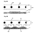
- Figs. 8A and 8B are schematic diagram demonstrating that the solid electrolyte fuel cell shown in Fig. 1 is excellent in durability.
- Figs. 9A to 9C are flow chart illustrating another example of the process for the production of the solid electrolyte fuel cell shown in Fig. 1.
- Fig. 10 is a graph illustrating the electricity-generating properties of the solid electrolyte fuel cell obtained by the production process shown in Fig. 9.
- Fig. 11 is a partial sectional view illustrating another method for forming the
second cathode layer 12. - Fig. 12 is an electron microphotograph of a section of the solid electrolyte fuel cell obtained in Example 1.
- Fig. 13 is a sectional view illustrating the related art solid electrolyte fuel cell.
- Fig. 14 is a graph illustrating the results of performance deterioration test on the solid electrolyte fuel cell shown in Fig. 13 by thermal shock.
- Fig. 15 is an electron microphotograph of a section of the solid electrolyte fuel cell shown in Fig. 13 after performance deterioration test by thermal shock.
- An example of the solid electrolyte fuel cell according to the invention is shown in Fig. 1. Fig. 1 is a partial sectional view of the solid electrolyte fuel cell. A
solid electrolyte layer 10 comprises acathode layer 16 provided on one side thereof havingplatinum metal wires anode layer 18 provided on the other side thereof havingplatinum metal wires - The
solid electrolyte layer 10 is a dense structure. As the solid electrolyte constituting thesolid electrolyte layer 10 there may be used any known solid electrolyte. Examples of the solid electrolyte employable herein include YSZ (yttria-stabilized zirconia), ScSZ (scandia-stabilized zirconia), zirconia-based ceramics obtained by doping these zirconia with Ce, A1, etc., and ceria-based ceramics such as SDC (samaria-doped ceria) and GDC (gadolia-doped ceria), and LSGM (lanthanum gallate) etc. - The
solid electrolyte layer 10 shown in Fig. 1 has two roughened portions having different periods to have a roughened surface. The two roughened portions are composed of a first roughened portion having a high period and a second roughened portion formed on the surface of the first roughened portion having a lower period than the first roughened portion. - The
cathode layer 16 formed on one side of thesolid electrolyte layer 10 has a two-layer structure composed of afirst cathode layer 12 provided in contact with one side of thesolid electrolyte layer 10 and asecond cathode layer 14 provided covering thefirst cathode layer 12 and havingplatinum metal wires second cathode layer 14 has a higher porosity than thefirst cathode layer 12. In some detail, while thefirst cathode layer 12 is a dense layer having a porosity of 10 vol-% or less, thesecond cathode layer 14 is a porous layer having a porosity of 50 vol-% or more (preferably 70 vol-% or less). - As the electrode material for cathode layer constituting the
cathode layer 16, too, there may be used any known electrode material for cathode layer. Examples of the electrode material for cathode layer employable herein include manganate/manganite compounds (e.g., lanthanum strontium manganite etc.), cobaltate/cobaltite compounds (e.g., samarium strontium cobaltite, lanthanum strontium cobaltite etc.) or ferrite compounds (e.g., lanthanum strontium ferrite etc.) of element belonging to the group III such as lanthanum having strontium (Sr) incorporated therein. - When the
first cathode layer 12 and thesecond cathode layer 14 constituting thecathode layer 16 each are formed by mixing an electrode material for cathode layer and an electrolyte constituting thesolid electrolyte layer 10, the difference in thermal expansion coefficient between thecathode layer 16 and thesolid electrolyte layer 10 can be reduced as much as possible, making it possible to prevent the exfoliation of thesolid electrolyte layer 10 and thecathode 16 from each other. - In particular, the predetermination of the mixing proportion of electrolyte in the
first cathode layer 12 disposed in close contact with thesolid electrolyte layer 10 among thefirst cathode layer 12 and thesecond cathode layer 14 to be more than that of thesecond cathode layer 14 makes it possible to form thecathode layer 16 as an electrolyte gradient layer and further enhance the heat resistance of the solid electrolyte fuel cell. - The
second cathode layer 14 can be formed by sheet-forming a porous layer paste obtained by mixing a predetermined amount of a cathode electrode material and an electrode with a pore-forming material, and then calcining the mixture at not lower than a temperature at which the pore-forming material can be gasified. As the pore-forming material there is preferably used a carbon-based pore-forming material. - The
first cathode layer 12 can be obtained by sheet-forming a dense layer paste obtained by mixing a predetermined amount of a cathode layer electrode material and an electrolyte free of pore-forming material, and then calcining the mixture at a predetermined temperature. - Further, in the solid electrolyte fuel cell shown in Fig. 1, the
first cathode layer 12 is divided into a plurality of island-shapedportions solid electrolyte layer 10 and thefirst cathode layer 12 can be dispersed. Thus, combined with the effect of the second roughened portion having a low period formed on one side of thesolid electrolyte layer 10, this arrangement makes it possible to prevent the exfoliation of thesolid electrolyte layer 10 and thefirst cathode layer 12 from each other. - The various island-shaped
portions first cathode layer 12 are each disposed on the recessed side of the first roughened portion having a high period formed on one side of thesolid electrolyte layer 10 and the gap between the island-shapedportion 12a and the island-shapedportion 12a is disposed on the raised side of the first roughened portion. Accordingly, the island-shapedportions portions portions portions 12a but is preferably from about 10 µm to 100 µm. -
Metal wires 20 made of platinum constituting a current collecting mesh metal are provided in thesecond cathode layer 14 in correspondence to the island-shapedportions - As the electrode material for anode layer constituting the
anode layer 18 on the other side of thesolid electrolyte layer 10 there may be used any known electrode material for anode layer. Examples of the electrode material for anode layer employable herein include cermets of nickel and cobalt with yttria-stabilized zirconia-based ceramics, scandia-stabilized zirconia-based ceramics or ceria-based (e.g., SDC, GDC, YDC) ceramics. As the electrode material for anode layer there may be also used a sintered material comprising as a main component (50 to 99% by weight) an electrically-conductive oxide. As the electrically-conductive oxide there may be used nickel oxide having lithium solidly dissolved therein or the like. This sintered material has an excellent oxidation resistance, making it possible to prevent the occurrence of phenomena due to oxidation of theanode layer 18 such as drop of electricity generating efficiency or incapability of generating electricity caused by the rise of resistivity of electrode of theanode layer 18 and exfoliation of theanode layer 18 from thesolid electrolyte layer 10. Further, an electrode material for anode layer obtained by incorporating a metal such as platinum group element or oxide thereof in the aforementioned electrode material for anode layer in an amount of from about 1 to 10% by weight, too, can form ananode layer 18 having high electricity-generating properties. - When the
aforementioned anode layer 18, too, is formed by mixing an electrode material for anode layer and an electrolyte, the difference in thermal expansion coefficient between theanode layer 18 and thesolid electrolyte layer 10 can be reduced as much as possible, making it possible to prevent the exfoliation of thesolid electrolyte layer 10 and theanode layer 18 from each other. - The
anode layer 18 can be formed by sheet-forming an anode layer paste obtained by mixing a predetermined amount of an electrode material for anode layer and an electrolyte, and then calcining the mixture at a predetermined temperature. - In order to produce the
solid electrolyte layer 10 shown in Fig. 1, asolid electrolyte layer 10 is formed at first. Thesolid electrolyte layer 10 can be obtained by pressing afabric green sheet 10a for solid electrolyte made of a solid electrolyte as shown in Fig. 2, peeling thefabric green sheet 10a, and then calcining thegreen sheet 10a at a predetermined temperature. Thesolid electrolyte layer 10 shown in Fig. 3A obtained by calcining has two roughened portions having different periods formed on the both sides thereof to have a roughened surface. Among the two roughened portions, the first roughenedportion 11a having a higher period is formed by the portion between the crossings ofwarp 22a andweft 22b constituting thefabric 22. The second roughenedportion 11b having a lower period formed on the surface of the first roughenedportion 11a is formed by a singlefiber constituting warp 22a orweft 22b. - Subsequently, the aforementioned porous layer paste is printed over the
first cathode sheet 32 formed by printing the dense layer paste as shown in Fig. 3B to form asecond cathode sheet 34 on one side of thesolid electrolyte layer 10 shown in Fig. 3A. - Further, the aforementioned anode layer paste is printed over the other side of the
solid electrolyte layer 10 to form ananode sheet 38. - The
second cathode sheet 34 and theanode sheet 38 each have a mesh metal made ofmetal wire - The mesh metal is embedded in the
second cathode sheet 34 in such an arrangement that themetal wire portion 11a having a highr period of thesolid electrolyte layer 10. The mesh metal may be fixed to the surface of thesecond cathode sheet 34. - Thereafter, the laminate shown in Fig. 3B is calcined at a temperature at which the pore-forming material incorporated in the
second cathode sheet 34 can be gasified to obtain the solid electrolyte fuel cell shown in Fig. 1. - In some detail, in the
first cathode sheet 32, the portion corresponding to the raised portion of the first roughenedportion 11a having a higher period formed on the surface of thesolid electrolyte layer 10 is thinner than the portion corresponding to the recessed portion of the first roughenedportion 11a. In this arrangement, the thin portion of thefirst cathode sheet 32 breaks into a plurality of island-shapedportions first cathode sheet 32 is calcined while being divided into portions corresponding to the raised portions of the first roughenedportion 11a having a higher period formed on the surface of thesolid electrolyte layer 10. Thus, the island-shapedportions portion 12a and the island-shapedportion 12a can be substantially the same. - Further, the pore-forming material incorporated in the
second cathode sheet 34 is gasified to form asecond cathode layer 14 which is more porous than thefirst cathode layer 12. As a result, the solid electrolyte fuel cell shown in Fig. 1 can be obtained. - As previously mentioned, the solid electrolyte fuel cell shown in Fig. 1 is disposed in or in the vicinity of flame on the
anode layer 18 side thereof in the open atmosphere. The disposition of theanode layer 18 opposed to flame makes it easy to use also hydrocarbon, hydrogen, radicals (OH, CH, C2, O2H, CH3) present in the flame as fuel. - Further, the surface of the solid electrolyte fuel cell on the
cathode layer 16 side thereof can be exposed to the atmosphere, making it easy to use oxygen in the atmosphere. Moreover, a gas containing oxygen (air, oxygen-rich gas, etc.) may be blown against thecathode layer 16 so that thecathode layer 16 can use oxygen efficiently. - Although the solid electrolyte fuel cell is disposed in or in the vicinity of flame as mentioned above, the solid electrolyte fuel cell is preferably disposed in reducing flame, which is the root of flame. The disposition of the solid electrolyte fuel cell in reducing flame makes it possible to use hydrocarbon, hydrogen, radicals, etc. present in reducing flame as fuel. Even when an
anode layer 18 made of an electrode material for anode layer which can be easily oxidized and deteriorated is used, the resulting solid electrolyte fuel cell can maintain its durability. - As the fuel there may be used any material which can be combusted and oxidized to generate flame (combustible material).
- The relationship between the amount of pore-forming material incorporated in the porous layer paste constituting the
second cathode sheet 34 shown in Fig. 3 and the electric power of the solid electrolyte fuel cell thus obtained is graphically shown in Fig. 4. - In the graph of Fig. 4, the abscissa indicates the amount of carbon-based pore-forming material incorporated in the porous layer paste and the ordinate indicates the maximum output of the solid electrolyte fuel cell thus obtained. The graph of Fig. 4 depicts the maximum output of solid electrolyte fuel cells obtained from different anode layer electrode materials constituting the
anode layer 18. - As can be seen in the graph of Fig. 4, when the amount of pore-forming material incorporated in the porous layer paste is from 50 to 70 vol-%, the maximum output of the solid electrolyte fuel cell thus obtained can be enhanced.
- While the foregoing description is made with reference to the case where the
second cathode layer 14 and theanode layer 18 each have a mesh metal provided therein, a linear metal may be provided in these layers. - A premixed flame of butane gas as a fuel from a burner is applied to the surface of the solid electrolyte fuel cell shown in Fig. 1 on the
anode layer 18 side thereof to examine the electricity-generating properties thereof. Thereafter, the solid electrolyte fuel cell is sufficiently separated from the flame so that the temperature of the entire solid electrolyte fuel cell is returned to room temperature. Thereafter, the premixed flame from a burner is again applied to the solid electrolyte fuel cell on theanode layer 18 side thereof. This procedure is then repeated to subject the solid electrolyte fuel cell to test on performance deterioration by thermal shock. The results are shown in Fig. 5. As can be seen in the electricity-generating properties shown in Fig. 5, the solid electrolyte fuel cell shown in Fig. 1 showed a remarkably reduced drop of electricity-generating properties as compared with the related art solid electrolyte fuel cell shown in Fig. 14 even after 10 repetitions of thermal shock. - In Fig. 5, the circular marks depict electric power (solid mark) and voltage (blank mark) developed after no thermal shock, the triangular marks depict electric power (solid mark) and voltage (blank mark) developed after five repetitions of thermal shock and the rectangular marks depict electric power (solid mark) and voltage (blank mark) developed after ten repetitions of thermal shock.
- On the other hand, the solid electrolyte fuel cell shown in Fig. 6 is formed by the same composition as the forming materials constituting the constituents of the solid electrolyte fuel cell shown in Fig. 1 . In the solid electrolyte fuel cell of Fig. 6, a
solid electrolyte layer 200 both sides of which are flat has acathode layer 206 laminated on one side thereof and ananode layer 210 laminated on the other side thereof. Thecathode layer 206 is a two-layer structure composed of afirst cathode layer 202 provided in contact with one side of thesolid electrolyte layer 200 and asecond cathode layer 204 provided covering thefirst cathode layer 202. Thesecond cathode layer 204 has a higher porosity than thefirst cathode layer 202. Thefirst cathode layer 202 has no divisions and is in the form of sheet. - The
second cathode layer 204 and theanode layer 210 each have aplatinum metal wire - The solid electrolyte fuel cell shown in Fig. 6 is subjected to the same test on performance deterioration by thermal shock as effected above. As a result, electricity-generating properties shown in Fig. 7 are exhibited. As can be seen in the electricity-generating properties shown in Fig. 7, the solid electrolyte fuel cell of Fig. 6 showed a greater deterioration of electricity-generating properties developed after 10 repetitions of thermal shock than the solid electrolyte fuel cell of Fig. 1, the electricity-generating properties of which is shown in Fig. 5.
- In Fig. 7, the circular marks depict electric power (solid mark) and voltage (blank mark) developed after no thermal shock, the triangular marks depict electric power (solid mark) and voltage (blank mark) developed after five repetitions of thermal shock and the rectangular marks depict electric power (solid mark) and voltage (blank mark) developed after ten repetitions of thermal shock.
- The reason why the solid electrolyte fuel cell shown in Fig. 6 shows a greater drop of electricity-generating properties after 10 repetitions of thermal shock than the solid electrolyte fuel cell shown in Fig. 1 is presumably as follows.
- In other words, as shown in Fig. 8A, the
first cathode layer 202 provided in contact with one side of thesolid electrolyte layer 200 has no divisions. Therefore, when the solid electrolyte fuel cell in the form of sheet undergoes thermal shock, the interface of thesolid electrolyte layer 200 with thefirst cathode layer 202 is given a great stress caused by the difference in thermal expansion coefficient between the two layers. As a result, the site where thesolid electrolyte layer 200 and thefirst cathode layer 202 are bonded with a low adhesion undergoes partial exfoliation. - On the other hand, as shown in Fig. 8B, in the case where the
first cathode layer 12 provided in contact with one side of thesolid electrolyte layer 10 has a plurality of island-shapeddivisions solid electrolyte layer 10 with the island-shapedportions first cathode layer 12 undergoes dispersion of stress caused by the difference in thermal expansion coefficient between the two layers. As a result, the exfoliation of thesolid electrolyte layer 10 and the island-shapedportions first cathode layer 12 from each other can be prevented. - As can be seen in the electricity-generating properties shown in Fig. 5, the solid electrolyte fuel cell shown in Fig. 1 is found to have some drop of electricity-generating properties after 10 repetitions of thermal shock. The inventors presumes that the some drop of electricity-generating properties is attributed to the simultaneous calcining of the
first cathode sheet 32 and thesecond cathode sheet 34. The inventors then make a study of sequential calcining of thefirst cathode sheet 32 and thesecond cathode sheet 34. - Firstly, as shown in Fig. 9A, the inventors print the dense layer paste previously mentioned over one side of the
solid electrolyte layer 10 to form afirst cathode sheet 32. Thefirst cathode sheet 32 is then tentatively calcined to form a tentatively calcined material 32'. During the tentative calcining, the thin portion of thefirst cathode sheet 32 breaks into a plurality of island-shaped portions 32'a, 32'a · · due to stress caused by the resulting thermal expansion or thermal shrinkage as shown in Fig. 9B. - Subsequently, as shown in Fig. 9C, the porous layer paste previously mentioned is printed over the tentatively calcined material 32' to form a
second cathode sheet 34. At the same time, the anode layer paste previously mentioned is printed over the other side of thesolid electrolyte layer 10 to form ananode sheet 38. - The
second cathode sheet 34 and theanode sheet 38 each have a mesh metal made ofmetal wire - The mesh metal is embedded in the
second cathode sheet 34 in such an arrangement that themetal wire second cathode sheet 34. - Thereafter, the laminate shown in Fig. 9C is calcined to cause the gap between the island-shaped
portions 12a constituting the first cathode layer to be filled with the material constituting thesecond cathode layer 14. - Owing to this, it is possible to effectively use the spaces between the island-shaped
portions 12a. - A premixed flame of butane gas as a fuel from a burner is applied to the surface of the solid electrolyte fuel cell thus obtained on the anode layer side thereof to examine the electricity-generating properties thereof. The results are shown in Fig. 10. As can be seen in the electricity-generating properties shown in Fig. 10, the solid electrolyte fuel cell obtained by subjecting the
first cathode sheet 32 formed on one side of thesolid electrolyte layer 10 to tentative calcining exhibits enhanced electricity-generating properties as compared with the solid electrolyte fuel cell obtained without subjecting thefirst cathode sheet 32 to tentative calcining. - In Fig. 10, the circular marks each indicate the product obtained without tentative calcining (solid mark: electric power) and the rectangular marks each indicate the product obtained by tentative calcining (blank mark: voltage (potential)).
- While the solid electrolyte fuel cells of Figs. 1 to 10 described above each are obtained in such a manner that the first roughened surface formed on one side of the solid electrolyte layer10 is made the use of to form the
first cathode layer 12 having a plurality of island-shapeddivisions first cathode sheet 32 which has been previously divided into island-shapedportions solid electrolyte layer 10 as shown in Fig. 11. Thefirst cathode sheet 32 which has been previously divided into island-shapedportions solid electrolyte layer 10. - While the solid electrolyte fuel cells shown in Figs. 1 to 10 each comprise a
solid electrolyte layer 10 the both sides of which have two roughened portions having different periods to have a roughened surface as a solid electrolyte layer, a solid electrolyte layer one side of which have only a first roughened portion having a high period to have a roughened surface may be used. This solid electrolyte layer can be formed by pressing a mask sheet having raised portions at a predetermined interval against one side of the solid electrolytegreen sheet 10a. - In order to prepare a
solid electrolyte layer 10, aplain weave fabric fabric fabric - The solid electrolyte green sheet is stamped into a circular form which is then calcined at 1,300°C to obtain a ceramic substrate made of Sm0.2Ce0.8O1.9 (samaria-doped ceria: SDC) having a thickness of 180 µm and a diameter φ of 15 mm.
- A dense layer paste made of Sm0.5Sr0.5CoO3 (samarium strontium cobaltite: SSC) having SDC incorporated therein in an amount of 50 wt-% is then sheet-printed (printed area: 1.3 cm2) as a
first cathode sheet 32 constituting thefirst cathode layer 12 over one side (area: 1.8 cm2) of the ceramic substrate thus obtained assolid electrolyte layer 10. - Further, an anode layer paste obtained by mixing 20 wt-% of SDC, 5 wt-% of Rh2O3 (rhodium oxide) and 8 mol-% of Li-NiO2 is sheet-printed as an
anode sheet 38 constituting theanode layer 18 on the other side of the ceramic substrate (printed area: 1.3 cm2). - Moreover, a porous layer paste made of SSC having 55 vol-% of a carbon-based pore-forming material and 30 wt-% of SDC incorporated therein is sheet-printed as a
second cathode sheet 34 constituting thesecond cathode layer 14 over the first cathode sheet 32 (printed area: 1.3 cm2). - Subsequently, a mesh metal gauge (#80; distance between metal wires: 320 µm) formed by welding platinum wire is embedded in the
second cathode sheet 34 and theanode sheet 38. The laminate is then calcined at 1,200°C in the atmosphere for 1 hour to obtain a solid electrolyte fuel cell. - An electron microphotograph of a section of the solid electrolyte fuel cell thus obtained is shown in Fig. 12. As can be seen in the electron microphotograph shown in Fig. 12, a first cathode layer having a plurality of island-shaped divisions is formed on one side of the solid electrolyte layer having a first roughened portion having a period of 300 µm formed on the both sides thereof. The first cathode layer is covered by the second cathode layer. (The first cathode layer has a second roughened portion having a lower period than the first roughened portion formed on the surface thereof, but this is not definitely shown in the electron microphotograph shown in Fig. 12.)
- The island-shaped portions of the first cathode layer are each disposed on the recessed portion of the roughened portions of the solid electrolyte layer. The gap between the island-shaped portions is disposed in the raised portion of the first roughened portions of the solid electrolyte layer.
- Further, the metal wire of mesh metal gauge is disposed above the island-shaped portions of the first cathode layer wrapped by the forming material constituting the second cathode layer.
- The length of the island-shaped portions of the first cathode layer is from 100 µm to 300 µm and the gap between the island-shaped portions is from 10 µm to 100 µm.
- A premixed flame of butane gas as a fuel from a 6. 5% burner is applied to the surface of the solid electrolyte fuel cell thus obtained on the anode layer side thereof to examine the electricity-generating properties thereof. Thereafter, the solid electrolyte fuel cell is sufficiently separated from the flame so that the temperature of the entire solid electrolyte fuel cell is returned to room temperature. Thereafter, the premixed flame from a burner is again applied to the solid electrolyte fuel cell on the
anode layer 18 side thereof. This procedure is then repeated ten times to subject the solid electrolyte fuel cell to test on performance deterioration by thermal shock. The results are shown in Fig. 5. - As can be seen in the electricity-generating properties shown in Fig. 5, the solid electrolyte fuel cell showed little or no deterioration of electricity- generating properties even after 10 repetitions of thermal shock.
- The procedure of Example 1 is followed except that the solid electrolyte green sheet is calcined without pressing
fabric cathode layer 16 is formed only by the first cathode layer 12 (dense layer). Thus, a solid electrolyte fuel cell shown in Fig. 13 is prepared. - The solid electrolyte fuel cell of Fig. 13 thus obtained is then subjected to the same thermal shock test as effected in Example 1. The results are shown in Fig. 14.
- As can be seen in the electricity-generating properties shown in Fig. 14, the solid electrolyte fuel cell showed some deterioration of electricity-generating properties every thermal shock. In Fig. 14, this phenomenon is shown by the arrow A indicating the direction of drop of electric power.
- The procedure of Example 1 is followed except that the solid electrolyte green sheet is calcined without pressing
fabric - The solid electrolyte fuel cell of Fig. 6 thus obtained is then subjected to the same thermal shock test as effected in Example 1. The results are shown in Fig. 7.
- As can be seen in the electricity-generating properties shown in Fig. 7, the solid electrolyte fuel cell shown in Fig. 6 showed a definite deterioration of electricity-generating properties after 10 repetitions of thermal shock.
- In order to prepare a
solid electrolyte layer 10, aplain weave fabric fabric fabric - The solid electrolyte green sheet is stamped into a circular form which is then calcined at 1,300°C to obtain a ceramic substrate made of Sm0.2Ce0.8O1.9 (samaria-doped ceria: SDC) having a thickness of 180 µm and a diameter φ of 15 mm.
- A dense layer paste made of Sm0.5Sr0.5CoO3 (samarium strontium cobaltite: SSC) having SDC incorporated therein in an amount of 50 wt-% is then sheet-printed (printed area: 1.3 cm2) as a
first cathode sheet 32 constituting thefirst cathode layer 12 constituting thecathode layer 16 over one side (area: 1.8 cm2) of the ceramic substrate thus obtained assolid electrolyte layer 10. - The
first cathode sheet 32 thus obtained is subjected to tentative calcining at a temperature of 1,200°C for 1 hour to form a tentatively calcined material 32' . An anode layer paste obtained by mixing 20 wt-% of SDC, 5 wt-% of Rh2O3 (rhodium oxide) and 8 mol-% of Li-NiO2 is sheet-printed as ananode sheet 38 constituting theanode layer 18 on the other side of the ceramic substrate (printed area: 1.3 cm2). - Moreover, a porous layer paste made of SSC having 55 vol-% of a carbon-based pore-forming material and 30 wt-% of SDC incorporated therein is sheet-printed as a
second cathode sheet 34 constituting thesecond sheet 14 constituting thecathode layer 16 over the tentatively calcined material 32' (printed area: 1.3 cm2). - Subsequently, a mesh metal gauge (#80; distance between metal wires: 320 µm) formed by welding platinum wire is embedded in the
second cathode sheet 34 and theanode sheet 38. The laminate is then calcined at 1,200°C in the atmosphere for 1 hour to obtain a solid electrolyte fuel cell. - The solid electrolyte fuel cell obtained in the present example shows substantially the same section as that of the solid electrolyte fuel cell obtained in Example 1 shown in Fig. 12.
- As can be seen in the section shown in Fig. 12, however, the solid electrolyte fuel cell obtained in the present example is observed to have little or no space between the island-shaped portions constituting the first cathode layer.
- A premixed flame of butane gas as a fuel from a 6.5% burner is applied to the surface of the solid electrolyte fuel cell thus obtained on the anode layer side thereof to examine the electricity-generating properties thereof. The results are shown in Fig. 10. Fig. 10 also depicts the electricity-generating properties of the solid electrolyte fuel cell obtained in Example 1 as an example of the results of the "product obtained without tentative calcining".
- As can be seen in the electricity-generating properties shown in Fig. 10, the solid electrolyte fuel cell exhibits better electricity-generating properties than the solid electrolyte fuel cell obtained in Example 1.
Claims (21)
- A solid electrolyte fuel cell comprising:a solid electrolyte layer (10),a cathode layer (16) formed on one side of the solid electrolyte layer, andan anode layer (18) formed on the other side of the solid electrolyte layer, whereinthe cathode layer includes a first cathode layer (12) formed in contact with the solid electrolyte layer and a second cathode layer (14) formed covering the first cathode layer,the second cathode layer has a higher porosity than the first cathode layer, andthe first cathode layer is divided into a plurality of island-shaped portions (12a).
- The solid electrolyte fuel cell as defined in Claim 1, wherein
the plurality of island-shaped portions (12a) constituting the first cathode layer (12) are periodically formed. - The solid electrolyte fuel cell as defined in any of Claims 1 to 2, wherein
the gap between the plurality of island-shaped portions of the first cathode layer is filled with a molding material constituting the second cathode layer. - The solid electrolyte fuel cell as defined in any of Claims 1 to 3, wherein
the surface of the solid electrolyte layer (10) on the cathode layer side thereof is periodically roughened to have a roughened surface,
the roughened portion has the island-shaped portions constituting the first cathode layer disposed on the recessed side thereof and the gap between the island-shaped portions disposed on the raised side thereof. - The solid electrolyte fuel cell as defined in Claim 1, wherein
the surface of the solid electrolyte layer has two roughened portions having different periods to have a roughened surface,
the two roughened portions are composed of:a first roughened portion (11a) in which a recessed portion corresponding to the island-shaped portions constituting the first cathode layer disposed thereon and the raised portion having the gap between the island-shaped portions provided thereon occur in turn periodically, anda second roughened portion (11b) having a lower period than the first roughened portion formed on the first roughened portion. - The solid electrolyte fuel cell as defined in any of Claims 1 to 5, wherein
a metal wire (20) constituting a current collecting mesh metal or linear metal embedded in or fixed to the second cathode layer (14) is provided for each of the island-shaped portions constituting the first cathode layer. - The solid electrolyte fuel cell as defined in any of Claims 1 to 6, wherein
the porosity of the first cathode layer (12) is 10 vol-% or less, and
the porosity of the second cathode layer (14) is 50 vol-% or more. - The solid electrolyte fuel cell as defined in any of Claims 1 to 7, wherein
the second cathode layer (14) is a porous layer obtained by adding a pore-forming material gasified at the calcining temperature of the cathode layer during the calcining thereof, and
the first cathode layer (12) is a dense layer obtained by calcining without adding the pore-forming material. - The solid electrolyte fuel cell as defined in Claim 8, wherein
the added amount of the pore-forming material is from 50 to 70 vol-%. - The solid electrolyte fuel cell as defined in any of Claims 1 to 9, wherein
the first cathode layer (12) and the second cathode layer (14) each comprise an electrolyte constituting the solid electrolyte layer (10) and an electrode material incorporated therein in admixture. - The solid electrolyte fuel cell as defined in Claim 10, wherein
the first cathode layer has a higher mixing proportion of solid electrolyte than the second cathode layer. - The solid electrolyte fuel cell as defined in any of Claims 1 to 11, wherein
when the solid electrolyte fuel cell is exposed to flame on one side thereof in the open atmosphere to generate electricity, the solid electrolyte fuel cell is exposed to flame on the anode layer side thereof and open to the atmosphere on the cathode layer side thereof. - A method for producing a solid electrolyte fuel cell, comprising the steps of:laminating a first cathode sheet (32) having an electrode material for cathode layer incorporated therein on one side of a solid electrolyte layer (10),laminating a second cathode sheet (34) having the electrode material for cathode layer and a pore-forming material incorporated therein on the first cathode sheet,laminating an anode sheet having an electrode material for anode layer incorporated therein on the other side of the solid electrolyte layer, andcalcining the first cathode sheet, the second cathode sheet and anode sheet at a temperature at which the pore-forming material is gasified to form a first cathode layer (12), a second cathode layer (14) and an anode layer (18), whereinbefore or during the calcining, the first cathode sheet is divided into a plurality of island-shaped portions to form a first cathode layer including a plurality of island-shaped divisions on one side of the solid electrolyte layer.
- The method for producing a solid electrolyte fuel cell as defined in Claim 13, wherein
the surface of one side of the solid electrolyte layer having a first cathode sheet laminated thereon has a roughened portion formed thereon having a recessed portion corresponding to the island-shaped portions constituting the first cathode layer obtained by calcining the first cathode sheet and a raised portion corresponding to the gap between the island-shaped portions, the recessed portion and the raised portion occurring in turn periodically, so that the surface of one side of the solid electrolyte layer is roughened. - The method for producing a solid electrolyte fuel cell as defined in Claim 13, wherein
the solid electrolyte layer (10) has two kinds of roughened portions having different periods to have a roughened surface on the surface on which the first cathode sheet is laminated, wherein
the two kinds of roughened portions are composed of:a first roughed portion (11a) in which a recessed portion corresponding to island-shaped portions constituting the first cathode layer obtained by calcining the first cathode sheet, and a raised portion corresponding to the gap between the island-shaped portions occur in turn periodically, anda second roughened portion (11b) formed on the surface of the first roughed portion and having a lower period than the first roughened portion. - The method for producing a solid electrolyte fuel cell as defined in Claim 15, further comprising the steps of:pressing a fabric made of an organic fiber or metallic fiber against at least one side of a green sheet for solid electrolyte constituting the solid electrolyte layer, so that a first roughened portion having a period in which a recessed portion and a raised portion occur in turn periodically is formed on the one surface of the green sheet by the crossing of weft and warp constituting the fabric and a second roughened portion having a lower period than the first roughened portion is formed on the surface of the first roughened portion by the single fiber constituting the weft and warp, andcalcining the green sheet for solid electrolyte.
- The method for producing a solid electrolyte fuel cell as defined in any of Claims 13 to 16, further comprising the steps of:laminating a first cathode sheet on one side of a solid electrolyte layer having a recessed portion corresponding to island-shaped portions constituting a first cathode layer obtained by calcining the first cathode sheet and a raised portion corresponding to the gap between the island-shaped portions occur in turn periodically,subjecting the first cathode sheet to tentative calcining so that the plurality of island-shaped portions constituting the first cathode layer are each formed in the recessed portion constituting the roughened portion of the solid electrolyte layer,laminating a second cathode sheet on the top of the first cathode layer and an anode sheet on the other side of the solid electrolyte layer, andsubjecting the first cathode layer and the second cathode sheet and the anode sheet to calcining.
- The method for producing a solid electrolyte fuel cell as defined in any of Claims 13 to 17, wherein
a current collecting mesh metal or linear metal is embedded in or fixed to the second cathode sheet or anode sheet, and
as the mesh metal or linear metal, a mesh metal or linear metal has a metal wire provided therein in correspondence to the island-shaped portions constituting the first cathode layer obtained by calcining the first cathode sheet. - The method for producing a solid electrolyte fuel cell as defined in any of Claims 13 to 18, wherein
the amount of the pore-forming material to be incorporated in the second cathode sheet is from 50 to 70 vol-%. - The method for producing a solid electrolyte fuel cell as defined in any of Claims 13 to 19, wherein
the first cathode sheet and the second cathode sheet have an electrolyte constituting the solid electrolyte layer and an electrode material incorporated therein in admixture, respectively. - The method for producing a solid electrolyte fuel cell as defined in Claim 20, wherein
the first cathode sheet comprises a solid electrolyte incorporated therein in a greater amount than the second cathode sheet.
Applications Claiming Priority (1)
| Application Number | Priority Date | Filing Date | Title |
|---|---|---|---|
| JP2006094432A JP4861735B2 (en) | 2006-03-30 | 2006-03-30 | Solid electrolyte fuel cell and manufacturing method thereof |
Publications (3)
| Publication Number | Publication Date |
|---|---|
| EP1840999A2 true EP1840999A2 (en) | 2007-10-03 |
| EP1840999A3 EP1840999A3 (en) | 2009-01-21 |
| EP1840999B1 EP1840999B1 (en) | 2010-02-17 |
Family
ID=38229213
Family Applications (1)
| Application Number | Title | Priority Date | Filing Date |
|---|---|---|---|
| EP07006699A Expired - Fee Related EP1840999B1 (en) | 2006-03-30 | 2007-03-30 | Solid electrolyte fuel cell and process for the production thereof |
Country Status (6)
| Country | Link |
|---|---|
| US (1) | US8304129B2 (en) |
| EP (1) | EP1840999B1 (en) |
| JP (1) | JP4861735B2 (en) |
| CN (1) | CN101047259B (en) |
| CA (1) | CA2582955A1 (en) |
| DE (1) | DE602007004758D1 (en) |
Cited By (1)
| Publication number | Priority date | Publication date | Assignee | Title |
|---|---|---|---|---|
| EP1858106A2 (en) | 2006-04-24 | 2007-11-21 | Ngk Insulators, Ltd. | Ceramic thin plate member |
Families Citing this family (16)
| Publication number | Priority date | Publication date | Assignee | Title |
|---|---|---|---|---|
| JP5126812B2 (en) * | 2007-04-17 | 2013-01-23 | パナソニック株式会社 | Direct oxidation fuel cell |
| US20090148743A1 (en) * | 2007-12-07 | 2009-06-11 | Day Michael J | High performance multilayer electrodes for use in oxygen-containing gases |
| US8828618B2 (en) * | 2007-12-07 | 2014-09-09 | Nextech Materials, Ltd. | High performance multilayer electrodes for use in reducing gases |
| JP5292898B2 (en) * | 2008-03-31 | 2013-09-18 | 大日本印刷株式会社 | Solid oxide fuel cell and method for producing the same |
| WO2010077683A1 (en) * | 2008-12-08 | 2010-07-08 | Nextech Materials, Ltd. | Current collectors for solid oxide fuel cell stacks |
| JP5375208B2 (en) * | 2009-03-05 | 2013-12-25 | トヨタ自動車株式会社 | Fuel cell manufacturing method, fuel cell |
| JP5499675B2 (en) * | 2009-12-11 | 2014-05-21 | Tdk株式会社 | Power generation cell for solid oxide fuel cell and solid oxide fuel cell |
| KR101179137B1 (en) | 2010-07-01 | 2012-09-07 | 한국전력공사 | Single cell of solid oxide fuel cell and method for manufacturing thereof |
| JP5447578B2 (en) * | 2012-04-27 | 2014-03-19 | 株式会社豊田自動織機 | Solid electrolyte and secondary battery |
| WO2014050148A1 (en) * | 2012-09-28 | 2014-04-03 | 株式会社日本触媒 | Half cell for solid oxide fuel cells, and solid oxide fuel cell |
| US10651476B2 (en) * | 2015-07-29 | 2020-05-12 | Kyocera Corporation | Cell stack device, module, and module housing device |
| US20200350595A1 (en) * | 2017-10-16 | 2020-11-05 | Northwestern University | Solid oxide electrolyte materials for electrochemical cells |
| CN109560249A (en) * | 2018-11-30 | 2019-04-02 | 中国科学院过程工程研究所 | A kind of double-layer structure anode pole piece, and its preparation method and application |
| WO2021020423A1 (en) * | 2019-07-29 | 2021-02-04 | 株式会社村田製作所 | Electrolyte sheet for solid oxide fuel cell, method for manufacturing electrolyte sheet for solid oxide fuel cell, and unit cell for solid oxide fuel cell |
| JP7452480B2 (en) | 2021-03-25 | 2024-03-19 | トヨタ自動車株式会社 | Catalyst layer and its manufacturing method |
| CN113937355B (en) * | 2021-08-31 | 2023-08-22 | 河北光兴半导体技术有限公司 | Solid electrolyte sheet, and preparation method and application thereof |
Citations (7)
| Publication number | Priority date | Publication date | Assignee | Title |
|---|---|---|---|---|
| JPH03134963A (en) | 1989-10-19 | 1991-06-07 | Fuji Electric Co Ltd | Solid electrolyte type fuel cell |
| EP0615299A1 (en) | 1993-03-10 | 1994-09-14 | Murata Manufacturing Co., Ltd. | Solid oxide fuel cell and manufacturing method thereof |
| US6316138B1 (en) | 1994-07-11 | 2001-11-13 | Mitsubishi, Jukogyo Kabushiki Kaisha | Solid oxide electrolyte fuel cell |
| GB2400723A (en) | 2003-04-15 | 2004-10-20 | Ceres Power Ltd | Solid oxide fuel cell for a novel substrate and a method for fabricating the same |
| US20050092597A1 (en) | 2003-10-29 | 2005-05-05 | O'neil James | Method of forming thin-film electrodes |
| JP2005235549A (en) | 2004-02-19 | 2005-09-02 | Mitsubishi Materials Corp | Solid oxide fuel cell |
| US20050249993A1 (en) | 2004-05-10 | 2005-11-10 | Michio Horiuchi | Solid electrolyte fuel cell configuration |
Family Cites Families (15)
| Publication number | Priority date | Publication date | Assignee | Title |
|---|---|---|---|---|
| US4135040A (en) * | 1977-12-20 | 1979-01-16 | General Electric Company | Solid ion-conductive electrolyte body and method of forming |
| JPH0364861A (en) * | 1989-08-02 | 1991-03-20 | Mitsubishi Heavy Ind Ltd | Solid electrolyte fuel cell |
| JPH0748378B2 (en) * | 1991-03-28 | 1995-05-24 | 日本碍子株式会社 | Air electrode for solid electrolyte fuel cell and solid electrolyte fuel cell having the same |
| US5364711A (en) * | 1992-04-01 | 1994-11-15 | Kabushiki Kaisha Toshiba | Fuel cell |
| DK171621B1 (en) * | 1993-03-01 | 1997-02-24 | Risoe Forskningscenter | Solid oxide fuel cell with cathode of LSM and YSZ |
| JP3347561B2 (en) * | 1995-12-21 | 2002-11-20 | 京セラ株式会社 | Solid oxide fuel cell |
| JP3230156B2 (en) * | 1999-01-06 | 2001-11-19 | 三菱マテリアル株式会社 | Electrode of solid oxide fuel cell and method of manufacturing the same |
| US7067208B2 (en) * | 2002-02-20 | 2006-06-27 | Ion America Corporation | Load matched power generation system including a solid oxide fuel cell and a heat pump and an optional turbine |
| JP4104418B2 (en) * | 2002-10-21 | 2008-06-18 | 新光電気工業株式会社 | Fuel cell |
| US7118826B2 (en) * | 2003-04-24 | 2006-10-10 | Hewlett-Packard Development Company, L.P. | Electrode-electrolyte composites having discrete regions |
| US7531261B2 (en) * | 2003-06-30 | 2009-05-12 | Corning Incorporated | Textured electrolyte sheet for solid oxide fuel cell |
| JP2005063686A (en) | 2003-08-11 | 2005-03-10 | Shinko Electric Ind Co Ltd | Solid electrolyte fuel cell |
| WO2007001343A2 (en) * | 2004-08-20 | 2007-01-04 | Ion America Corporation | Nanostructured fuel cell electrode |
| CN101171371A (en) * | 2005-04-29 | 2008-04-30 | 纳幕尔杜邦公司 | Membrane-mediated electropolishing with topographically patterned membranes |
| JP2006324190A (en) * | 2005-05-20 | 2006-11-30 | Shinko Electric Ind Co Ltd | Solid oxide fuel cell and its manufacturing method |
-
2006
- 2006-03-30 JP JP2006094432A patent/JP4861735B2/en not_active Expired - Fee Related
-
2007
- 2007-03-27 US US11/727,520 patent/US8304129B2/en active Active
- 2007-03-28 CA CA002582955A patent/CA2582955A1/en not_active Abandoned
- 2007-03-30 DE DE602007004758T patent/DE602007004758D1/en active Active
- 2007-03-30 CN CN2007100875639A patent/CN101047259B/en not_active Expired - Fee Related
- 2007-03-30 EP EP07006699A patent/EP1840999B1/en not_active Expired - Fee Related
Patent Citations (7)
| Publication number | Priority date | Publication date | Assignee | Title |
|---|---|---|---|---|
| JPH03134963A (en) | 1989-10-19 | 1991-06-07 | Fuji Electric Co Ltd | Solid electrolyte type fuel cell |
| EP0615299A1 (en) | 1993-03-10 | 1994-09-14 | Murata Manufacturing Co., Ltd. | Solid oxide fuel cell and manufacturing method thereof |
| US6316138B1 (en) | 1994-07-11 | 2001-11-13 | Mitsubishi, Jukogyo Kabushiki Kaisha | Solid oxide electrolyte fuel cell |
| GB2400723A (en) | 2003-04-15 | 2004-10-20 | Ceres Power Ltd | Solid oxide fuel cell for a novel substrate and a method for fabricating the same |
| US20050092597A1 (en) | 2003-10-29 | 2005-05-05 | O'neil James | Method of forming thin-film electrodes |
| JP2005235549A (en) | 2004-02-19 | 2005-09-02 | Mitsubishi Materials Corp | Solid oxide fuel cell |
| US20050249993A1 (en) | 2004-05-10 | 2005-11-10 | Michio Horiuchi | Solid electrolyte fuel cell configuration |
Cited By (3)
| Publication number | Priority date | Publication date | Assignee | Title |
|---|---|---|---|---|
| EP1858106A2 (en) | 2006-04-24 | 2007-11-21 | Ngk Insulators, Ltd. | Ceramic thin plate member |
| EP1858106A3 (en) * | 2006-04-24 | 2009-05-06 | Ngk Insulators, Ltd. | Ceramic thin plate member |
| US7927755B2 (en) | 2006-04-24 | 2011-04-19 | Ngk Insulators, Ltd. | Ceramic thin plate member |
Also Published As
| Publication number | Publication date |
|---|---|
| CN101047259B (en) | 2010-07-21 |
| CA2582955A1 (en) | 2007-09-30 |
| US8304129B2 (en) | 2012-11-06 |
| EP1840999B1 (en) | 2010-02-17 |
| JP4861735B2 (en) | 2012-01-25 |
| US20070238007A1 (en) | 2007-10-11 |
| CN101047259A (en) | 2007-10-03 |
| EP1840999A3 (en) | 2009-01-21 |
| JP2007273144A (en) | 2007-10-18 |
| DE602007004758D1 (en) | 2010-04-01 |
Similar Documents
| Publication | Publication Date | Title |
|---|---|---|
| EP1840999B1 (en) | Solid electrolyte fuel cell and process for the production thereof | |
| EP1791211B1 (en) | Solid electrolyte fuel cell comprising a fired anode and a multi-layered porous cathode | |
| EP2398103B1 (en) | Fuel cell | |
| EP2398102B1 (en) | Fuel cell | |
| US8021799B2 (en) | High-performance ceramic anodes for use with strategic and other hydrocarbon fuels | |
| JP6658754B2 (en) | Solid oxide fuel cell and method for producing electrolyte layer-anode assembly | |
| JP2006518919A (en) | Porous electrode, solid oxide fuel cell, and manufacturing method thereof | |
| CA2956069A1 (en) | Composition for fuel cell electrode | |
| JP2014049320A (en) | Solid oxide fuel cell and method for manufacturing the same | |
| JP5752287B1 (en) | Fuel cell | |
| EP2973810B1 (en) | Fuel cell system including multilayer interconnect | |
| JP2008300075A (en) | Solid oxide fuel cell and its manufacturing method | |
| JP6045881B2 (en) | Electrochemical cell and method for producing the same | |
| JP2005327507A (en) | Solid electrolyte fuel cell and its manufacturing method | |
| JP7129707B2 (en) | LAMINATED STRUCTURE OF IONIC AND ELECTRONIC MIXED CONDUCTIVE ELECTROLYTE AND ELECTRODE, AND METHOD FOR MANUFACTURING THE SAME | |
| JP6540552B2 (en) | Fuel cell single cell | |
| US20070122674A1 (en) | Solid oxide fuell cell and method for manufacturing the same | |
| KR102111859B1 (en) | Solid oxide fuel cell and a battery module comprising the same | |
| JP2018037299A (en) | Interconnector and method for manufacturing the same | |
| JP5350893B2 (en) | Solid oxide fuel cell | |
| JP6088949B2 (en) | Fuel cell single cell and manufacturing method thereof | |
| JP2008300269A (en) | Solid oxide fuel cell and method of manufacturing the same | |
| JP6972963B2 (en) | Anode for solid oxide fuel cell and single cell for solid oxide fuel cell | |
| WO2020261935A1 (en) | Fuel electrode-solid electrolyte layer composite body, fuel electrode-solid electrolyte layer composite member, fuel cell and method for producing fuel cell | |
| JP5752340B1 (en) | Fuel cell |
Legal Events
| Date | Code | Title | Description |
|---|---|---|---|
| PUAI | Public reference made under article 153(3) epc to a published international application that has entered the european phase |
Free format text: ORIGINAL CODE: 0009012 |
|
| AK | Designated contracting states |
Kind code of ref document: A2 Designated state(s): AT BE BG CH CY CZ DE DK EE ES FI FR GB GR HU IE IS IT LI LT LU LV MC MT NL PL PT RO SE SI SK TR |
|
| AX | Request for extension of the european patent |
Extension state: AL BA HR MK YU |
|
| PUAL | Search report despatched |
Free format text: ORIGINAL CODE: 0009013 |
|
| AK | Designated contracting states |
Kind code of ref document: A3 Designated state(s): AT BE BG CH CY CZ DE DK EE ES FI FR GB GR HU IE IS IT LI LT LU LV MC MT NL PL PT RO SE SI SK TR |
|
| AX | Request for extension of the european patent |
Extension state: AL BA HR MK RS |
|
| 17P | Request for examination filed |
Effective date: 20090504 |
|
| GRAP | Despatch of communication of intention to grant a patent |
Free format text: ORIGINAL CODE: EPIDOSNIGR1 |
|
| AKX | Designation fees paid |
Designated state(s): DE |
|
| GRAS | Grant fee paid |
Free format text: ORIGINAL CODE: EPIDOSNIGR3 |
|
| GRAA | (expected) grant |
Free format text: ORIGINAL CODE: 0009210 |
|
| AK | Designated contracting states |
Kind code of ref document: B1 Designated state(s): DE |
|
| REF | Corresponds to: |
Ref document number: 602007004758 Country of ref document: DE Date of ref document: 20100401 Kind code of ref document: P |
|
| PLBE | No opposition filed within time limit |
Free format text: ORIGINAL CODE: 0009261 |
|
| STAA | Information on the status of an ep patent application or granted ep patent |
Free format text: STATUS: NO OPPOSITION FILED WITHIN TIME LIMIT |
|
| 26N | No opposition filed |
Effective date: 20101118 |
|
| PGFP | Annual fee paid to national office [announced via postgrant information from national office to epo] |
Ref country code: DE Payment date: 20200317 Year of fee payment: 14 |
|
| REG | Reference to a national code |
Ref country code: DE Ref legal event code: R119 Ref document number: 602007004758 Country of ref document: DE |
|
| PG25 | Lapsed in a contracting state [announced via postgrant information from national office to epo] |
Ref country code: DE Free format text: LAPSE BECAUSE OF NON-PAYMENT OF DUE FEES Effective date: 20211001 |