EP1840853A2 - Warning signal lamp with flash - Google Patents
Warning signal lamp with flash Download PDFInfo
- Publication number
- EP1840853A2 EP1840853A2 EP07006457A EP07006457A EP1840853A2 EP 1840853 A2 EP1840853 A2 EP 1840853A2 EP 07006457 A EP07006457 A EP 07006457A EP 07006457 A EP07006457 A EP 07006457A EP 1840853 A2 EP1840853 A2 EP 1840853A2
- Authority
- EP
- European Patent Office
- Prior art keywords
- light
- flashlight
- flash
- warning light
- warning
- Prior art date
- Legal status (The legal status is an assumption and is not a legal conclusion. Google has not performed a legal analysis and makes no representation as to the accuracy of the status listed.)
- Withdrawn
Links
Images

Classifications
-
- G—PHYSICS
- G08—SIGNALLING
- G08B—SIGNALLING OR CALLING SYSTEMS; ORDER TELEGRAPHS; ALARM SYSTEMS
- G08B5/00—Visible signalling systems, e.g. personal calling systems, remote indication of seats occupied
- G08B5/22—Visible signalling systems, e.g. personal calling systems, remote indication of seats occupied using electric transmission; using electromagnetic transmission
- G08B5/36—Visible signalling systems, e.g. personal calling systems, remote indication of seats occupied using electric transmission; using electromagnetic transmission using visible light sources
- G08B5/38—Visible signalling systems, e.g. personal calling systems, remote indication of seats occupied using electric transmission; using electromagnetic transmission using visible light sources using flashing light
-
- G—PHYSICS
- G08—SIGNALLING
- G08B—SIGNALLING OR CALLING SYSTEMS; ORDER TELEGRAPHS; ALARM SYSTEMS
- G08B29/00—Checking or monitoring of signalling or alarm systems; Prevention or correction of operating errors, e.g. preventing unauthorised operation
- G08B29/18—Prevention or correction of operating errors
- G08B29/20—Calibration, including self-calibrating arrangements
- G08B29/24—Self-calibration, e.g. compensating for environmental drift or ageing of components
-
- H—ELECTRICITY
- H05—ELECTRIC TECHNIQUES NOT OTHERWISE PROVIDED FOR
- H05B—ELECTRIC HEATING; ELECTRIC LIGHT SOURCES NOT OTHERWISE PROVIDED FOR; CIRCUIT ARRANGEMENTS FOR ELECTRIC LIGHT SOURCES, IN GENERAL
- H05B45/00—Circuit arrangements for operating light-emitting diodes [LED]
- H05B45/30—Driver circuits
Definitions
- the invention relates to a flashlight warning light device for displaying at least one operating state of a technical device such as a machine, a system, a vehicle or the like according to the preamble of claim 1.
- Warning light devices in particular flashing light warning lights, are frequently used for signaling or displaying operating states on technical devices such as machines, systems or vehicles. Above all, they serve to signal malfunction of machines or systems, in particular optically and / or acoustically, so that the operating personnel are able to recognize and eliminate them. For this purpose, these radiate, optionally in addition to one or more continuous lights and / or an acoustic signal from a flash of light, which spreads across and around the longitudinal axis of the light column transversely and by 360 °.
- warning light columns can also signal operating states, of which threats to the Environment or for people in the area.
- Flash tubes in particular xenon tubes, have hitherto been used to generate a flashlight.
- the object of the invention is in contrast to propose a flashing light warning device for displaying at least one operating state of a technical device such as a machine, a system, a vehicle or the like with a flashlight device comprising at least one flashlight device for generating at least one flash of light, wherein the Cost of maintenance or repair is significantly reduced.
- a flashlight warning light is characterized in that the flash element is designed as a light emitting diode and that an electrical control unit for controlling a change in the brightness of the light emitting diode is provided.
- the flashlight element of the flashlight signal device makes it possible to replace the flash element or the light-emitting diode during the life of the technical device no longer or to maintain.
- an advantageous light-emitting diode has a service life of approximately 50,000 operating hours, which is far longer than the service life of corresponding technical devices such as production systems or the like. Accordingly, a flashlight warning light according to the invention can be operated or used particularly economically favorable.
- flashlight warning light devices or light-emitting diodes according to the invention are distinguished by the fact that they are considerably less susceptible to vibration than previous flash tubes. Especially in production plants, machines; Vehicles or the like occur very often in operation shocks, which limited the life of previous flash tubes. In the latter, the power consumption compared to light-emitting diodes according to the invention is significantly higher, so that an economically favorable energy supply or environmentally friendly operation of a flashlight warning light according to the invention is realized.
- the light-emitting diode can be fixed or held in the flashlight warning light fixture such that an insoluble fixation, such as a soldering or the like, can be implemented.
- a corresponding soldering of the light-emitting diode according to the invention can preferably be produced fully automatically, so that in comparison to the prior art, in which a flash tube was incorporated into a detachable, special holding device, a much simpler and more cost-effective production according to of the invention.
- an electrical control unit is also provided for controlling a change over time of the brightness of the light-emitting diode.
- an advantageous intensity profile of the light-emitting diode during a display or flash phase can be realized.
- a pulse-like change in brightness can be realized.
- an increase in the effect of the signaling or the flashlight can be achieved, whereby the operating state to be signaled by appropriate persons is better perceived.
- a warning signal comprises a plurality of flashes of light.
- numerous flashes of light which are realized, for example, for a short time in succession, the perceptibility by or attention of corresponding persons and thus the display of the operating state of the technical device is also or further improved.
- control unit has at least one energy store for storing at least part of the electrical energy for the flash of light or for the warning signal.
- the electrical energy of the flash of light or the warning signal can for example be operated autonomously by a further or continuous energy source and / or used in addition to a second or continuous energy source.
- a battery and / or a battery is used as energy storage.
- the Energy storage designed as a capacitor.
- a capacitor according to the invention can be charged and discharged almost as often as desired so that maintenance of the energy store can be dispensed with, which in turn improves the operation of the flashlight warning light device according to the invention.
- a storage phase which fills the energy store is provided in front of a display phase comprising the flash of light or the warning signal.
- the storage phase is provided after the occurrence of the operating state of the technical device to be displayed or after detection of the operating state to be detected.
- the storage phase which fills the energy store and subsequently the display phase is provided with the generated light flash or warning signal.
- this is achieved by means of the electrical control unit according to the invention and in particular with the aid of an advantageous sensor for detecting the operating state to be displayed.
- a continuous energy supply of the flashlight warning light device with comparatively low voltage and / or low current can be used.
- a continuously supplied energy and the cached energy of the energy storage By adding a continuously supplied energy and the cached energy of the energy storage, a comparatively large or accumulated amount of energy for the flash of light or the warning signal can be made available in the advertising phase.
- this may be a commercial power supply for electrical (machine) controls, such as a PLC or the like, for example, with a maximum electric current of about 500 mA used to power the flashlight warning light.
- the electrical control unit preferably has an advantageous control or regulation possibility in order to advantageously realize the storage phase or display phase.
- Especially advantageous here is the use of a microprocessor to implement appropriate control or regulating operations in an advantageous manner.
- At least one circuit board which fixes and contacts the flashlight elements is arranged in the direction of the longitudinal axis of the flashlight warning illuminator. It has been found in practice that such a oriented printed circuit board with it fixed flash element is particularly advantageous. Preferably, on both sides of the circuit board at least one flash element provided. In a particularly simple way, this can enable a substantially full circumferential emission of the light flash or warning signal.
- this can also be arranged transversely, in particular approximately at 90 °, to the longitudinal axis of the flashlight warning light device.
- a radiation of the flash of light or warning signal should be desired substantially in the direction of the longitudinal axis of the flashing light warning light.
- the radiation of the flash of light can be achieved by advantageous arrangement of the light emitting diode or a plurality of light emitting diodes with this circuit board assembly over the entire circumference.
- the flashlight warning light is designed as a multi-stage flashlight warning light with at least two different signals.
- the flashlight warning light device can have a plurality of display stages or display variants, in particular with different colors and / or with an acoustic tone.
- contiguous stages in particular in the form of a so-called compact column, are realized.
- the flashlight warning light is formed as a at least one, preferably more changeover modules signal tower.
- change modules are in advantageously designed so that they are easily replaceable.
- an already commercially available housing for exchange modules for the integration of the flashlight element comprising the flash device according to the invention can be used.
- this variant of the invention offers the possibility particularly easy to retrofit or equip heretofore commercial warning light columns or signal towers implement according to the invention.
- a holding device for releasably holding the electrical circuit board in particular.
- the holding device is arranged or integrated in a removable module.
- a corresponding printed circuit board with the light-emitting element designed as a light-emitting diode or with a plurality of light-emitting diodes can be manufactured separately from the housing of the exchange module and then simply integrated into it or held by it.
- the holding device for holding the electrical circuit board and for holding a light-emitting element such as a light bulb or the like is formed.
- a so-called Multi conducted or a version is realized both for an electrical circuit board as well as for a light bulb or the like, so that the holding device or such a configured exchange module for a variety of applications can be used flexibly.
- a diagnostic unit is provided for the status diagnosis of the flashlight element or the light-emitting diode (s). This is a self-diagnosis or monitoring the functioning of the Flash element or the light emitting diode according to the invention realized. Accordingly, automatic detection of defective LEDs is made possible. As a result, a particularly high reliability of the flashlight warning light according to the invention can be realized.
- a white warning signal or a white flash of light is generated.
- the flash of light or the warning signal is colored.
- the light-emitting diode can be realized as a colored light-emitting diode, for example as a red, green, blue or yellow LED.
- a dome of the flashlight device or the exchange module can then be used e.g. be clear or the same color.
- a correspondingly colored dome is advantageously used.
- the signal effect or the attention for corresponding persons is further improved by the generation of a colored light flash or warning signal.
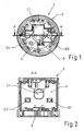
- a removable module 1 is listed with a total of four light emitting diodes or lightning elements or LED flashes D1 to D4.
- the interchangeable module 1 comprises an electrical circuit board 4, which comprises the LED flashes D1 to D4 or to which the LED flashes D1 to D4 are firmly fixed.
- the light-emitting diodes D1 to D4 in particular together or together, emit the light flash or the warning signal.
- the printed circuit board 4 receives its electrical energy by means of contacts 3.
- the contacts 3 are preferably formed with a corresponding change module 1 as compatible with other removable modules plug contacts, so that in an already conventional manner from a change module 1 to another infected at this change module both the electrical energy - As well as the electrical signal transmission or execution is carried out.
- the exchange module 1 in the example shown a holder 5 for the electrical circuit board 4 and a light bulb or the like, so that the removable module 1 universally formed to hold the circuit board 4 and to a non-illustrated, preferably a cylindrical socket comprising glow element or the like is.
- a flexible to a variety of components that is, electrical circuit boards 4 or light bulbs, etc., customizable change module 1, the production and the storage of warehouses, etc. corresponding Kalotten 2 or exchange modules 1 simplified.
- a capacitor C1 can be seen, which is used as a buffer for Caching of electrical energy for the flash of light to be generated or a warning signal to be generated with a plurality of short flashes of lightning is used.
- FIG. 3 shows by way of example an electronic circuit according to the invention.
- the contacts 3 and input terminals are connected in a manner not shown, for example, already commercially available machine controls, such as PLCs or the like.
- a power supply 6 includes, for example, a rectifier and in particular a supply unit for a control part 7.
- the control part 7 is designed in particular for controlling the time duration and / or intensity level and / or diagnosis. This means that with the help of the control part 7 on the one hand, the duration of the flash or the multiple lightning flashes warning signal, the brightness or intensity of the individual flash of light and the course of the intensity and a self-diagnosis of the circuit or the LED flashes D1 to D4 changeable / adjustable or realizable.
- the capacitor C1 is designed as a storage unit according to the invention for storing at least part of the light flash energy or warning signal energy for the light-emitting diodes D1 to D4.
- a switching or control unit 8 is shown in an advantageous manner, especially for current limiting or control with an advantageous electronic switch for the light emitting diodes D1 to D4.
- an advantageous electronic switch for the light emitting diodes D1 to D4 By way of example only the diode D1 and D2 is shown in FIG. 3 for reasons of clarity.
Abstract
Description
Die Erfindung betrifft ein Blitzlicht-Warnleuchtgerät zur Anzeige von wenigstens einem Betriebszustand von einem technischen Gerät wie einer Maschine, einer Anlage, eines Fahrzeugs oder dergleichen nach dem Oberbegriff des Anspruchs 1.The invention relates to a flashlight warning light device for displaying at least one operating state of a technical device such as a machine, a system, a vehicle or the like according to the preamble of
Warnleuchtgeräte, insbesondere Blitzlicht-Warnleuchtgeräte, sind zum Signalisieren bzw. Anzeigen von Betriebszuständen an technischen Geräten wie Maschinen, Anlagen oder Fahrzeugen vielfach im Einsatz. Sie dienen vor allem dazu, Betriebsstörungen von Maschinen oder Anlagen insbesondere optisch und/oder akustisch zu signalisieren, so dass das Bedienpersonal in der Lage ist, diese zu erkennen und zu beseitigen. Hierzu strahlen diese, gegebenenfalls neben einem oder mehreren Dauerlichtern und/oder einem akustischen Signal, einen Lichtblitz ab, der sich rundum bzw. bezogen auf die Längsachse der Leuchtsäule quer und um 360° ausbreitet.Warning light devices, in particular flashing light warning lights, are frequently used for signaling or displaying operating states on technical devices such as machines, systems or vehicles. Above all, they serve to signal malfunction of machines or systems, in particular optically and / or acoustically, so that the operating personnel are able to recognize and eliminate them. For this purpose, these radiate, optionally in addition to one or more continuous lights and / or an acoustic signal from a flash of light, which spreads across and around the longitudinal axis of the light column transversely and by 360 °.
Weiterhin können derartige Warnleuchtsäulen auch Betriebszustände signalisieren, von denen Gefahren für die Umgebung bzw. für Personen in der Umgebung ausgehen.Furthermore, such warning light columns can also signal operating states, of which threats to the Environment or for people in the area.
Für die Erzeugung eines Blitzlichtes wurden bislang Blitzröhren, insbesondere Xenonröhren, eingesetzt.Flash tubes, in particular xenon tubes, have hitherto been used to generate a flashlight.
Nachteilig bei derartigen Blitzröhren ist jedoch u.a. der vergleichsweise hohe Wartungsaufwand, der durch defekte Röhren entsteht.However, a disadvantage of such flash tubes u.a. the comparatively high maintenance required by defective tubes.
Aufgabe der Erfindung ist es demgegenüber, ein Blitzlicht-Warnleuchtgerät zur Anzeige von wenigstens einem Betriebszustand von einem technischen Gerät wie einer Maschine, einer Anlage, eines Fahrzeugs oder dergleichen mit einer wenigstens einem Blitzlichtelement umfassenden Blitzlichtvorrichtung zum Erzeugen von wenigstens einem Lichtblitz, vorzuschlagen, wobei der Aufwand für Wartung bzw. Reparatur deutlich verringert wird.The object of the invention is in contrast to propose a flashing light warning device for displaying at least one operating state of a technical device such as a machine, a system, a vehicle or the like with a flashlight device comprising at least one flashlight device for generating at least one flash of light, wherein the Cost of maintenance or repair is significantly reduced.
Diese Aufgabe wird, ausgehend von einem Blitzlicht-Warnleuchtgerät der einleitend genannten Art, durch die kennzeichnenden Merkmale des Anspruchs 1 gelöst. Durch die in den Unteransprüchen genannten Maßnahmen sind vorteilhafte Ausführungen und Weiterbildungen der Erfindung möglich.This object is achieved on the basis of a flashing warning light of the aforementioned type, by the characterizing features of
Dementsprechend zeichnet sich ein erfindungsgemäße Blitzlicht-Warnleuchtgerät dadurch aus, dass das Blitzlichtelement als Leuchtdiode ausgebildet ist und dass eine elektrische Kontrolleinheit zur Kontrolle einer zeitlichen Änderung der Helligkeit der Leuchtdiode vorgesehen ist.Accordingly, a flashlight warning light according to the invention is characterized in that the flash element is designed as a light emitting diode and that an electrical control unit for controlling a change in the brightness of the light emitting diode is provided.
Durch die Verwendung einer Leuchtdiode als das Blitzlichtelement des Blitzlichtsignalsgerätes wird es möglicht, während der Lebensdauer des technischen Gerätes das Blitzlichtelement bzw. die Leuchtdiode nicht mehr auszutauschen bzw. zu warten.By using a light emitting diode as the The flashlight element of the flashlight signal device makes it possible to replace the flash element or the light-emitting diode during the life of the technical device no longer or to maintain.
Beispielsweise weist eine vorteilhafte Leuchtdiode eine Lebensdauer von ca. 50 000 Betriebsstunden auf, was weit mehr als die Lebensdauer entsprechender technischer Geräte wie Produktionsanlagen oder dergleichen ist. Dementsprechend kann ein Blitzlicht-Warnleuchtgerät gemäß der Erfindung besonders wirtschaftlich günstig betrieben bzw. eingesetzt werden.For example, an advantageous light-emitting diode has a service life of approximately 50,000 operating hours, which is far longer than the service life of corresponding technical devices such as production systems or the like. Accordingly, a flashlight warning light according to the invention can be operated or used particularly economically favorable.
Darüber hinaus zeichnen sich erfindungsgemäße Blitzlicht-Warnleuchtgeräte bzw. Leuchtdioden dadurch aus, dass diese im Vergleich zu bisherigen Blitzröhren wesentlich erschütterungsunempfindlicher sind. Gerade bei Produktionsanlagen, Maschinen; Fahrzeugen oder dergleichen treten sehr häufig im Betrieb Erschütterungen auf, was die Lebensdauer bisheriger Blitzröhren beschränkte. Bei letzteren ist der Stromverbrauch im Vergleich zu erfindungsgemäßen Leuchtdioden deutlich höher, so dass auch eine wirtschaftlich günstige Energieversorgung bzw. umweltfreundliche Betriebsweise eines erfindungsgemäßen Blitzlicht-Warnleuchtgerätes realisiert wird.In addition, flashlight warning light devices or light-emitting diodes according to the invention are distinguished by the fact that they are considerably less susceptible to vibration than previous flash tubes. Especially in production plants, machines; Vehicles or the like occur very often in operation shocks, which limited the life of previous flash tubes. In the latter, the power consumption compared to light-emitting diodes according to the invention is significantly higher, so that an economically favorable energy supply or environmentally friendly operation of a flashlight warning light according to the invention is realized.
Dadurch, dass die Leuchtdiode während der Lebensdauer des entsprechenden technischen Gerätes nicht mehr ausgetauscht werden muss, kann beispielsweise die Leuchtdiode derart im Blitzlicht-Warnleuchtgerät fixiert bzw. gehalten werden, dass eine unlösbare Fixierung, wie beispielsweise eine Verlötung oder dergleichen, umgesetzt werden kann. Eine entsprechende Verlötung der erfindungsgemäßen Leuchtdiode kann vorzugsweise vollautomatisch hergestellt werden, so dass sich im Vergleich zum Stand der Technik, bei dem eine Blitzröhre in eine lösbare, spezielle Haltevorrichtung eingebunden wurde, eine deutlich einfachere und kostengünstigere Herstellung gemäß der Erfindung ergibt.Due to the fact that the light-emitting diode no longer needs to be replaced during the life of the corresponding technical device, the light-emitting diode can be fixed or held in the flashlight warning light fixture such that an insoluble fixation, such as a soldering or the like, can be implemented. A corresponding soldering of the light-emitting diode according to the invention can preferably be produced fully automatically, so that in comparison to the prior art, in which a flash tube was incorporated into a detachable, special holding device, a much simpler and more cost-effective production according to of the invention.
Gemäß der Erfindung ist zudem eine elektrische Kontrolleinheit zur Kontrolle einer zeitlichen Änderung der Helligkeit der Leuchtdiode vorgesehen. Hiermit ist ein vorteilhafter Intensitätsverlauf der Leuchtdiode während einer Anzeige- bzw. Blitzphase realisierbar. Beispielsweise kann eine impulsartige Änderung der Helligkeit verwirklicht werden. Dies bedeutet insbesondere, dass vergleichsweise kurzzeitig eine sehr hohe Intensität der Helligkeit der Leuchtdiode realisiert wird. Mit dieser Maßnahme kann eine Erhöhung der Wirkung der Signalisierung bzw. des Blitzlichtes erreicht werden, wodurch der zu signalisierende Betriebszustand durch entsprechende Personen besser wahrnehmbar wird.According to the invention, an electrical control unit is also provided for controlling a change over time of the brightness of the light-emitting diode. Hereby, an advantageous intensity profile of the light-emitting diode during a display or flash phase can be realized. For example, a pulse-like change in brightness can be realized. This means, in particular, that a comparatively short time, a very high intensity of the brightness of the light emitting diode is realized. With this measure, an increase in the effect of the signaling or the flashlight can be achieved, whereby the operating state to be signaled by appropriate persons is better perceived.
In vorteilhafter Weise umfasst ein Warnsignal mehrere Lichtblitze. Mit entsprechend zahlreichen Lichtblitzen, die beispielsweise kurzzeitig hintereinander verwirklicht werden, wird die Wahrnehmbarkeit durch bzw. Aufmerksamkeit entsprechender Personen und damit die Anzeige des Betriebszustandes des technischen Gerätes ebenfalls bzw. weiter verbessert.Advantageously, a warning signal comprises a plurality of flashes of light. With correspondingly numerous flashes of light, which are realized, for example, for a short time in succession, the perceptibility by or attention of corresponding persons and thus the display of the operating state of the technical device is also or further improved.
In einer vorteilhaften Ausführungsform der Erfindung weist die Kontrolleinheit wenigstens einen Energiespeicher zur Speicherung wenigstens eines Teils der elektrischen Energie für den Lichtblitz oder für das Warnsignal auf. Mit Hilfe des vorteilhaften Energiespeichers kann die elektrische Energie des Lichtblitzes bzw. des Warnsignals beispielsweise autark von einer weiteren bzw. kontinuierlichen Energiequelle betrieben werden und/oder zusätzlich zu einer zweiten bzw. kontinuierlichen Energiequelle verwendet werden.In an advantageous embodiment of the invention, the control unit has at least one energy store for storing at least part of the electrical energy for the flash of light or for the warning signal. With the help of the advantageous energy storage device, the electrical energy of the flash of light or the warning signal can for example be operated autonomously by a further or continuous energy source and / or used in addition to a second or continuous energy source.
Gegebenenfalls wird eine Batterie und/oder ein Akku als Energiespeicher verwendet. Vorzugsweise ist der Energiespeicher als Kondensator ausgebildet. Ein erfindungsgemäßer Kondensator kann nahezu beliebig häufig auf- und entladen werden, so dass eine Wartung des Energiespeichers entfallen kann, was wiederum den Betrieb des Blitzlicht-Warnleuchtgerätes gemäß der Erfindung verbessert.Optionally, a battery and / or a battery is used as energy storage. Preferably, the Energy storage designed as a capacitor. A capacitor according to the invention can be charged and discharged almost as often as desired so that maintenance of the energy store can be dispensed with, which in turn improves the operation of the flashlight warning light device according to the invention.
In einer bevorzugten Variante der Erfindung ist vor einer den Lichtblitz oder das Warnsignal umfassenden Anzeigephase eine den Energiespeicher auffüllende Speicherphase vorgesehen. Gegebenenfalls ist die Speicherphase nach dem Auftreten des anzuzeigenden Betriebszustandes des technischen Gerätes bzw. nach dem Erfassen des zu detektierenden Betriebszustandes vorgesehen. Dies bedeutet, dass in vorteilhafter Weise nach dem Auftreten bzw. Detektieren des anzuzeigenden Betriebszustandes die den Energiespeicher auffüllende Speicherphase und daran anschließend die Anzeigephase mit dem erzeugten Lichtblitz bzw. Warnsignal vorgesehen ist. Vorteilhafterweise wird dies mit Hilfe der elektrischen Kontrolleinheit gemäß der Erfindung sowie insbesondere unter Zuhilfenahme eines vorteilhaften Sensors zur Erfassung des anzuzeigenden Betriebszustandes verwirklicht.In a preferred variant of the invention, a storage phase which fills the energy store is provided in front of a display phase comprising the flash of light or the warning signal. Optionally, the storage phase is provided after the occurrence of the operating state of the technical device to be displayed or after detection of the operating state to be detected. This means that, advantageously, after the occurrence or detection of the operating state to be displayed, the storage phase which fills the energy store and subsequently the display phase is provided with the generated light flash or warning signal. Advantageously, this is achieved by means of the electrical control unit according to the invention and in particular with the aid of an advantageous sensor for detecting the operating state to be displayed.
Mit Hilfe einer der vorgenannten Maßnahmen wird erreicht, dass beispielsweise eine kontinuierliche Energieversorgung des Blitzlicht-Warnleuchtgerätes mit vergleichsweise geringer Spannung und/oder geringem Strom verwendbar ist. Durch Addition einer kontinuierlich zugeführten Energie und der zwischengespeicherten Energie des Energiespeichers kann in der Anzeigenphase eine vergleichsweise große bzw. aufaddierte Energiemenge für den Lichtblitz bzw. das Warnsignal zur Verfügung gestellt werden. Beispielsweise kann hierdurch eine handelsübliche Energieversorgung für elektrische (Maschinen-) Steuerungen, wie z.B. eine SPS-Steuerung oder dergleichen, mit beispielsweise einem maximalen elektrischen Strom von etwa 500 mA zur Versorgung des Blitzlicht-Warnleuchtgerätes verwendet werden. Hierbei kann erreicht werden, dass zum Beispiel mit Hilfe der vorgenannten Maßnahme bzw. der vorteilhaften Speicherphase bzw. dem vorteilhaften Energiespeicher für das Blitzlicht bzw. das Warnsignal insgesamt etwa 1,8 Ampere zur Verfügung stehen. Dies bedeutet, dass beispielsweise für den Lichtblitz bzw. das Warnsignal, neben dem Versorgungsstrom von etwa 500 mA, zusätzlich durch den vorteilhaften Energiespeicher zumindest kurzzeitig ca. 1,3 Ampere bereitgestellt werden können. Dementsprechend kann in vorteilhafter Weise bei vergleichsweise geringer kontinuierlich zugeführter Versorgungsenergiemenge trotzdem ein sehr heller bzw. auffälliger Lichtblitz mit großem Energieaufwand erzeugt werden.With the aid of one of the aforementioned measures it is achieved that, for example, a continuous energy supply of the flashlight warning light device with comparatively low voltage and / or low current can be used. By adding a continuously supplied energy and the cached energy of the energy storage, a comparatively large or accumulated amount of energy for the flash of light or the warning signal can be made available in the advertising phase. For example, this may be a commercial power supply for electrical (machine) controls, such as a PLC or the like, for example, with a maximum electric current of about 500 mA used to power the flashlight warning light. This can be achieved that the Example with the aid of the aforementioned measure or the advantageous storage phase or the advantageous energy storage for the flash or the warning signal total about 1.8 amps are available. This means that, for example, for the flash of light or the warning signal, in addition to the supply current of about 500 mA, additionally at least for a short time approximately 1.3 amps can be provided by the advantageous energy storage. Accordingly, it is advantageously possible to generate a very bright or conspicuous flash of light with a high expenditure of energy, even with a comparatively small amount of supply energy supplied continuously.
Durch die Verwendung bereits üblicher Versorgungsspannungen für Steuerungen entsprechender technischer Geräte wie sie beispielsweise bei einer SPS-Steuerung vorhanden ist, wird eine besonders einfache Zusammenführung des Blitzlicht-Warnleuchtgerätes gemäß der Erfindung mit dem technischen Gerät realisierbar. Dies führt u.a. zu einer wirtschaftlich günstigen Umsetzung der Erfindung.By using already customary supply voltages for controls of corresponding technical devices such as those present in a PLC control, a particularly simple merging of the flashlight warning light according to the invention with the technical device can be realized. This leads u.a. to an economically favorable implementation of the invention.
Vorzugsweise weist die elektrische Kontrolleinheit eine vorteilhafte Steuerungs- bzw. Regelungsmöglichkeit auf, um die Speicherphase bzw. Anzeigephase vorteilhaft zu realisieren. Ganz besonders von Vorteil ist hierbei die Verwendung eines Mikroprozessors, um entsprechende Steuer- bzw. Regelvorgänge in vorteilhafter Weise umzusetzen.The electrical control unit preferably has an advantageous control or regulation possibility in order to advantageously realize the storage phase or display phase. Especially advantageous here is the use of a microprocessor to implement appropriate control or regulating operations in an advantageous manner.
In einer besonderen Weiterbildung der Erfindung ist wenigstens eine das Blitzlichtelemente fixierende und kontaktierende Leiterplatte in Richtung der Längsachse des Blitzlicht-Warnleuchtgerätes angeordnet. Es hat sich in der Praxis gezeigt, dass eine derartig ausgerichtete Leiterplatte mit daran fixiertem Blitzlichtelement besonders von Vorteil ist. Vorzugsweise ist auf beiden Seiten der Leiterplatte wenigstens ein Blitzlichtelement vorgesehen. Dies kann in besonders einfacher Weise ein im Wesentlichen voll umfängliches Abstrahlen des Lichtblitzes bzw. Warnsignals ermöglichen.In a particular development of the invention, at least one circuit board which fixes and contacts the flashlight elements is arranged in the direction of the longitudinal axis of the flashlight warning illuminator. It has been found in practice that such a oriented printed circuit board with it fixed flash element is particularly advantageous. Preferably, on both sides of the circuit board at least one flash element provided. In a particularly simple way, this can enable a substantially full circumferential emission of the light flash or warning signal.
Vor allem alternativ zur zuvor genannten Ausrichtung einer entsprechenden Leiterplatte kann diese auch quer, insbesondere etwa um 90°, zur Längsachse des Blitzlicht-Warnleuchtgerätes angeordnet werden. Dies ist ganz besonders von Vorteil, wenn eine Abstrahlung des Lichtblitzes bzw. Warnsignals (gegebenenfalls zusätzlich) im Wesentlichen in Richtung der Längsachse des Blitzlicht-Warnleuchtgerätes gewünscht sein sollte. Auch kann die Abstrahlung des Lichtblitzes durch vorteilhafte Anordnung der Leuchtdiode bzw. mehrerer Leuchtdioden auch mit dieser Leiterplattenanordnung über den gesamten Umfang erreicht werden.Above all, as an alternative to the aforementioned orientation of a corresponding circuit board, this can also be arranged transversely, in particular approximately at 90 °, to the longitudinal axis of the flashlight warning light device. This is particularly advantageous if a radiation of the flash of light or warning signal (possibly in addition) should be desired substantially in the direction of the longitudinal axis of the flashing light warning light. Also, the radiation of the flash of light can be achieved by advantageous arrangement of the light emitting diode or a plurality of light emitting diodes with this circuit board assembly over the entire circumference.
Grundsätzlich ist von Vorteil, eine Abstrahlung des Lichtblitzes bzw. des Warnsignals voll umfänglich bzw. rundum, dass heißt über ein Winkelbereich von 360°, zu verwirklichen. Hierdurch wird die Wahrnehmung des Lichtblitzes bzw. Warnsignals verbessert.Basically, it is advantageous to realize a radiation of the flash of light or of the warning signal fully circumferentially or completely, that is to say over an angular range of 360 °. As a result, the perception of the flash of light or warning signal is improved.
Vorteilhafterweise ist das Blitzlicht-Warnleuchtgerät als mehrstufiges Blitzlicht-Warnleuchtgerät mit wenigstens zwei unterschiedlichen Signalen ausgebildet. Beispielsweise kann das Blitzlicht-Warnleuchtgerät mehrere Anzeigestufen bzw. Anzeigevarianten aufweisen, insbesondere mit verschiedenen Farben und/oder mit einem akustischen Ton. Gegebenenfalls sind zusammenhängende Stufen, insbesondere in Form einer sogenannten Kompaktsäule, realisiert.Advantageously, the flashlight warning light is designed as a multi-stage flashlight warning light with at least two different signals. By way of example, the flashlight warning light device can have a plurality of display stages or display variants, in particular with different colors and / or with an acoustic tone. Optionally, contiguous stages, in particular in the form of a so-called compact column, are realized.
Vorzugsweise ist das Blitzlicht-Warnleuchtgerät als eine wenigstens ein, vorzugsweise mehrere Wechselmodule umfassende Signalsäule ausgebildet. Derartige Wechselmodule sind in vorteilhafter Weise dafür ausgebildet, dass diese einfach austauschbar sind.Preferably, the flashlight warning light is formed as a at least one, preferably more changeover modules signal tower. Such change modules are in advantageously designed so that they are easily replaceable.
Beispielsweise kann ein bereits handelsübliches Gehäuse für Wechselmodule zur Aufnahme bzw. Integration der das Blitzlichtelement umfassenden Blitzlichtvorrichtung gemäß der Erfindung verwendet werden. Gerade diese Variante der Erfindung bietet die Möglichkeit besonders einfach ein Nachrüsten bzw. Ausrüsten bislang handelsüblicher Warnleuchtsäulen bzw. Signalsäulen gemäß der Erfindung umzusetzen.For example, an already commercially available housing for exchange modules for the integration of the flashlight element comprising the flash device according to the invention can be used. Especially this variant of the invention offers the possibility particularly easy to retrofit or equip heretofore commercial warning light columns or signal towers implement according to the invention.
Vorteilhafterweise ist eine Haltevorrichtung zum insbesondere lösbaren Halten der elektrischen Leiterplatte vorgesehen. Vorzugsweise ist die Haltevorrichtung in einem Wechselmodul angeordnet bzw. integriert. Mit einer derartigen Haltevorrichtung können einerseits eine entsprechende Leiterplatte mit dem als Leuchtdiode ausgebildeten Blitzlichtelement bzw. mit mehreren Leuchtdioden separat vom Gehäuse des Wechselmodüls hergestellt und danach einfach in dieses integriert bzw. von diesem gehalten werden.Advantageously, a holding device is provided for releasably holding the electrical circuit board in particular. Preferably, the holding device is arranged or integrated in a removable module. With such a holding device, on the one hand, a corresponding printed circuit board with the light-emitting element designed as a light-emitting diode or with a plurality of light-emitting diodes can be manufactured separately from the housing of the exchange module and then simply integrated into it or held by it.
In einer besonderen Weiterbildung der Erfindung ist die Haltevorrichtung zum Halten der elektrischen Leiterplatte und zum Halten eines Leuchtelementes wie einer Glühbirne oder dergleichen ausgebildet. Hierdurch wird eine sogenannten Multifassung bzw. eine Fassung sowohl für eine elektrische Leiterplatte als auch für eine Glühbirne oder dergleichen realisiert, so dass die Haltevorrichtung bzw. ein derartig ausgestaltetes Wechselmodul für unterschiedlichste Anwendungsfälle flexibel einsetzbar ist.In a particular embodiment of the invention, the holding device for holding the electrical circuit board and for holding a light-emitting element such as a light bulb or the like is formed. As a result, a so-called Multifassung or a version is realized both for an electrical circuit board as well as for a light bulb or the like, so that the holding device or such a configured exchange module for a variety of applications can be used flexibly.
In vorteilhafter Weise ist eine Diagnoseeinheit zur Zustandsdiagnose des Blitzlichtelementes bzw. der oder den Leuchtdioden vorgesehen. Hiermit wird eine Selbstdiagnose bzw. eine Überwachung der Funktionsfähigkeit des Blitzlichtelementes bzw. der Leuchtdiode gemäß der Erfindung realisierbar. Entsprechend wird ein automatisches Erkennen fehlerhafter Leuchtdioden ermöglicht. Hierdurch ist eine besonders hohe Betriebssicherheit des Blitzlicht-Warnleuchtgerätes gemäß der Erfindung realisierbar.In an advantageous manner, a diagnostic unit is provided for the status diagnosis of the flashlight element or the light-emitting diode (s). This is a self-diagnosis or monitoring the functioning of the Flash element or the light emitting diode according to the invention realized. Accordingly, automatic detection of defective LEDs is made possible. As a result, a particularly high reliability of the flashlight warning light according to the invention can be realized.
Beispielsweise wird ein weißes Warnsignal bzw. ein weißer Lichtblitz erzeugt. Vorzugsweise ist der Lichtblitz oder das Warnsignal farbig. Hierfür kann beispielsweise die Leuchtdiode als farbige Leuchtdiode realisiert werden, zum Beispiel als rote, grüne, blaue oder gelbe LED. Eine Kalotte der Blitzlichtvorrichtung bzw. des Wechselmoduls kann dann z.B. klar oder gleichfarbig ausgebildet sein.For example, a white warning signal or a white flash of light is generated. Preferably, the flash of light or the warning signal is colored. For this purpose, for example, the light-emitting diode can be realized as a colored light-emitting diode, for example as a red, green, blue or yellow LED. A dome of the flashlight device or the exchange module can then be used e.g. be clear or the same color.
Bei einem weißen bzw. farblosen Blitzlichtelement bzw. LED wird in vorteilhafter Weise eine entsprechend farbige Kalotte verwendet.In the case of a white or colorless flashlight element or LED, a correspondingly colored dome is advantageously used.
Grundsätzlich wird durch die Erzeugung eines farbigen Lichtblitzes bzw. Warnsignals die Signalwirkung bzw. die Aufmerksamkeit für entsprechende Personen weiter verbessert.In principle, the signal effect or the attention for corresponding persons is further improved by the generation of a colored light flash or warning signal.
Ein Ausführungsbeispiel der Erfindung ist in der Zeichnung dargestellt und wird anhand der nachfolgenden Figuren näher erläutert.An embodiment of the invention is illustrated in the drawing and will be explained in more detail with reference to the following figures.
Im Einzelnen zeigt:
Figur 1- schematisch in Draufsicht ein Wechselmodul mit einem LED-Blitzlichtelement gemäß der Erfindung,
Figur 2- eine schematische Schnittdarstellung längs der Linie A-A gemäß Figur 1 und
Figur 3- ein schematisches Bockschaltbild mit LED-Blitz gemäß der Erfindung.
- FIG. 1
- schematically in plan view a change module with an LED flash element according to the invention,
- FIG. 2
- a schematic sectional view taken along the line AA of Figure 1 and
- FIG. 3
- a schematic block diagram with LED flash according to the invention.
In Figur 1 und 2 ist ein Wechselmodul 1 mit insgesamt vier Leuchtdioden bzw. Blitzelementen bzw. LED-Blitze D1 bis D4 aufgeführt. Neben einer Kalotte 2 umfasst das Wechselmodul 1 eine elektrische Leiterplatte 4, die die LED-Blitze D1 bis D4 umfasst bzw. an denen die LED-Blitze D1 bis D4 fest fixiert sind. Gemäß der Erfindung geben die Leuchtdioden D1 bis D4 insbesondere zusammen bzw. gemeinsam den Lichtblitz bzw. das Warnsignal ab.In Figures 1 and 2, a
Die Leiterplatte 4 erhält ihre elektrische Energie mittels Kontakte 3. Die Kontakte 3 sind vorzugsweise bei einem entsprechenden Wechselmodul 1 als zu weiteren Wechselmodulen kompatiblen Steckkontakte ausgebildet, so dass in bereits üblicher Weise von einem Wechselmodul 1 zu einem weiteren an diesem angesteckten Wechselmodul sowohl die elektrische Energie- als auch die elektrische Signalübertragung bzw. -durchführung erfolgt.The printed
Weiterhin weist das Wechselmodul 1 im dargestellten Beispiel eine Halterung 5 für die elektrische Leiterplatte 4 und eine Glühbirne oder dergleichen auf, so dass das Wechselmodul 1 universell zum Halten der Leiterplatte 4 und zu einem nicht näher dargestellten, vorzugsweise eine zylindrische Fassung umfassenden Glühelement oder dergleichen ausgebildet ist. Mit einem derartig flexibel an unterschiedlichste Komponenten, dass heißt elektrische Leiterplatten 4 oder Glühbirnen etc., anpassbaren Wechselmodul 1 vereinfacht sich die Herstellung als auch die Lagerhaltung etc. entsprechender Kalotten 2 bzw. Wechselmodule 1.Furthermore, the
Darüber hinaus ist in den Figuren 1 und 2 ein Kondensator C1 zu entnehmen, der als Zwischenspeicher zur Zwischenspeicherung elektrischer Energie für den zu erzeugenden Lichtblitz bzw. ein zu erzeugendes Warnsignal mit mehreren kurz hintereinander folgenden Lichtblitzen verwendet wird.In addition, in Figures 1 and 2, a capacitor C1 can be seen, which is used as a buffer for Caching of electrical energy for the flash of light to be generated or a warning signal to be generated with a plurality of short flashes of lightning is used.
In Figur 3 ist beispielhaft eine elektronische Schaltung gemäß der Erfindung dargestellt. Die Kontakte 3 bzw. Eingangsklemmen sind in nicht näher dargestellter Weise beispielsweise an bereits handelsübliche Maschinensteuerungen, wie zum Beispiel SPS-Steuerungen oder dergleichen, anschließbar. Eine Stromversorgung 6 umfasst beispielsweise einen Gleichrichter und insbesondere eine Versorgungseinheit für ein Steuerteil 7. Das Steuerteil 7 ist insbesondere zur Steuerung der Zeitdauer und/oder Intensitätshöhe und/oder Diagnose ausgebildet. Dies bedeutet, dass mit Hilfe des Steuerteils 7 einerseits die Zeitdauer des Lichtblitzes bzw. des mehrere Lichtblitze umfassenden Warnsignals, die Helligkeit bzw. Intensität des einzelnen Lichtblitzes sowie der Verlauf der Intensität als auch eine Selbstdiagnose der Schaltung bzw. der LED-Blitze D1 bis D4 veränderbar/einstellbar bzw. realisierbar ist.FIG. 3 shows by way of example an electronic circuit according to the invention. The
Weiterhin ist der Kondensator C1 als Speichereinheit gemäß der Erfindung zur Speicherung wenigstens eines Teils der Lichtblitzenergie bzw. Warnsignalenergie für die Leuchtdioden D1 bis D4 ausgebildet.Furthermore, the capacitor C1 is designed as a storage unit according to the invention for storing at least part of the light flash energy or warning signal energy for the light-emitting diodes D1 to D4.
Eine Schalt- bzw. Steuereinheit 8 ist in vorteilhafter Weise vor allem zur Strombegrenzung bzw. Regelung mit einem vorteilhaften elektronischen Schalter für die Leuchtdioden D1 bis D4 dargestellt. Beispielhaft ist in Figur 3 lediglich die Diode D1 und D2 aus Gründen der Übersichtlichkeit dargestellt.A switching or control unit 8 is shown in an advantageous manner, especially for current limiting or control with an advantageous electronic switch for the light emitting diodes D1 to D4. By way of example only the diode D1 and D2 is shown in FIG. 3 for reasons of clarity.
Claims (14)
Applications Claiming Priority (1)
| Application Number | Priority Date | Filing Date | Title |
|---|---|---|---|
| DE102006015175A DE102006015175B4 (en) | 2006-03-30 | 2006-03-30 | Flash warning light device |
Publications (2)
| Publication Number | Publication Date |
|---|---|
| EP1840853A2 true EP1840853A2 (en) | 2007-10-03 |
| EP1840853A3 EP1840853A3 (en) | 2009-10-21 |
Family
ID=38460246
Family Applications (1)
| Application Number | Title | Priority Date | Filing Date |
|---|---|---|---|
| EP07006457A Withdrawn EP1840853A3 (en) | 2006-03-30 | 2007-03-29 | Warning signal lamp with flash |
Country Status (2)
| Country | Link |
|---|---|
| EP (1) | EP1840853A3 (en) |
| DE (1) | DE102006015175B4 (en) |
Families Citing this family (6)
| Publication number | Priority date | Publication date | Assignee | Title |
|---|---|---|---|---|
| DE102007052377B4 (en) | 2007-10-31 | 2015-04-02 | Werma Holding Gmbh + Co. Kg | Warning light for visual display of at least one operating state |
| DE102011080595B4 (en) * | 2011-08-08 | 2014-05-15 | Compro Electronic Gmbh | Light signal module |
| US9087441B2 (en) * | 2011-12-02 | 2015-07-21 | Utc Fire & Security Corporation | Notification appliance circuit with energy storing notification devices |
| EP2701132B1 (en) | 2012-08-23 | 2018-07-04 | Novar GmbH | Alarm device having a local energy storage unit, and bus-based alarm system |
| DE102013112127A1 (en) | 2013-11-05 | 2015-05-07 | Eaton Electrical Ip Gmbh & Co. Kg | Multicolor signal arrangement, method for defining modes of a multi-color signal arrangement and system, comprising a multicolor signal arrangement and an RFID transmitter |
| DE102015001895A1 (en) * | 2015-02-18 | 2016-08-18 | Werma Holding Gmbh + Co. Kg | Signal device, in particular signal tower |
Citations (5)
| Publication number | Priority date | Publication date | Assignee | Title |
|---|---|---|---|---|
| WO1997029320A1 (en) * | 1996-02-09 | 1997-08-14 | Aktiiviaudio Oy | Flight obstacle light |
| US20040105264A1 (en) * | 2002-07-12 | 2004-06-03 | Yechezkal Spero | Multiple Light-Source Illuminating System |
| US20040207532A1 (en) * | 2003-04-18 | 2004-10-21 | Smithson Bradley D. | Temperature compensated warning light |
| US20040212420A1 (en) * | 2003-04-28 | 2004-10-28 | Toko Kabushiki Kaisha | Switching constant-current power device |
| US20050219060A1 (en) * | 2004-04-01 | 2005-10-06 | Curran John W | Method and apparatus for providing a notification appliance with a light emitting diode |
Family Cites Families (8)
| Publication number | Priority date | Publication date | Assignee | Title |
|---|---|---|---|---|
| ATE161083T1 (en) * | 1994-04-15 | 1997-12-15 | Werma Signalgeraete Gmbh & Co | SIGNAL COLUMN |
| DE19624087A1 (en) * | 1996-06-17 | 1997-12-18 | Wendelin Pimpl | LED illumination apparatus for colour system |
| US6456205B1 (en) * | 1998-05-21 | 2002-09-24 | Thales Optronics (Taunton) Ltd | Anti-collision warning lights and method of use |
| DE19916238C2 (en) * | 1999-04-10 | 2003-11-20 | Was Elektronik Gmbh | Beacon arrangement for emergency vehicles |
| DE10041201A1 (en) * | 2000-08-23 | 2002-03-07 | Lmg Signaltechnologie Kg | Multiple aspect signal column with flashing segment has current and voltage detectors for monitoring flash capacitor |
| US6483254B2 (en) * | 2000-12-20 | 2002-11-19 | Honeywell International Inc. | Led strobe light |
| DE20220650U1 (en) * | 2002-03-22 | 2004-01-08 | Werma Signaltechnik Gmbh + Co. Kg | Signal tower for various signaling applications has LEDs, each associated with one of at least two segments of different colors with LEDs of different segments being separately controlled |
| DE102004004839A1 (en) * | 2004-01-30 | 2005-08-18 | Siemens Ag | Arrangement with at least one LED and application of this arrangement |
-
2006
- 2006-03-30 DE DE102006015175A patent/DE102006015175B4/en active Active
-
2007
- 2007-03-29 EP EP07006457A patent/EP1840853A3/en not_active Withdrawn
Patent Citations (5)
| Publication number | Priority date | Publication date | Assignee | Title |
|---|---|---|---|---|
| WO1997029320A1 (en) * | 1996-02-09 | 1997-08-14 | Aktiiviaudio Oy | Flight obstacle light |
| US20040105264A1 (en) * | 2002-07-12 | 2004-06-03 | Yechezkal Spero | Multiple Light-Source Illuminating System |
| US20040207532A1 (en) * | 2003-04-18 | 2004-10-21 | Smithson Bradley D. | Temperature compensated warning light |
| US20040212420A1 (en) * | 2003-04-28 | 2004-10-28 | Toko Kabushiki Kaisha | Switching constant-current power device |
| US20050219060A1 (en) * | 2004-04-01 | 2005-10-06 | Curran John W | Method and apparatus for providing a notification appliance with a light emitting diode |
Also Published As
| Publication number | Publication date |
|---|---|
| DE102006015175B4 (en) | 2013-01-17 |
| EP1840853A3 (en) | 2009-10-21 |
| DE102006015175A1 (en) | 2007-10-04 |
Similar Documents
| Publication | Publication Date | Title |
|---|---|---|
| DE102006015175B4 (en) | Flash warning light device | |
| EP2056268B1 (en) | Warning light for the visual display of at least one operating status | |
| DE202006013053U1 (en) | Light-emitting device has array of LEDs in a body with optical processing element to give uniform light emission | |
| DE202006013055U1 (en) | Heat dispersion or heat sink module for dispersing heat from light emission elements in a light emitting device such as a lamp | |
| DE202006013052U1 (en) | Light-emitting device has body with heat-dissipating base on one side and many light-emitting elements on a circuit board with connecting leads through the heat-dissipating base | |
| DE202006019347U1 (en) | Arrangement for controlling a LED rotating beacon | |
| EP2911919B1 (en) | Motor vehicle having a lamp in an antenna device for signalling the operating condition of a safety installation | |
| DE102009052690B3 (en) | Method for driving LED-lamp of electrical system of e.g. commercial vehicle, involves providing measured flow current as control value to booster, and regulating additional load by measured flow current that is supplied to battery | |
| DE102016204370A1 (en) | Infrared light for a vehicle | |
| EP1684001A1 (en) | Lighting device | |
| DE10227117A1 (en) | diving lamp | |
| DE202006013054U1 (en) | Optical processing element e.g., for light emission device, has arcuate pattern on first- and second-faces with different radius | |
| DE4324779A1 (en) | Signal display indicating malfunction of bicycle's lamps - has green LED electrically in series with rear lamp and mounted on headlamp casing | |
| DE102011010681A1 (en) | Exchangeable device for producing light in guiding and leading lights or traffic signal system, particularly in marine system or air system or rail system, comprises temperature controller for temperature regulation of light emitting diode | |
| WO2000051403A1 (en) | Led low energy lamp system mounted on a common screw cap and plug-in cap | |
| EP3330592A1 (en) | Transportable and portable lamp and method for switching such a lamp | |
| DE102006061808B3 (en) | LED-rotating beacon controlling arrangement for e.g. police emergency vehicle, has evaluation-and control unit for automatic selection of rotary- or flash-light operation based on information about visible-relevant environmental conditions | |
| DE102009002696A1 (en) | Parking light function implemented lighting device for bicycle, has front and rear lights provided with lighting units and control unit that is provided as component spatially separated from lights | |
| DE202017105794U1 (en) | Infrared light for a vehicle | |
| EP1178706A2 (en) | Lighting device | |
| DE102008020998A1 (en) | Intrinsically safe headlight | |
| EP3307023A1 (en) | Operating device for light with output of status information in particular for fault analysis | |
| DE202018105186U1 (en) | Optical signaling device with a dome and a terminating element | |
| EP3022809B1 (en) | Plug device | |
| WO2009006995A2 (en) | Motor vehicle light system |
Legal Events
| Date | Code | Title | Description |
|---|---|---|---|
| PUAI | Public reference made under article 153(3) epc to a published international application that has entered the european phase |
Free format text: ORIGINAL CODE: 0009012 |
|
| AK | Designated contracting states |
Kind code of ref document: A2 Designated state(s): AT BE BG CH CY CZ DE DK EE ES FI FR GB GR HU IE IS IT LI LT LU LV MC MT NL PL PT RO SE SI SK TR |
|
| AX | Request for extension of the european patent |
Extension state: AL BA HR MK YU |
|
| RAP1 | Party data changed (applicant data changed or rights of an application transferred) |
Owner name: WERMA HOLDING GMBH + CO. KG |
|
| RIC1 | Information provided on ipc code assigned before grant |
Ipc: G08B 29/24 20060101ALI20090624BHEP Ipc: G08B 5/38 20060101AFI20070705BHEP |
|
| PUAL | Search report despatched |
Free format text: ORIGINAL CODE: 0009013 |
|
| AK | Designated contracting states |
Kind code of ref document: A3 Designated state(s): AT BE BG CH CY CZ DE DK EE ES FI FR GB GR HU IE IS IT LI LT LU LV MC MT NL PL PT RO SE SI SK TR |
|
| AX | Request for extension of the european patent |
Extension state: AL BA HR MK RS |
|
| 17P | Request for examination filed |
Effective date: 20100226 |
|
| AKX | Designation fees paid |
Designated state(s): DE FR GB IT |
|
| 17Q | First examination report despatched |
Effective date: 20110301 |
|
| STAA | Information on the status of an ep patent application or granted ep patent |
Free format text: STATUS: THE APPLICATION HAS BEEN WITHDRAWN |
|
| 18W | Application withdrawn |
Effective date: 20120530 |