EP1840613A1 - Optical option attachment ring - Google Patents
Optical option attachment ring Download PDFInfo
- Publication number
- EP1840613A1 EP1840613A1 EP07006264A EP07006264A EP1840613A1 EP 1840613 A1 EP1840613 A1 EP 1840613A1 EP 07006264 A EP07006264 A EP 07006264A EP 07006264 A EP07006264 A EP 07006264A EP 1840613 A1 EP1840613 A1 EP 1840613A1
- Authority
- EP
- European Patent Office
- Prior art keywords
- lens barrel
- rotator
- ring body
- fastening screw
- abutting surface
- Prior art date
- Legal status (The legal status is an assumption and is not a legal conclusion. Google has not performed a legal analysis and makes no representation as to the accuracy of the status listed.)
- Granted
Links
- 230000003287 optical effect Effects 0.000 title claims abstract description 48
- 230000007423 decrease Effects 0.000 claims description 4
- 229920006324 polyoxymethylene Polymers 0.000 description 2
- 229930182556 Polyacetal Natural products 0.000 description 1
- 239000004809 Teflon Substances 0.000 description 1
- 229920006362 Teflon® Polymers 0.000 description 1
- 229920005989 resin Polymers 0.000 description 1
- 239000011347 resin Substances 0.000 description 1
- 229920003002 synthetic resin Polymers 0.000 description 1
- 239000000057 synthetic resin Substances 0.000 description 1
Images



Classifications
-
- G—PHYSICS
- G02—OPTICS
- G02B—OPTICAL ELEMENTS, SYSTEMS OR APPARATUS
- G02B7/00—Mountings, adjusting means, or light-tight connections, for optical elements
- G02B7/02—Mountings, adjusting means, or light-tight connections, for optical elements for lenses
- G02B7/14—Mountings, adjusting means, or light-tight connections, for optical elements for lenses adapted to interchange lenses
-
- G—PHYSICS
- G02—OPTICS
- G02B—OPTICAL ELEMENTS, SYSTEMS OR APPARATUS
- G02B15/00—Optical objectives with means for varying the magnification
- G02B15/02—Optical objectives with means for varying the magnification by changing, adding, or subtracting a part of the objective, e.g. convertible objective
-
- G—PHYSICS
- G03—PHOTOGRAPHY; CINEMATOGRAPHY; ANALOGOUS TECHNIQUES USING WAVES OTHER THAN OPTICAL WAVES; ELECTROGRAPHY; HOLOGRAPHY
- G03B—APPARATUS OR ARRANGEMENTS FOR TAKING PHOTOGRAPHS OR FOR PROJECTING OR VIEWING THEM; APPARATUS OR ARRANGEMENTS EMPLOYING ANALOGOUS TECHNIQUES USING WAVES OTHER THAN OPTICAL WAVES; ACCESSORIES THEREFOR
- G03B17/00—Details of cameras or camera bodies; Accessories therefor
- G03B17/56—Accessories
- G03B17/565—Optical accessories, e.g. converters for close-up photography, tele-convertors, wide-angle convertors
-
- G—PHYSICS
- G03—PHOTOGRAPHY; CINEMATOGRAPHY; ANALOGOUS TECHNIQUES USING WAVES OTHER THAN OPTICAL WAVES; ELECTROGRAPHY; HOLOGRAPHY
- G03B—APPARATUS OR ARRANGEMENTS FOR TAKING PHOTOGRAPHS OR FOR PROJECTING OR VIEWING THEM; APPARATUS OR ARRANGEMENTS EMPLOYING ANALOGOUS TECHNIQUES USING WAVES OTHER THAN OPTICAL WAVES; ACCESSORIES THEREFOR
- G03B17/00—Details of cameras or camera bodies; Accessories therefor
- G03B17/56—Accessories
- G03B17/566—Accessory clips, holders, shoes to attach accessories to camera
Definitions
- the present invention relates to an optical option attachment ring, and particularly to an optical option attachment ring that will not disengage until and after a fastening screw is tightened.
- the optical option attachment ring 10' includes one end 21' and the other end 22' disposed with a predetermined gap therebetween, a ring body 20' that connects the one end 21' to the other end 22' and receives a lens barrel (not shown), and a fastening screw 23' that is inserted into screw holes 21a' and 22a' that pass through the one end 21' and the other end 22'.
- the optical option attachment ring is configured such that tightening the fastening screw 23' brings the one end 21' and the other end 22' closer to each other and hence the diameter of the ring body 20' decreases so that the optical option attachment ring 10' is fastened to the lens barrel, while loosing fastening screw 23' separates the one end 21' and the other end 22' from each other and hence the diameter of the ring body 20' increases so that the optical option attachment ring 10' disengages from the lens barrel.
- the one end 21' and the other end 22' of the optical option attachment ring 10' have inclined portions, and tightening the fastening screw 23' moves a part 22b' of the other end 22' along the inclined surface of the one end 21', so that the part 22b' projects inward from the inner circumferential surface 20a' of the ring body 20' and is situated (engaged) in a groove (now shown) formed in the lens barrel.
- the present invention has been made in view of such circumstances and aims to prevent disengagement of the optical option attachment ring until and after the fastening screw is tightened.
- a first aspect of the present invention is an optical option attachment ring including one end and the other end disposed with a predetermined gap therebetween, a ring body that connects the one end to the other end and receives a lens barrel, and a fastening screw that is inserted into screw holes that pass through the one end and the other end.
- the optical option attachment ring is configured such that tightening the fastening screw brings the one end and the other end closer to each other and hence the diameter of the ring body decreases so that the optical option attachment ring is fastened to the lens barrel, while loosening the fastening screw separates the one end and the other end from each other and hence the diameter of the ring body increases so that the optical option attachment ring disengages from the lens barrel.
- the optical option attachment ring further includes a rotator having an abutting surface that projects inward from the inner circumferential surface of the ring body and abuts the front end of the lens barrel as well as an arcuate portion that follows the upper end of the abutting surface.
- the optical option attachment ring further includes a resilient member that applies an urging force to the rotator such that the rotator rotates in the direction opposite to the above-mentioned rotation direction, and a stopper that abuts at least one of the one end and the other end so as to restrict the rotation caused by the urging force of the resilient member.
- the urging force of the resilient member counter-rotates the rotator so that the abutting surface and the arcuate portion will be situated in the groove formed in the lens barrel. That is, the arcuate portion engages the groove. It is therefore possible to prevent the disengagement of the optical option attachment ring until and after the fastening screw is tightened.
- a second aspect of the present invention is the optical option attachment ring according to the first aspect configured such that the rotator is provided with an opening into which the fastening screw is inserted, and the rotator is disposed between the one end and the other end and rotatably held around the inserted fastening screw.
- the fastening screw also serves as the axis of rotation of the rotator, there is no need to separately provide an axis of rotation of the rotator.
- a third aspect of the present invention is the optical option attachment ring according to the first or second aspect configured such that the rotator has a small arcuate portion that follows the lower end of the abutting surface and is smaller than the arcuate portion.
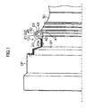
- Figs. 1 and 2 explain the configuration of the optical option attachment ring according to the present invention.
- an optical option attachment ring 10 is a structure for mount an optical option OP, such as a wide-converter and a tele-converter, to a lens barrel 30.
- the optical option attachment ring 10 includes one end 21 and the other end 22 disposed with a predetermined gap therebetween and a ring body 20 that connects the one end 21 to the other end 22.
- the inner diameter of the ring body 20 is designed to be slightly larger than the outer diameter of (the front end of) the lens barrel 30, so that the lens barrel 30 can be inserted into the ring body 20 and moved to a predetermined position (intended mounting position).
- the one end 21 and the other end 22 are provided with screw holes 21a and 22a that pass through the one end 21 and the other end 22.
- a fastening screw 23 is inserted into the screw holes 21a and 22a.
- the screw hole 21a in the one end 21 includes a large-diameter hole 21a1, a step 21a2 that follows the large-diameter hole 21a1 and a small-diameter hole 21a3 that follows the step 21a2.
- a screw body 23a of the fastening screw 23 is situated in the large-diameter hole 21a1, and a threaded portion 23b formed on one end of the screw body 23a is situated in the small-diameter hole 21a3.
- a step 23c is formed at the boundary between the screw body 23a and the threaded portion 23b.
- the step 23c abuts the step 21a2 of the screw hole 21a, so that the step 23c prevents the fastening screw 23 from being inserted any further.
- a thread groove in which the threaded portion 23b of the fastening screw 23 is screwed is formed in a threaded hole 22a in the other end 22.
- the knob 23d of the fastening screw 23 is rotated in the direction in which the fastening screw 23 is loosened, the one end 21 and the other end 22 are relatively separated from each other, so that the diameter of the ring body 20 increases.
- the diameter of the optical option attachment ring 10 returns to its initial value. That is, the optical option attachment ring 10 is unfastened from the lens barrel 30.
- the optical option attachment ring 10 includes an anti-disengagement member 40 (corresponding to a rotator of the present invention).
- the anti-disengagement member 40 can be made of, for example, polyacetal resin (POM), Teflon ® or other synthetic resins.
- POM polyacetal resin
- Teflon ® Teflon ®
- the anti-disengagement member 40 is a plate-like member and includes an abutting surface 41 that abuts the front end 31 of the lens barrel 30 when the lens barrel 30 is inserted.
- a large-diameter portion 42 (corresponding to an arcuate portion of the present invention) is provided such that it follows the upper end of the abutting surface 41, while a small-diameter portion 43 is provided such that it follows the lower end of the abutting surface 41.
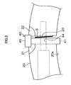
- the anti-disengagement member 40 is disposed between the one end 21 and the other end 22, and the fastening screw 23 is inserted into an opening 44 formed at the center of the anti-disengagement member 40 to rotatably hold the anti-disengagement member 40 around the fastening screw 23. Since the fastening screw 23 also serves as the axis of rotation of the anti-disengagement member 40, there is no need to separately provide an axis of rotation of the anti-disengagement member 40.
- the anti-disengagement member 40 is connected to the other end 22 via a resilient member B (for example, part of a coil spring).
- the resilient member B is a member for applying an urging force to the anti-disengagement member 40 such that the anti-disengagement member 40 is rotated counterclockwise in Fig. 1.
- the anti-disengagement member 40 is provided with a stopper 45, and the stopper 45 abuts the one end 21 and the other end 22, restricting the rotation of the anti-disengagement member 40 caused by the resilient member B. As shown in Fig.
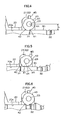
- the large-diameter portion 42 projects inward from the inner circumferential surface 20a of the ring body 20. That is, the radius of the large-diameter portion 42 is designed to be larger than the distance h from the center of rotation of the anti-disengagement member 40 to the inner circumferential surface 20a of the ring body 20.
- the front end 31 of the lens barrel 30 abuts the abutting surface 41 and the front end 31 of the lens barrel 30 moves relative to the abutting surface 41.
- the small-diameter portion 43 is situated outside the inner circumferential surface 20a of the ring body 20 and hence does not project inward from the inner circumferential surface 20a of the ring body 20. That is, the radius of the small-diameter portion 43 is designed to be smaller than (or equal to) the distance h from the center of rotation of the anti-disengagement member 40 to the inner circumferential surface 20a of the ring body 20.
- the urging force of the resilient member rotates the anti-disengagement member 40 counterclockwise in Fig. 5 and the stopper 45 abuts the one end 21 and the other end 22 (or may abut one of the one end 21 and the other end 22), so that the rotation of the anti-disengagement member 40 is restricted.
- the large-diameter portion 42 (and the abutting surface 41) projects inward from the inner circumferential surface 20a of the ring body 20.
- the large-diameter portion 42 (and the abutting surface 41) is situated in the groove 32 formed in the lens barrel 30 and the large-diameter portion 42 engages the groove 32. It is therefore possible to prevent the disengagement of the optical option attachment ring 10 until the fastening screw 23 is tightened.
- the optical option attachment ring 10 can be removed. That is, the stopper 45 restricts the rotation of anti-disengagement member 40 and also serves as a disengagement manipulation member for removing the attachment ring 10 from the lens barrel 30.
- the optical option attachment ring 10 of this embodiment after the lens barrel 30 is inserted into the ring body 20 and moved to the predetermined position (intended mounting position), the urging force of the resilient member rotates the anti-disengagement member 40 clockwise, so that the large-diameter portion 42 (and the abutting surface 41) will be situated in the groove 32 formed in the lens barrel 30. That is, the large-diameter portion 42 engages the groove 32. It is therefore possible to prevent the disengagement of the optical option attachment ring 10 until the fastening screw 23 is tightened.
- the present invention is not limited thereto.
- the small-diameter portion 43 may be of any shape as far as it will not project inward from the inner circumferential surface 20a of the ring body 20 when the anti-disengagement member 40 is rotated, as shown in Fig. 5.
- the small-diameter portion 43 may be replaced with a rectangular member.
Landscapes
- Physics & Mathematics (AREA)
- General Physics & Mathematics (AREA)
- Optics & Photonics (AREA)
- Lens Barrels (AREA)
- Accessories Of Cameras (AREA)
- Structure And Mechanism Of Cameras (AREA)
- Led Device Packages (AREA)
- Gyroscopes (AREA)
- Wire Bonding (AREA)
Abstract
Description
- The present invention relates to an optical option attachment ring, and particularly to an optical option attachment ring that will not disengage until and after a fastening screw is tightened.
- There has been conventionally known an optical option attachment ring for mounting a wide-converter, a tele-converter or the like to a lens barrel (see
Japanese Patent Application Laid-Open No. 2004-271892 - The optical option attachment ring described in
Japanese Patent Application Laid-Open No. 2004-271892 screw holes 21a' and 22a' that pass through the one end 21' and the other end 22'. The optical option attachment ring is configured such that tightening the fastening screw 23' brings the one end 21' and the other end 22' closer to each other and hence the diameter of the ring body 20' decreases so that the optical option attachment ring 10' is fastened to the lens barrel, while loosing fastening screw 23' separates the one end 21' and the other end 22' from each other and hence the diameter of the ring body 20' increases so that the optical option attachment ring 10' disengages from the lens barrel. - As shown in Fig. 9, the one end 21' and the other end 22' of the optical option attachment ring 10' have inclined portions, and tightening the fastening screw 23' moves a
part 22b' of the other end 22' along the inclined surface of the one end 21', so that thepart 22b' projects inward from the innercircumferential surface 20a' of the ring body 20' and is situated (engaged) in a groove (now shown) formed in the lens barrel. This prevents the optical option attachment ring 10' from disengaging from the lens barrel even if the fastening screw 23' loosens. - However, in the optical option attachment ring 10' described in
Japanese Patent Application Laid-Open No. 2004-271892 - The present invention has been made in view of such circumstances and aims to prevent disengagement of the optical option attachment ring until and after the fastening screw is tightened.
- The present invention has been made to solve the above problem. A first aspect of the present invention is an optical option attachment ring including one end and the other end disposed with a predetermined gap therebetween, a ring body that connects the one end to the other end and receives a lens barrel, and a fastening screw that is inserted into screw holes that pass through the one end and the other end. The optical option attachment ring is configured such that tightening the fastening screw brings the one end and the other end closer to each other and hence the diameter of the ring body decreases so that the optical option attachment ring is fastened to the lens barrel, while loosening the fastening screw separates the one end and the other end from each other and hence the diameter of the ring body increases so that the optical option attachment ring disengages from the lens barrel. The optical option attachment ring further includes a rotator having an abutting surface that projects inward from the inner circumferential surface of the ring body and abuts the front end of the lens barrel as well as an arcuate portion that follows the upper end of the abutting surface. When the lens barrel is inserted into the ring body and moved to a predetermined position, the front end of the lens barrel abuts the abutting surface and the front end of the lens barrel moves relative to the abutting surface so as to rotate the rotator, so that the abutting surface and the arcuate portion are situated outside the inner circumferential surface of the ring body. The optical option attachment ring further includes a resilient member that applies an urging force to the rotator such that the rotator rotates in the direction opposite to the above-mentioned rotation direction, and a stopper that abuts at least one of the one end and the other end so as to restrict the rotation caused by the urging force of the resilient member. When the lens barrel is inserted into the ring body and moved to the predetermined position, the urging force of the resilient member rotates the rotator so that the abutting surface and the arcuate portion are situated in a groove formed in the lens barrel.
- According to the first aspect, when the lens barrel is inserted into the ring body and moved to the predetermined position (intended mounting position), the urging force of the resilient member counter-rotates the rotator so that the abutting surface and the arcuate portion will be situated in the groove formed in the lens barrel. That is, the arcuate portion engages the groove. It is therefore possible to prevent the disengagement of the optical option attachment ring until and after the fastening screw is tightened.
- A second aspect of the present invention is the optical option attachment ring according to the first aspect configured such that the rotator is provided with an opening into which the fastening screw is inserted, and the rotator is disposed between the one end and the other end and rotatably held around the inserted fastening screw.
- According to the second aspect, since the fastening screw also serves as the axis of rotation of the rotator, there is no need to separately provide an axis of rotation of the rotator.
- A third aspect of the present invention is the optical option attachment ring according to the first or second aspect configured such that the rotator has a small arcuate portion that follows the lower end of the abutting surface and is smaller than the arcuate portion.
- According to the third aspect, it is relatively easily possible to configure the rotator.
- According to the present invention, it is possible to prevent the disengagement of the optical option attachment ring until and after the fastening screw is tightened.
-
- Fig. 1 is a view for explaining the configuration of the optical option attachment ring according to the present invention;
- Fig. 2 is a view for explaining the configuration of the optical option attachment ring according to the present invention;
- Fig. 3 is a view for explaining the configuration of an anti-disengagement member;
- Fig. 4 is a view for explaining the configuration of the anti-disengagement member;
- Fig. 5 is a view for explaining the configuration of the anti-disengagement member;
- Fig. 6 is a view for explaining the configuration of the anti-disengagement member;
- Fig. 7 is a view for explaining the configuration of the anti-disengagement member;
- Fig. 8 is a view for explaining an example of variation of the anti-disengagement member; and
- Fig. 9 is a view for explaining the configuration of a conventional optical option attachment ring.
- A preferred embodiment of the optical option attachment ring according to the present invention will be described below with reference to the accompanying drawings.
- Figs. 1 and 2 explain the configuration of the optical option attachment ring according to the present invention.
- As shown in Fig. 1, an optical
option attachment ring 10 is a structure for mount an optical option OP, such as a wide-converter and a tele-converter, to alens barrel 30. As shown in Fig. 2, the opticaloption attachment ring 10 includes oneend 21 and theother end 22 disposed with a predetermined gap therebetween and aring body 20 that connects the oneend 21 to theother end 22. - The inner diameter of the
ring body 20 is designed to be slightly larger than the outer diameter of (the front end of) thelens barrel 30, so that thelens barrel 30 can be inserted into thering body 20 and moved to a predetermined position (intended mounting position). - As shown in Fig. 2, the one
end 21 and theother end 22 are provided withscrew holes end 21 and theother end 22. Afastening screw 23 is inserted into thescrew holes - The
screw hole 21a in the oneend 21 includes a large-diameter hole 21a1, a step 21a2 that follows the large-diameter hole 21a1 and a small-diameter hole 21a3 that follows the step 21a2. When the fasteningscrew 23 is inserted into thescrew hole 21a, ascrew body 23a of the fasteningscrew 23 is situated in the large-diameter hole 21a1, and a threadedportion 23b formed on one end of thescrew body 23a is situated in the small-diameter hole 21a3. Astep 23c is formed at the boundary between thescrew body 23a and the threadedportion 23b. When thefastening screw 23 is inserted into thescrew hole 21a, thestep 23c abuts the step 21a2 of thescrew hole 21a, so that thestep 23c prevents thefastening screw 23 from being inserted any further. On the other hand, a thread groove in which the threadedportion 23b of the fasteningscrew 23 is screwed is formed in a threadedhole 22a in theother end 22. - Therefore, when a
knob 23d of the fasteningscrew 23 is rotated in the direction in which the fasteningscrew 23 is tightened, the oneend 21 and theother end 22 are brought relatively closer to each other, so that the diameter of thering body 20 decreases. Thus, the opticaloption attachment ring 10 is fastened to thelens barrel 30. - On the other hand, when the
knob 23d of the fasteningscrew 23 is rotated in the direction in which thefastening screw 23 is loosened, the oneend 21 and theother end 22 are relatively separated from each other, so that the diameter of thering body 20 increases. Thus, the diameter of the opticaloption attachment ring 10 returns to its initial value. That is, the opticaloption attachment ring 10 is unfastened from thelens barrel 30. - A configuration for preventing the thus configured optical
option attachment ring 10 from disengaging from the lens barrel will now be described. - To prevent the disengagement, the optical
option attachment ring 10 includes an anti-disengagement member 40 (corresponding to a rotator of the present invention). - The
anti-disengagement member 40 can be made of, for example, polyacetal resin (POM), Teflon® or other synthetic resins. - As shown in Fig. 1, the
anti-disengagement member 40 is a plate-like member and includes anabutting surface 41 that abuts thefront end 31 of thelens barrel 30 when thelens barrel 30 is inserted. A large-diameter portion 42 (corresponding to an arcuate portion of the present invention) is provided such that it follows the upper end of theabutting surface 41, while a small-diameter portion 43 is provided such that it follows the lower end of theabutting surface 41. - As shown in Fig. 3, the
anti-disengagement member 40 is disposed between the oneend 21 and theother end 22, and thefastening screw 23 is inserted into anopening 44 formed at the center of theanti-disengagement member 40 to rotatably hold theanti-disengagement member 40 around the fasteningscrew 23. Since thefastening screw 23 also serves as the axis of rotation of theanti-disengagement member 40, there is no need to separately provide an axis of rotation of theanti-disengagement member 40. - The
anti-disengagement member 40 is connected to theother end 22 via a resilient member B (for example, part of a coil spring). The resilient member B is a member for applying an urging force to theanti-disengagement member 40 such that theanti-disengagement member 40 is rotated counterclockwise in Fig. 1. However, theanti-disengagement member 40 is provided with astopper 45, and thestopper 45 abuts the oneend 21 and theother end 22, restricting the rotation of theanti-disengagement member 40 caused by the resilient member B. As shown in Fig. 4, when thestopper 45 abuts the oneend 21 and theother end 22, the large-diameter portion 42 (and the abutting surface 41) projects inward from the innercircumferential surface 20a of thering body 20. That is, the radius of the large-diameter portion 42 is designed to be larger than the distance h from the center of rotation of theanti-disengagement member 40 to the innercircumferential surface 20a of thering body 20. - On the other hand, when the
lens barrel 30 is inserted into thering body 20 and moved to the predetermined position (intended mounting position), thefront end 31 of thelens barrel 30 abuts the abuttingsurface 41 and thefront end 31 of thelens barrel 30 moves relative to the abuttingsurface 41. This rotates theanti-disengagement member 40 clockwise in Fig. 4, so that the large-diameter portion 42 (and the abutting surface 41) is situated outside the innercircumferential surface 20a of thering body 20, as shown in Fig. 5. At this point, the small-diameter portion 43 is situated outside the innercircumferential surface 20a of thering body 20 and hence does not project inward from the innercircumferential surface 20a of thering body 20. That is, the radius of the small-diameter portion 43 is designed to be smaller than (or equal to) the distance h from the center of rotation of theanti-disengagement member 40 to the innercircumferential surface 20a of thering body 20. - Then, when the
ring body 20 is moved to the predetermined position (intended mounting position) (that is, when the abuttingsurface 41 reaches agroove 32 of the lens barrel), the urging force of the resilient member rotates theanti-disengagement member 40 counterclockwise in Fig. 5 and thestopper 45 abuts the oneend 21 and the other end 22 (or may abut one of the oneend 21 and the other end 22), so that the rotation of theanti-disengagement member 40 is restricted. Thus, as shown in Fig. 6, the large-diameter portion 42 (and the abutting surface 41) projects inward from the innercircumferential surface 20a of thering body 20. That is, the large-diameter portion 42 (and the abutting surface 41) is situated in thegroove 32 formed in thelens barrel 30 and the large-diameter portion 42 engages thegroove 32. It is therefore possible to prevent the disengagement of the opticaloption attachment ring 10 until thefastening screw 23 is tightened. - By grabbing and manipulating the
stopper 45 by a finger to rotate theanti-disengagement member 40 clockwise in Fig. 6 so as to allow the large-diameter portion 42 (and the abutting surface 41) to be situated outside the innercircumferential surface 20a of thering body 20 as shown in Fig. 7, the opticaloption attachment ring 10 can be removed. That is, thestopper 45 restricts the rotation ofanti-disengagement member 40 and also serves as a disengagement manipulation member for removing theattachment ring 10 from thelens barrel 30. - As described above, according to the optical
option attachment ring 10 of this embodiment, after thelens barrel 30 is inserted into thering body 20 and moved to the predetermined position (intended mounting position), the urging force of the resilient member rotates theanti-disengagement member 40 clockwise, so that the large-diameter portion 42 (and the abutting surface 41) will be situated in thegroove 32 formed in thelens barrel 30. That is, the large-diameter portion 42 engages thegroove 32. It is therefore possible to prevent the disengagement of the opticaloption attachment ring 10 until thefastening screw 23 is tightened. - In the above embodiment, although the description has been made of the case where the
anti-disengagement member 40 has the large-diameter portion 42 and the small-diameter portion 43, the present invention is not limited thereto. The small-diameter portion 43 may be of any shape as far as it will not project inward from the innercircumferential surface 20a of thering body 20 when theanti-disengagement member 40 is rotated, as shown in Fig. 5. For example, as shown in Fig. 8, the small-diameter portion 43 may be replaced with a rectangular member. - The above embodiment is presented only by way of example in all respect. The present invention should not be construed in a limiting sense by the above description. The present invention can be implemented in various other forms without departing from the spirit and major features thereof.
Claims (3)
- An optical option attachment ring (10) including: a ring body (20) that connects one end (21) to the other end (22), receives a lens barrel (30), and has a predetermined gap between the one end (21) and the other end (22); a fastening screw (23) that is inserted into screw holes (21a), (22a) that pass through the one end (21) and the other end (22); the one end (21) and the other end (22), the ring body (20) and the fastening screw (23) configured such that tightening the fastening screw (23) brings the one end (21) and the other end (22) closer to each other and hence the diameter of the ring body (20) decreases so that the optical option attachment ring (10) is fastened to the lens barrel (30), while loosening the fastening screw (23) separates the one end (21) and the other end (22) from each other and hence the diameter of the ring body (20) increases so that the optical option attachment ring (10) disengages from the lens barrel (30), characterized by comprising:a rotator (40) having an abutting surface (41) that projects inward from the inner circumferential surface (20a) of the ring body (20) and abuts the front end (31) of the lens barrel (30) as well as an arcuate portion (42) that follows the upper end of the abutting surface (41);a resilient member (B) that applies an urging force to the rotator (40) such that the rotator (40) rotates in the direction opposite to the above-mentioned rotation direction; anda stopper (45) that abuts at least one of the one end (21) and the other end (22) so as to restrict the rotation caused by urging force of the resilient member (B),characterized in that
the rotator (40) is configured such that when the lens barrel (30) is inserted into the ring body (20) and moved to a predetermined position, the front end (31) of the lens barrel (30) abuts the abutting surface (41) and the front end (31) of the lens barrel (30) moves relative to the abutting surface (41) so as to rotate the rotator (40), so that the abutting surface (41) and the arcuate portion (42) are situated outside the inner circumferential surface (20a) of the ring body (20),
when the lens barrel (30) is inserted into the ring body (20) and moved to the predetermined position, the urging force of the resilient member (B) rotates the rotator (40) so that the abutting surface (41) and the arcuate portion (42) are situated in a groove (32) formed in the lens barrel (30). - The optical option attachment ring (10) according to claim 1, characterized in that
the rotator (40) is provided with an opening into which the fastening screw (23) is inserted, and the rotator (40) is disposed between the one end (21) and the other end (22), and rotatably held around the inserted fastening screw (23). - The optical option attachment ring (10) according to claim 1 or 2, characterized in that
the rotator (40) has a small arcuate portion (42) that follows the lower end of the abutting surface (41) and is smaller than the arcuate portion (42).
Applications Claiming Priority (1)
| Application Number | Priority Date | Filing Date | Title |
|---|---|---|---|
| JP2006099995A JP4687899B2 (en) | 2006-03-31 | 2006-03-31 | Optical option mounting ring |
Publications (2)
| Publication Number | Publication Date |
|---|---|
| EP1840613A1 true EP1840613A1 (en) | 2007-10-03 |
| EP1840613B1 EP1840613B1 (en) | 2008-07-09 |
Family
ID=38137488
Family Applications (1)
| Application Number | Title | Priority Date | Filing Date |
|---|---|---|---|
| EP07006264A Active EP1840613B1 (en) | 2006-03-31 | 2007-03-27 | Optical option attachment ring |
Country Status (5)
| Country | Link |
|---|---|
| US (1) | US7693417B2 (en) |
| EP (1) | EP1840613B1 (en) |
| JP (1) | JP4687899B2 (en) |
| AT (1) | ATE400830T1 (en) |
| DE (1) | DE602007000033D1 (en) |
Families Citing this family (1)
| Publication number | Priority date | Publication date | Assignee | Title |
|---|---|---|---|---|
| JP5761957B2 (en) * | 2010-10-21 | 2015-08-12 | キヤノン株式会社 | Adapter for optical accessories |
Citations (5)
| Publication number | Priority date | Publication date | Assignee | Title |
|---|---|---|---|---|
| JPH10186202A (en) * | 1996-12-24 | 1998-07-14 | Sony Corp | Lens adapter mounting device |
| JP2004109717A (en) * | 2002-09-20 | 2004-04-08 | Marumi Koki Kk | Attachment and detachment mechanism for lens attachment of camera |
| JP2004271892A (en) * | 2003-03-07 | 2004-09-30 | Canon Inc | Optical accessories barrel |
| JP2005017375A (en) * | 2003-06-23 | 2005-01-20 | Olympus Corp | Lens barrel holder and lens barrel holder-attachable/detachable lens barrel |
| US20050237635A1 (en) * | 2004-01-28 | 2005-10-27 | Jun Sugita | Lens barrel holding apparatus, lens barrel and camera system |
Family Cites Families (10)
| Publication number | Priority date | Publication date | Assignee | Title |
|---|---|---|---|---|
| US3987680A (en) * | 1973-08-27 | 1976-10-26 | Mitsumi Electric Co., Ltd. | Uhf tuner device |
| JPS579913U (en) * | 1980-06-18 | 1982-01-19 | ||
| JPH0711661B2 (en) * | 1986-04-21 | 1995-02-08 | 京セラ株式会社 | Detachable mounting device for cylindrical body |
| JPH04130912U (en) * | 1991-05-21 | 1992-12-01 | 旭光学工業株式会社 | Lens barrel tripod mount |
| US5647743A (en) * | 1993-05-11 | 1997-07-15 | Schmitt; Friedrich | Device for treating jaw fractures or tooth displacements |
| JP3867389B2 (en) * | 1998-03-05 | 2007-01-10 | フジノン株式会社 | Camera extender device |
| JP2001305617A (en) * | 2000-04-19 | 2001-11-02 | Canon Inc | Flash light emitting device |
| JP4277422B2 (en) * | 2000-05-19 | 2009-06-10 | フジノン株式会社 | Optical device |
| US6568644B2 (en) * | 2001-05-25 | 2003-05-27 | Jac Products Inc. | Clamp for a cross bar |
| US7533910B2 (en) * | 2006-02-01 | 2009-05-19 | R.G. Ray Corp. | Clamp |
-
2006
- 2006-03-31 JP JP2006099995A patent/JP4687899B2/en not_active Expired - Fee Related
-
2007
- 2007-03-27 AT AT07006264T patent/ATE400830T1/en not_active IP Right Cessation
- 2007-03-27 DE DE602007000033T patent/DE602007000033D1/en active Active
- 2007-03-27 EP EP07006264A patent/EP1840613B1/en active Active
- 2007-03-29 US US11/730,048 patent/US7693417B2/en not_active Expired - Fee Related
Patent Citations (5)
| Publication number | Priority date | Publication date | Assignee | Title |
|---|---|---|---|---|
| JPH10186202A (en) * | 1996-12-24 | 1998-07-14 | Sony Corp | Lens adapter mounting device |
| JP2004109717A (en) * | 2002-09-20 | 2004-04-08 | Marumi Koki Kk | Attachment and detachment mechanism for lens attachment of camera |
| JP2004271892A (en) * | 2003-03-07 | 2004-09-30 | Canon Inc | Optical accessories barrel |
| JP2005017375A (en) * | 2003-06-23 | 2005-01-20 | Olympus Corp | Lens barrel holder and lens barrel holder-attachable/detachable lens barrel |
| US20050237635A1 (en) * | 2004-01-28 | 2005-10-27 | Jun Sugita | Lens barrel holding apparatus, lens barrel and camera system |
Also Published As
| Publication number | Publication date |
|---|---|
| DE602007000033D1 (en) | 2008-08-21 |
| JP4687899B2 (en) | 2011-05-25 |
| US7693417B2 (en) | 2010-04-06 |
| EP1840613B1 (en) | 2008-07-09 |
| JP2007272093A (en) | 2007-10-18 |
| ATE400830T1 (en) | 2008-07-15 |
| US20070230951A1 (en) | 2007-10-04 |
Similar Documents
| Publication | Publication Date | Title |
|---|---|---|
| JP5443708B2 (en) | Fastening device with tolerance adjustment function | |
| US10179548B2 (en) | Closure device for fastening an object to a carrier element and fastener for fastening an object to a carrier element | |
| US6183293B1 (en) | Electrical connector latching mechanism | |
| JP4514067B2 (en) | Locking nut | |
| US6486843B2 (en) | On-vehicle rod antenna device | |
| JP2008304063A5 (en) | ||
| US20020076269A1 (en) | Device for connecting structural components | |
| US20020133908A1 (en) | Positioning hinge adapted between a computer main body and a display | |
| US20070128003A1 (en) | Combination of a nut and a washer | |
| EP1850163B1 (en) | Optical option attachment ring | |
| US20130108393A1 (en) | Screw assembly | |
| CN1669375A (en) | Especially for measuring torsionally fixed parts of transmitter housings | |
| EP1840613B1 (en) | Optical option attachment ring | |
| US20200133104A1 (en) | Hinged filter attachment for a photographic lens | |
| US20090001735A1 (en) | Mechanism for Securing the Handle of a Door or Window | |
| US6485141B2 (en) | Lens-installing apparatus for rimless eyeglasses | |
| JP2018163210A (en) | Electronic equipment | |
| CN100466887C (en) | appliance panel | |
| JP2007227584A (en) | tightening structure | |
| US20140301731A1 (en) | Rotation mechanism for camera | |
| JP4206935B2 (en) | Telescope adapter for digital camera | |
| JP2019190578A (en) | Screw drop-off prevention mechanism | |
| KR102340362B1 (en) | Tilt fixing apparatus of steering column for vehicle | |
| JP4088208B2 (en) | Rotation angle detector | |
| US10046623B2 (en) | Fitting assembly |
Legal Events
| Date | Code | Title | Description |
|---|---|---|---|
| PUAI | Public reference made under article 153(3) epc to a published international application that has entered the european phase |
Free format text: ORIGINAL CODE: 0009012 |
|
| 17P | Request for examination filed |
Effective date: 20070327 |
|
| AK | Designated contracting states |
Kind code of ref document: A1 Designated state(s): AT BE BG CH CY CZ DE DK EE ES FI FR GB GR HU IE IS IT LI LT LU LV MC MT NL PL PT RO SE SI SK TR |
|
| AX | Request for extension of the european patent |
Extension state: AL BA HR MK YU |
|
| GRAP | Despatch of communication of intention to grant a patent |
Free format text: ORIGINAL CODE: EPIDOSNIGR1 |
|
| GRAS | Grant fee paid |
Free format text: ORIGINAL CODE: EPIDOSNIGR3 |
|
| GRAA | (expected) grant |
Free format text: ORIGINAL CODE: 0009210 |
|
| AKX | Designation fees paid |
Designated state(s): AT BE BG CH CY CZ DE DK EE ES FI FR GB GR HU IE IS IT LI LT LU LV MC MT NL PL PT RO SE SI SK TR |
|
| AK | Designated contracting states |
Kind code of ref document: B1 Designated state(s): AT BE BG CH CY CZ DE DK EE ES FI FR GB GR HU IE IS IT LI LT LU LV MC MT NL PL PT RO SE SI SK TR |
|
| REG | Reference to a national code |
Ref country code: GB Ref legal event code: FG4D |
|
| REG | Reference to a national code |
Ref country code: CH Ref legal event code: EP |
|
| REF | Corresponds to: |
Ref document number: 602007000033 Country of ref document: DE Date of ref document: 20080821 Kind code of ref document: P |
|
| REG | Reference to a national code |
Ref country code: IE Ref legal event code: FG4D |
|
| NLV1 | Nl: lapsed or annulled due to failure to fulfill the requirements of art. 29p and 29m of the patents act | ||
| PG25 | Lapsed in a contracting state [announced via postgrant information from national office to epo] |
Ref country code: IS Free format text: LAPSE BECAUSE OF FAILURE TO SUBMIT A TRANSLATION OF THE DESCRIPTION OR TO PAY THE FEE WITHIN THE PRESCRIBED TIME-LIMIT Effective date: 20081109 Ref country code: NL Free format text: LAPSE BECAUSE OF FAILURE TO SUBMIT A TRANSLATION OF THE DESCRIPTION OR TO PAY THE FEE WITHIN THE PRESCRIBED TIME-LIMIT Effective date: 20080709 Ref country code: LT Free format text: LAPSE BECAUSE OF FAILURE TO SUBMIT A TRANSLATION OF THE DESCRIPTION OR TO PAY THE FEE WITHIN THE PRESCRIBED TIME-LIMIT Effective date: 20080709 |
|
| PG25 | Lapsed in a contracting state [announced via postgrant information from national office to epo] |
Ref country code: LV Free format text: LAPSE BECAUSE OF FAILURE TO SUBMIT A TRANSLATION OF THE DESCRIPTION OR TO PAY THE FEE WITHIN THE PRESCRIBED TIME-LIMIT Effective date: 20080709 Ref country code: PT Free format text: LAPSE BECAUSE OF FAILURE TO SUBMIT A TRANSLATION OF THE DESCRIPTION OR TO PAY THE FEE WITHIN THE PRESCRIBED TIME-LIMIT Effective date: 20081209 Ref country code: ES Free format text: LAPSE BECAUSE OF FAILURE TO SUBMIT A TRANSLATION OF THE DESCRIPTION OR TO PAY THE FEE WITHIN THE PRESCRIBED TIME-LIMIT Effective date: 20081020 Ref country code: SI Free format text: LAPSE BECAUSE OF FAILURE TO SUBMIT A TRANSLATION OF THE DESCRIPTION OR TO PAY THE FEE WITHIN THE PRESCRIBED TIME-LIMIT Effective date: 20080709 Ref country code: BG Free format text: LAPSE BECAUSE OF FAILURE TO SUBMIT A TRANSLATION OF THE DESCRIPTION OR TO PAY THE FEE WITHIN THE PRESCRIBED TIME-LIMIT Effective date: 20081009 Ref country code: AT Free format text: LAPSE BECAUSE OF FAILURE TO SUBMIT A TRANSLATION OF THE DESCRIPTION OR TO PAY THE FEE WITHIN THE PRESCRIBED TIME-LIMIT Effective date: 20080709 Ref country code: FI Free format text: LAPSE BECAUSE OF FAILURE TO SUBMIT A TRANSLATION OF THE DESCRIPTION OR TO PAY THE FEE WITHIN THE PRESCRIBED TIME-LIMIT Effective date: 20080709 |
|
| PG25 | Lapsed in a contracting state [announced via postgrant information from national office to epo] |
Ref country code: BE Free format text: LAPSE BECAUSE OF FAILURE TO SUBMIT A TRANSLATION OF THE DESCRIPTION OR TO PAY THE FEE WITHIN THE PRESCRIBED TIME-LIMIT Effective date: 20080709 |
|
| PG25 | Lapsed in a contracting state [announced via postgrant information from national office to epo] |
Ref country code: EE Free format text: LAPSE BECAUSE OF FAILURE TO SUBMIT A TRANSLATION OF THE DESCRIPTION OR TO PAY THE FEE WITHIN THE PRESCRIBED TIME-LIMIT Effective date: 20080709 Ref country code: DK Free format text: LAPSE BECAUSE OF FAILURE TO SUBMIT A TRANSLATION OF THE DESCRIPTION OR TO PAY THE FEE WITHIN THE PRESCRIBED TIME-LIMIT Effective date: 20080709 |
|
| PLBE | No opposition filed within time limit |
Free format text: ORIGINAL CODE: 0009261 |
|
| STAA | Information on the status of an ep patent application or granted ep patent |
Free format text: STATUS: NO OPPOSITION FILED WITHIN TIME LIMIT |
|
| PG25 | Lapsed in a contracting state [announced via postgrant information from national office to epo] |
Ref country code: RO Free format text: LAPSE BECAUSE OF FAILURE TO SUBMIT A TRANSLATION OF THE DESCRIPTION OR TO PAY THE FEE WITHIN THE PRESCRIBED TIME-LIMIT Effective date: 20080709 Ref country code: SK Free format text: LAPSE BECAUSE OF FAILURE TO SUBMIT A TRANSLATION OF THE DESCRIPTION OR TO PAY THE FEE WITHIN THE PRESCRIBED TIME-LIMIT Effective date: 20080709 Ref country code: CZ Free format text: LAPSE BECAUSE OF FAILURE TO SUBMIT A TRANSLATION OF THE DESCRIPTION OR TO PAY THE FEE WITHIN THE PRESCRIBED TIME-LIMIT Effective date: 20080709 |
|
| 26N | No opposition filed |
Effective date: 20090414 |
|
| PG25 | Lapsed in a contracting state [announced via postgrant information from national office to epo] |
Ref country code: IT Free format text: LAPSE BECAUSE OF FAILURE TO SUBMIT A TRANSLATION OF THE DESCRIPTION OR TO PAY THE FEE WITHIN THE PRESCRIBED TIME-LIMIT Effective date: 20080709 |
|
| PG25 | Lapsed in a contracting state [announced via postgrant information from national office to epo] |
Ref country code: MC Free format text: LAPSE BECAUSE OF NON-PAYMENT OF DUE FEES Effective date: 20090331 |
|
| REG | Reference to a national code |
Ref country code: IE Ref legal event code: MM4A |
|
| PG25 | Lapsed in a contracting state [announced via postgrant information from national office to epo] |
Ref country code: SE Free format text: LAPSE BECAUSE OF FAILURE TO SUBMIT A TRANSLATION OF THE DESCRIPTION OR TO PAY THE FEE WITHIN THE PRESCRIBED TIME-LIMIT Effective date: 20081009 Ref country code: IE Free format text: LAPSE BECAUSE OF NON-PAYMENT OF DUE FEES Effective date: 20090327 |
|
| PG25 | Lapsed in a contracting state [announced via postgrant information from national office to epo] |
Ref country code: PL Free format text: LAPSE BECAUSE OF FAILURE TO SUBMIT A TRANSLATION OF THE DESCRIPTION OR TO PAY THE FEE WITHIN THE PRESCRIBED TIME-LIMIT Effective date: 20080709 |
|
| PG25 | Lapsed in a contracting state [announced via postgrant information from national office to epo] |
Ref country code: GR Free format text: LAPSE BECAUSE OF FAILURE TO SUBMIT A TRANSLATION OF THE DESCRIPTION OR TO PAY THE FEE WITHIN THE PRESCRIBED TIME-LIMIT Effective date: 20081010 |
|
| PG25 | Lapsed in a contracting state [announced via postgrant information from national office to epo] |
Ref country code: LU Free format text: LAPSE BECAUSE OF NON-PAYMENT OF DUE FEES Effective date: 20090327 |
|
| PG25 | Lapsed in a contracting state [announced via postgrant information from national office to epo] |
Ref country code: HU Free format text: LAPSE BECAUSE OF FAILURE TO SUBMIT A TRANSLATION OF THE DESCRIPTION OR TO PAY THE FEE WITHIN THE PRESCRIBED TIME-LIMIT Effective date: 20090110 |
|
| PG25 | Lapsed in a contracting state [announced via postgrant information from national office to epo] |
Ref country code: TR Free format text: LAPSE BECAUSE OF FAILURE TO SUBMIT A TRANSLATION OF THE DESCRIPTION OR TO PAY THE FEE WITHIN THE PRESCRIBED TIME-LIMIT Effective date: 20080709 |
|
| PG25 | Lapsed in a contracting state [announced via postgrant information from national office to epo] |
Ref country code: CY Free format text: LAPSE BECAUSE OF FAILURE TO SUBMIT A TRANSLATION OF THE DESCRIPTION OR TO PAY THE FEE WITHIN THE PRESCRIBED TIME-LIMIT Effective date: 20080709 |
|
| REG | Reference to a national code |
Ref country code: CH Ref legal event code: PL |
|
| PG25 | Lapsed in a contracting state [announced via postgrant information from national office to epo] |
Ref country code: LI Free format text: LAPSE BECAUSE OF NON-PAYMENT OF DUE FEES Effective date: 20110331 Ref country code: CH Free format text: LAPSE BECAUSE OF NON-PAYMENT OF DUE FEES Effective date: 20110331 |
|
| PGFP | Annual fee paid to national office [announced via postgrant information from national office to epo] |
Ref country code: GB Payment date: 20130327 Year of fee payment: 7 Ref country code: DE Payment date: 20130320 Year of fee payment: 7 Ref country code: FR Payment date: 20130325 Year of fee payment: 7 |
|
| REG | Reference to a national code |
Ref country code: DE Ref legal event code: R119 Ref document number: 602007000033 Country of ref document: DE |
|
| GBPC | Gb: european patent ceased through non-payment of renewal fee |
Effective date: 20140327 |
|
| REG | Reference to a national code |
Ref country code: FR Ref legal event code: ST Effective date: 20141128 |
|
| REG | Reference to a national code |
Ref country code: DE Ref legal event code: R119 Ref document number: 602007000033 Country of ref document: DE Effective date: 20141001 |
|
| PG25 | Lapsed in a contracting state [announced via postgrant information from national office to epo] |
Ref country code: DE Free format text: LAPSE BECAUSE OF NON-PAYMENT OF DUE FEES Effective date: 20141001 Ref country code: GB Free format text: LAPSE BECAUSE OF NON-PAYMENT OF DUE FEES Effective date: 20140327 Ref country code: FR Free format text: LAPSE BECAUSE OF NON-PAYMENT OF DUE FEES Effective date: 20140331 |