EP1840499A1 - Multi tip clearance measurement system and method of operation - Google Patents
Multi tip clearance measurement system and method of operation Download PDFInfo
- Publication number
- EP1840499A1 EP1840499A1 EP07104728A EP07104728A EP1840499A1 EP 1840499 A1 EP1840499 A1 EP 1840499A1 EP 07104728 A EP07104728 A EP 07104728A EP 07104728 A EP07104728 A EP 07104728A EP 1840499 A1 EP1840499 A1 EP 1840499A1
- Authority
- EP
- European Patent Office
- Prior art keywords
- clearance
- probe tips
- probe
- sensor
- signals
- Prior art date
- Legal status (The legal status is an assumption and is not a legal conclusion. Google has not performed a legal analysis and makes no representation as to the accuracy of the status listed.)
- Withdrawn
Links
- 238000005259 measurement Methods 0.000 title claims abstract description 43
- 238000000034 method Methods 0.000 title claims description 38
- 239000000523 sample Substances 0.000 claims abstract description 118
- 238000012545 processing Methods 0.000 claims abstract description 19
- 230000036541 health Effects 0.000 claims description 4
- 238000011088 calibration curve Methods 0.000 claims description 3
- 238000012544 monitoring process Methods 0.000 claims description 3
- 238000006073 displacement reaction Methods 0.000 description 7
- 230000000875 corresponding effect Effects 0.000 description 6
- 230000008859 change Effects 0.000 description 5
- 238000001514 detection method Methods 0.000 description 3
- PXHVJJICTQNCMI-UHFFFAOYSA-N Nickel Chemical compound [Ni] PXHVJJICTQNCMI-UHFFFAOYSA-N 0.000 description 2
- 238000011217 control strategy Methods 0.000 description 2
- 238000012937 correction Methods 0.000 description 2
- 230000007423 decrease Effects 0.000 description 2
- 238000013461 design Methods 0.000 description 2
- 239000000463 material Substances 0.000 description 2
- 238000012986 modification Methods 0.000 description 2
- 230000004048 modification Effects 0.000 description 2
- BASFCYQUMIYNBI-UHFFFAOYSA-N platinum Chemical compound [Pt] BASFCYQUMIYNBI-UHFFFAOYSA-N 0.000 description 2
- 230000008569 process Effects 0.000 description 2
- 238000000926 separation method Methods 0.000 description 2
- 238000012360 testing method Methods 0.000 description 2
- XAGFODPZIPBFFR-UHFFFAOYSA-N aluminium Chemical compound [Al] XAGFODPZIPBFFR-UHFFFAOYSA-N 0.000 description 1
- 229910052782 aluminium Inorganic materials 0.000 description 1
- 229910017052 cobalt Inorganic materials 0.000 description 1
- 239000010941 cobalt Substances 0.000 description 1
- GUTLYIVDDKVIGB-UHFFFAOYSA-N cobalt atom Chemical compound [Co] GUTLYIVDDKVIGB-UHFFFAOYSA-N 0.000 description 1
- 239000002131 composite material Substances 0.000 description 1
- 230000003750 conditioning effect Effects 0.000 description 1
- 230000001276 controlling effect Effects 0.000 description 1
- 230000002596 correlated effect Effects 0.000 description 1
- 229910003460 diamond Inorganic materials 0.000 description 1
- 239000010432 diamond Substances 0.000 description 1
- 230000000694 effects Effects 0.000 description 1
- 238000011156 evaluation Methods 0.000 description 1
- 239000012530 fluid Substances 0.000 description 1
- 229910000833 kovar Inorganic materials 0.000 description 1
- 229910052759 nickel Inorganic materials 0.000 description 1
- 230000003647 oxidation Effects 0.000 description 1
- 238000007254 oxidation reaction Methods 0.000 description 1
- 238000012856 packing Methods 0.000 description 1
- 229910052697 platinum Inorganic materials 0.000 description 1
- 229910052703 rhodium Inorganic materials 0.000 description 1
- 239000010948 rhodium Substances 0.000 description 1
- MHOVAHRLVXNVSD-UHFFFAOYSA-N rhodium atom Chemical compound [Rh] MHOVAHRLVXNVSD-UHFFFAOYSA-N 0.000 description 1
- 230000035945 sensitivity Effects 0.000 description 1
- 230000003068 static effect Effects 0.000 description 1
- 238000012546 transfer Methods 0.000 description 1
Images



Classifications
-
- G—PHYSICS
- G01—MEASURING; TESTING
- G01B—MEASURING LENGTH, THICKNESS OR SIMILAR LINEAR DIMENSIONS; MEASURING ANGLES; MEASURING AREAS; MEASURING IRREGULARITIES OF SURFACES OR CONTOURS
- G01B7/00—Measuring arrangements characterised by the use of electric or magnetic techniques
- G01B7/14—Measuring arrangements characterised by the use of electric or magnetic techniques for measuring distance or clearance between spaced objects or spaced apertures
-
- F—MECHANICAL ENGINEERING; LIGHTING; HEATING; WEAPONS; BLASTING
- F01—MACHINES OR ENGINES IN GENERAL; ENGINE PLANTS IN GENERAL; STEAM ENGINES
- F01D—NON-POSITIVE DISPLACEMENT MACHINES OR ENGINES, e.g. STEAM TURBINES
- F01D21/00—Shutting-down of machines or engines, e.g. in emergency; Regulating, controlling, or safety means not otherwise provided for
- F01D21/003—Arrangements for testing or measuring
-
- G—PHYSICS
- G01—MEASURING; TESTING
- G01B—MEASURING LENGTH, THICKNESS OR SIMILAR LINEAR DIMENSIONS; MEASURING ANGLES; MEASURING AREAS; MEASURING IRREGULARITIES OF SURFACES OR CONTOURS
- G01B21/00—Measuring arrangements or details thereof, where the measuring technique is not covered by the other groups of this subclass, unspecified or not relevant
- G01B21/16—Measuring arrangements or details thereof, where the measuring technique is not covered by the other groups of this subclass, unspecified or not relevant for measuring distance of clearance between spaced objects
-
- F—MECHANICAL ENGINEERING; LIGHTING; HEATING; WEAPONS; BLASTING
- F05—INDEXING SCHEMES RELATING TO ENGINES OR PUMPS IN VARIOUS SUBCLASSES OF CLASSES F01-F04
- F05D—INDEXING SCHEME FOR ASPECTS RELATING TO NON-POSITIVE-DISPLACEMENT MACHINES OR ENGINES, GAS-TURBINES OR JET-PROPULSION PLANTS
- F05D2260/00—Function
- F05D2260/80—Diagnostics
Definitions
- the invention relates generally to clearance measurement systems, and more particularly to, a multi tip clearance measurement system for measuring a clearance between a stationary component and a movable component of a rotating machine.
- a steam turbine has a rotating bucket that is disposed adjacent a carrier.
- the clearance between the rotating bucket and the carrier varies due to various operating conditions, such as changes in temperature, oxidation of the bucket tip, and so forth. It is desirable that a gap or clearance between the rotating bucket and the carrier be maintained during operation of the steam turbine.
- One existing sensor is a multi tip capacitance sensor that includes multiple probe tips to measure capacitance for estimating the radial and axial clearance between stationary and movable components.
- the estimated clearance is a function of gain of all the signals from all the probe tips of the sensor.
- an error in this gain, or a drift over a period time causes the system performance to deteriorate.
- certain systems employ signal processing to evaluate the health of the individual signals from the probe tips and transfer functions are used to convert the measured signal to clearance. Again, error correction of individual gain of the probe tips is not addressed in such systems.
- clearance measurement systems are typically employed to measure clearances between components during design and offline testing.
- these existing systems are ineffective for in-service measurements due to the noise and drift generated by changes in the geometry of the components, among other factors.
- in-service clearance control is based on the clearance measurements previously taken during design and offline testing of components. As the components become worn during service, the offline measurements become ineffective for in-service clearance control.
- a multi tip clearance measurement system includes a sensor disposed on a first object, wherein the sensor comprises a plurality of probe tips configured to generate signals representative of a sensed parameter corresponding to a second object and a processing unit configured to evaluate the signals from subsets of the sensed parameters from the probe tips to detect an outlier probe tip and to adjust a gain, or an offset of the respective outlier probe tip for estimating the clearance between the first and second objects based upon the signals.
- a method of measuring clearance between first and second objects includes receiving a plurality of signals representative of a sensed parameter corresponding to the first or second object via a sensor having a plurality of probe tips and estimating the clearance between the first and second objects based upon simultaneous subsets of the sensed parameters from the probe tips.
- the method also includes analyzing the estimated clearance from the subsets of sensed parameters from the probe tips to detect an outlier probe tip and adjusting a gain, or an offset of the outlier probe tip to estimate the clearance based upon the plurality of signals.
- a method of measuring clearance between first and second objects includes receiving a plurality of signals representative of a sensed parameter corresponding to the first or second object via a sensor having a plurality of probe tips and estimating the clearance between the first and second objects based upon simultaneous subsets of the sensed parameters from the probe tips.
- the method also includes analyzing the estimated clearance from the subsets of sensed parameters from the probe tips to detect an outlier probe tip and estimating the clearance based upon the signals from the probe tips other than the outlier probe tip.
- a rotating machine in another embodiment, includes a rotating component spaced apart from a stationary component and a sensor disposed on the stationary component, wherein the sensor comprises a plurality of probe tips configured to generate signals representative of a sensed parameter corresponding to the rotating component.
- the rotating machine also includes a processing unit configured to evaluate the signals from subsets of the sensed parameters from the probe tips to detect an outlier probe tip and to adjust a gain, or an offset of the respective outlier probe tip for estimating the clearance between the stationary and rotating components based upon the signals.
- a method of monitoring health of a multi tip clearance measurement system includes receiving a plurality of signals representative of a sensed parameter corresponding to a first or a second object via a sensor having a plurality of probe tips and storing the plurality of signals received from the plurality of probe tips.
- the method also includes estimating the clearance between the first and second objects based upon simultaneous subsets of sensed parameters from the probe tips and analyzing the estimated clearance from the subsets of the sensed parameters from the probe tips to detect an outlier probe tip.
- FIG. 1 illustrates a steam turbine 10 having a multi tip clearance measurement system 12 for measuring a clearance between two objects in the steam turbine 10.
- the clearance measurement system 12 includes a sensor having a plurality of probe tips that is configured for measuring the clearance between a rotating component 14 and a stationary component 16 in the steam turbine 10, which will be described in detail below.
- FIG. 2 illustrates a rotating machine, such as a steam turbine 20 as illustrated in FIG. 1, wherein aspects of the present technique can be incorporated to measure clearance between rotating and stationary components.
- the steam turbine 20 includes a rotor 22 disposed within a stationary housing 24.
- a plurality of turbine blades 26, which may also be referred to as buckets, are affixed to the rotor 22.
- the blades 26 are subjected to steam at a high temperature and pressure, which causes the blades 26 to rotate about an axis.
- the blades 26 rotate within the stationary housing or shroud 24 that is positioned radially and circumferentially around the blades 26.
- one or more clearance sensors such as represented by reference numerals 28, 30 and 32 are disposed circumferentially around the stationary shroud 24.
- each of the clearance sensors 28, 30 and 32 includes a plurality of probe tips configured to generate signals representative of a sensed parameter corresponding to the blades 26.
- the clearance between the blades 26 and the shroud 24 is estimated as a function of the gain of signals from all the probe tips.
- the clearance sensors 28, 30 and 32 include capacitive probes and the sensed parameter includes capacitance.
- the clearance sensors 28, 30 and 32 include eddy current sensors and the sensed parameter includes an induced current.
- each of the sensors 28, 30 and 32 is configured to generate a signal indicative of a radial and an axial position of the blades 26 with respect to the shroud 24 at their respective circumferential locations.
- signals representative of the sensed parameters are detected by the sensors 28, 30 and 32, and the signals are then transmitted to a processing unit 34 for processing the signals.
- simultaneous subsets of sensed parameters from the probe tips are evaluated to detect an outlier probe tip for estimating the clearance between the blades 26 and the shroud 24.
- an offset or a gain of the respective outlier probe tip is adjusted to bring it into agreement with the other subsets, and to estimate the clearance between the blades 26 and the shroud 24.
- the clearance measurement through the sensors 28, 30 and 32 is used for controlling the clearance between the shroud 24 and the turbine blades 26 via a clearance control system 36.
- the technique for detection of the outlier probe tip for each of the sensors 28, 30 and 32 will be described in a greater detail below with reference to FIGS 5-6.
- FIG. 3 a cross-sectional view is shown for a bottom or lower portion 40 of the steam turbine 10 of FIG. 1, illustrating exemplary radial and axial clearance that may be measured by the present technique.
- the tip of the blade 26 includes packing teeth or seal teeth 42 that mesh into a groove 44 provided on the inner circumference of the shroud 24.
- the clearance measurement system 12 (see FIG. 1) may be coupled to the shroud 24 for measuring the radial and axial clearances between the tip of the blade 26 and the shroud 24.
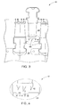
- FIG. 4 is a detailed cross-section view of a portion 46 of the shroud and blade of the steam turbine of FIG. 3.
- the radial clearance between the seal teeth 42 and the shroud 24 is represented by reference numeral 48 and the axial clearance between the teeth 42 and the shroud 24 is represented by reference numeral 50.
- the radial and axial clearances 48 and 50 represent the clearances between the center tooth and the shroud.
- clearances between the other seal teeth and the shroud 24 may be similarly estimated through the present technique.
- the radial clearance 48 may be reduced to zero, leading to interference between the seal teeth 42 and the groove 44.
- the rotor 26 may grow axially with respect to the shroud 24, leading to axial rubbing of the teeth 42 within the groove 44, thus increasing the rate of wear on the components.
- These undesirable interferences also can lead to damage of the components.
- the present technique provides an online measurement of radial and axial clearances 48 and 50, which may be incorporated into a closed-loop control strategy to maintain these clearances at values within acceptable limits.
- the control strategy may include, for example, thermal actuation of the shroud 24, causing it to appropriately expand when the clearance between the shroud 24 and the seal teeth 42 decreases.
- thermal actuators utilize the property of thermal expansion to produce movement of the shroud 24.
- mechanical actuators may be used to compensate for axial growth of the blade 26 within the shroud 24.
- the capacitance between two objects is a function of the overlap surface area and the separation between the two objects.
- the capacitance between the rotor 26 and the shroud 24 is a function of the radial clearance 48 and the overlap area, which in turn is directly proportional to the axial clearance 50 of the seal teeth 42 with respect to the shroud 24.
- the radial clearance 48 between the seal teeth 42 and the shroud 24 changes.
- the seal teeth 42 move axially across the groove 44, the area of the sensor head covered by the seal teeth 42 will change. These changes will result in a change in measured capacitance.
- the change in capacitance can be correlated to axial and radial displacements and hence a composite clearance measurement may be obtained.
- the measurement of radial and axial clearances 48 and 50 via the multi tip clearance measurement system 12 will be further described below with reference to FIGS. 5-6.
- the multi tip clearance measurement system 12 includes a sensor having a plurality of probe tips configured to generate signals representative of a sensed parameter. Additionally, the signals from subsets of the probe tips are evaluated via a processing unit 34 (see FIG. 2) for estimating the clearance between two objects. In particular, the signals from the plurality of probe tips are evaluated against each other to detect an outlier probe tip and to adjust a gain or an offset of the respective outlier probe tip to bring it inline with the other tips for estimating the clearance between the two objects.
- the sensor comprises at least three probe tips.
- the sensor includes at least four probe tips configured to measure radial and axial clearances 48 and 50 between the stationary and rotating components 24 and 26 as described below with reference to FIG. 5.
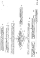
- FIG. 5 illustrates a plan view of an exemplary configuration 60 of the sensors 26, 28 and 30 employed for the multi tip clearance measurement system 12 of FIG. 1.
- the sensor 60 includes a plurality of capacitive probe tips 62, 64, 66 and 68 which may include, for example, electrically conductive shafts.
- the illustrated geometry and relative locations of the probes 62, 64, 66 and 68 facilitate measurement of a large axial displacement range, for example, in excess of 0.5 inches, while providing a desirable resolution for radial measurements, for example, for measuring displacements on the order of 0.01 inches.
- the above feature is advantageous in applications where the axial displacements of the rotating component 14 (see FIG. 1) are substantially larger than the radial displacements with respect to the shroud 16 (see FIG.
- the senor 60 may include oval elements. In an alternate embodiment, the sensor 60 may include overlapping triangular elements.
- the probes 62, 64, 66 and 68 are positioned in a staggered manner, having a diamond shaped configuration, on the sensor head to maximize sensitivity to change in overlap area.
- Other staggered configurations may be conceived in embodiments having greater or lesser number of probes.
- the diameters of the probes 62, 64, 66 and 68 at the head or tip portion are suitably large enough to provide adequate overlap surface area between them and the tip of the blade 14.
- the probes 62, 64, 66 and 68 may be formed from a material comprising nickel, aluminum, cobalt, or combinations thereof, such as Kovar.
- a material comprising platinum, rhodium, or combinations thereof may be used for the probes 62, 64, 66 and 68.
- the probe tips 62, 64, 66 and 68 are configured to generate signals representative of capacitance between the stationary and rotating components 16 and 14 (see FIG. 1). Further, the clearance between the stationary and rotating components 16 and 14 is estimated based upon simultaneous subsets of the sensed capacitances from the probe tips 62, 64, 66 and 68. In the illustrated embodiment, each subset includes sensed capacitances from at least two probe tips. As will be appreciated by one skilled in the art, based upon a sensor configuration subsets of sensed parameters for a greater number of probe tips may be envisaged. In an exemplary embodiment, for the probe tip configuration 60 described above, six subsets of the sensed capacitances may be analyzed for the clearance estimation.
- a first subset includes sensed capacitance from probe tips 62 and 64 and a second subset includes sensed capacitances from the probe tips 62 and 66.
- a third subset includes sensed capacitance from probe tips 62 and 68 and a fourth subset includes sensed capacitances from the probe tips 64 and 66.
- a fifth subset includes sensed capacitances from the probe tips 64 and 68 and a sixth subset includes sensed capacitances from the probe tips 66 and 68.
- Another three subsets of three tips each may also be analyzed.
- a clearance look-up is performed for each of the subsets described above via the processing unit 34 (see FIG. 2).
- the processing unit 34 may employ a look-up table, or a calibration curve, or an analytical table, or a calculation, or combinations thereof for estimating the clearance based upon the sensed capacitances.
- some of the subsets may experience a large clearance due to an error or drift and therefore may be eliminated from the evaluation.
- some subsets may be physically far away from the bucket, this have a very small signal present. Typically, the small signal is more likely to be dominated by noise or other such error sources.
- Such subsets may be eliminated from consideration, or may be weighted lower than other subsets.
- the signals are considered to be healthy and the clearance estimation is completed based upon the signals from such subsets.
- the estimated clearance from all the simultaneous subsets is not in agreement then such signals are analyzed to detect an outlier tip among the plurality of probe tips 62, 64, 66 and 68.
- the clearance may be estimated from the signals from the tips other than the outlier tip.
- the clearance may be estimated by processing the signals from the probe tips 62, 66 and 68.
- a gain or an offset of the outlier tip may be adjusted to bring it in agreement with the other probe tips thus correcting for performance drifts that may happen over a period of time.
- the clearance is estimated from the probe tips 62, 66, 68 along with the probe tip 64 with an adjusted gain.
- FIG. 6 is a flow chart illustrating a process 70 of operating the multi tip clearance measurement system 12 of FIG. 1.
- the process includes receiving a plurality of signals from a sensor having a plurality of probe tips, as represented by step 72.
- the plurality of signals are representative of a sensed parameter between first and second objects.
- the sensor includes a capacitive probe and the sensed parameter includes capacitance.
- the sensor includes an eddy current sensor and the sensed parameter includes an induced current.
- a plurality of simultaneous subsets of sensed parameters are formed. In one embodiment, each simultaneous subset includes sensed parameters from at least two probe tips.
- the clearance between the first and second objects is estimated based upon each of the simultaneous subsets of the sensed parameters from the probe tips via a processing unit.
- a look-up table, or a calibration curve, or an analytical table, or a calculation, or combinations thereof may be employed for estimating the clearance based upon the sensed parameters.
- the processing unit determines if the estimated clearance from the simultaneous subsets of sensed parameter are in agreement for all the subsets. If the estimated clearance is in agreement for the subsets, then the clearance processing is completed and the clearance between the first and second objects is estimated based upon signals from all such subsets (step 80). Alternatively, if the estimated clearance from the subsets is not in agreement for all the subsets, then the processing unit determines the outlier probe tip that is contributing to the error in the gain (step 82). It should be noted that the term "gain" refers to the gain of the complete clearance measurement system 12 including the electronics. For example, in one embodiment, if a probe tip erodes and becomes smaller in size, the electronics gain in the system will not change but the overall signal will get smaller thereby contributing to an effect of decrease in the gain of the system.
- the gain or offset of the outlier tip is adjusted to bring it in agreement for the rest of the probe tips, as represented by step 84. Further, as represented by step 86, the clearance is estimated based upon signals from all the probe tips including the outlier probe tip with an adjusted gain or offset. In an alternate embodiment, the signals from the outlier probe tip are eliminated from the clearance estimation and the clearance is estimated based upon the signals from the probe tips other than the outlier tip (steps 88 and 86). It should be noted that the detection of the outlier tip among the plurality of probe tips of the multi tip clearance system facilitates monitoring of health of the clearance measurement system. In one embodiment, the outlier tip may be replaced for an accurate estimation of the clearance from the clearance measurement system. Alternatively, the signals from the outlier probe tip may be eliminated from the clearance estimation, or a gain of the outlier probe tip may be adjusted to correct the error or drift due to the respective probe tip.
- the technique illustrated above may be used for measuring the clearance between rotating and static components in a steam turbine.
- the technique may also be used in certain other applications, for example, for measuring clearance between stationary and rotating components in generators.
- the method described herein may be advantageous for providing accurate measurement of clearance between objects through a multi tip clearance measurement system by using data subsets for error detection and drift tracking of sensor elements thereby reducing the level of signal conditioning required.
- the technique is particularly advantageous to provide a self-calibrating sensor system for accurate clearance measurement of parts, even in operation and over extended periods of time, enabling better clearance control in parts while in operation.
Landscapes
- Engineering & Computer Science (AREA)
- Physics & Mathematics (AREA)
- General Physics & Mathematics (AREA)
- Mechanical Engineering (AREA)
- General Engineering & Computer Science (AREA)
- Measurement Of Length, Angles, Or The Like Using Electric Or Magnetic Means (AREA)
- Turbine Rotor Nozzle Sealing (AREA)
- Length Measuring Devices With Unspecified Measuring Means (AREA)
Abstract
Description
- The invention relates generally to clearance measurement systems, and more particularly to, a multi tip clearance measurement system for measuring a clearance between a stationary component and a movable component of a rotating machine.
- Various types of sensors have been used to measure the distance between two objects. In addition, these sensors have been used in various applications. For example, a steam turbine has a rotating bucket that is disposed adjacent a carrier. The clearance between the rotating bucket and the carrier varies due to various operating conditions, such as changes in temperature, oxidation of the bucket tip, and so forth. It is desirable that a gap or clearance between the rotating bucket and the carrier be maintained during operation of the steam turbine.
- One existing sensor is a multi tip capacitance sensor that includes multiple probe tips to measure capacitance for estimating the radial and axial clearance between stationary and movable components. Typically, the estimated clearance is a function of gain of all the signals from all the probe tips of the sensor. Unfortunately, an error in this gain, or a drift over a period time causes the system performance to deteriorate. Further, certain systems employ signal processing to evaluate the health of the individual signals from the probe tips and transfer functions are used to convert the measured signal to clearance. Again, error correction of individual gain of the probe tips is not addressed in such systems.
- Moreover, these clearance measurement systems are typically employed to measure clearances between components during design and offline testing. Unfortunately, these existing systems are ineffective for in-service measurements due to the noise and drift generated by changes in the geometry of the components, among other factors. Instead, in-service clearance control is based on the clearance measurements previously taken during design and offline testing of components. As the components become worn during service, the offline measurements become ineffective for in-service clearance control.
- Accordingly, a need exists for providing a multi tip clearance measurement system that provides an accurate measurement of clearance between two components by detecting and correcting single tip errors and drifts. It would also be advantageous to provide a self-calibrating clearance measurement system that could be employed for accurate clearance measurement for parts in operation.
- Briefly, according to one embodiment a multi tip clearance measurement system is provided. The clearance measurement system includes a sensor disposed on a first object, wherein the sensor comprises a plurality of probe tips configured to generate signals representative of a sensed parameter corresponding to a second object and a processing unit configured to evaluate the signals from subsets of the sensed parameters from the probe tips to detect an outlier probe tip and to adjust a gain, or an offset of the respective outlier probe tip for estimating the clearance between the first and second objects based upon the signals.
- In another embodiment, a method of measuring clearance between first and second objects is provided. The method includes receiving a plurality of signals representative of a sensed parameter corresponding to the first or second object via a sensor having a plurality of probe tips and estimating the clearance between the first and second objects based upon simultaneous subsets of the sensed parameters from the probe tips. The method also includes analyzing the estimated clearance from the subsets of sensed parameters from the probe tips to detect an outlier probe tip and adjusting a gain, or an offset of the outlier probe tip to estimate the clearance based upon the plurality of signals.
- In another embodiment, a method of measuring clearance between first and second objects is provided. The method includes receiving a plurality of signals representative of a sensed parameter corresponding to the first or second object via a sensor having a plurality of probe tips and estimating the clearance between the first and second objects based upon simultaneous subsets of the sensed parameters from the probe tips. The method also includes analyzing the estimated clearance from the subsets of sensed parameters from the probe tips to detect an outlier probe tip and estimating the clearance based upon the signals from the probe tips other than the outlier probe tip.
- In another embodiment, a rotating machine is provided. The rotating machine includes a rotating component spaced apart from a stationary component and a sensor disposed on the stationary component, wherein the sensor comprises a plurality of probe tips configured to generate signals representative of a sensed parameter corresponding to the rotating component. The rotating machine also includes a processing unit configured to evaluate the signals from subsets of the sensed parameters from the probe tips to detect an outlier probe tip and to adjust a gain, or an offset of the respective outlier probe tip for estimating the clearance between the stationary and rotating components based upon the signals.
- In another embodiment, a method of monitoring health of a multi tip clearance measurement system is provided. The method includes receiving a plurality of signals representative of a sensed parameter corresponding to a first or a second object via a sensor having a plurality of probe tips and storing the plurality of signals received from the plurality of probe tips. The method also includes estimating the clearance between the first and second objects based upon simultaneous subsets of sensed parameters from the probe tips and analyzing the estimated clearance from the subsets of the sensed parameters from the probe tips to detect an outlier probe tip.
- These and other features, aspects, and advantages of the present invention will become better understood when the following detailed description of embodiments, provided by way of example only, is read with reference to the accompanying drawings in which like characters represent like parts throughout the drawings, wherein:
- FIG. 1 is a diagrammatical perspective illustration of a steam turbine having a multi tip clearance measurement system in accordance with embodiments of the present technique;
- FIG. 2 illustrates a perspective view of the steam turbine of FIG. 1 having the multi tip clearance measurement system for measuring the clearance between the rotating buckets and the carrier in accordance with embodiments of the present technique;
- FIG. 3 is a cross-sectional view of a portion of the steam turbine of FIG. 2 wherein the present clearance control technique can be used in accordance with embodiments of the present technique;
- FIG. 4 is a detailed cross-section view of FIG. 3 in accordance with embodiments of the present technique;
- FIG. 5 illustrates an exemplary configuration of sensors employed for the multi tip clearance measurement system of FIG. 1 in accordance with embodiments of the present technique; and
- FIG. 6 is a flow chart illustrating a method of operating the multi tip clearance measurement system of FIG. 1 in accordance with embodiments of the present technique.
- As discussed in detail below, embodiments of the present technique function to provide an accurate measurement of clearance between two objects in various systems such as a steam turbine, a generator, a turbine engine (e.g., airplane turbine engine), a machine having rotating components and so forth. In particular, the present technique employs a signal correlation method for gain error correction in a radial and axial clearance measurement system to detect and correct for probe tip errors and drifts. Referring now to the drawings, FIG. 1 illustrates a
steam turbine 10 having a multi tipclearance measurement system 12 for measuring a clearance between two objects in thesteam turbine 10. In the illustrated embodiment, theclearance measurement system 12 includes a sensor having a plurality of probe tips that is configured for measuring the clearance between a rotating component 14 and astationary component 16 in thesteam turbine 10, which will be described in detail below. - FIG. 2 illustrates a rotating machine, such as a
steam turbine 20 as illustrated in FIG. 1, wherein aspects of the present technique can be incorporated to measure clearance between rotating and stationary components. Thesteam turbine 20 includes arotor 22 disposed within astationary housing 24. A plurality ofturbine blades 26, which may also be referred to as buckets, are affixed to therotor 22. In operation, theblades 26 are subjected to steam at a high temperature and pressure, which causes theblades 26 to rotate about an axis. Theblades 26 rotate within the stationary housing orshroud 24 that is positioned radially and circumferentially around theblades 26. A relatively small clearance exists between theblades 26 and theshroud 24 to facilitate rotation of theblades 26 within theshroud 24, while also preventing excessive leakage of the working fluid, i.e. steam, between theblades 26 and theshroud 24. In accordance with the present technique, one or more clearance sensors, such as represented byreference numerals stationary shroud 24. In the illustrated embodiment, each of theclearance sensors blades 26. Further, the clearance between theblades 26 and theshroud 24 is estimated as a function of the gain of signals from all the probe tips. - In an exemplary embodiment, the
clearance sensors clearance sensors sensors blades 26 with respect to theshroud 24 at their respective circumferential locations. - In the embodiment illustrated in FIG. 2, signals representative of the sensed parameters are detected by the
sensors processing unit 34 for processing the signals. In particular, simultaneous subsets of sensed parameters from the probe tips are evaluated to detect an outlier probe tip for estimating the clearance between theblades 26 and theshroud 24. Moreover, an offset or a gain of the respective outlier probe tip is adjusted to bring it into agreement with the other subsets, and to estimate the clearance between theblades 26 and theshroud 24. Further, the clearance measurement through thesensors shroud 24 and theturbine blades 26 via aclearance control system 36. The technique for detection of the outlier probe tip for each of thesensors - Referring now to FIG. 3, a cross-sectional view is shown for a bottom or
lower portion 40 of thesteam turbine 10 of FIG. 1, illustrating exemplary radial and axial clearance that may be measured by the present technique. In the illustrated embodiment, the tip of theblade 26 includes packing teeth orseal teeth 42 that mesh into agroove 44 provided on the inner circumference of theshroud 24. In a present embodiment, the clearance measurement system 12 (see FIG. 1) may be coupled to theshroud 24 for measuring the radial and axial clearances between the tip of theblade 26 and theshroud 24. - FIG. 4 is a detailed cross-section view of a
portion 46 of the shroud and blade of the steam turbine of FIG. 3. As illustrated, the radial clearance between theseal teeth 42 and theshroud 24 is represented byreference numeral 48 and the axial clearance between theteeth 42 and theshroud 24 is represented byreference numeral 50. In a present embodiment, the radial andaxial clearances shroud 24 may be similarly estimated through the present technique. - In certain embodiments, due to differences in the rate of thermal expansion of the
shroud 24 and therotor 26, there is a potential that theradial clearance 48 may be reduced to zero, leading to interference between theseal teeth 42 and thegroove 44. Further, due to this differential rate of expansion, therotor 26 may grow axially with respect to theshroud 24, leading to axial rubbing of theteeth 42 within thegroove 44, thus increasing the rate of wear on the components. These undesirable interferences also can lead to damage of the components. The present technique provides an online measurement of radial andaxial clearances shroud 24, causing it to appropriately expand when the clearance between theshroud 24 and theseal teeth 42 decreases. In this embodiment, thermal actuators utilize the property of thermal expansion to produce movement of theshroud 24. In certain other embodiments, mechanical actuators may be used to compensate for axial growth of theblade 26 within theshroud 24. - As will be appreciated by those of ordinary skill in the art, the capacitance between two objects is a function of the overlap surface area and the separation between the two objects. In the present embodiment, the capacitance between the
rotor 26 and theshroud 24 is a function of theradial clearance 48 and the overlap area, which in turn is directly proportional to theaxial clearance 50 of theseal teeth 42 with respect to theshroud 24. As therotor 26 expands radially, theradial clearance 48 between theseal teeth 42 and theshroud 24 changes. Similarly, as theseal teeth 42 move axially across thegroove 44, the area of the sensor head covered by theseal teeth 42 will change. These changes will result in a change in measured capacitance. In accordance with aspects of the present technique discussed below, the change in capacitance can be correlated to axial and radial displacements and hence a composite clearance measurement may be obtained. The measurement of radial andaxial clearances clearance measurement system 12 will be further described below with reference to FIGS. 5-6. - As described before, the multi tip
clearance measurement system 12 includes a sensor having a plurality of probe tips configured to generate signals representative of a sensed parameter. Additionally, the signals from subsets of the probe tips are evaluated via a processing unit 34 (see FIG. 2) for estimating the clearance between two objects. In particular, the signals from the plurality of probe tips are evaluated against each other to detect an outlier probe tip and to adjust a gain or an offset of the respective outlier probe tip to bring it inline with the other tips for estimating the clearance between the two objects. In an exemplary embodiment, the sensor comprises at least three probe tips. In another embodiment, the sensor includes at least four probe tips configured to measure radial andaxial clearances rotating components - FIG. 5 illustrates a plan view of an
exemplary configuration 60 of thesensors clearance measurement system 12 of FIG. 1. In the illustrated embodiment, thesensor 60 includes a plurality ofcapacitive probe tips probes sensor 60 may include oval elements. In an alternate embodiment, thesensor 60 may include overlapping triangular elements. - In the illustrated embodiment, the
probes probes probes probes - The
probe tips rotating components 16 and 14 (see FIG. 1). Further, the clearance between the stationary androtating components 16 and 14 is estimated based upon simultaneous subsets of the sensed capacitances from theprobe tips probe tip configuration 60 described above, six subsets of the sensed capacitances may be analyzed for the clearance estimation. For example, in the illustrated embodiment, a first subset includes sensed capacitance fromprobe tips probe tips probe tips probe tips probe tips probe tips - In operation, a clearance look-up is performed for each of the subsets described above via the processing unit 34 (see FIG. 2). The
processing unit 34 may employ a look-up table, or a calibration curve, or an analytical table, or a calculation, or combinations thereof for estimating the clearance based upon the sensed capacitances. In certain embodiments, some of the subsets may experience a large clearance due to an error or drift and therefore may be eliminated from the evaluation. Depending on the axial position, some subsets may be physically far away from the bucket, this have a very small signal present. Typically, the small signal is more likely to be dominated by noise or other such error sources. Such subsets may be eliminated from consideration, or may be weighted lower than other subsets. If the estimated clearance from all the remaining simultaneous subsets is in agreement then the signals are considered to be healthy and the clearance estimation is completed based upon the signals from such subsets. Alternatively, if the estimated clearance from all the simultaneous subsets is not in agreement then such signals are analyzed to detect an outlier tip among the plurality ofprobe tips - For example, if the sensed capacitances from the first and fourth subsets including
probe tips probe tip 64 is detected to be the outlier tip. In one embodiment, the clearance may be estimated from the signals from the tips other than the outlier tip. For example, in this embodiment, the clearance may be estimated by processing the signals from theprobe tips probe tips probe tip 64 with an adjusted gain. - FIG. 6 is a flow chart illustrating a
process 70 of operating the multi tipclearance measurement system 12 of FIG. 1. The process includes receiving a plurality of signals from a sensor having a plurality of probe tips, as represented bystep 72. The plurality of signals are representative of a sensed parameter between first and second objects. In one embodiment, the sensor includes a capacitive probe and the sensed parameter includes capacitance. Alternatively, the sensor includes an eddy current sensor and the sensed parameter includes an induced current. At step 74, a plurality of simultaneous subsets of sensed parameters are formed. In one embodiment, each simultaneous subset includes sensed parameters from at least two probe tips. Further, as represented by step 76, the clearance between the first and second objects is estimated based upon each of the simultaneous subsets of the sensed parameters from the probe tips via a processing unit. In certain embodiments, a look-up table, or a calibration curve, or an analytical table, or a calculation, or combinations thereof may be employed for estimating the clearance based upon the sensed parameters. - At
step 78, the processing unit determines if the estimated clearance from the simultaneous subsets of sensed parameter are in agreement for all the subsets. If the estimated clearance is in agreement for the subsets, then the clearance processing is completed and the clearance between the first and second objects is estimated based upon signals from all such subsets (step 80). Alternatively, if the estimated clearance from the subsets is not in agreement for all the subsets, then the processing unit determines the outlier probe tip that is contributing to the error in the gain (step 82). It should be noted that the term "gain" refers to the gain of the completeclearance measurement system 12 including the electronics. For example, in one embodiment, if a probe tip erodes and becomes smaller in size, the electronics gain in the system will not change but the overall signal will get smaller thereby contributing to an effect of decrease in the gain of the system. - In one embodiment, the gain or offset of the outlier tip is adjusted to bring it in agreement for the rest of the probe tips, as represented by
step 84. Further, as represented bystep 86, the clearance is estimated based upon signals from all the probe tips including the outlier probe tip with an adjusted gain or offset. In an alternate embodiment, the signals from the outlier probe tip are eliminated from the clearance estimation and the clearance is estimated based upon the signals from the probe tips other than the outlier tip (steps 88 and 86). It should be noted that the detection of the outlier tip among the plurality of probe tips of the multi tip clearance system facilitates monitoring of health of the clearance measurement system. In one embodiment, the outlier tip may be replaced for an accurate estimation of the clearance from the clearance measurement system. Alternatively, the signals from the outlier probe tip may be eliminated from the clearance estimation, or a gain of the outlier probe tip may be adjusted to correct the error or drift due to the respective probe tip. - The various aspects of the method described hereinabove have utility in different applications. For example, the technique illustrated above may be used for measuring the clearance between rotating and static components in a steam turbine. The technique may also be used in certain other applications, for example, for measuring clearance between stationary and rotating components in generators. As above, even more generally, the method described herein may be advantageous for providing accurate measurement of clearance between objects through a multi tip clearance measurement system by using data subsets for error detection and drift tracking of sensor elements thereby reducing the level of signal conditioning required. Further, the technique is particularly advantageous to provide a self-calibrating sensor system for accurate clearance measurement of parts, even in operation and over extended periods of time, enabling better clearance control in parts while in operation.
- While only certain features of the invention have been illustrated and described herein, many modifications and changes will occur to those skilled in the art. It is, therefore, to be understood that the appended claims are intended to cover all such modifications and changes as fall within the true spirit of the invention.
Claims (10)
- A multi tip clearance measurement system (12), comprising:a sensor (28) disposed on a first object (24), wherein the sensor comprises a plurality of probe tips (62, 64, 66, 68) configured to generate signals representative of a sensed parameter corresponding to a second object (26); anda processing unit (34) configured to evaluate the signals from subsets of the sensed parameters from the probe tips (62, 64, 66, 68) to detect an outlier probe tip and to adjust a gain, or an offset of the respective outlier probe tip for estimating the clearance between the first and second objects (24, 26) based upon the signals.
- The system of claim 1, wherein the sensor (28) comprises at least three probe tips.
- The system of claim 1, wherein the processing unit (34) is configured to estimate the clearance between the first and second objects (24, 26) by processing the signals corresponding to the probe tips other than the outlier probe tip.
- The system of claim 1, wherein the sensor (28) comprises a capacitive sensor and wherein the sensed parameter comprises a capacitance.
- The system of claim 1, wherein the sensor (28) comprises an eddy current sensor and wherein the sensed parameter comprises an induced current.
- The system of claim 1, wherein the processing unit (34) comprises a look-up table, or a calibration curve, or an analytical model, or a calculation, or combinations thereof for estimating clearance and for detecting the outlier probe tip based upon the signals from the subsets of sensed parameters from the probe tips (62, 64, 66, 68).
- A method of measuring clearance between first and second objects, comprising:receiving a plurality of signals representative of a sensed parameter corresponding to the first or second object via a sensor having a plurality of probe tips;estimating the clearance between the first and second objects based upon simultaneous subsets of the sensed parameters from the probe tips;analyzing the estimated clearance from the subsets of the sensed parameters from the probe tips to detect an outlier probe tip; andadjusting a gain, or an offset of the outlier probe tip to estimate the clearance based upon the plurality of signals.
- A method of measuring clearance between first and second objects, comprising:receiving a plurality of signals representative of a sensed parameter corresponding to the first or second object via a sensor having a plurality of probe tips;estimating the clearance between the first and second objects based upon simultaneous subsets of the sensed parameters from the probe tips;analyzing the estimated clearance from the subsets of the sensed parameters from the probe tips to detect an outlier probe tip; andestimating the clearance based upon the signals from the probe tips other than the outlier probe tip.
- A rotating machine (20), comprising:a rotating component (22) spaced apart from a stationary component (24);a sensor (28) disposed on the stationary component (24), wherein the sensor (28) comprises a plurality of probe tips (62, 64, 66, 68) configured to generate signals representative of a sensed parameter corresponding to the rotating component (22); anda processing unit (34) configured to evaluate the signals from subsets of the sensed parameters from the probe tips (62, 64, 66, 68) to detect an outlier probe tip and to adjust a gain, or an offset of the respective outlier probe tip for estimating the clearance between the stationary and rotating components (22, 24) based upon the signals.
- A method of monitoring health of a multi tip clearance measurement system, comprising:receiving a plurality of signals representative of a sensed parameter corresponding to a first or a second object via a sensor having a plurality of probe tips;storing the plurality of signals received from the plurality of probe tips;estimating the clearance between the first and second objects based upon simultaneous subsets of sensed parameters from the probe tips; andanalyzing the estimated clearance from the subsets of sensed parameters from the probe tips to detect an outlier probe tip.
Applications Claiming Priority (1)
| Application Number | Priority Date | Filing Date | Title |
|---|---|---|---|
| US11/393,584 US7215129B1 (en) | 2006-03-30 | 2006-03-30 | Multi tip clearance measurement system and method of operation |
Publications (1)
| Publication Number | Publication Date |
|---|---|
| EP1840499A1 true EP1840499A1 (en) | 2007-10-03 |
Family
ID=38001007
Family Applications (1)
| Application Number | Title | Priority Date | Filing Date |
|---|---|---|---|
| EP07104728A Withdrawn EP1840499A1 (en) | 2006-03-30 | 2007-03-23 | Multi tip clearance measurement system and method of operation |
Country Status (5)
| Country | Link |
|---|---|
| US (1) | US7215129B1 (en) |
| EP (1) | EP1840499A1 (en) |
| JP (1) | JP2007271625A (en) |
| KR (1) | KR20070099440A (en) |
| CN (1) | CN101046367A (en) |
Families Citing this family (38)
| Publication number | Priority date | Publication date | Assignee | Title |
|---|---|---|---|---|
| US7762153B2 (en) * | 2007-05-31 | 2010-07-27 | General Electric Company | Method and systems for measuring blade deformation in turbines |
| US8177474B2 (en) * | 2007-06-26 | 2012-05-15 | General Electric Company | System and method for turbine engine clearance control with rub detection |
| US7787996B2 (en) * | 2008-01-10 | 2010-08-31 | General Electric Company | Determining optimal turbine operating temperature based on creep rate data and predicted revenue data |
| US7852092B2 (en) * | 2008-03-25 | 2010-12-14 | General Electric Company | Systems for inspection of shrouds |
| US7994800B2 (en) * | 2008-03-25 | 2011-08-09 | General Electric Company | Systems and methods for online phase calibration |
| US8272246B2 (en) * | 2008-09-30 | 2012-09-25 | General Electric Company | Electronic self-calibration for sensor clearance |
| US8022715B2 (en) * | 2009-01-27 | 2011-09-20 | General Electric Company | Automated sensor specific calibration through sensor parameter download |
| US8121813B2 (en) * | 2009-01-28 | 2012-02-21 | General Electric Company | System and method for clearance estimation between two objects |
| JP5593052B2 (en) * | 2009-10-09 | 2014-09-17 | ゼネラル・エレクトリック・カンパニイ | Electronic self-calibration of sensor clearance |
| US8230726B2 (en) | 2010-03-31 | 2012-07-31 | General Electric Company | Methods, systems and apparatus relating to tip clearance calculations in turbine engines |
| US8593296B2 (en) * | 2010-10-19 | 2013-11-26 | General Electric Company | System and method for turbine bucket tip shroud deflection measurement |
| FR2977316B1 (en) * | 2011-07-01 | 2014-02-21 | Snecma | DEVICE AND METHOD FOR MEASURING THE TIME OF PASSING AUBES INTO A TURBOMACHINE |
| US8876460B2 (en) | 2011-08-11 | 2014-11-04 | General Electric Company | Method and apparatus for measuring turbine shell clearance |
| GB2495104A (en) * | 2011-09-28 | 2013-04-03 | Oxford Rf Sensors Ltd | Rotor blade sensor |
| US9037434B2 (en) * | 2012-01-03 | 2015-05-19 | General Electric Company | Method and apparatus for obtaining discrete axial clearance data using radial clearance sensors |
| US8970228B2 (en) * | 2012-05-31 | 2015-03-03 | General Electric Company | Rotational clearance measurement system and method of operation |
| GB201212252D0 (en) * | 2012-07-10 | 2012-08-22 | Isis Innovation | Turbo-machine assembly |
| US10077992B2 (en) | 2012-08-31 | 2018-09-18 | United Technologies Corporation | Tip clearance probe including anti-rotation feature |
| US9316479B2 (en) * | 2012-09-20 | 2016-04-19 | United Technologies Corporation | Capacitance based clearance probe and housing |
| US9518850B2 (en) * | 2012-09-28 | 2016-12-13 | United Technologies Corporation | Embedded cap probe |
| US9417048B2 (en) | 2012-10-31 | 2016-08-16 | General Electric Company | Capacitive sensor device and method of manufacture |
| CN102997885B (en) * | 2012-11-27 | 2015-02-25 | 安徽工业大学 | Gap detection device of large slewing bearing |
| US9250056B2 (en) * | 2012-12-31 | 2016-02-02 | General Electric Company | System and method for monitoring health of airfoils |
| US10125682B2 (en) * | 2013-02-26 | 2018-11-13 | Rolls-Royce Corporation | Methods and apparatus for measuring axial shaft displacement within gas turbine engines |
| JP6604939B2 (en) | 2013-03-15 | 2019-11-13 | ユナイテッド テクノロジーズ コーポレイション | Control system, control method and gas turbine engine |
| US9297271B2 (en) | 2013-04-29 | 2016-03-29 | General Electric Company | Turbine blade monitoring arrangement and method of manufacturing |
| EP2806110A1 (en) * | 2013-05-22 | 2014-11-26 | MTU Aero Engines GmbH | Turbo engine stage and method for determining a seal gap of such a turbo engine stage |
| US9476318B2 (en) * | 2013-09-03 | 2016-10-25 | General Electric Company | Systems and methods to monitor a rotating component |
| US9587511B2 (en) | 2013-12-13 | 2017-03-07 | General Electric Company | Turbomachine cold clearance adjustment |
| EP3034994B1 (en) * | 2014-12-19 | 2017-08-23 | Rolls-Royce plc | System and method for measuring over tip leakage |
| CN105526878B (en) * | 2016-01-16 | 2018-02-02 | 东北电力大学 | The real time dynamic measurement method of radial clearance between a kind of turbine rotor and stator |
| US10330455B2 (en) | 2016-09-19 | 2019-06-25 | United Technologies Corporation | Tri-axial capacitance probe with case integrated housing |
| CN106482694A (en) * | 2016-12-06 | 2017-03-08 | 中国航空工业集团公司北京长城计量测试技术研究所 | Tip clearance measurement sensor dynamic calibration apparatus under hot environment |
| CN108020420A (en) * | 2017-12-01 | 2018-05-11 | 中国航发沈阳黎明航空发动机有限责任公司 | A kind of measuring method of aero-engine rotation shaft clearance |
| US10663280B2 (en) * | 2018-03-23 | 2020-05-26 | General Electric Company | System and method for measuring eccentricity of gas turbine casing relative to rotor |
| CN109737911B (en) * | 2019-01-07 | 2020-08-14 | 烽火通信科技股份有限公司 | Calibration tool, and device and method for measuring blind-mate connector mutual-matching gap |
| CN110375630B (en) * | 2019-07-23 | 2021-02-09 | 杭州申昊科技股份有限公司 | Adjusting structure of eddy current sensor |
| CN115235404B (en) * | 2022-09-22 | 2022-12-06 | 中国航发燃气轮机有限公司 | Rotor and stator clearance correction method for heavy gas turbine |
Citations (3)
| Publication number | Priority date | Publication date | Assignee | Title |
|---|---|---|---|---|
| US20030011378A1 (en) * | 2001-07-11 | 2003-01-16 | Seiichiro Ishio | Capacitive sensor apparatus |
| JP2005134131A (en) * | 2003-10-28 | 2005-05-26 | Oki Electric Ind Co Ltd | Capacitance type distance measuring instrument |
| EP1640687A1 (en) * | 2004-09-28 | 2006-03-29 | General Electric Company | Multi-range capacitive distance sensor and method of oparating the same |
Family Cites Families (6)
| Publication number | Priority date | Publication date | Assignee | Title |
|---|---|---|---|---|
| US4063167A (en) | 1976-06-07 | 1977-12-13 | Avco Corporation | Blade tip clearance measuring apparatus |
| US4847556A (en) * | 1986-09-08 | 1989-07-11 | Langley Lawrence W | Eddy current clearance transducing system |
| US4806848A (en) | 1987-03-11 | 1989-02-21 | The United States Of America As Represented By The Secretary Of The Air Force | Compressor blade clearance measurement system |
| US5723980A (en) | 1995-06-07 | 1998-03-03 | Aerogage Corporation | Clearance measurement system |
| WO1999067758A1 (en) * | 1998-06-22 | 1999-12-29 | Martin Daumer | Method and device for detecting drifts, jumps and/or outliers of measurement values |
| US6692222B2 (en) | 2002-05-14 | 2004-02-17 | The Board Of Trustees Of The Leland Stanford Junior University | Micro gas turbine engine with active tip clearance control |
-
2006
- 2006-03-30 US US11/393,584 patent/US7215129B1/en not_active Expired - Fee Related
-
2007
- 2007-03-23 EP EP07104728A patent/EP1840499A1/en not_active Withdrawn
- 2007-03-29 KR KR1020070031059A patent/KR20070099440A/en not_active Withdrawn
- 2007-03-29 JP JP2007088560A patent/JP2007271625A/en not_active Withdrawn
- 2007-03-30 CN CNA2007100921849A patent/CN101046367A/en active Pending
Patent Citations (3)
| Publication number | Priority date | Publication date | Assignee | Title |
|---|---|---|---|---|
| US20030011378A1 (en) * | 2001-07-11 | 2003-01-16 | Seiichiro Ishio | Capacitive sensor apparatus |
| JP2005134131A (en) * | 2003-10-28 | 2005-05-26 | Oki Electric Ind Co Ltd | Capacitance type distance measuring instrument |
| EP1640687A1 (en) * | 2004-09-28 | 2006-03-29 | General Electric Company | Multi-range capacitive distance sensor and method of oparating the same |
Also Published As
| Publication number | Publication date |
|---|---|
| CN101046367A (en) | 2007-10-03 |
| US7215129B1 (en) | 2007-05-08 |
| KR20070099440A (en) | 2007-10-09 |
| JP2007271625A (en) | 2007-10-18 |
Similar Documents
| Publication | Publication Date | Title |
|---|---|---|
| US7215129B1 (en) | Multi tip clearance measurement system and method of operation | |
| US7333913B2 (en) | Clearance measurement system and method of operation | |
| US8591188B2 (en) | Displacement sensor system and method of operation | |
| US8970228B2 (en) | Rotational clearance measurement system and method of operation | |
| US7722310B2 (en) | System and method for measuring clearance between two objects | |
| US8177474B2 (en) | System and method for turbine engine clearance control with rub detection | |
| US8225671B2 (en) | Apparatus and method for non-contacting blade oscillation measurement | |
| EP2578811B1 (en) | Method for determining position of rotating blades having variable thickness. | |
| EP2261614B1 (en) | Combined amplitude and frequency measurements for non-contacting turbomachinery blade vibration | |
| US4876505A (en) | Apparatus and method for monitoring steam turbine shroud clearance | |
| US9341462B2 (en) | Sensor for measuring blade tip clearance in gas turbines | |
| EP2236977A1 (en) | Time-indicating rub pin for transient clearance measurement and related method | |
| CN113242946B (en) | Method of operating a dry gas seal monitoring system | |
| KR960007827B1 (en) | How to eliminate sensor drift in vibration monitoring systems | |
| US9395171B2 (en) | Capacitive sensor with orthogonal fields | |
| US9823145B2 (en) | Bearing nut for measuring the rotational speed of a shaft connected to a turbomachine and associated measuring device | |
| US20140126993A1 (en) | Device and a method for measuring the times of passage of blade tips in a turbine engine | |
| JP6978911B2 (en) | Blade monitoring system, blade monitoring device, blade monitoring method, program | |
| CN114902031A (en) | Method, device, system, aircraft and computer program product for monitoring a turbomachine | |
| CA2555480C (en) | Clearance measurement system and method of operation | |
| RU2648284C2 (en) | Method of measuring radial gap between the ends of impeller blades and gas-turbine engine stator |
Legal Events
| Date | Code | Title | Description |
|---|---|---|---|
| PUAI | Public reference made under article 153(3) epc to a published international application that has entered the european phase |
Free format text: ORIGINAL CODE: 0009012 |
|
| AK | Designated contracting states |
Kind code of ref document: A1 Designated state(s): AT BE BG CH CY CZ DE DK EE ES FI FR GB GR HU IE IS IT LI LT LU LV MC MT NL PL PT RO SE SI SK TR |
|
| AX | Request for extension of the european patent |
Extension state: AL BA HR MK YU |
|
| 17P | Request for examination filed |
Effective date: 20080403 |
|
| 17Q | First examination report despatched |
Effective date: 20080513 |
|
| AKX | Designation fees paid |
Designated state(s): DE FR GB |
|
| STAA | Information on the status of an ep patent application or granted ep patent |
Free format text: STATUS: THE APPLICATION IS DEEMED TO BE WITHDRAWN |
|
| 18D | Application deemed to be withdrawn |
Effective date: 20091001 |