EP1840439A2 - Clamping device - Google Patents
Clamping device Download PDFInfo
- Publication number
- EP1840439A2 EP1840439A2 EP07251043A EP07251043A EP1840439A2 EP 1840439 A2 EP1840439 A2 EP 1840439A2 EP 07251043 A EP07251043 A EP 07251043A EP 07251043 A EP07251043 A EP 07251043A EP 1840439 A2 EP1840439 A2 EP 1840439A2
- Authority
- EP
- European Patent Office
- Prior art keywords
- clamping device
- members
- clamped
- clamping
- articles
- Prior art date
- Legal status (The legal status is an assumption and is not a legal conclusion. Google has not performed a legal analysis and makes no representation as to the accuracy of the status listed.)
- Granted
Links
Images


Classifications
-
- F—MECHANICAL ENGINEERING; LIGHTING; HEATING; WEAPONS; BLASTING
- F16—ENGINEERING ELEMENTS AND UNITS; GENERAL MEASURES FOR PRODUCING AND MAINTAINING EFFECTIVE FUNCTIONING OF MACHINES OR INSTALLATIONS; THERMAL INSULATION IN GENERAL
- F16L—PIPES; JOINTS OR FITTINGS FOR PIPES; SUPPORTS FOR PIPES, CABLES OR PROTECTIVE TUBING; MEANS FOR THERMAL INSULATION IN GENERAL
- F16L23/00—Flanged joints
- F16L23/04—Flanged joints the flanges being connected by members tensioned in the radial plane
- F16L23/08—Flanged joints the flanges being connected by members tensioned in the radial plane connection by tangentially arranged pin and nut
-
- F—MECHANICAL ENGINEERING; LIGHTING; HEATING; WEAPONS; BLASTING
- F16—ENGINEERING ELEMENTS AND UNITS; GENERAL MEASURES FOR PRODUCING AND MAINTAINING EFFECTIVE FUNCTIONING OF MACHINES OR INSTALLATIONS; THERMAL INSULATION IN GENERAL
- F16L—PIPES; JOINTS OR FITTINGS FOR PIPES; SUPPORTS FOR PIPES, CABLES OR PROTECTIVE TUBING; MEANS FOR THERMAL INSULATION IN GENERAL
- F16L21/00—Joints with sleeve or socket
- F16L21/06—Joints with sleeve or socket with a divided sleeve or ring clamping around the pipe ends
- F16L21/065—Joints with sleeve or socket with a divided sleeve or ring clamping around the pipe ends tightened by tangentially-arranged threaded pins
-
- F—MECHANICAL ENGINEERING; LIGHTING; HEATING; WEAPONS; BLASTING
- F01—MACHINES OR ENGINES IN GENERAL; ENGINE PLANTS IN GENERAL; STEAM ENGINES
- F01N—GAS-FLOW SILENCERS OR EXHAUST APPARATUS FOR MACHINES OR ENGINES IN GENERAL; GAS-FLOW SILENCERS OR EXHAUST APPARATUS FOR INTERNAL-COMBUSTION ENGINES
- F01N13/00—Exhaust or silencing apparatus characterised by constructional features
- F01N13/18—Construction facilitating manufacture, assembly, or disassembly
- F01N13/1838—Construction facilitating manufacture, assembly, or disassembly characterised by the type of connection between parts of exhaust or silencing apparatus, e.g. between housing and tubes, between tubes and baffles
- F01N13/1844—Mechanical joints
- F01N13/1855—Mechanical joints the connection being realised by using bolts, screws, rivets or the like
-
- F—MECHANICAL ENGINEERING; LIGHTING; HEATING; WEAPONS; BLASTING
- F01—MACHINES OR ENGINES IN GENERAL; ENGINE PLANTS IN GENERAL; STEAM ENGINES
- F01N—GAS-FLOW SILENCERS OR EXHAUST APPARATUS FOR MACHINES OR ENGINES IN GENERAL; GAS-FLOW SILENCERS OR EXHAUST APPARATUS FOR INTERNAL-COMBUSTION ENGINES
- F01N13/00—Exhaust or silencing apparatus characterised by constructional features
- F01N13/18—Construction facilitating manufacture, assembly, or disassembly
- F01N13/1872—Construction facilitating manufacture, assembly, or disassembly the assembly using stamp-formed parts or otherwise deformed sheet-metal
-
- F—MECHANICAL ENGINEERING; LIGHTING; HEATING; WEAPONS; BLASTING
- F02—COMBUSTION ENGINES; HOT-GAS OR COMBUSTION-PRODUCT ENGINE PLANTS
- F02B—INTERNAL-COMBUSTION PISTON ENGINES; COMBUSTION ENGINES IN GENERAL
- F02B67/00—Engines characterised by the arrangement of auxiliary apparatus not being otherwise provided for, e.g. the apparatus having different functions; Driving auxiliary apparatus from engines, not otherwise provided for
- F02B67/10—Engines characterised by the arrangement of auxiliary apparatus not being otherwise provided for, e.g. the apparatus having different functions; Driving auxiliary apparatus from engines, not otherwise provided for of charging or scavenging apparatus
Definitions
- This invention relates to a clamping device for clamping two or more articles together.
- a G-clamp comprising two semi-circular segments hinged together at a first end to allow the segments to pivot relative to each other between clamped and unclamped positions.
- the second or free ends of the segments can be engaged together via a nut and bolt to maintain the segments in the clamped position.
- the flanged portions of the turbo charger and the exhaust pipe are brought into abutting relationship and held together via a first user in a required position.
- a second user locates the members of the G-clamp around the flanged portions and moves the engagement nut and bolt into engagement position to clamp the G-clamp around the flanged portions.
- a problem with the above method is that it typically requires two people to use the clamp, thereby being a labour intensive and expensive process to undertake.
- a clamping device for clamping two or more articles together, said clamping device including two or more members movable between an unclamped position and a clamped position, characterised in that resilient biasing means are provided on or associated with said clamping device to bias the two or more members to said clamped position in use.
- the biasing means allows the device to automatically move to a clamped position when fitted, thereby removing the requirement of a user manually moving the same to a clamped position. This makes the clamping device easier and quicker to use and can be fitted by a single user.
- one or more ends of a member are typically located a spaced distance apart from an adjacent member.
- the one or more ends of said member are moved into engagement with, into abutting relationship with and/or moved such that the spaced distance is reduced with respect to an adjacent member.
- Movement of the members from the unclamped position to the clamped position typically reduces the diameter or dimensions defined by or within said members, thereby allowing clamping of two or more articles located within said clamping members.
- at least one aperture can be defined by or between said members and the dimensions of said aperture are reduced when said device moves from said unclamped to said clamped position.
- the two or more members are hingedly or pivotably connected to each other, directly or indirectly, to allow rotation or pivoting of said members between said clamped and unclamped positions.
- ends of the members can be movably mounted via a link plate.
- the link plate typically includes a plate including one or more apertures defined therein, such as an aperture defined at each end of the plate.
- the ends of the members are typically movably mounted in the apertures.
- connection means are connected together by connection means and said connection means are movable to allow the members to move between said clamped and unclamped positions.
- the resilient biasing means can include any or any combination of one or more springs, sprung material, elastic, rubber and/or the like.
- the resilient biasing means are provided over, across or are associated with the connection point or points connecting the two or more members together, such as for example, over the hinge joining the two members together.
- the biasing means typically provide a compressive force over or across the connection means of the members biasing the members together.
- engagement means can be provided to maintain the members in at least a clamped position.
- the engagement means can be associated with the connection means, link plate and/or hinge or pivot connection but preferably the engagement means are associated with free ends of the members, and preferably opposite to the hinge or pivot connection.
- the engagement means can, in one embodiment be used to maintain the members in an unclamped position.
- the engagement means can include any or any combination of one or more clips, ties, welding, adhesive, nut and bolt, screw and/or the like.
- separation means can be provided to maintain said members in an unclamped position.
- the separation means are provided between the free ends of the two or more members.
- the separation means are typically detachably attached to the device or to one or more members of the device, such that removal of said separation means moves the members from an unclamped position to a clamped position under the bias of the resilient biasing means.
- the separation means are of such a form so as to provide sufficient force to overcome the bias of the resilient biasing means when fitted to the device.
- the separation means can include any or any combination of one or more screws, clips, bolts and/or the like.
- the resilient biasing means can be attached to the device via any suitable means, such as adhesive, welding, one or more screws, nut & bolt, inter-engaging means and/or the like. In one embodiment the resilient biasing means are detachably attached to said device.
- the clamping device is provided with mounting means for allowing the device to be mounted in, on or with respect to a required position or surface in use.
- the device is typically mounted prior to movement of the device from the unclamped to the clamped position.
- the mounting means typically protrudes outwardly from a surface of the device to allow a substantial part of the device to be mounted a spaced distance from a suitable surface or article.
- the mounting means is in the form of or includes a plate, such as a weld plate, to allow the device to be welded in a required location prior to actuation of the clamping device.
- the mounting means can be attached to one or more of the members, to the resilient biasing means, to connection means connecting the members together and/or the like.
- the clamping device is in the form of a G-clamp with two substantially semi-circular members, the two members being preferably hingedly connected together.
- a clamping device for clamping two or more articles together, said clamping device including two or more members movable between an unclamped position and a clamped position, characterised in that mounting means are provided on or associated with said clamping device to allow the device to be mounted on or relative to one or more of said articles prior to actuation of said clamping device.
- the mounting means allows the clamping device to be mounted to a suitable surface in the locality in which it is to be fitted prior to moving the clamping device between unclamped and clamped positions. As such, a user can mount the device and then have their hands free to actuate the clamping device and/or move the two articles together with respect to the clamping device to a required position without the need to have an additional user to help fit the same.
- the mounting means and resilient biasing means can be used independently of each other or in combination with each other to provide an improved clamping device.
- a method of using a clamping device for clamping two or more articles together said clamping device including two or more members movable between an unclamped position and a clamped position and said method including the steps of locating the device around said articles being clamped and allowing said members to move from said unclamped position to said clamped position under the resilient biasing force of resilient biasing means provided on or associated with said clamping device.
- a method of using a clamping device for clamping two or more articles together said clamping device including two or more members movable between an unclamped position and a clamped position and said method including the steps of mounting the device to a surface on or relative to one of the articles to be clamped using mounting means provided on or associated with said clamping device prior to actuation of said clamping device.
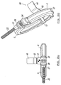
- FIG. 1-2g there is illustrated a clamping device in the form of a G-clamp 2 having first and second members or segments 4, 6.
- the G-clamp is used to clamp two or more flanged articles together.
- First and second members 4, 6 are hingedly connected at ends 8, 10 thereof via a link member 12 having slots 14 defined therein for location of ends 8, 10 therethrough.
- the free ends 8, 10 are formed into a hook 16 to prevent removal of the same from link member 12.
- members 4, 6 can be pivoted about link member 12 between clamped and unclamped positions.
- Ends 18, 20 of members 4, 6, opposite to ends 8, 10 respectively, are joined together via engagement means in the form of a nut 21 and bolt 22 which passes through an aperture defined in end plates 24, 26 of ends 18, 20. More particularly, end plates 24, 26 protrude outwardly of the aperture 28 defined between members 4, 6, such that said plates are substantially parallel to each other.
- the nut and bolt 21, 22 allows the members 4, 6 to be maintained in a clamped position and can also be used to restrict pivotal movement of the members 4, 6 in the unclamped position.
- ends 18, 20 are a spaced distance apart and the dimensions of aperture 28 are relatively large, thereby allowing members 4, 6 to be located around two flanged articles.
- ends 18, 20 are moved towards each other such that they engage, abut or are a smaller distance apart than in the unclamped position to allow the two flanged articles to be secured together.
- the dimensions of aperture 28 are reduced, thereby providing a clamping force on the two flanged articles around which the device is placed.
- members 4, 6 are substantially semi-circular in form such that when joined together form a substantially circular aperture 28 between the same. End plates 24, 26 are formed to protrude outwardly of aperture 28 and are substantially perpendicular to the semi-circular member end to which they communicate with, are joined to or are integral with.
- members 4, 6 could be any suitable shape to form an aperture of any suitable shape, such as square, rectangular and/or the like.
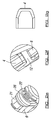
- resilient biasing means in the form of sprung closure clip 30 is joined to members 4, 6 to bias the members to a clamped position. More particularly, clip 30 has end portions 32, 34, joined to the outer surface of members 4, 6 via spot welding. A middle portion 36 is provided between end portions 32, 34 and is located over hinge link member 12. Clip 30 biases members 4, 6 to the clamped position, such that when the clips are located in position around the two articles to be joined together, the clip automatically clamps the members around said articles. The engagement means can then be moved to an engaged position to secure the members in the clamped position.
- Separation means can be located between end plates 24, 26 of members 4, 6 to maintain the members in an unclamped position if required during the process of fitting the clamping device around the articles. At least part of the separation means are typically detachably attached to the device or member(s) to allow easy removal of the same.
- the separation means can be in addition to or as an alternative to the engagement means associated with the end plates. An example of separation means is described in more detail below with reference to figure 3.
- mounting means in the form of a welding plate 38.
- Welding plate 38 protrudes outwardly of the device to allow the device to be welded relative to one or both of the articles to be joined together in use.
- the welding plate can be provided in any suitable, size, shape, design and can be provided in any suitable position on the device.
- welding plate 38 is joined to link plate 12 and includes a first connection portion 40, an intermediate portion 42 and a second connection portion 44 which is welded to a required surface in use.
- Intermediate portion 42 positions second connection portion 44 a spaced distance apart from first connection portion 40 and is of such a size and angle to allow the device to be located at a suitable angle and distance from the surface to which second connection portion 44 is to be joined in use.
- the members can be formed or any suitable material and can be of any shape to define an aperture of any suitable size or shape.
- the resilient biasing means can also be of any suitable size, shape and design and in the illustrated example of the present invention is formed of sprung stainless steel so as to withstand relatively high temperatures associated with the application of joining a turbo charger of a motor vehicle to an exhaust pipe.
- a user welds the weld plate 38 to a suitable surface and moves the device to the unclamped position.
- the user brings the two flanged articles together in a required position and/or orientation, such that the parts of the articles to be joined are located through the aperture defined by the clamping members. Whilst holding the articles in place, the user removes the separation means holding the members in an unclamped position and the bias of the resilient biasing means moves the members to a clamped position around the articles.
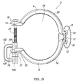
- G-Clamp 2 is illustrated with separation means in the form of a clip 102 which acts to maintain ends 18, 20 of members 4, 6 in an unclamped position More particularly, clip 102 has a first end 104 clipped to a portion of bolt 22 between ends 18, 20, and preferably abutting inner surface of end 20, and a second end 106 abutting against nut 21. The nut 21 also abuts against outer surface of end 20.
- a U-shaped linking arm 108 is provided between ends 104, 106. Arm 108 is typically U-shaped so as to avoid any obstruction or interference with end 26 of member 6 but it could be any suitable shape.
Landscapes
- Engineering & Computer Science (AREA)
- General Engineering & Computer Science (AREA)
- Mechanical Engineering (AREA)
- Clamps And Clips (AREA)
- Jigs For Machine Tools (AREA)
- Electrical Discharge Machining, Electrochemical Machining, And Combined Machining (AREA)
Abstract
Description
- This invention relates to a clamping device for clamping two or more articles together.
- Although the following description refers almost exclusively to a clamping device in the form of a G-clamp for clamping a turbo charger of a motor vehicle to an exhaust pipe, it will be appreciated by persons skilled in the art that the present invention can be used to clamp any two or more articles together, and particularly but not necessarily exclusively, to clamp two or more flanged articles together.
- Currently, in order to fit a turbo charger to an exhaust pipe on a motor vehicle, a G-clamp is used comprising two semi-circular segments hinged together at a first end to allow the segments to pivot relative to each other between clamped and unclamped positions. The second or free ends of the segments can be engaged together via a nut and bolt to maintain the segments in the clamped position. In use, the flanged portions of the turbo charger and the exhaust pipe are brought into abutting relationship and held together via a first user in a required position. A second user locates the members of the G-clamp around the flanged portions and moves the engagement nut and bolt into engagement position to clamp the G-clamp around the flanged portions.
- A problem with the above method is that it typically requires two people to use the clamp, thereby being a labour intensive and expensive process to undertake.
- It is therefore an aim of the present invention to provide a clamping device which is easy to use and which in one aspect can be fitted by a single user.
- It is a further aim of the present invention to provide a method of using a clamping device.
- According to a first aspect of the present invention there is provided a clamping device for clamping two or more articles together, said clamping device including two or more members movable between an unclamped position and a clamped position, characterised in that resilient biasing means are provided on or associated with said clamping device to bias the two or more members to said clamped position in use.
- The biasing means allows the device to automatically move to a clamped position when fitted, thereby removing the requirement of a user manually moving the same to a clamped position. This makes the clamping device easier and quicker to use and can be fitted by a single user.
- In the unclamped position, one or more ends of a member are typically located a spaced distance apart from an adjacent member. In the clamped position, the one or more ends of said member are moved into engagement with, into abutting relationship with and/or moved such that the spaced distance is reduced with respect to an adjacent member.
- Movement of the members from the unclamped position to the clamped position typically reduces the diameter or dimensions defined by or within said members, thereby allowing clamping of two or more articles located within said clamping members. For example, at least one aperture can be defined by or between said members and the dimensions of said aperture are reduced when said device moves from said unclamped to said clamped position.
- In one embodiment the two or more members are hingedly or pivotably connected to each other, directly or indirectly, to allow rotation or pivoting of said members between said clamped and unclamped positions. For example, ends of the members can be movably mounted via a link plate. The link plate typically includes a plate including one or more apertures defined therein, such as an aperture defined at each end of the plate. The ends of the members are typically movably mounted in the apertures.
- In one embodiment two or more members are connected together by connection means and said connection means are movable to allow the members to move between said clamped and unclamped positions.
- The resilient biasing means can include any or any combination of one or more springs, sprung material, elastic, rubber and/or the like.
- Preferably the resilient biasing means are provided over, across or are associated with the connection point or points connecting the two or more members together, such as for example, over the hinge joining the two members together. The biasing means typically provide a compressive force over or across the connection means of the members biasing the members together.
- Preferably engagement means can be provided to maintain the members in at least a clamped position. The engagement means can be associated with the connection means, link plate and/or hinge or pivot connection but preferably the engagement means are associated with free ends of the members, and preferably opposite to the hinge or pivot connection. The engagement means can, in one embodiment be used to maintain the members in an unclamped position.
- The engagement means can include any or any combination of one or more clips, ties, welding, adhesive, nut and bolt, screw and/or the like.
- In one embodiment separation means can be provided to maintain said members in an unclamped position. Preferably the separation means are provided between the free ends of the two or more members. The separation means are typically detachably attached to the device or to one or more members of the device, such that removal of said separation means moves the members from an unclamped position to a clamped position under the bias of the resilient biasing means. Thus, the separation means are of such a form so as to provide sufficient force to overcome the bias of the resilient biasing means when fitted to the device.
- The separation means can include any or any combination of one or more screws, clips, bolts and/or the like.
- The resilient biasing means can be attached to the device via any suitable means, such as adhesive, welding, one or more screws, nut & bolt, inter-engaging means and/or the like. In one embodiment the resilient biasing means are detachably attached to said device.
- Preferably the clamping device is provided with mounting means for allowing the device to be mounted in, on or with respect to a required position or surface in use. The device is typically mounted prior to movement of the device from the unclamped to the clamped position.
- The mounting means typically protrudes outwardly from a surface of the device to allow a substantial part of the device to be mounted a spaced distance from a suitable surface or article.
- In one embodiment the mounting means is in the form of or includes a plate, such as a weld plate, to allow the device to be welded in a required location prior to actuation of the clamping device.
- The mounting means can be attached to one or more of the members, to the resilient biasing means, to connection means connecting the members together and/or the like.
- Preferably the clamping device is in the form of a G-clamp with two substantially semi-circular members, the two members being preferably hingedly connected together.
- According to a second aspect of the present invention there is provided a clamping device for clamping two or more articles together, said clamping device including two or more members movable between an unclamped position and a clamped position, characterised in that mounting means are provided on or associated with said clamping device to allow the device to be mounted on or relative to one or more of said articles prior to actuation of said clamping device.
- The mounting means allows the clamping device to be mounted to a suitable surface in the locality in which it is to be fitted prior to moving the clamping device between unclamped and clamped positions. As such, a user can mount the device and then have their hands free to actuate the clamping device and/or move the two articles together with respect to the clamping device to a required position without the need to have an additional user to help fit the same.
- The mounting means and resilient biasing means can be used independently of each other or in combination with each other to provide an improved clamping device.
- According to a further aspect of the present invention there is provided a method of using a clamping device for clamping two or more articles together, said clamping device including two or more members movable between an unclamped position and a clamped position and said method including the steps of locating the device around said articles being clamped and allowing said members to move from said unclamped position to said clamped position under the resilient biasing force of resilient biasing means provided on or associated with said clamping device.
- According to a yet further aspect of the present invention there is provided a method of using a clamping device for clamping two or more articles together, said clamping device including two or more members movable between an unclamped position and a clamped position and said method including the steps of mounting the device to a surface on or relative to one of the articles to be clamped using mounting means provided on or associated with said clamping device prior to actuation of said clamping device.
- Embodiments of the present invention will now be described with reference to the accompanying figures, wherein:
- Figure 1 is an enlarged plan view of a clamping device according to the present invention;
- Figures 2a-2g illustrate a side view, plan view, end view, perspective view, detailed view of the engagement means, detailed view of the hinge and cross sectional view taken along line X-X in figure 2b of the device in figure 1 respectively; and
- Figure 3 is a plan view of a clamping device with separation means according to one embodiment of the present invention.
- Referring to figures 1-2g, there is illustrated a clamping device in the form of a G-
clamp 2 having first and second members orsegments - First and
second members ends link member 12 having slots 14 defined therein for location ofends free ends hook 16 to prevent removal of the same fromlink member 12. As such,members link member 12 between clamped and unclamped positions. - Ends 18, 20 of
members ends nut 21 andbolt 22 which passes through an aperture defined inend plates ends end plates aperture 28 defined betweenmembers bolt members members - In the unclamped position,
ends aperture 28 are relatively large, thereby allowingmembers ends ends aperture 28 are reduced, thereby providing a clamping force on the two flanged articles around which the device is placed. - In the illustrated example,
members circular aperture 28 between the same.End plates aperture 28 and are substantially perpendicular to the semi-circular member end to which they communicate with, are joined to or are integral with. However,members - In accordance with a first aspect of the present invention, resilient biasing means in the form of sprung
closure clip 30 is joined tomembers clip 30 hasend portions members middle portion 36 is provided betweenend portions hinge link member 12.Clip 30biases members - Separation means can be located between
end plates members - In accordance with a second aspect of the present invention there is provided mounting means in the form of a
welding plate 38. Weldingplate 38 protrudes outwardly of the device to allow the device to be welded relative to one or both of the articles to be joined together in use. By welding the device prior to moving the clamping device between the unclamped and clamped positions, the device can be located in a required position without a person having to hold the same. This frees up a user's hand to move the two articles together into a clamped position without requiring an additional user to help fit the clamp. - The welding plate can be provided in any suitable, size, shape, design and can be provided in any suitable position on the device. In the illustrated example, welding
plate 38 is joined to linkplate 12 and includes afirst connection portion 40, anintermediate portion 42 and asecond connection portion 44 which is welded to a required surface in use.Intermediate portion 42 positions second connection portion 44 a spaced distance apart fromfirst connection portion 40 and is of such a size and angle to allow the device to be located at a suitable angle and distance from the surface to whichsecond connection portion 44 is to be joined in use. - The members can be formed or any suitable material and can be of any shape to define an aperture of any suitable size or shape. The resilient biasing means can also be of any suitable size, shape and design and in the illustrated example of the present invention is formed of sprung stainless steel so as to withstand relatively high temperatures associated with the application of joining a turbo charger of a motor vehicle to an exhaust pipe.
- Thus, in use of the device, a user welds the
weld plate 38 to a suitable surface and moves the device to the unclamped position. The user brings the two flanged articles together in a required position and/or orientation, such that the parts of the articles to be joined are located through the aperture defined by the clamping members. Whilst holding the articles in place, the user removes the separation means holding the members in an unclamped position and the bias of the resilient biasing means moves the members to a clamped position around the articles. - Referring to figure 3, G-
Clamp 2 is illustrated with separation means in the form of aclip 102 which acts to maintain ends 18, 20 ofmembers clip 102 has afirst end 104 clipped to a portion ofbolt 22 between ends 18, 20, and preferably abutting inner surface ofend 20, and asecond end 106 abutting againstnut 21. Thenut 21 also abuts against outer surface ofend 20. AU-shaped linking arm 108 is provided betweenends Arm 108 is typically U-shaped so as to avoid any obstruction or interference withend 26 ofmember 6 but it could be any suitable shape. - With
clip 102 in place,free end 20 ofmember 6 is maintained a spaced distance apart fromfree end 18 ofmember 4 since the clip acts against the resilient bias ofclosure clip 30. In addition,nut 21 is maintained in position on the free end ofbolt 22 and the engagement means are in an unclamped position. Removal ofclip 102 allows free ends 18, 20 to move towards each other automatically under the bias ofclosure clip 30. This removes the requirement for a user to have a free hand to manually move the ends 18, 20 together, thereby allowing the user to maintain the items being clamped together in a suitable position during the clamping process.
Claims (27)
- A clamping device for clamping two or more articles together, said clamping device including two or more members movable between an unclamped position and a clamped position, characterised in that resilient biasing means are provided on or associated with said clamping device to bias the two or more members to said clamped position in use.
- A clamping device according to claim 1 characterised in that in the unclamped position, one or ends of a member are a spaced distance apart from one or more ends of an adjacent member.
- A clamping device according to claim 2 characterised in that in the clamped position, the ends of the members are moved into engagement, into abutting relationship and/or moved such that a spaced distance between the ends is reduced compared to in the unclamped position.
- A clamping device according to claim 1 characterised in that at least one aperture is defined by or between the two or more members and the dimensions of said aperture are reduced as the device is moved from the unclamped position to the clamped position.
- A clamping device according to claim 1 characterised in that the two or more members are hingedly or pivotably connected, either directly or indirectly to each other, to allow rotation or pivoting of said members between said clamped and unclamped positions.
- A clamping device according to claim 1 characterised in that the two or more members are movably mounted to each other via a link plate.
- A clamping device according to claim 6 characterised in that the link plate has one or more apertures defined therein and each end of each member is movably mounted in said one or more apertures.
- A clamping device according to claim 1 characterised in that the two or more members are connected together by connection means and said connection means are movable to allow the members to move between said clamped and unclamped position.
- A clamping device according to claim 1 characterised in that the resilient biasing means includes any or any combination of one or more springs, sprung material, elastic or rubber.
- A clamping device according to claim 1 characterised in that the resilient biasing means are provided over, across or are associated with the connection point or points connecting the two or more members together.
- A clamping device according to claim 1 characterised in that engagement means are provided to maintain the members in at least a clamped position.
- A clamping device according to claim 11 characterised in that the engagement means are associated with the free ends of the members.
- A clamping device according to claim 11 characterised in that the engagement means includes any or any combination of one or more clips, ties, welding, adhesive, nut and bolt and/or screw.
- A clamping device according to claim 1 characterised in that separation means are provided to maintain said two or more members in an unclamped position.
- A clamping device according to claim 14 characterised in that the separation means are located between the free ends of said members.
- A clamping device according to claim 14 characterised in that the separation means are detachably attached to one or more of said members.
- A clamping device according to claim 14 characterised in that the separation means includes any or any combination of one or more screws, clips or bolts.
- A clamping device according to claim 1 characterised in that the resilient biasing means are attached to the device via welding, adhesive, one or more screws, nut and bolt and/or inter-engaging means.
- A clamping device according to claim 1 characterised in that mounting means are provided to allow the device to be mounted in a required position on or with respect to an article or surface in use.
- A clamping device according to claim 19 characterised in that the mounting means protrude outwardly from a surface of the device.
- A clamping device according to claim 20 characterised in that the mounting means is in the form of a plate.
- A clamping device according to claim 20 characterised in that the amounting means includes first and second connection portions with an intermediate portion located therebetween.
- A clamping device according to claim 1 characterised in that the device is in the form of a G-Clamp with two substantially semi-circular members.
- A clamping device for clamping two or more articles together, said clamping device including two or more members movable between an unclamped position and a clamped position, characterised in that mounting means are provided on or associated with said clamping device to allow the device to be mounted on or relative to one or more of said articles prior to actuation of said clamping device.
- A clamping device according to any preceding claim wherein at least one of the two or more articles is provided with a flange on which said device is mounted in use.
- A method of using a clamping device for clamping two or more articles together, said clamping device including two or more members movable between an unclamped position and a clamped position and said method including the steps of locating the device around said articles being clamped and allowing said members to move from said unclamped position to said clamped position under the resilient biasing force of resilient biasing means provided on or associated with said clamping device.
- A method of using a clamping device for clamping two or more articles together, said clamping device including two or more members movable between an unclamped position and a clamped position and said method including the steps of mounting the device to a surface on or relative to one of the articles to be clamped using mounting means provided on or associated with said clamping device prior to actuation of said clamping device.
Applications Claiming Priority (1)
| Application Number | Priority Date | Filing Date | Title |
|---|---|---|---|
| GBGB0606299.6A GB0606299D0 (en) | 2006-03-30 | 2006-03-30 | Clamping device |
Publications (3)
| Publication Number | Publication Date |
|---|---|
| EP1840439A2 true EP1840439A2 (en) | 2007-10-03 |
| EP1840439A3 EP1840439A3 (en) | 2007-11-28 |
| EP1840439B1 EP1840439B1 (en) | 2010-06-16 |
Family
ID=36424819
Family Applications (1)
| Application Number | Title | Priority Date | Filing Date |
|---|---|---|---|
| EP07251043A Active EP1840439B1 (en) | 2006-03-30 | 2007-03-14 | Clamping device |
Country Status (4)
| Country | Link |
|---|---|
| EP (1) | EP1840439B1 (en) |
| AT (1) | ATE471479T1 (en) |
| DE (1) | DE602007007138D1 (en) |
| GB (1) | GB0606299D0 (en) |
Cited By (17)
| Publication number | Priority date | Publication date | Assignee | Title |
|---|---|---|---|---|
| EP2325535A1 (en) | 2009-11-19 | 2011-05-25 | Alteco S.r.l. | Coupling for metal containers and/or pressurised pipes |
| KR101215321B1 (en) | 2009-09-03 | 2012-12-26 | 노르마 저머니 게엠베하 | Profile clamp |
| EP2674656A1 (en) * | 2012-06-14 | 2013-12-18 | NORMA Germany GmbH | Profile clamp |
| FR3001787A1 (en) * | 2013-02-07 | 2014-08-08 | Norma Germany Gmbh | PROFILE CLAMPING COLLAR, WITH A PREPOSITIONING SYSTEM |
| US9004545B2 (en) | 2011-03-07 | 2015-04-14 | Nordson Corporation | Clamp for sanitary fitting |
| WO2016005442A1 (en) * | 2014-07-09 | 2016-01-14 | Jaguar Land Rover Limited | Improved fastening device |
| WO2016034820A1 (en) | 2014-09-04 | 2016-03-10 | Etablissements Caillau | System for coupling two tubes |
| DE102014113165A1 (en) * | 2014-09-12 | 2016-03-17 | Ihi Charging Systems International Gmbh | turbocharger |
| WO2017149104A1 (en) * | 2016-03-04 | 2017-09-08 | Norma Germany Gmbh | Pre-positioner for a profiled clamp and connecting arrangement having such a pre-positioner |
| US10458579B2 (en) | 2016-05-16 | 2019-10-29 | Victaulic Company | Sprung coupling |
| US10533688B2 (en) | 2016-05-16 | 2020-01-14 | Victaulic Company | Coupling having tabbed retainer |
| US10578234B2 (en) | 2013-05-02 | 2020-03-03 | Victaulic Company | Coupling having arcuate stiffness ribs |
| US10605394B2 (en) | 2016-05-16 | 2020-03-31 | Victaulic Company | Fitting having tabbed retainer and observation apertures |
| US11060639B2 (en) | 2015-12-28 | 2021-07-13 | Victaulic Company | Adapter coupling |
| US11448346B2 (en) | 2018-09-28 | 2022-09-20 | ASC Engineered Solutions, LLC | Pipe coupling |
| US11781683B2 (en) | 2019-11-15 | 2023-10-10 | Victaulic Company | Shrouded coupling |
| US11821548B2 (en) | 2016-12-14 | 2023-11-21 | ASC Engineered Solutions, LLC | Pipe couplings |
Families Citing this family (2)
| Publication number | Priority date | Publication date | Assignee | Title |
|---|---|---|---|---|
| USD695100S1 (en) | 2011-10-18 | 2013-12-10 | Nordson Corporation | Clamp for a sanitary fitting |
| FR3057047B1 (en) * | 2016-10-04 | 2019-05-10 | Etablissements Caillau | CONTROLLED ANGULAR POSITION CLAMPING SYSTEM FOR CONNECTING TWO TUBES |
Citations (5)
| Publication number | Priority date | Publication date | Assignee | Title |
|---|---|---|---|---|
| US4657284A (en) | 1985-03-08 | 1987-04-14 | Commissariat A L'energie Atomique | Remotely manipulatable clamp |
| US4730850A (en) | 1985-05-11 | 1988-03-15 | Niigata Engineering Co., Ltd. | Quick release coupling device |
| US6030006A (en) | 1998-02-23 | 2000-02-29 | Lin; Peter | Spring biased clamping device for flanged connections |
| US6056332A (en) | 1999-03-09 | 2000-05-02 | Foster; Clark | Clamping apparatus |
| US20030116967A1 (en) | 2001-12-20 | 2003-06-26 | Kornau Joshua R. | Self-aligning coupling assembly |
Family Cites Families (2)
| Publication number | Priority date | Publication date | Assignee | Title |
|---|---|---|---|---|
| JPS58119927A (en) * | 1982-01-12 | 1983-07-16 | Mitsubishi Heavy Ind Ltd | Fixed flange joint and its manufacturing method |
| FR2697893B1 (en) * | 1992-11-06 | 1995-01-27 | Goavec Sa | Collar for the removable connection of two pipes. |
-
2006
- 2006-03-30 GB GBGB0606299.6A patent/GB0606299D0/en not_active Ceased
-
2007
- 2007-03-14 AT AT07251043T patent/ATE471479T1/en not_active IP Right Cessation
- 2007-03-14 EP EP07251043A patent/EP1840439B1/en active Active
- 2007-03-14 DE DE602007007138T patent/DE602007007138D1/en active Active
Patent Citations (5)
| Publication number | Priority date | Publication date | Assignee | Title |
|---|---|---|---|---|
| US4657284A (en) | 1985-03-08 | 1987-04-14 | Commissariat A L'energie Atomique | Remotely manipulatable clamp |
| US4730850A (en) | 1985-05-11 | 1988-03-15 | Niigata Engineering Co., Ltd. | Quick release coupling device |
| US6030006A (en) | 1998-02-23 | 2000-02-29 | Lin; Peter | Spring biased clamping device for flanged connections |
| US6056332A (en) | 1999-03-09 | 2000-05-02 | Foster; Clark | Clamping apparatus |
| US20030116967A1 (en) | 2001-12-20 | 2003-06-26 | Kornau Joshua R. | Self-aligning coupling assembly |
Cited By (41)
| Publication number | Priority date | Publication date | Assignee | Title |
|---|---|---|---|---|
| KR101215321B1 (en) | 2009-09-03 | 2012-12-26 | 노르마 저머니 게엠베하 | Profile clamp |
| EP2325535A1 (en) | 2009-11-19 | 2011-05-25 | Alteco S.r.l. | Coupling for metal containers and/or pressurised pipes |
| US9004545B2 (en) | 2011-03-07 | 2015-04-14 | Nordson Corporation | Clamp for sanitary fitting |
| EP2674656A1 (en) * | 2012-06-14 | 2013-12-18 | NORMA Germany GmbH | Profile clamp |
| CN103511770A (en) * | 2012-06-14 | 2014-01-15 | 诺马德国有限责任公司 | Profile clamp |
| CN103511770B (en) * | 2012-06-14 | 2016-09-14 | 诺马德国有限责任公司 | Profile clamp |
| US9151422B2 (en) | 2012-06-14 | 2015-10-06 | Norma Germany Gmbh | Profile clamp |
| KR101505972B1 (en) * | 2012-06-14 | 2015-03-25 | 노르마 저머니 게엠베하 | Profile clamp |
| FR3001787A1 (en) * | 2013-02-07 | 2014-08-08 | Norma Germany Gmbh | PROFILE CLAMPING COLLAR, WITH A PREPOSITIONING SYSTEM |
| CN103982497A (en) * | 2013-02-07 | 2014-08-13 | 诺马德国有限责任公司 | Profile clamp with pre-positioner |
| EP2765342A1 (en) * | 2013-02-07 | 2014-08-13 | NORMA Germany GmbH | Profiled clamp with pre-positioner |
| CN103982497B (en) * | 2013-02-07 | 2017-06-20 | 诺马德国有限责任公司 | Profile clamp with pre-determined bit device |
| US9494265B2 (en) | 2013-02-07 | 2016-11-15 | Norma Germany Gmbh | Profile clamp with pre-positioner |
| US12129941B2 (en) | 2013-05-02 | 2024-10-29 | Victaulic Company | Coupling having arcuate stiffness ribs |
| US10578234B2 (en) | 2013-05-02 | 2020-03-03 | Victaulic Company | Coupling having arcuate stiffness ribs |
| WO2016005442A1 (en) * | 2014-07-09 | 2016-01-14 | Jaguar Land Rover Limited | Improved fastening device |
| RU2684052C2 (en) * | 2014-09-04 | 2019-04-03 | Этаблиссман Кайо | System for coupling two tubes |
| WO2016034820A1 (en) | 2014-09-04 | 2016-03-10 | Etablissements Caillau | System for coupling two tubes |
| US10563799B2 (en) | 2014-09-04 | 2020-02-18 | Etablissements Caillau | System for coupling two tubes |
| FR3025581A1 (en) * | 2014-09-04 | 2016-03-11 | Caillau Ets | SYSTEM FOR CONNECTING TWO TUBES |
| DE102014113165A1 (en) * | 2014-09-12 | 2016-03-17 | Ihi Charging Systems International Gmbh | turbocharger |
| US11060639B2 (en) | 2015-12-28 | 2021-07-13 | Victaulic Company | Adapter coupling |
| US12486929B2 (en) | 2015-12-28 | 2025-12-02 | Victaulic Company | Adapter coupling |
| US11725756B2 (en) | 2015-12-28 | 2023-08-15 | Victaulic Company | Adapter coupling |
| KR20180115304A (en) * | 2016-03-04 | 2018-10-22 | 노르마 저머니 게엠베하 | Connection device with pre-positioner for pre-profiled clamp and pre-positioner |
| JP2019508643A (en) * | 2016-03-04 | 2019-03-28 | ノルマ ジャーマニー ゲーエムベーハー | Prepositioner for profiled clamps and interlocking arrangement comprising such a prepositioner |
| US11156315B2 (en) | 2016-03-04 | 2021-10-26 | Norma Germany Gmbh | Pre-positioner for a profiled clamp and connecting arrangement having such a pre-positioner |
| WO2017149104A1 (en) * | 2016-03-04 | 2017-09-08 | Norma Germany Gmbh | Pre-positioner for a profiled clamp and connecting arrangement having such a pre-positioner |
| US11125369B2 (en) | 2016-05-16 | 2021-09-21 | Victaulic Company | Coupling having tabbed retainer |
| US10731780B2 (en) | 2016-05-16 | 2020-08-04 | Victaulic Company | Sprung coupling |
| US10627025B2 (en) | 2016-05-16 | 2020-04-21 | Victaulic Company | Sprung coupling |
| US10605394B2 (en) | 2016-05-16 | 2020-03-31 | Victaulic Company | Fitting having tabbed retainer and observation apertures |
| US11821546B2 (en) | 2016-05-16 | 2023-11-21 | Victaulic Company | Sprung coupling |
| US11859737B2 (en) | 2016-05-16 | 2024-01-02 | Victaulic Company | Captured element coupling |
| US11879571B2 (en) | 2016-05-16 | 2024-01-23 | Victaulic Company | Captured element coupling |
| US10533688B2 (en) | 2016-05-16 | 2020-01-14 | Victaulic Company | Coupling having tabbed retainer |
| US10458579B2 (en) | 2016-05-16 | 2019-10-29 | Victaulic Company | Sprung coupling |
| US11821548B2 (en) | 2016-12-14 | 2023-11-21 | ASC Engineered Solutions, LLC | Pipe couplings |
| US11448346B2 (en) | 2018-09-28 | 2022-09-20 | ASC Engineered Solutions, LLC | Pipe coupling |
| US11828392B2 (en) | 2018-09-28 | 2023-11-28 | ASC Engineered Solutions, LLC | Hooked pipe coupling segment |
| US11781683B2 (en) | 2019-11-15 | 2023-10-10 | Victaulic Company | Shrouded coupling |
Also Published As
| Publication number | Publication date |
|---|---|
| DE602007007138D1 (en) | 2010-07-29 |
| EP1840439A3 (en) | 2007-11-28 |
| ATE471479T1 (en) | 2010-07-15 |
| GB0606299D0 (en) | 2006-05-10 |
| EP1840439B1 (en) | 2010-06-16 |
Similar Documents
| Publication | Publication Date | Title |
|---|---|---|
| EP1840439A2 (en) | Clamping device | |
| US20140054357A1 (en) | Welding Fixture Clamp | |
| US6173947B1 (en) | Automotive bumper stand | |
| AU2007200151B2 (en) | Retention linkage for vehicle exhaust systems | |
| EP1518784A3 (en) | Automotive vehicle framing system | |
| CN1707125A (en) | Clip | |
| EP1764291A3 (en) | Automotive vehicle framing system | |
| WO1998058772A1 (en) | Portable adjustable chain type clamping device | |
| CN205129670U (en) | A can dismantle system for fixing two parts | |
| US5895035A (en) | Pipe fitting apparatus | |
| US7373862B2 (en) | Clamp device | |
| US7226047B1 (en) | Welder's pipe clamp | |
| US20080226427A1 (en) | Apparatus for accurately positioning and supporting modular tooling | |
| KR20160075430A (en) | Curved pipe fixing device which has tilted 3 point fixture | |
| JP2002511346A (en) | Tightening device for holding body parts | |
| CN115178947B (en) | Overturning positioning device and welding positioning mechanism | |
| US7421822B1 (en) | Stabilizing support for an animal trap | |
| CA2624261A1 (en) | A multipurpose support for attachments mountable to the tow hitch of a vehicle | |
| US20100237551A1 (en) | Connector | |
| JP3737891B2 (en) | Automotive exhaust pipe connection jig | |
| EP0351019A1 (en) | Repair clamp and closing means for use in said repair clamp | |
| CN208963207U (en) | Tail-gate fixing tool | |
| JPH05157188A (en) | Clamp for electrofusion joint | |
| CN216063858U (en) | A door isolation fixture for car application | |
| JP3356036B2 (en) | Work holding device |
Legal Events
| Date | Code | Title | Description |
|---|---|---|---|
| PUAI | Public reference made under article 153(3) epc to a published international application that has entered the european phase |
Free format text: ORIGINAL CODE: 0009012 |
|
| AK | Designated contracting states |
Kind code of ref document: A2 Designated state(s): AT BE BG CH CY CZ DE DK EE ES FI FR GB GR HU IE IS IT LI LT LU LV MC MT NL PL PT RO SE SI SK TR |
|
| AX | Request for extension of the european patent |
Extension state: AL BA HR MK YU |
|
| PUAL | Search report despatched |
Free format text: ORIGINAL CODE: 0009013 |
|
| AK | Designated contracting states |
Kind code of ref document: A3 Designated state(s): AT BE BG CH CY CZ DE DK EE ES FI FR GB GR HU IE IS IT LI LT LU LV MC MT NL PL PT RO SE SI SK TR |
|
| AX | Request for extension of the european patent |
Extension state: AL BA HR MK YU |
|
| 17P | Request for examination filed |
Effective date: 20080528 |
|
| AKX | Designation fees paid |
Designated state(s): AT BE BG CH CY CZ DE DK EE ES FI FR GB GR HU IE IS IT LI LT LU LV MC MT NL PL PT RO SE SI SK TR |
|
| 17Q | First examination report despatched |
Effective date: 20081212 |
|
| GRAP | Despatch of communication of intention to grant a patent |
Free format text: ORIGINAL CODE: EPIDOSNIGR1 |
|
| GRAS | Grant fee paid |
Free format text: ORIGINAL CODE: EPIDOSNIGR3 |
|
| GRAA | (expected) grant |
Free format text: ORIGINAL CODE: 0009210 |
|
| AK | Designated contracting states |
Kind code of ref document: B1 Designated state(s): AT BE BG CH CY CZ DE DK EE ES FI FR GB GR HU IE IS IT LI LT LU LV MC MT NL PL PT RO SE SI SK TR |
|
| REG | Reference to a national code |
Ref country code: CH Ref legal event code: EP |
|
| REG | Reference to a national code |
Ref country code: IE Ref legal event code: FG4D |
|
| REF | Corresponds to: |
Ref document number: 602007007138 Country of ref document: DE Date of ref document: 20100729 Kind code of ref document: P |
|
| REG | Reference to a national code |
Ref country code: NL Ref legal event code: VDEP Effective date: 20100616 |
|
| PG25 | Lapsed in a contracting state [announced via postgrant information from national office to epo] |
Ref country code: LT Free format text: LAPSE BECAUSE OF FAILURE TO SUBMIT A TRANSLATION OF THE DESCRIPTION OR TO PAY THE FEE WITHIN THE PRESCRIBED TIME-LIMIT Effective date: 20100616 Ref country code: SE Free format text: LAPSE BECAUSE OF FAILURE TO SUBMIT A TRANSLATION OF THE DESCRIPTION OR TO PAY THE FEE WITHIN THE PRESCRIBED TIME-LIMIT Effective date: 20100616 |
|
| LTIE | Lt: invalidation of european patent or patent extension |
Effective date: 20100616 |
|
| PG25 | Lapsed in a contracting state [announced via postgrant information from national office to epo] |
Ref country code: SI Free format text: LAPSE BECAUSE OF FAILURE TO SUBMIT A TRANSLATION OF THE DESCRIPTION OR TO PAY THE FEE WITHIN THE PRESCRIBED TIME-LIMIT Effective date: 20100616 Ref country code: AT Free format text: LAPSE BECAUSE OF FAILURE TO SUBMIT A TRANSLATION OF THE DESCRIPTION OR TO PAY THE FEE WITHIN THE PRESCRIBED TIME-LIMIT Effective date: 20100616 Ref country code: FI Free format text: LAPSE BECAUSE OF FAILURE TO SUBMIT A TRANSLATION OF THE DESCRIPTION OR TO PAY THE FEE WITHIN THE PRESCRIBED TIME-LIMIT Effective date: 20100616 Ref country code: LV Free format text: LAPSE BECAUSE OF FAILURE TO SUBMIT A TRANSLATION OF THE DESCRIPTION OR TO PAY THE FEE WITHIN THE PRESCRIBED TIME-LIMIT Effective date: 20100616 |
|
| PG25 | Lapsed in a contracting state [announced via postgrant information from national office to epo] |
Ref country code: PL Free format text: LAPSE BECAUSE OF FAILURE TO SUBMIT A TRANSLATION OF THE DESCRIPTION OR TO PAY THE FEE WITHIN THE PRESCRIBED TIME-LIMIT Effective date: 20100616 Ref country code: CY Free format text: LAPSE BECAUSE OF FAILURE TO SUBMIT A TRANSLATION OF THE DESCRIPTION OR TO PAY THE FEE WITHIN THE PRESCRIBED TIME-LIMIT Effective date: 20100616 |
|
| PG25 | Lapsed in a contracting state [announced via postgrant information from national office to epo] |
Ref country code: EE Free format text: LAPSE BECAUSE OF FAILURE TO SUBMIT A TRANSLATION OF THE DESCRIPTION OR TO PAY THE FEE WITHIN THE PRESCRIBED TIME-LIMIT Effective date: 20100616 Ref country code: NL Free format text: LAPSE BECAUSE OF FAILURE TO SUBMIT A TRANSLATION OF THE DESCRIPTION OR TO PAY THE FEE WITHIN THE PRESCRIBED TIME-LIMIT Effective date: 20100616 |
|
| PG25 | Lapsed in a contracting state [announced via postgrant information from national office to epo] |
Ref country code: SK Free format text: LAPSE BECAUSE OF FAILURE TO SUBMIT A TRANSLATION OF THE DESCRIPTION OR TO PAY THE FEE WITHIN THE PRESCRIBED TIME-LIMIT Effective date: 20100616 Ref country code: BE Free format text: LAPSE BECAUSE OF FAILURE TO SUBMIT A TRANSLATION OF THE DESCRIPTION OR TO PAY THE FEE WITHIN THE PRESCRIBED TIME-LIMIT Effective date: 20100616 Ref country code: CZ Free format text: LAPSE BECAUSE OF FAILURE TO SUBMIT A TRANSLATION OF THE DESCRIPTION OR TO PAY THE FEE WITHIN THE PRESCRIBED TIME-LIMIT Effective date: 20100616 Ref country code: IS Free format text: LAPSE BECAUSE OF FAILURE TO SUBMIT A TRANSLATION OF THE DESCRIPTION OR TO PAY THE FEE WITHIN THE PRESCRIBED TIME-LIMIT Effective date: 20101016 Ref country code: PT Free format text: LAPSE BECAUSE OF FAILURE TO SUBMIT A TRANSLATION OF THE DESCRIPTION OR TO PAY THE FEE WITHIN THE PRESCRIBED TIME-LIMIT Effective date: 20101018 Ref country code: RO Free format text: LAPSE BECAUSE OF FAILURE TO SUBMIT A TRANSLATION OF THE DESCRIPTION OR TO PAY THE FEE WITHIN THE PRESCRIBED TIME-LIMIT Effective date: 20100616 |
|
| PG25 | Lapsed in a contracting state [announced via postgrant information from national office to epo] |
Ref country code: IT Free format text: LAPSE BECAUSE OF FAILURE TO SUBMIT A TRANSLATION OF THE DESCRIPTION OR TO PAY THE FEE WITHIN THE PRESCRIBED TIME-LIMIT Effective date: 20100616 |
|
| PLBE | No opposition filed within time limit |
Free format text: ORIGINAL CODE: 0009261 |
|
| STAA | Information on the status of an ep patent application or granted ep patent |
Free format text: STATUS: NO OPPOSITION FILED WITHIN TIME LIMIT |
|
| PG25 | Lapsed in a contracting state [announced via postgrant information from national office to epo] |
Ref country code: DK Free format text: LAPSE BECAUSE OF FAILURE TO SUBMIT A TRANSLATION OF THE DESCRIPTION OR TO PAY THE FEE WITHIN THE PRESCRIBED TIME-LIMIT Effective date: 20100616 Ref country code: GR Free format text: LAPSE BECAUSE OF FAILURE TO SUBMIT A TRANSLATION OF THE DESCRIPTION OR TO PAY THE FEE WITHIN THE PRESCRIBED TIME-LIMIT Effective date: 20100917 |
|
| 26N | No opposition filed |
Effective date: 20110317 |
|
| REG | Reference to a national code |
Ref country code: DE Ref legal event code: R097 Ref document number: 602007007138 Country of ref document: DE Effective date: 20110316 |
|
| PG25 | Lapsed in a contracting state [announced via postgrant information from national office to epo] |
Ref country code: MC Free format text: LAPSE BECAUSE OF NON-PAYMENT OF DUE FEES Effective date: 20110331 |
|
| REG | Reference to a national code |
Ref country code: CH Ref legal event code: PL |
|
| PG25 | Lapsed in a contracting state [announced via postgrant information from national office to epo] |
Ref country code: MT Free format text: LAPSE BECAUSE OF FAILURE TO SUBMIT A TRANSLATION OF THE DESCRIPTION OR TO PAY THE FEE WITHIN THE PRESCRIBED TIME-LIMIT Effective date: 20100616 |
|
| REG | Reference to a national code |
Ref country code: IE Ref legal event code: MM4A |
|
| PG25 | Lapsed in a contracting state [announced via postgrant information from national office to epo] |
Ref country code: IE Free format text: LAPSE BECAUSE OF NON-PAYMENT OF DUE FEES Effective date: 20110314 Ref country code: CH Free format text: LAPSE BECAUSE OF NON-PAYMENT OF DUE FEES Effective date: 20110331 Ref country code: LI Free format text: LAPSE BECAUSE OF NON-PAYMENT OF DUE FEES Effective date: 20110331 |
|
| PG25 | Lapsed in a contracting state [announced via postgrant information from national office to epo] |
Ref country code: LU Free format text: LAPSE BECAUSE OF NON-PAYMENT OF DUE FEES Effective date: 20110314 |
|
| PG25 | Lapsed in a contracting state [announced via postgrant information from national office to epo] |
Ref country code: BG Free format text: LAPSE BECAUSE OF FAILURE TO SUBMIT A TRANSLATION OF THE DESCRIPTION OR TO PAY THE FEE WITHIN THE PRESCRIBED TIME-LIMIT Effective date: 20100916 Ref country code: TR Free format text: LAPSE BECAUSE OF FAILURE TO SUBMIT A TRANSLATION OF THE DESCRIPTION OR TO PAY THE FEE WITHIN THE PRESCRIBED TIME-LIMIT Effective date: 20100616 |
|
| PG25 | Lapsed in a contracting state [announced via postgrant information from national office to epo] |
Ref country code: HU Free format text: LAPSE BECAUSE OF FAILURE TO SUBMIT A TRANSLATION OF THE DESCRIPTION OR TO PAY THE FEE WITHIN THE PRESCRIBED TIME-LIMIT Effective date: 20100616 Ref country code: ES Free format text: LAPSE BECAUSE OF FAILURE TO SUBMIT A TRANSLATION OF THE DESCRIPTION OR TO PAY THE FEE WITHIN THE PRESCRIBED TIME-LIMIT Effective date: 20100927 |
|
| REG | Reference to a national code |
Ref country code: FR Ref legal event code: PLFP Year of fee payment: 10 |
|
| REG | Reference to a national code |
Ref country code: FR Ref legal event code: PLFP Year of fee payment: 11 |
|
| REG | Reference to a national code |
Ref country code: FR Ref legal event code: PLFP Year of fee payment: 12 |
|
| P01 | Opt-out of the competence of the unified patent court (upc) registered |
Effective date: 20230403 |
|
| PGFP | Annual fee paid to national office [announced via postgrant information from national office to epo] |
Ref country code: DE Payment date: 20250219 Year of fee payment: 19 |
|
| PGFP | Annual fee paid to national office [announced via postgrant information from national office to epo] |
Ref country code: FR Payment date: 20250218 Year of fee payment: 19 |
|
| PGFP | Annual fee paid to national office [announced via postgrant information from national office to epo] |
Ref country code: GB Payment date: 20250218 Year of fee payment: 19 |