EP1840407A1 - Shock absorbers with mounting position protection - Google Patents
Shock absorbers with mounting position protection Download PDFInfo
- Publication number
- EP1840407A1 EP1840407A1 EP07005656A EP07005656A EP1840407A1 EP 1840407 A1 EP1840407 A1 EP 1840407A1 EP 07005656 A EP07005656 A EP 07005656A EP 07005656 A EP07005656 A EP 07005656A EP 1840407 A1 EP1840407 A1 EP 1840407A1
- Authority
- EP
- European Patent Office
- Prior art keywords
- shock absorber
- absorber according
- bearing
- end piece
- projection
- Prior art date
- Legal status (The legal status is an assumption and is not a legal conclusion. Google has not performed a legal analysis and makes no representation as to the accuracy of the status listed.)
- Granted
Links
- 239000006096 absorbing agent Substances 0.000 title claims abstract description 61
- 230000035939 shock Effects 0.000 title claims description 59
- 238000009434 installation Methods 0.000 claims description 34
- 238000007493 shaping process Methods 0.000 claims description 3
- 230000015572 biosynthetic process Effects 0.000 abstract 1
- 239000003921 oil Substances 0.000 description 8
- 238000000465 moulding Methods 0.000 description 5
- 230000004048 modification Effects 0.000 description 3
- 238000012986 modification Methods 0.000 description 3
- 230000006870 function Effects 0.000 description 2
- 238000010521 absorption reaction Methods 0.000 description 1
- 230000006978 adaptation Effects 0.000 description 1
- 230000002411 adverse Effects 0.000 description 1
- 230000002146 bilateral effect Effects 0.000 description 1
- 238000005516 engineering process Methods 0.000 description 1
- 230000002349 favourable effect Effects 0.000 description 1
- 239000010720 hydraulic oil Substances 0.000 description 1
- 238000007654 immersion Methods 0.000 description 1
- 230000003993 interaction Effects 0.000 description 1
- 230000001681 protective effect Effects 0.000 description 1
- 239000007787 solid Substances 0.000 description 1
Images


Classifications
-
- F—MECHANICAL ENGINEERING; LIGHTING; HEATING; WEAPONS; BLASTING
- F16—ENGINEERING ELEMENTS AND UNITS; GENERAL MEASURES FOR PRODUCING AND MAINTAINING EFFECTIVE FUNCTIONING OF MACHINES OR INSTALLATIONS; THERMAL INSULATION IN GENERAL
- F16F—SPRINGS; SHOCK-ABSORBERS; MEANS FOR DAMPING VIBRATION
- F16F9/00—Springs, vibration-dampers, shock-absorbers, or similarly-constructed movement-dampers using a fluid or the equivalent as damping medium
- F16F9/32—Details
- F16F9/54—Arrangements for attachment
-
- B—PERFORMING OPERATIONS; TRANSPORTING
- B60—VEHICLES IN GENERAL
- B60G—VEHICLE SUSPENSION ARRANGEMENTS
- B60G13/00—Resilient suspensions characterised by arrangement, location or type of vibration dampers
- B60G13/001—Arrangements for attachment of dampers
-
- F—MECHANICAL ENGINEERING; LIGHTING; HEATING; WEAPONS; BLASTING
- F16—ENGINEERING ELEMENTS AND UNITS; GENERAL MEASURES FOR PRODUCING AND MAINTAINING EFFECTIVE FUNCTIONING OF MACHINES OR INSTALLATIONS; THERMAL INSULATION IN GENERAL
- F16F—SPRINGS; SHOCK-ABSORBERS; MEANS FOR DAMPING VIBRATION
- F16F9/00—Springs, vibration-dampers, shock-absorbers, or similarly-constructed movement-dampers using a fluid or the equivalent as damping medium
- F16F9/06—Springs, vibration-dampers, shock-absorbers, or similarly-constructed movement-dampers using a fluid or the equivalent as damping medium using both gas and liquid
- F16F9/062—Bi-tubular units
-
- F—MECHANICAL ENGINEERING; LIGHTING; HEATING; WEAPONS; BLASTING
- F16—ENGINEERING ELEMENTS AND UNITS; GENERAL MEASURES FOR PRODUCING AND MAINTAINING EFFECTIVE FUNCTIONING OF MACHINES OR INSTALLATIONS; THERMAL INSULATION IN GENERAL
- F16F—SPRINGS; SHOCK-ABSORBERS; MEANS FOR DAMPING VIBRATION
- F16F9/00—Springs, vibration-dampers, shock-absorbers, or similarly-constructed movement-dampers using a fluid or the equivalent as damping medium
- F16F9/32—Details
- F16F9/3207—Constructional features
-
- F—MECHANICAL ENGINEERING; LIGHTING; HEATING; WEAPONS; BLASTING
- F16—ENGINEERING ELEMENTS AND UNITS; GENERAL MEASURES FOR PRODUCING AND MAINTAINING EFFECTIVE FUNCTIONING OF MACHINES OR INSTALLATIONS; THERMAL INSULATION IN GENERAL
- F16F—SPRINGS; SHOCK-ABSORBERS; MEANS FOR DAMPING VIBRATION
- F16F9/00—Springs, vibration-dampers, shock-absorbers, or similarly-constructed movement-dampers using a fluid or the equivalent as damping medium
- F16F9/32—Details
- F16F9/38—Covers for protection or appearance
-
- B—PERFORMING OPERATIONS; TRANSPORTING
- B60—VEHICLES IN GENERAL
- B60G—VEHICLE SUSPENSION ARRANGEMENTS
- B60G2204/00—Indexing codes related to suspensions per se or to auxiliary parts
- B60G2204/10—Mounting of suspension elements
- B60G2204/12—Mounting of springs or dampers
- B60G2204/128—Damper mount on vehicle body or chassis
-
- B—PERFORMING OPERATIONS; TRANSPORTING
- B60—VEHICLES IN GENERAL
- B60G—VEHICLE SUSPENSION ARRANGEMENTS
- B60G2204/00—Indexing codes related to suspensions per se or to auxiliary parts
- B60G2204/10—Mounting of suspension elements
- B60G2204/12—Mounting of springs or dampers
- B60G2204/129—Damper mount on wheel suspension or knuckle
Definitions
- the invention relates to a shock absorber having the features in the preamble of the main claim.
- Hydraulic shock absorbers with one or more pipes are sometimes mounted in prescribed installation positions.
- the installation position can not be detected reliably, for which reason corresponding labels are glued to the shock absorber for identification. Their subsequent attachment, however, is at risk of error.
- the invention solves this problem with the features in the main claim.
- the mechanical installation safety device on an end piece of the shock absorber simplifies the handling and correct installation of the shock absorber. It ensures the correct installation position and orientation of the shock absorber during assembly and prevents installation errors.
- the installation protection is provided by the manufacturer and can be created by a suitable design of the shock absorber and possibly the storage. On labels and the like other accessories can be omitted.
- the mechanical installation safety device is self-explanatory and requires no written instruction. Written installation instructions can be omitted.
- the mechanical installation protection is understandable for fitters internationally and without language problems.
- the mounting-plate fuse with the storage of the tail, preferably the bottom-side end piece or bottom piece of a damper tube, together.
- the installation position can be checked immediately and corrected if necessary immediately during bearing mounting.
- the mounting rail safety is arranged on the tail.
- the mechanical installation safety device is a fixed and unchangeable assignment between the fuse element and the shock absorber, so that inscription errors or other errors are excluded as in the prior art.
- the mechanical installation safety device can be designed in different ways. A deviating from the normal tail contour and e.g. asymmetric molded part gives an instantly recognizable and easily detectable installation orientation. It also prevents with appropriate design in connection with the storage that the shock absorber can be mounted in the wrong position at all.
- a securing element or molded part in the form of a protruding nose or rib is a particularly simple embodiment of the mounting device safety, which requires little effort and does not adversely affect the operation of the shock absorber.
- Such a mounting device fuse can also have an additional function and e.g. limit the swing angle of the shock absorber.
- a positional assignment of the installation-mounting safety device with respect to the flow-through openings of the bottom valve is recommended.
- This position assignment can be additionally secured by means of a rotary ball valve between bottom valve and valve seat on the end piece, in particular bottom piece.
- the invention relates to a hydraulic damper, in particular a shock absorber (1) for vehicles or the like., which may be designed in different ways. In particular, it can have one or more tubes (21, 22, 23).
- the damper components are located inside the hydraulic damper (1).
- the hydraulic damper (1) has an outer tube shape, which gives no indication of the internal arrangement. He has, for example, a substantially cylindrical outer tube shape, which remains the same over the tube length and having a closed jacket.
- the Outer tube shape may alternatively change over the length and thereby be substantially symmetrical to the longitudinal axis (26) of the hydraulic damper (1).
- the cross-sectional shape may be arbitrary, for example circular, oval or prismatic and may have a symmetry with respect to the longitudinal axis (26).
- it is a two-pipe damper with a working cylinder or inner tube (22) which is surrounded concentrically by an outer tube (23) with a radial distance.
- a protective tube (21) can be inserted over the outer tube (23).
- the working cylinder (22) is a piston (24) with a throttle valve and an overflow valve and a piston rod (25).
- the piston (24) is arranged at one end of the rod.
- the piston rod (25) by a with the working cylinder (22) and the outer tube (23) connected end piece or head piece (3) guided and has a bearing eye (4).
- the chamber and oil volumes arranged on both sides of the piston (24) differ by the volume of the piston rod (25) which is to be compensated.
- cooperating bottom valve (12) is arranged, which an overflow of the piston rod volume and the immersion depth corresponding amount of oil from the working cylinder (22) in the intermediate space between the outer tube (23) and the working cylinder (22) allows.
- this upwardly closed space is also a possibly biased gas cushion, which allows its absorption by a recording of the overflowing amounts of oil and on the other hand builds up a counterforce. Due to this two-pipe technology, the working cylinder (22) is always completely filled with hydraulic oil in all piston positions filled.
- Hydraulic shock absorbers (1) and in particular the twin-tube shock absorbers shown are sometimes mounted in a predetermined mounting position, e.g. allows trouble-free operation. Compliance with a particular installation position may also be predetermined or advantageous for other reasons.
- a backflow of the gas cushion or the gas bubble into the working cylinder (22) can be prevented. This will be discussed in detail below.
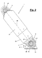
- Figure 2 shows the e.g. oblique or possibly also horizontal installation position of such a hydraulic shock absorber (1).
- the bearing (8) may possibly allow limited pivotal movements of the damper (1) about a transverse to its longitudinal axis (26) extending bearing axis (27) and consists for example according to Figure 2 of a bearing block (9) with one or two lateral bearing arms (28 ) for flying or bilateral recording of an inserted through the bearing eye (4) axis or sleeve.
- the bearing block (9) has a bottom plate (10) which is so far away from the axis (27) of the bearing eye (4), that for the operation and the occurring pivoting movements of the shock absorber sufficient clearance (11) or a clearance and a distance between the outside of the bearing eye (4) and the surrounding shell of the bottom piece (2) and the facing inner wall of the bottom plate (10).
- the hydraulic shock absorber (1) has a mechanical installation safety device (5) on at least one end piece (2, 3).
- the installation-mounting safety device (5) is located on the bottom-side end piece (2) or bottom piece of a pipe (21, 22, 23) and can cooperate with the bearing (8) to inhibit it.
- it can be arranged on the upper end piece or head piece (3) or on both end pieces (2,3) a mounting plate fuse (5).
- the installation safety device (5) can be created by a shaping of the end piece (2), e.g. with the storage (8) and in particular with the bearing block (9) cooperates and is tuned to it.
- the bearing (8) or the bearing block (9) can also have an adapted shape.
- the shape (s) can be asymmetric.
- the asymmetry can be e.g. refer to the longitudinal axis (26) of the shock absorber (1) or the piston rod (25) or the bearing axis (27).
- the installation safety device (5) can be designed and arranged differently.
- the installation-mounting safety device (5) has, for example, at least one securing element or molded part (6) deviating from the normal end-line contour on one side.
- the molded part (6) can cause an asymmetrical shaping of the end piece (2, 3) and, for example, as in the embodiment shown, can be formed as an outwardly directed projection (7), in particular as a nose or elongate rib on the casing of the end piece (2).
- the projection (7) can in this case have a height which is greater than the bearing clearance (11).
- the molded part (6) or the projection (7) is arranged asymmetrically to the longitudinal axis (26) and to the bearing eye (4) of the end piece (2,3).
- the molded part (6) is eg only on a shell side of the end piece (2,3). Due to the asymmetry, the correct mounting position or orientation of the shock absorber (1) immediately and in particular visually recognizable.
- the asymmetrical shape or the molded part (6) can serve as a pure indication of the correct mounting position or orientation. It can also be designed as a related to the correct mounting position and with a part of the bearing (8) cooperating mechanical stop and allow only for correct installation position or orientation of the shock absorber (1) assembly.
- the stop function can also serve to limit the movement of the damper (1) in the storage (8) and be adapted accordingly.
- the rib (7) is located on the outer wall and skirt of the end piece (2) or bottom piece and extends along the surface line and at the lower end in a limited arc around and e.g. concentric around the bearing eye (4).
- the rib (7) is arranged approximately in the mantle center of the bottom part (2) and extends from its upper end and the connection region to the tubes (22, 23) to approximately half the circumference of the bearing eye (4) or to the middle of the underside of the bottom piece (2).
- the fitting (6) or the projection (7) are in this case e.g. at the side of the bottom piece (2) pointing upwards in the oblique installation position.
- the shock absorber (1) can only be mounted in its oblique installation position by means of this installation safety device (5) if the molded part (6) and the projection (7) are located at the top and outside of the storage area.
- the shock absorber (1) are rotated by 180 °, the molding (6) or the projection (7) come to rest on the underside of the bottom part (2), an assembly would not possible.
- the projection (7) would strike the bottom plate (10) and because of the limited clearance (11) the bearing eye (4) raise so far that it is no longer aligned with the receiving openings in the bearing block (9) and thus prevents assembly ,
- the molding (6) may e.g. be designed as a groove-like or hole-like depression on the curved outer wall or the shell of an end piece, in particular of the bottom piece (2), and cooperate with a corresponding pin or cusp on the bearing (8).
- the recessed molded part (6) would have to be arranged on the underside of the bottom piece (2), wherein in the correct mounting position of the pin or bump positively engages the groove or hole-like depression and thus allows the assembly.
- At least one molding part (6) projecting or recessed in the direction of the bearing axis (27) can be arranged at another point of the end piece (2, 3), eg laterally next to the bearing eye (4)
- Storage (8) for example, with a bearing arm (28) or a cheek of the bearing block (9) abutment cooperates.
- a one-sided arrangement or an asymmetry on the tail (2,3) is present to mark the correct mounting position or to prevent false mounting positions by mechanical interaction.
- a shape adaptation of the bearing (8) is also possible here, for example by different shapes of the bearing arms (28).
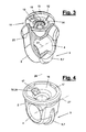
- FIGS 3 to 6 illustrate the design of the bottom valve (12) and the bottom piece (2).
- the bottom piece (2) is e.g. formed as a metallic molding or cast body and has the transverse bearing eye (4), which is designed as a cylindrical bore or through-channel. Above the bearing eye is a recessed valve seat (16).
- the bottom valve (12) has a substantially circular valve plate (13) which may be located at a suitable location, e.g. in the middle, a throttle valve (14).
- the throttle valve (14) allows the amount of oil required to compensate for the piston rod volume to flow out of the cylinder space located below the piston (24).
- the throttle valve (14) can be set harder for this than the throttle valve in the piston (24) to pass only this compensation amount. This compensating amount of oil is displaced when retracting the shock absorber (1) or the piston (24). When the shock absorber (1) or piston (24) is extended, the displaced oil quantity is returned, which occurs largely throttle-free via flow openings (15) in the valve plate (13) and a return plate which opens when it flows back.
- the flow openings (15) are arranged locally and in a limited angular range with respect to the cylinder and valve longitudinal axis. They extend, for example, in a semicircle around the throttle valve (14). In the other sector, the valve plate (13) is solid. In order to prevent a backflow of the obliquely mounted gas bubble located in the upper side in the working cylinder (22), the flow openings (15) are arranged on the underside. Even if the gas bubble should reach into the area of the bottom valve (12), can because of their buoyancy they do not migrate down so far that they pass through the flow openings (15).
- the installation safety device (5) is arranged and designed so that this desired bottom-side position of the flow openings (15) is ensured.
- a pivot bearing safety (18) is provided to ensure the correct assignment and installation position between the bottom piece (2) and the bottom valve (12). As a result, then the correct relationship to the mounting plate fuse (5) is guaranteed.
- the pivot lock (18) may e.g. also be designed as a positive mechanical security. For this purpose, e.g. on the underside of the valve plate (13) locally a projecting nose (19) and at the correct position associated with the valve seat (16) in the bottom piece (2) a corresponding recess (20).
- the bottom piece (2) has, on its end face facing the tubes (22, 23), the conically recessed valve seat (16) for receiving and centering the bottom valve (12).
- the valve seat (16) below the valve plate (13) has a trough for receiving and redirecting the compensating oil quantity.
- a centering (17) is arranged with recesses, which leads through the working cylinder (22) and an overflow of the compensating amount of oil in the circumferential gap to the also on the bottom piece (2) guided and supported Outer tube (23) allows.
- This relates to the design and arrangement of the mounting plate fuse (5) and the design and arrangement of the shock absorber (1).
- the shock absorber (1) can rotate around the lower bearing eye (4) in the oblique mounting position shown in FIG.
- the angle of rotation can be limited to one or both directions by the mounting plate fuse (5) or otherwise.
- Variable are the structural design and the kinematics of the bearing (8) and the end piece (2,3).
- the bearing (8) may be present instead of a pivot bearing a sliding bearing or a fixed bearing.
- the storage (8) must not be mobile.
Landscapes
- Engineering & Computer Science (AREA)
- General Engineering & Computer Science (AREA)
- Mechanical Engineering (AREA)
- Fluid-Damping Devices (AREA)
- Emergency Lowering Means (AREA)
Abstract
Description
Die Erfindung betrifft einen Stoßdämpfer mit den Merkmalen im Oberbegriff des Hauptanspruchs.The invention relates to a shock absorber having the features in the preamble of the main claim.
Hydraulische Stoßdämpfer mit ein oder mehreren Rohren, insbesondere Zweirohrstoßdämpfer, werden bisweilen in vorgeschriebenen Einbaulagen montiert. Bei einem symmetrischen Stoßdämpferaufbau lässt sich die Einbaulage nicht sicher erkennen, weshalb zur Kennzeichnung entsprechende Etiketten auf dem Stoßdämpfer aufgeklebt werden. Deren nachträgliche Anbringung ist allerdings fehlergefährdet.Hydraulic shock absorbers with one or more pipes, in particular two-pipe shock absorbers, are sometimes mounted in prescribed installation positions. In the case of a symmetrical shock absorber structure, the installation position can not be detected reliably, for which reason corresponding labels are glued to the shock absorber for identification. Their subsequent attachment, however, is at risk of error.
Es ist Aufgabe der vorliegenden Erfindung, einen verbesserten Stoßdämpfer aufzuzeigen.It is an object of the present invention to provide an improved shock absorber.
Die Erfindung löst diese Aufgabe mit den Merkmalen im Hauptanspruch.
Die mechanische Einbaulagensicherung an einem Endstück des Stoßdämpfers vereinfacht die Handhabung und lagerichtige Montage des Stoßdämpfers. Sie sichert die korrekte Einbaulage und Orientierung des Stoßdämpfers bei der Montage und verhindert Einbaufehler. Die Einbaulagensicherung wird herstellerseitig vorgesehen und kann durch eine geeignete Formgestaltung des Stoßdämpfers und ggf. der Lagerung geschaffen werden. Auf Etiketten und dergleichen andere Zusatzteile kann verzichtet werden. Die mechanische Einbaulagensicherung ist selbsterklärend und bedarf keiner schriftlichen Einweisung. Schriftliche Montagehinweise können entfallen. Die mechanische Einbaulagensicherung ist für Monteure international und ohne sprachenprobleme verständlich.The invention solves this problem with the features in the main claim.
The mechanical installation safety device on an end piece of the shock absorber simplifies the handling and correct installation of the shock absorber. It ensures the correct installation position and orientation of the shock absorber during assembly and prevents installation errors. The installation protection is provided by the manufacturer and can be created by a suitable design of the shock absorber and possibly the storage. On labels and the like other accessories can be omitted. The mechanical installation safety device is self-explanatory and requires no written instruction. Written installation instructions can be omitted. The mechanical installation protection is understandable for fitters internationally and without language problems.
Vorteilhafterweise wirkt die Einbaulagensicherung mit der Lagerung des Endstücks, vorzugsweise des bodenseitigen Endstücks bzw. Bodenstücks eines Dämpferrohrs, zusammen. Hierdurch kann sofort bei der Lagermontage die Einbaulage unmittelbar überprüft und ggf. korrigiert werden. Hierfür ist es günstig, dass die Einbaulagensicherung am Endstück angeordnet ist.Advantageously, the mounting-plate fuse with the storage of the tail, preferably the bottom-side end piece or bottom piece of a damper tube, together. As a result, the installation position can be checked immediately and corrected if necessary immediately during bearing mounting. For this it is favorable that the mounting rail safety is arranged on the tail.
Bei der mechanischen Einbaulagensicherung besteht außerdem eine feste und unveränderliche Zuordnung zwischen dem Sicherungselement und dem Stoßdämpfer, so dass Beschriftungsfehler oder andere Fehler wie beim Stand der Technik ausgeschlossen sind.In addition, the mechanical installation safety device is a fixed and unchangeable assignment between the fuse element and the shock absorber, so that inscription errors or other errors are excluded as in the prior art.
Die mechanische Einbaulagensicherung kann in unterschiedlicher weise ausgebildet sein. Ein von der normalen Endstückkontur abweichendes und z.B. asymmetrisches Formteil gibt einen sofort erkennbaren und leicht erfassbaren Einbaulagenhinweis. Es verhindert außerdem bei entsprechender Ausgestaltung in Verbindung mit der Lagerung, dass der Stoßdämpfer in der falschen Lage überhaupt montiert werden kann. Ein Sicherungselement oder Formteil in Gestalt einer vorstehenden Nase oder Rippe ist eine besonders einfache Ausgestaltung der Einbaulagensicherung, die wenig Aufwand erfordert und sich auch im Betrieb des Stoßdämpfers nicht nachteilig auswirkt. Eine solche Einbaulagensicherung kann außerdem eine Zusatzfunktion haben und z.B. den Schwenkwinkel des Stoßdämpfers begrenzen.The mechanical installation safety device can be designed in different ways. A deviating from the normal tail contour and e.g. asymmetric molded part gives an instantly recognizable and easily detectable installation orientation. It also prevents with appropriate design in connection with the storage that the shock absorber can be mounted in the wrong position at all. A securing element or molded part in the form of a protruding nose or rib is a particularly simple embodiment of the mounting device safety, which requires little effort and does not adversely affect the operation of the shock absorber. Such a mounting device fuse can also have an additional function and e.g. limit the swing angle of the shock absorber.
Bei einem Zweirohrstoßdämpfer empfiehlt sich eine Lagezuordnung der Einbaulagensicherung gegenüber den Durchflussöffnungen des Bodenventils. Diese Lagezuordnung kann über eine Drehlagensicherung zwischen Bodenventil und Ventilsitz am Endstück, insbesondere Bodenstück, zusätzlich abgesichert werden. Vorteilhafterweise sind beide Lagesicherungen am gleichen Bauteil, d.h. am Bodenstück, angeordnet und dort angeformt. Dies schließt verwechslungen, Fehler beim Zusammenbau des Stoßdämpfers sowie der Stoßdämpfermontage oder dergleichen aus.In the case of a twin-tube shock absorber, a positional assignment of the installation-mounting safety device with respect to the flow-through openings of the bottom valve is recommended. This position assignment can be additionally secured by means of a rotary ball valve between bottom valve and valve seat on the end piece, in particular bottom piece. Advantageously, both position fuses on the same component, ie on Bottom piece, arranged and molded there. This excludes confusion, failure in assembling the shock absorber as well as shock absorber mounting or the like.
In den unteransprüchen sind weitere vorteilhafte Ausgestaltungen der Erfindung angegeben.In the subclaims further advantageous embodiments of the invention are given.
Die Erfindung ist in den Zeichnungen beispielsweise und schematisch dargestellt. Im einzelnen zeigen:
- Figur 1:
- einen hydraulischen Stoßdämpfer mit einer Einbaulagensicherung in perspektivischer Explosionsdarstellung,
- Figur 2:
- eine Seitenansicht des Stoßdämpfers in schräger Einbaulage mit bodenseitiger Lagerung,
- Figur 3:
- eine teilweise aufgebrochene perspektivische Unteransicht eines Bodenstücks und eines Bodenventils des Stoßdämpfers,
- Figur 4:
- eine perspektivische Draufsicht auf das Bodenstück,
- Figur 5:
- eine teilweise geschnittene Seitenansicht des Bodenstücks und des abgehobenen Bodenventils und
- Figur 6:
- eine Draufsicht auf das Bodenstück.
- FIG. 1:
- a hydraulic shock absorber with an installation safety device in a perspective exploded view,
- FIG. 2:
- a side view of the shock absorber in an inclined mounting position with bottom-side storage,
- FIG. 3:
- a partially broken perspective bottom view of a bottom piece and a bottom valve of the shock absorber,
- FIG. 4:
- a perspective top view of the bottom piece,
- FIG. 5:
- a partially sectioned side view of the bottom piece and the raised bottom valve and
- FIG. 6:
- a plan view of the bottom piece.
Die Erfindung betrifft einen hydraulischen Dämpfer, insbesondere einen Stoßdämpfer (1) für Fahrzeuge oder dgl., der in unterschiedlicher Weise ausgebildet sein kann. Er kann insbesondere ein oder mehrere Rohre (21,22,23) aufweisen. Die Dämpferbauteile befinden sich im Inneren des hydraulischen Dämpfers (1). Der hydraulische Dämpfer (1) hat eine Außenrohrform, die keine Hinweise auf die Innenanordnung gibt. Er hat z.B. eine im wesentlichen zylindrische Außenrohrform, die über die Rohrlänge gleich bleibt und einen geschlossenen Mantel aufweist. Die Außenrohrform kann sich alternativ über die Länge ändern und dabei im wesentlichen symmetrisch zur Längsachse (26) des hydraulischen Dämpfers (1) sein. Die Querschnittsform kann beliebig, z.B. kreisrund, oval oder prismatisch sein und kann eine Symmetrie bezüglich der Längsachse (26) aufweisen.The invention relates to a hydraulic damper, in particular a shock absorber (1) for vehicles or the like., Which may be designed in different ways. In particular, it can have one or more tubes (21, 22, 23). The damper components are located inside the hydraulic damper (1). The hydraulic damper (1) has an outer tube shape, which gives no indication of the internal arrangement. He has, for example, a substantially cylindrical outer tube shape, which remains the same over the tube length and having a closed jacket. The Outer tube shape may alternatively change over the length and thereby be substantially symmetrical to the longitudinal axis (26) of the hydraulic damper (1). The cross-sectional shape may be arbitrary, for example circular, oval or prismatic and may have a symmetry with respect to the longitudinal axis (26).
In der gezeigten Ausführungsform handelt es sich um einen Zweirohrdämpfer mit einem Arbeitszylinder oder Innenrohr (22), welches von einem Außenrohr (23) mit radialem Abstand konzentrisch umgeben wird. Über das Außenrohr (23) kann ein Schutzrohr (21) gesteckt sein. Im Arbeitszylinder (22) befindet sich ein Kolben (24) mit einem Drosselventil und einem Überströmventil sowie einer Kolbenstange (25). Der Kolben (24) ist am einen Stangenende angeordnet. Am anderen Ende ist die Kolbenstange (25) durch ein mit dem Arbeitszylinder (22) und dem Außenrohr (23) verbundenes Endstück oder Kopfstück (3) verschieblich geführt und weist ein Lagerauge (4) auf.In the embodiment shown, it is a two-pipe damper with a working cylinder or inner tube (22) which is surrounded concentrically by an outer tube (23) with a radial distance. A protective tube (21) can be inserted over the outer tube (23). In the working cylinder (22) is a piston (24) with a throttle valve and an overflow valve and a piston rod (25). The piston (24) is arranged at one end of the rod. At the other end, the piston rod (25) by a with the working cylinder (22) and the outer tube (23) connected end piece or head piece (3) guided and has a bearing eye (4).
Bei hydraulischen Stoßdämpfern unterscheiden sich die beidseits des Kolbens (24) angeordneten Kammer- und Ölvolumina durch das Volumen der Kolbenstange (25), welches kompensiert werden soll. Zu diesem Zweck ist am bodenseitigen Ende des Arbeitszylinders (22) ein mit dem dortigen Endstück oder Bodenstück (2) zusammenwirkendes Bodenventil (12) angeordnet, welches ein Überströmen einer dem Kolbenstangenvolumen und der Eintauchtiefe entsprechenden Ölmenge aus dem Arbeitszylinder (22) in den zwischenraum zwischen dem Außenrohr (23) und dem Arbeitszylinder (22) ermöglicht. In diesem nach oben abgeschlossenen Zwischenraum befindet sich außerdem ein ggf. vorgespanntes Gaspolster, welches durch seine Kompressibilität eine Aufnahme der überströmenden ölmengen ermöglicht und andererseits eine Gegenkraft aufbaut. Durch diese Zweirohrtechnik ist der Arbeitszylinder (22) bei allen Kolbenstellungen stets vollkommen mit Hydrauliköl gefüllt.In the case of hydraulic shock absorbers, the chamber and oil volumes arranged on both sides of the piston (24) differ by the volume of the piston rod (25) which is to be compensated. For this purpose, at the bottom end of the working cylinder (22) with the local end piece or bottom piece (2) cooperating bottom valve (12) is arranged, which an overflow of the piston rod volume and the immersion depth corresponding amount of oil from the working cylinder (22) in the intermediate space between the outer tube (23) and the working cylinder (22) allows. In this upwardly closed space is also a possibly biased gas cushion, which allows its absorption by a recording of the overflowing amounts of oil and on the other hand builds up a counterforce. Due to this two-pipe technology, the working cylinder (22) is always completely filled with hydraulic oil in all piston positions filled.
Hydraulische Stoßdämpfer (1) und insbesondere der gezeigte Zweirohrstoßdämpfer werden bisweilen in einer vorgegebenen Einbaulage montiert, die z.B. einen störungsfreien Betrieb ermöglicht. Die Einhaltung einer bestimmten Einbaulage kann auch aus anderen Gründen vorgegeben oder vorteilhaft sein. Hierbei kann z.B. bei Zweirohrstoßdämpfern ein Rückströmen des Gaspolsters oder der Gasblase in den Arbeitszylinder (22) verhindert werden. Hierauf wird nachfolgend noch im einzelnen eingegangen. Figur 2 zeigt die z.B. schräge oder ggf. auch liegende Einbaulage eines solchen hydraulischen Stoßdämpfers (1).Hydraulic shock absorbers (1) and in particular the twin-tube shock absorbers shown are sometimes mounted in a predetermined mounting position, e.g. allows trouble-free operation. Compliance with a particular installation position may also be predetermined or advantageous for other reasons. Here, e.g. In two-pipe shock absorbers, a backflow of the gas cushion or the gas bubble into the working cylinder (22) can be prevented. This will be discussed in detail below. Figure 2 shows the e.g. oblique or possibly also horizontal installation position of such a hydraulic shock absorber (1).
Aus der über die Längsachse (26) im wesentlichen gleich bleibenden oder achssymmetrischen Außenrohrform ist die korrekte Einbaulage nicht ohne weiteres ersichtlich.From the over the longitudinal axis (26) substantially constant or axisymmetric outer tube shape, the correct mounting position is not readily apparent.
Am Bodenteil (2) ist ebenfalls ein Lagerauge (4) für die drehbare Aufnahme an einer bodenseitigen Lagerung (8) vorgesehen. Die Lagerung (8) kann ggf. begrenzte Schwenkbewegungen des Dämpfers (1) um eine quer zu seiner Längsachse (26) verlaufende Lagerachse (27) ermöglichen und besteht z.B. gemäß Figur 2 aus einem Lagerbock (9) mit ein oder zwei seitlichen Lagerarmen (28) zur fliegenden oder beidseitigen Aufnahme einer durch das Lagerauge (4) gesteckten Achse oder Hülse. Der Lagerbock (9) weist eine Bodenplatte (10) auf, die so weit von der Achse (27) des Lagerauges (4) distanziert ist, dass sich für den Betrieb und die dabei auftretenden Schwenkbewegungen des Stoßdämpfers eine ausreichende Lagerluft (11) bzw. ein Lagerspiel und ein Abstand zwischen der Außenseite des Lagerauges (4) bzw. dem umgebenden Mantel des Bodenstücks (2) und der zugekehrten Innenwand der Bodenplatte (10) ergibt.At the bottom part (2) is also a bearing eye (4) for the rotatable mounting on a bottom-side mounting (8) is provided. The bearing (8) may possibly allow limited pivotal movements of the damper (1) about a transverse to its longitudinal axis (26) extending bearing axis (27) and consists for example according to Figure 2 of a bearing block (9) with one or two lateral bearing arms (28 ) for flying or bilateral recording of an inserted through the bearing eye (4) axis or sleeve. The bearing block (9) has a bottom plate (10) which is so far away from the axis (27) of the bearing eye (4), that for the operation and the occurring pivoting movements of the shock absorber sufficient clearance (11) or a clearance and a distance between the outside of the bearing eye (4) and the surrounding shell of the bottom piece (2) and the facing inner wall of the bottom plate (10).
Um die korrekte Einbaulage und Orientierung des Stoßdämpfers (1) anzuzeigen und darüber hinaus sicherzustellen, weist der hydraulische Stoßdämpfer (1) an mindestens einem Endstück (2,3) eine mechanische Einbaulagensicherung (5) auf. In der gezeigten und bevorzugten Ausführungsform befindet sich die Einbaulagensicherung (5) am bodenseitigen Endstück (2) oder Bodenstück eines Rohrs (21,22,23) und kann mit der Lagerung (8) hemmfähig zusammenwirken. Alternativ kann eine Einbaulagensicherung (5) auch am oberen Endstück oder Kopfstück (3) oder an beiden Endstücken (2,3) angeordnet sein.In order to indicate and moreover to ensure the correct installation position and orientation of the shock absorber (1), the hydraulic shock absorber (1) has a mechanical installation safety device (5) on at least one end piece (2, 3). In the shown and preferred embodiment, the installation-mounting safety device (5) is located on the bottom-side end piece (2) or bottom piece of a pipe (21, 22, 23) and can cooperate with the bearing (8) to inhibit it. Alternatively it can be arranged on the upper end piece or head piece (3) or on both end pieces (2,3) a mounting plate fuse (5).
Die Einbaulagensicherung (5) kann durch eine Formgebung des Endstücks (2) geschaffen werden, die z.B. mit der Lagerung (8) und insbesondere mit dem Lagerbock (9) zusammenwirkt und darauf abgestimmt ist. Die Lagerung (8) oder der Lagerbock (9) können dabei ebenfalls eine angepasste Formgebung aufweisen. Die Formgebung(en) kann/können asymmetrisch sein. Die Asymmetrie kann sich z.B. auf die Längsachse (26) des Stoßdämpfers (1) oder der Kolbenstange (25) oder die Lagerachse (27) beziehen. Die Einbaulagensicherung (5) kann unterschiedlich ausgebildet und angeordnet sein.The installation safety device (5) can be created by a shaping of the end piece (2), e.g. with the storage (8) and in particular with the bearing block (9) cooperates and is tuned to it. The bearing (8) or the bearing block (9) can also have an adapted shape. The shape (s) can be asymmetric. The asymmetry can be e.g. refer to the longitudinal axis (26) of the shock absorber (1) or the piston rod (25) or the bearing axis (27). The installation safety device (5) can be designed and arranged differently.
Die Einbaulagensicherung (5) weist z.B. mindestens ein von der normalen Endstückkontur einseitig abweichendes Sicherungselement oder Formteil (6) auf. Das Formteil (6) kann eine asymmetrische Formgebung des Endstücks (2,3) bewirken und z.B. wie in der gezeigten Ausführungsform als nach außen gerichteter Vorsprung (7), insbesondere als Nase oder längliche Rippe am Mantel des Endstücks (2) ausgebildet sein. Der Vorsprung (7) kann hierbei eine Höhe haben, die größer ist als die Lagerluft (11). Das Formteil (6) bzw. der Vorsprung (7) ist dabei asymmetrisch zur Längsachse (26) und zum Lagerauge (4) des Endstücks (2,3) angeordnet. Das Formteil (6) befindet sich z.B. nur an einer Mantelseite des Endstücks (2,3). Durch die Asymmetrie ist die korrekte Einbaulage oder Orientierung des Stoßdämpfers (1) sofort und insbesondere optisch erkennbar.The installation-mounting safety device (5) has, for example, at least one securing element or molded part (6) deviating from the normal end-line contour on one side. The molded part (6) can cause an asymmetrical shaping of the end piece (2, 3) and, for example, as in the embodiment shown, can be formed as an outwardly directed projection (7), in particular as a nose or elongate rib on the casing of the end piece (2). The projection (7) can in this case have a height which is greater than the bearing clearance (11). The molded part (6) or the projection (7) is arranged asymmetrically to the longitudinal axis (26) and to the bearing eye (4) of the end piece (2,3). The molded part (6) is eg only on a shell side of the end piece (2,3). Due to the asymmetry, the correct mounting position or orientation of the shock absorber (1) immediately and in particular visually recognizable.
Die asymmetrische Formgebung bzw. das Formteil (6) kann als reine Anzeige für die korrekte Einbaulage oder Orientierung dienen. Sie kann ferner als ein auf die korrekte Einbaulage bezogener und mit einem Teil der Lagerung (8) zusammenwirkender mechanischer Anschlag ausgebildet sein und nur bei korrekter Einbaulage oder Orientierung des Stoßdämpfers (1) eine Montage ermöglichen. Die Anschlagfunktion kann außerdem zur Begrenzung der Bewegung des Dämpfers (1) in der Lagerung (8) dienen und entsprechend angepasst sein.The asymmetrical shape or the molded part (6) can serve as a pure indication of the correct mounting position or orientation. It can also be designed as a related to the correct mounting position and with a part of the bearing (8) cooperating mechanical stop and allow only for correct installation position or orientation of the shock absorber (1) assembly. The stop function can also serve to limit the movement of the damper (1) in the storage (8) and be adapted accordingly.
Wie Figur 3 bis 6 verdeutlichen, befindet sich die Rippe (7) an der Außenwandung und dem Mantel des Endstücks (2) oder Bodenstücks und erstreckt sich längs der Mantellinie und am unteren Ende in einem begrenzten Bogen rund und z.B. konzentrisch um das Lagerauge (4). Die Rippe (7) ist etwa in der Mantelmitte des Bodenteils (2) angeordnet und reicht von dessen oberem Ende und dem Anschlussbereich an die Rohre (22,23) bis etwa zum halben Umfang des Lagerauges (4) bzw. bis zur Mitte der Unterseite des Bodenstücks (2). Das Formstück (6) bzw. der Vorsprung (7) befinden sich dabei z.B. an der in der schrägen Einbaulage nach oben weisenden Mantelseite des Bodenstücks (2).As shown in Figures 3 to 6, the rib (7) is located on the outer wall and skirt of the end piece (2) or bottom piece and extends along the surface line and at the lower end in a limited arc around and e.g. concentric around the bearing eye (4). The rib (7) is arranged approximately in the mantle center of the bottom part (2) and extends from its upper end and the connection region to the tubes (22, 23) to approximately half the circumference of the bearing eye (4) or to the middle of the underside of the bottom piece (2). The fitting (6) or the projection (7) are in this case e.g. at the side of the bottom piece (2) pointing upwards in the oblique installation position.
Wie Figur 2 verdeutlicht, kann durch diese Einbaulagensicherung (5) der Stoßdämpfer (1) in seiner schrägen Einbaulage nur dann montiert werden, wenn das Formteil (6) und der Vorsprung (7) sich an der Oberseite und außerhalb des Lagerbereichs befinden. Würde der Stoßdämpfer (1) um 180° verdreht werden, wobei das Formteil (6) bzw. der Vorsprung (7) an der Unterseite des Bodenteils (2) zu liegen kommen, wäre eine Montage nicht möglich. Der Vorsprung (7) würde an der Bodenplatte (10) anschlagen und wegen der begrenzten Lagerluft (11) das Lagerauge (4) so weit nach oben anheben, dass es nicht mehr mit den Aufnahmeöffnungen im Lagerbock (9) fluchtet und somit eine Montage verhindert.As illustrated in FIG. 2, the shock absorber (1) can only be mounted in its oblique installation position by means of this installation safety device (5) if the molded part (6) and the projection (7) are located at the top and outside of the storage area. Would the shock absorber (1) are rotated by 180 °, the molding (6) or the projection (7) come to rest on the underside of the bottom part (2), an assembly would not possible. The projection (7) would strike the bottom plate (10) and because of the limited clearance (11) the bearing eye (4) raise so far that it is no longer aligned with the receiving openings in the bearing block (9) and thus prevents assembly ,
Abwandlungen der gezeigten Ausführungsform der mechanischen Einbaulagensicherung (5) sind in verschiedener Weise möglich. Das Formteil (6) kann z.B. als rinnenartige oder lochartige Vertiefung an der gebogenen Außenwandung bzw. dem Mantel eines Endstücks, insbesondere des Bodenstücks (2), ausgebildet sein und mit einem entsprechenden zapfen oder Höcker an der Lagerung (8) zusammenwirken. In diesem Fall müsste das vertiefte Formteil (6) an der Unterseite des Bodenstücks (2) angeordnet sein, wobei in korrekter Einbaulage der Zapfen oder Höcker formschlüssig in die Rinne oder bohrungsartige Vertiefung eingreift und damit die Montage ermöglicht. Wenn versucht wird, den Stoßdämpfer (1) verdreht in Falschlage einzubauen, drücken der Höcker oder Zapfen gegen die unvertiefte Wandung des Bodenstücks (2), so dass auch in diesem Fall das Lagerauge (4) und der Lagerbock (9) nicht zur Deckung gebracht werden können.Modifications of the illustrated embodiment of the mechanical installation safety device (5) are possible in various ways. The molding (6) may e.g. be designed as a groove-like or hole-like depression on the curved outer wall or the shell of an end piece, in particular of the bottom piece (2), and cooperate with a corresponding pin or cusp on the bearing (8). In this case, the recessed molded part (6) would have to be arranged on the underside of the bottom piece (2), wherein in the correct mounting position of the pin or bump positively engages the groove or hole-like depression and thus allows the assembly. When attempting to install the shock absorber (1) twisted in wrong position, press the hump or pin against the unfetched wall of the bottom piece (2), so that in this case the bearing eye (4) and the bearing block (9) not coincided can be.
In einer weiteren Abwandlung kann an anderer Stelle des Endstücks (2,3), z.B. seitlich neben dem Lagerauge (4), mindestens ein in Richtung der Lagerachse (27) vorspringendes oder vertieftes Formteil (6) angeordnet sein, welches mit einem anderen Teil der Lagerung (8), z.B. mit einem Lagerarm (28) oder einer Wange des Lagerbocks (9) anschlagmäßig zusammenwirkt. In diesem Fall ist wiederum eine einseitige Anordnung bzw. eine Asymmetrie am Endstück (2,3) vorhanden, um die korrekte Einbaulage zu kennzeichnen bzw. falsche Montagelagen durch mechanisches zusammenwirken zu verhindern. Eine Formanpassung der Lagerung (8) ist hier ebenfalls möglich, z.B. durch unterschiedliche Formgebungen der Lagerarme (28).In a further modification, at least one molding part (6) projecting or recessed in the direction of the bearing axis (27) can be arranged at another point of the end piece (2, 3), eg laterally next to the bearing eye (4) Storage (8), for example, with a bearing arm (28) or a cheek of the bearing block (9) abutment cooperates. In this case, in turn, a one-sided arrangement or an asymmetry on the tail (2,3) is present to mark the correct mounting position or to prevent false mounting positions by mechanical interaction. A shape adaptation of the bearing (8) is also possible here, for example by different shapes of the bearing arms (28).
Figur 3 bis 6 verdeutlichen die Gestaltung des Bodenventils (12) und des Bodenstücks (2). Das Bodenstück (2) ist z.B. als metallischer Formkörper oder Gusskörper ausgebildet und weist das quer liegende Lagerauge (4) auf, welches als zylindrische Bohrung oder Durchgangskanal ausgebildet ist. Oberhalb des Lagerauges befindet sich ein vertiefter Ventilsitz (16).Figures 3 to 6 illustrate the design of the bottom valve (12) and the bottom piece (2). The bottom piece (2) is e.g. formed as a metallic molding or cast body and has the transverse bearing eye (4), which is designed as a cylindrical bore or through-channel. Above the bearing eye is a recessed valve seat (16).
Das Bodenventil (12) besitzt eine im wesentlichen kreisrunde Ventilplatte (13), die an geeigneter Stelle, z.B. in der Mitte, ein Drosselventil (14) aufweist. Das Drosselventil (14) lässt die zur Kompensation des Kolbenstangenvolumens erforderliche Ölmenge aus dem unterhalb des Kolbens (24) befindlichen Zylinderraum durchströmen. Das Drosselventil (14) kann hierfür härter eingestellt werden, als das Drosselventil im Kolben (24), um nur diese Kompensationsmenge durchzulassen. Diese kompensierende Ölmenge wird beim Einfahren des Stoßdämpfers (1) bzw. des Kolbens (24) verdrängt. Beim Ausfahren des Stoßdämpfers (1) bzw. Kolbens (24) wird die verdrängte Ölmenge wieder zurück geführt, was weitgehend drosselfrei über Durchflussöffnungen (15) in der ventilplatte (13) und eine beim Rückströmen sich öffnende Rückschlagplatte geschieht.The bottom valve (12) has a substantially circular valve plate (13) which may be located at a suitable location, e.g. in the middle, a throttle valve (14). The throttle valve (14) allows the amount of oil required to compensate for the piston rod volume to flow out of the cylinder space located below the piston (24). The throttle valve (14) can be set harder for this than the throttle valve in the piston (24) to pass only this compensation amount. This compensating amount of oil is displaced when retracting the shock absorber (1) or the piston (24). When the shock absorber (1) or piston (24) is extended, the displaced oil quantity is returned, which occurs largely throttle-free via flow openings (15) in the valve plate (13) and a return plate which opens when it flows back.
Die Durchflussöffnungen (15) sind lokal und in einem begrenzten Winkelbereich gegenüber der Zylinder- und Ventillängsachse angeordnet. Sie erstrecken sich z.B. in einem Halbkreis rund um das Drosselventil (14). Im anderen Sektor ist die Ventilplatte (13) massiv ausgebildet. Um ein Rückströmen der in schräger Einbaulage sich an der Oberseite befindlichen Gasblase in den Arbeitszylinder (22) zu verhindern, sind die Durchflussöffnungen (15) an der Unterseite angeordnet. Selbst wenn die Gasblase bis in den Bereich des Bodenventils (12) gelangen sollte, kann sie wegen ihres Auftriebs nicht so weit nach unten wandern, dass sie durch die Durchflussöffnungen (15) gelangt.The flow openings (15) are arranged locally and in a limited angular range with respect to the cylinder and valve longitudinal axis. They extend, for example, in a semicircle around the throttle valve (14). In the other sector, the valve plate (13) is solid. In order to prevent a backflow of the obliquely mounted gas bubble located in the upper side in the working cylinder (22), the flow openings (15) are arranged on the underside. Even if the gas bubble should reach into the area of the bottom valve (12), can because of their buoyancy they do not migrate down so far that they pass through the flow openings (15).
Zwischen der Anordnung der Durchflussöffnungen (15) in der vorgesehenen schrägen Einbaulage und der mechanischen Einbaulagensicherung (5) gibt es eine Beziehung. Die Einbaulagensicherung (5) ist so angeordnet und ausgebildet, dass diese gewünschte bodenseitige Lage der Durchflussöffnungen (15) gewährleistet ist.There is a relationship between the arrangement of the flow openings (15) in the intended oblique installation position and the mechanical installation safety device (5). The installation safety device (5) is arranged and designed so that this desired bottom-side position of the flow openings (15) is ensured.
Andererseits ist eine Drehlagensicherung (18) vorgesehen, um zwischen dem Bodenstück (2) und dem Bodenventil (12) die korrekte Zuordnung und Einbaulage sicherzustellen. Hierdurch ist dann auch die richtige Beziehung zur Einbaulagensicherung (5) gewährleistet. Die Drehlagensicherung (18) kann z.B. ebenfalls als formschlüssige mechanische Sicherung ausgebildet sein. Hierfür ist z.B. an der Unterseite der Ventilplatte (13) lokal eine vorspringende Nase (19) und an der lagerichtig zugehörigen Stelle am Ventilsitz (16) im Bodenstück (2) eine entsprechende Vertiefung (20) angeordnet.On the other hand, a pivot bearing safety (18) is provided to ensure the correct assignment and installation position between the bottom piece (2) and the bottom valve (12). As a result, then the correct relationship to the mounting plate fuse (5) is guaranteed. The pivot lock (18) may e.g. also be designed as a positive mechanical security. For this purpose, e.g. on the underside of the valve plate (13) locally a projecting nose (19) and at the correct position associated with the valve seat (16) in the bottom piece (2) a corresponding recess (20).
Das Bodenstück (2) weist an seiner zu den Rohren (22,23) gewandten Stirnseite den kegelförmig vertieften Ventilsitz (16) zur Aufnahme und zentrierenden Führung des Bodenventils (12) auf. Der Ventilsitz (16) bietet unterhalb der Ventilplatte (13) eine Wanne zur Aufnahme und Umleitung der Kompensations-Ölmenge. An der den Ventilsitz (16) umgebenden ringförmigen Wandung ist eine Zentrierung (17) mit Ausnehmungen angeordnet, welche durch den Arbeitszylinder (22) führt und ein Überströmen der kompensierenden Ölmenge in den umfangsseitigen Zwischenraum zu dem ebenfalls an dem Bodenstück (2) geführten und abgestützten Außenrohr (23) ermöglicht.The bottom piece (2) has, on its end face facing the tubes (22, 23), the conically recessed valve seat (16) for receiving and centering the bottom valve (12). The valve seat (16) below the valve plate (13) has a trough for receiving and redirecting the compensating oil quantity. At the valve seat (16) surrounding the annular wall a centering (17) is arranged with recesses, which leads through the working cylinder (22) and an overflow of the compensating amount of oil in the circumferential gap to the also on the bottom piece (2) guided and supported Outer tube (23) allows.
Abwandlungen der beschriebenen Ausführungsformen sind in verschiedener Weise möglich. Dies betrifft die Ausbildung und Anordnung der Einbaulagensicherung (5) sowie die Ausgestaltung und Anordnung des Stoßdämpfers (1). Der Stoßdämpfer (1) kann in der in Figur 2 gezeigten schrägen Einbaulage um das untere Lagerauge (4) drehen. Der Drehwinkel kann nach ein oder beiden Richtungen durch die Einbaulagensicherung (5) oder auf andere Weise begrenzt werden.Modifications of the described embodiments are possible in various ways. This relates to the design and arrangement of the mounting plate fuse (5) and the design and arrangement of the shock absorber (1). The shock absorber (1) can rotate around the lower bearing eye (4) in the oblique mounting position shown in FIG. The angle of rotation can be limited to one or both directions by the mounting plate fuse (5) or otherwise.
Variabel sind die konstruktive Gestaltung und die Kinematik der Lagerung (8) und des Endstücks (2,3). Z.B. kann statt einer Schwenklagerung eine Schiebelagerung oder eine Festlagerung vorhanden sein. Die Lagerung (8) muss auch nicht beweglich sein. Abwandelbar sind ferner die sonstige konstruktive Gestaltung und der Einsatzbereich des Dämpfers (1).Variable are the structural design and the kinematics of the bearing (8) and the end piece (2,3). For example, may be present instead of a pivot bearing a sliding bearing or a fixed bearing. The storage (8) must not be mobile. Can also be modified, the other structural design and the application of the damper (1).
Die Merkmale der gezeigten und beschriebenen Ausführungsbeispiele können auch beliebig untereinander vertauscht und kombiniert werden.The features of the embodiments shown and described can also be interchanged and combined with each other.
- 11
- Stossdämpfershock absorber
- 22
- Endstück, BodenstückTail, bottom piece
- 33
- Endstück, KopfstückTail, head piece
- 44
- Lageraugebearing eye
- 55
- Lagensicherung, EinbaulagensicherungLocation protection, installation protection
- 66
- Formteilmolding
- 77
- Vorsprung, Nase, RippeProjection, nose, rib
- 88th
- Lagerungstorage
- 99
- Lagerbockbearing block
- 1010
- Bodenplattebaseplate
- 1111
- Lagerluftclearance
- 1212
- Bodenventilbottom valve
- 1313
- Ventilplattevalve plate
- 1414
- Drosselventilthrottle valve
- 1515
- DurchflussöffnungFlow opening
- 1616
- Ventilsitzvalve seat
- 1717
- Zentrierungcentering
- 1818
- Lagensicherung, DrehlagensicherungLayer protection, rotary latches
- 1919
- Nasenose
- 2020
- Vertiefungdeepening
- 2121
- Schutzrohrthermowell
- 2222
- Arbeitszylinder, InnenrohrWorking cylinder, inner tube
- 2323
- Außenrohrouter tube
- 2424
- Kolbenpiston
- 2525
- Kolbenstangepiston rod
- 2626
- Längsachselongitudinal axis
- 2727
- Lagerachsebearing axle
- 2828
- Lagerarmbearing arm
Claims (17)
Applications Claiming Priority (1)
| Application Number | Priority Date | Filing Date | Title |
|---|---|---|---|
| DE202006004598U DE202006004598U1 (en) | 2006-03-21 | 2006-03-21 | Shock absorber with mounting rail safety device |
Publications (2)
| Publication Number | Publication Date |
|---|---|
| EP1840407A1 true EP1840407A1 (en) | 2007-10-03 |
| EP1840407B1 EP1840407B1 (en) | 2010-04-28 |
Family
ID=38283036
Family Applications (1)
| Application Number | Title | Priority Date | Filing Date |
|---|---|---|---|
| EP07005656A Not-in-force EP1840407B1 (en) | 2006-03-21 | 2007-03-20 | Shock absorbers with mounting position protection |
Country Status (3)
| Country | Link |
|---|---|
| EP (1) | EP1840407B1 (en) |
| AT (1) | ATE466212T1 (en) |
| DE (2) | DE202006004598U1 (en) |
Cited By (1)
| Publication number | Priority date | Publication date | Assignee | Title |
|---|---|---|---|---|
| WO2008116536A1 (en) * | 2007-03-23 | 2008-10-02 | Saf-Holland Gmbh | Shock absorbers |
Families Citing this family (3)
| Publication number | Priority date | Publication date | Assignee | Title |
|---|---|---|---|---|
| DE202009001400U1 (en) * | 2009-02-05 | 2010-06-24 | Al-Ko Kober Ag | shock absorber |
| DE102016225341B4 (en) * | 2016-12-16 | 2020-03-26 | Zf Friedrichshafen Ag | Hydraulic double tube shock absorber |
| DE102018117775A1 (en) * | 2018-07-23 | 2020-01-23 | Stabilus Gmbh | Length measurement on piston-cylinder arrangements |
Citations (4)
| Publication number | Priority date | Publication date | Assignee | Title |
|---|---|---|---|---|
| WO1993017255A1 (en) | 1992-02-24 | 1993-09-02 | Monroe Auto Equipment Company | Base valve for a shock absorber |
| FR2779196A1 (en) | 1998-05-28 | 1999-12-03 | Mannesmann Sachs Ag | Telescopic suspension damper for motor vehicle |
| DE10108686A1 (en) | 2001-02-23 | 2002-09-05 | Audi Ag | Fastener arrangement esp. for telescopic shock absorber for motor vehicles has rubber-metal sleeve bearing with fastening brackets aligned asymmetrically to bearing stud |
| DE10359638B3 (en) | 2003-09-04 | 2005-04-21 | Zf Friedrichshafen Ag | Bearing for a vibration damper |
Family Cites Families (8)
| Publication number | Priority date | Publication date | Assignee | Title |
|---|---|---|---|---|
| US2357920A (en) * | 1943-10-11 | 1944-09-12 | Monroe Auto Equipment Co | Shock absorber |
| FR2437310A1 (en) * | 1978-09-28 | 1980-04-25 | Allinquant J G | FIXING DEVICE FOR TELESCOPIC SUSPENSION SHOCK ABSORBERS |
| DE8436001U1 (en) * | 1984-12-08 | 1985-03-14 | Fritz Bauer + Söhne oHG, 8503 Altdorf | HYDRAULIC DOUBLE TUBE SHOCK ABSORBER |
| DE3905710C2 (en) * | 1989-02-24 | 1996-04-18 | Man Nutzfahrzeuge Ag | Level adjustment of the axle springs in commercial vehicles |
| DE4105763A1 (en) * | 1991-02-23 | 1992-08-27 | Suspa Compart Ag | LINKING A VIBRATION DAMPER FOR A WASHING MACHINE |
| DE4327915C2 (en) * | 1993-08-20 | 2000-12-07 | Mannesmann Sachs Ag | Hydraulic telescopic vibration damper |
| US6843472B2 (en) * | 2003-01-21 | 2005-01-18 | The Pullman Company | Upper shock mount isolator with integral air spring housing pivot bearing |
| DE10348526B4 (en) * | 2003-10-18 | 2008-02-07 | Zf Friedrichshafen Ag | Piston-cylinder unit with prepared draining point |
-
2006
- 2006-03-21 DE DE202006004598U patent/DE202006004598U1/en not_active Expired - Lifetime
-
2007
- 2007-03-20 AT AT07005656T patent/ATE466212T1/en active
- 2007-03-20 DE DE502007003559T patent/DE502007003559D1/en active Active
- 2007-03-20 EP EP07005656A patent/EP1840407B1/en not_active Not-in-force
Patent Citations (5)
| Publication number | Priority date | Publication date | Assignee | Title |
|---|---|---|---|---|
| WO1993017255A1 (en) | 1992-02-24 | 1993-09-02 | Monroe Auto Equipment Company | Base valve for a shock absorber |
| FR2779196A1 (en) | 1998-05-28 | 1999-12-03 | Mannesmann Sachs Ag | Telescopic suspension damper for motor vehicle |
| DE19823878C1 (en) | 1998-05-28 | 1999-12-23 | Mannesmann Sachs Ag | Two-tube vibration damper with a compensating element |
| DE10108686A1 (en) | 2001-02-23 | 2002-09-05 | Audi Ag | Fastener arrangement esp. for telescopic shock absorber for motor vehicles has rubber-metal sleeve bearing with fastening brackets aligned asymmetrically to bearing stud |
| DE10359638B3 (en) | 2003-09-04 | 2005-04-21 | Zf Friedrichshafen Ag | Bearing for a vibration damper |
Cited By (1)
| Publication number | Priority date | Publication date | Assignee | Title |
|---|---|---|---|---|
| WO2008116536A1 (en) * | 2007-03-23 | 2008-10-02 | Saf-Holland Gmbh | Shock absorbers |
Also Published As
| Publication number | Publication date |
|---|---|
| ATE466212T1 (en) | 2010-05-15 |
| DE502007003559D1 (en) | 2010-06-10 |
| EP1840407B1 (en) | 2010-04-28 |
| DE202006004598U1 (en) | 2007-08-02 |
Similar Documents
| Publication | Publication Date | Title |
|---|---|---|
| DE2903863C2 (en) | Hydraulic shock absorber | |
| EP4323688B1 (en) | Fastening system for pressure vessels | |
| DE3313613C2 (en) | ||
| EP0135807B1 (en) | Arrangement for connecting a helical spring to a motor vehicle wheel suspension arm | |
| EP1840407B1 (en) | Shock absorbers with mounting position protection | |
| DE10315645A1 (en) | Hydraulically damping rubber bush bearing has radially inner lying wall of each fluid filled chamber changing from section parallel to bearing axis into section at angle to it, forming undercut in direction of bearing axis | |
| EP4386254A2 (en) | Pressure vessel having multiple lateral outflow apertures | |
| DE2065602A1 (en) | DEVICE FOR VIBRATION ATTENUATION OF FREE-HANGING CABLES | |
| DE202009007569U1 (en) | cylinder arrangement | |
| DE19923456C5 (en) | Level control valve for the air suspension of vehicles, especially commercial vehicles | |
| DE2747860A1 (en) | SLIDE VALVE | |
| DE102011084475B4 (en) | Steering knuckle or a pivot bearing of a vehicle axle | |
| DE8705346U1 (en) | Limitation for traffic areas | |
| DE2743271B2 (en) | Lockable fuel tank cap, in particular for motor vehicles | |
| AT406882B (en) | SECURITY FITTING | |
| EP1878939A2 (en) | Lightweight plunger | |
| DE8717760U1 (en) | Ball joint with torsion angle measuring device | |
| DE8511789U1 (en) | Shock absorbers, in particular for industrial purposes | |
| DE10108537C2 (en) | Heat controlled fire protection valve | |
| DE202018102956U1 (en) | Hinge for a toilet seat set | |
| DE8311750U1 (en) | Vibration damper, strut or strut insert for vehicles | |
| DE102004038529B4 (en) | Motorcycle with adjustable strut | |
| DE102005008788B4 (en) | Swing block lock for a self loading rifle | |
| DE10014796B4 (en) | Topless high pressure valve | |
| DE1901783C (en) | Container for heavy water for cooling tubular fuel elements of an atomic nuclear reactor |
Legal Events
| Date | Code | Title | Description |
|---|---|---|---|
| PUAI | Public reference made under article 153(3) epc to a published international application that has entered the european phase |
Free format text: ORIGINAL CODE: 0009012 |
|
| AK | Designated contracting states |
Kind code of ref document: A1 Designated state(s): AT BE BG CH CY CZ DE DK EE ES FI FR GB GR HU IE IS IT LI LT LU LV MC MT NL PL PT RO SE SI SK TR |
|
| AX | Request for extension of the european patent |
Extension state: AL BA HR MK YU |
|
| 17P | Request for examination filed |
Effective date: 20080317 |
|
| 17Q | First examination report despatched |
Effective date: 20080422 |
|
| AKX | Designation fees paid |
Designated state(s): AT BE BG CH CY CZ DE DK EE ES FI FR GB GR HU IE IS IT LI LT LU LV MC MT NL PL PT RO SE SI SK TR |
|
| GRAJ | Information related to disapproval of communication of intention to grant by the applicant or resumption of examination proceedings by the epo deleted |
Free format text: ORIGINAL CODE: EPIDOSDIGR1 |
|
| GRAP | Despatch of communication of intention to grant a patent |
Free format text: ORIGINAL CODE: EPIDOSNIGR1 |
|
| GRAP | Despatch of communication of intention to grant a patent |
Free format text: ORIGINAL CODE: EPIDOSNIGR1 |
|
| GRAS | Grant fee paid |
Free format text: ORIGINAL CODE: EPIDOSNIGR3 |
|
| GRAA | (expected) grant |
Free format text: ORIGINAL CODE: 0009210 |
|
| AK | Designated contracting states |
Kind code of ref document: B1 Designated state(s): AT BE BG CH CY CZ DE DK EE ES FI FR GB GR HU IE IS IT LI LT LU LV MC MT NL PL PT RO SE SI SK TR |
|
| REG | Reference to a national code |
Ref country code: GB Ref legal event code: FG4D Free format text: NOT ENGLISH |
|
| REG | Reference to a national code |
Ref country code: CH Ref legal event code: EP |
|
| REG | Reference to a national code |
Ref country code: IE Ref legal event code: FG4D Free format text: LANGUAGE OF EP DOCUMENT: GERMAN |
|
| REF | Corresponds to: |
Ref document number: 502007003559 Country of ref document: DE Date of ref document: 20100610 Kind code of ref document: P |
|
| REG | Reference to a national code |
Ref country code: NL Ref legal event code: VDEP Effective date: 20100428 |
|
| LTIE | Lt: invalidation of european patent or patent extension |
Effective date: 20100428 |
|
| PG25 | Lapsed in a contracting state [announced via postgrant information from national office to epo] |
Ref country code: ES Free format text: LAPSE BECAUSE OF FAILURE TO SUBMIT A TRANSLATION OF THE DESCRIPTION OR TO PAY THE FEE WITHIN THE PRESCRIBED TIME-LIMIT Effective date: 20100808 Ref country code: SE Free format text: LAPSE BECAUSE OF FAILURE TO SUBMIT A TRANSLATION OF THE DESCRIPTION OR TO PAY THE FEE WITHIN THE PRESCRIBED TIME-LIMIT Effective date: 20100428 Ref country code: NL Free format text: LAPSE BECAUSE OF FAILURE TO SUBMIT A TRANSLATION OF THE DESCRIPTION OR TO PAY THE FEE WITHIN THE PRESCRIBED TIME-LIMIT Effective date: 20100428 Ref country code: LT Free format text: LAPSE BECAUSE OF FAILURE TO SUBMIT A TRANSLATION OF THE DESCRIPTION OR TO PAY THE FEE WITHIN THE PRESCRIBED TIME-LIMIT Effective date: 20100428 |
|
| REG | Reference to a national code |
Ref country code: IE Ref legal event code: FD4D |
|
| PG25 | Lapsed in a contracting state [announced via postgrant information from national office to epo] |
Ref country code: LV Free format text: LAPSE BECAUSE OF FAILURE TO SUBMIT A TRANSLATION OF THE DESCRIPTION OR TO PAY THE FEE WITHIN THE PRESCRIBED TIME-LIMIT Effective date: 20100428 Ref country code: FI Free format text: LAPSE BECAUSE OF FAILURE TO SUBMIT A TRANSLATION OF THE DESCRIPTION OR TO PAY THE FEE WITHIN THE PRESCRIBED TIME-LIMIT Effective date: 20100428 Ref country code: SI Free format text: LAPSE BECAUSE OF FAILURE TO SUBMIT A TRANSLATION OF THE DESCRIPTION OR TO PAY THE FEE WITHIN THE PRESCRIBED TIME-LIMIT Effective date: 20100428 Ref country code: IS Free format text: LAPSE BECAUSE OF FAILURE TO SUBMIT A TRANSLATION OF THE DESCRIPTION OR TO PAY THE FEE WITHIN THE PRESCRIBED TIME-LIMIT Effective date: 20100828 |
|
| PG25 | Lapsed in a contracting state [announced via postgrant information from national office to epo] |
Ref country code: PL Free format text: LAPSE BECAUSE OF FAILURE TO SUBMIT A TRANSLATION OF THE DESCRIPTION OR TO PAY THE FEE WITHIN THE PRESCRIBED TIME-LIMIT Effective date: 20100428 Ref country code: CY Free format text: LAPSE BECAUSE OF FAILURE TO SUBMIT A TRANSLATION OF THE DESCRIPTION OR TO PAY THE FEE WITHIN THE PRESCRIBED TIME-LIMIT Effective date: 20100519 |
|
| PG25 | Lapsed in a contracting state [announced via postgrant information from national office to epo] |
Ref country code: IE Free format text: LAPSE BECAUSE OF FAILURE TO SUBMIT A TRANSLATION OF THE DESCRIPTION OR TO PAY THE FEE WITHIN THE PRESCRIBED TIME-LIMIT Effective date: 20100428 Ref country code: PT Free format text: LAPSE BECAUSE OF FAILURE TO SUBMIT A TRANSLATION OF THE DESCRIPTION OR TO PAY THE FEE WITHIN THE PRESCRIBED TIME-LIMIT Effective date: 20100830 Ref country code: GR Free format text: LAPSE BECAUSE OF FAILURE TO SUBMIT A TRANSLATION OF THE DESCRIPTION OR TO PAY THE FEE WITHIN THE PRESCRIBED TIME-LIMIT Effective date: 20100729 Ref country code: EE Free format text: LAPSE BECAUSE OF FAILURE TO SUBMIT A TRANSLATION OF THE DESCRIPTION OR TO PAY THE FEE WITHIN THE PRESCRIBED TIME-LIMIT Effective date: 20100428 Ref country code: DK Free format text: LAPSE BECAUSE OF FAILURE TO SUBMIT A TRANSLATION OF THE DESCRIPTION OR TO PAY THE FEE WITHIN THE PRESCRIBED TIME-LIMIT Effective date: 20100428 |
|
| PG25 | Lapsed in a contracting state [announced via postgrant information from national office to epo] |
Ref country code: CZ Free format text: LAPSE BECAUSE OF FAILURE TO SUBMIT A TRANSLATION OF THE DESCRIPTION OR TO PAY THE FEE WITHIN THE PRESCRIBED TIME-LIMIT Effective date: 20100428 Ref country code: RO Free format text: LAPSE BECAUSE OF FAILURE TO SUBMIT A TRANSLATION OF THE DESCRIPTION OR TO PAY THE FEE WITHIN THE PRESCRIBED TIME-LIMIT Effective date: 20100428 Ref country code: SK Free format text: LAPSE BECAUSE OF FAILURE TO SUBMIT A TRANSLATION OF THE DESCRIPTION OR TO PAY THE FEE WITHIN THE PRESCRIBED TIME-LIMIT Effective date: 20100428 |
|
| PLBE | No opposition filed within time limit |
Free format text: ORIGINAL CODE: 0009261 |
|
| STAA | Information on the status of an ep patent application or granted ep patent |
Free format text: STATUS: NO OPPOSITION FILED WITHIN TIME LIMIT |
|
| PG25 | Lapsed in a contracting state [announced via postgrant information from national office to epo] |
Ref country code: IT Free format text: LAPSE BECAUSE OF FAILURE TO SUBMIT A TRANSLATION OF THE DESCRIPTION OR TO PAY THE FEE WITHIN THE PRESCRIBED TIME-LIMIT Effective date: 20100428 |
|
| 26N | No opposition filed |
Effective date: 20110131 |
|
| BERE | Be: lapsed |
Owner name: AL-KO KOBER A.G. Effective date: 20110331 |
|
| PG25 | Lapsed in a contracting state [announced via postgrant information from national office to epo] |
Ref country code: MC Free format text: LAPSE BECAUSE OF NON-PAYMENT OF DUE FEES Effective date: 20110331 |
|
| REG | Reference to a national code |
Ref country code: CH Ref legal event code: PL |
|
| GBPC | Gb: european patent ceased through non-payment of renewal fee |
Effective date: 20110320 |
|
| REG | Reference to a national code |
Ref country code: FR Ref legal event code: ST Effective date: 20111130 |
|
| PG25 | Lapsed in a contracting state [announced via postgrant information from national office to epo] |
Ref country code: MT Free format text: LAPSE BECAUSE OF FAILURE TO SUBMIT A TRANSLATION OF THE DESCRIPTION OR TO PAY THE FEE WITHIN THE PRESCRIBED TIME-LIMIT Effective date: 20100428 Ref country code: BE Free format text: LAPSE BECAUSE OF NON-PAYMENT OF DUE FEES Effective date: 20110331 |
|
| PG25 | Lapsed in a contracting state [announced via postgrant information from national office to epo] |
Ref country code: LI Free format text: LAPSE BECAUSE OF NON-PAYMENT OF DUE FEES Effective date: 20110331 Ref country code: FR Free format text: LAPSE BECAUSE OF NON-PAYMENT OF DUE FEES Effective date: 20110331 Ref country code: CH Free format text: LAPSE BECAUSE OF NON-PAYMENT OF DUE FEES Effective date: 20110331 |
|
| PG25 | Lapsed in a contracting state [announced via postgrant information from national office to epo] |
Ref country code: GB Free format text: LAPSE BECAUSE OF NON-PAYMENT OF DUE FEES Effective date: 20110320 |
|
| REG | Reference to a national code |
Ref country code: AT Ref legal event code: MM01 Ref document number: 466212 Country of ref document: AT Kind code of ref document: T Effective date: 20120320 |
|
| PG25 | Lapsed in a contracting state [announced via postgrant information from national office to epo] |
Ref country code: LU Free format text: LAPSE BECAUSE OF NON-PAYMENT OF DUE FEES Effective date: 20110320 |
|
| PG25 | Lapsed in a contracting state [announced via postgrant information from national office to epo] |
Ref country code: AT Free format text: LAPSE BECAUSE OF NON-PAYMENT OF DUE FEES Effective date: 20120320 |
|
| PG25 | Lapsed in a contracting state [announced via postgrant information from national office to epo] |
Ref country code: BG Free format text: LAPSE BECAUSE OF FAILURE TO SUBMIT A TRANSLATION OF THE DESCRIPTION OR TO PAY THE FEE WITHIN THE PRESCRIBED TIME-LIMIT Effective date: 20100728 Ref country code: TR Free format text: LAPSE BECAUSE OF FAILURE TO SUBMIT A TRANSLATION OF THE DESCRIPTION OR TO PAY THE FEE WITHIN THE PRESCRIBED TIME-LIMIT Effective date: 20100428 |
|
| PG25 | Lapsed in a contracting state [announced via postgrant information from national office to epo] |
Ref country code: HU Free format text: LAPSE BECAUSE OF FAILURE TO SUBMIT A TRANSLATION OF THE DESCRIPTION OR TO PAY THE FEE WITHIN THE PRESCRIBED TIME-LIMIT Effective date: 20100428 |
|
| REG | Reference to a national code |
Ref country code: DE Ref legal event code: R082 Ref document number: 502007003559 Country of ref document: DE Representative=s name: ERNICKE & ERNICKE, DE Ref country code: DE Ref legal event code: R081 Ref document number: 502007003559 Country of ref document: DE Owner name: AL-KO RECORD, S. A., ES Free format text: FORMER OWNER: AL-KO KOBER AG, 89359 KOETZ, DE Ref country code: DE Ref legal event code: R082 Ref document number: 502007003559 Country of ref document: DE Representative=s name: ERNICKE PATENT- UND RECHTSANWAELTE, DE |
|
| PGFP | Annual fee paid to national office [announced via postgrant information from national office to epo] |
Ref country code: DE Payment date: 20180315 Year of fee payment: 12 |
|
| REG | Reference to a national code |
Ref country code: DE Ref legal event code: R119 Ref document number: 502007003559 Country of ref document: DE |
|
| PG25 | Lapsed in a contracting state [announced via postgrant information from national office to epo] |
Ref country code: DE Free format text: LAPSE BECAUSE OF NON-PAYMENT OF DUE FEES Effective date: 20191001 |