EP1840360A1 - Control system for multi-cylinder four-cycle engine - Google Patents
Control system for multi-cylinder four-cycle engine Download PDFInfo
- Publication number
- EP1840360A1 EP1840360A1 EP07004054A EP07004054A EP1840360A1 EP 1840360 A1 EP1840360 A1 EP 1840360A1 EP 07004054 A EP07004054 A EP 07004054A EP 07004054 A EP07004054 A EP 07004054A EP 1840360 A1 EP1840360 A1 EP 1840360A1
- Authority
- EP
- European Patent Office
- Prior art keywords
- stop
- state
- cylinder
- engine
- combustion
- Prior art date
- Legal status (The legal status is an assumption and is not a legal conclusion. Google has not performed a legal analysis and makes no representation as to the accuracy of the status listed.)
- Granted
Links
Images


Classifications
-
- F—MECHANICAL ENGINEERING; LIGHTING; HEATING; WEAPONS; BLASTING
- F02—COMBUSTION ENGINES; HOT-GAS OR COMBUSTION-PRODUCT ENGINE PLANTS
- F02D—CONTROLLING COMBUSTION ENGINES
- F02D41/00—Electrical control of supply of combustible mixture or its constituents
- F02D41/02—Circuit arrangements for generating control signals
- F02D41/04—Introducing corrections for particular operating conditions
- F02D41/06—Introducing corrections for particular operating conditions for engine starting or warming up
- F02D41/062—Introducing corrections for particular operating conditions for engine starting or warming up for starting
-
- F—MECHANICAL ENGINEERING; LIGHTING; HEATING; WEAPONS; BLASTING
- F02—COMBUSTION ENGINES; HOT-GAS OR COMBUSTION-PRODUCT ENGINE PLANTS
- F02N—STARTING OF COMBUSTION ENGINES; STARTING AIDS FOR SUCH ENGINES, NOT OTHERWISE PROVIDED FOR
- F02N19/00—Starting aids for combustion engines, not otherwise provided for
- F02N19/005—Aiding engine start by starting from a predetermined position, e.g. pre-positioning or reverse rotation
-
- F—MECHANICAL ENGINEERING; LIGHTING; HEATING; WEAPONS; BLASTING
- F02—COMBUSTION ENGINES; HOT-GAS OR COMBUSTION-PRODUCT ENGINE PLANTS
- F02N—STARTING OF COMBUSTION ENGINES; STARTING AIDS FOR SUCH ENGINES, NOT OTHERWISE PROVIDED FOR
- F02N99/00—Subject matter not provided for in other groups of this subclass
- F02N99/002—Starting combustion engines by ignition means
- F02N99/006—Providing a combustible mixture inside the cylinder
-
- F—MECHANICAL ENGINEERING; LIGHTING; HEATING; WEAPONS; BLASTING
- F02—COMBUSTION ENGINES; HOT-GAS OR COMBUSTION-PRODUCT ENGINE PLANTS
- F02N—STARTING OF COMBUSTION ENGINES; STARTING AIDS FOR SUCH ENGINES, NOT OTHERWISE PROVIDED FOR
- F02N11/00—Starting of engines by means of electric motors
- F02N11/08—Circuits or control means specially adapted for starting of engines
-
- F—MECHANICAL ENGINEERING; LIGHTING; HEATING; WEAPONS; BLASTING
- F02—COMBUSTION ENGINES; HOT-GAS OR COMBUSTION-PRODUCT ENGINE PLANTS
- F02N—STARTING OF COMBUSTION ENGINES; STARTING AIDS FOR SUCH ENGINES, NOT OTHERWISE PROVIDED FOR
- F02N19/00—Starting aids for combustion engines, not otherwise provided for
- F02N19/005—Aiding engine start by starting from a predetermined position, e.g. pre-positioning or reverse rotation
- F02N2019/007—Aiding engine start by starting from a predetermined position, e.g. pre-positioning or reverse rotation using inertial reverse rotation
-
- F—MECHANICAL ENGINEERING; LIGHTING; HEATING; WEAPONS; BLASTING
- F02—COMBUSTION ENGINES; HOT-GAS OR COMBUSTION-PRODUCT ENGINE PLANTS
- F02N—STARTING OF COMBUSTION ENGINES; STARTING AIDS FOR SUCH ENGINES, NOT OTHERWISE PROVIDED FOR
- F02N2200/00—Parameters used for control of starting apparatus
- F02N2200/02—Parameters used for control of starting apparatus said parameters being related to the engine
- F02N2200/021—Engine crank angle
Definitions
- the present invention relates to a multi-cylinder four-cycle engine control system, and more particularly to a multi-cylinder four-cycle engine control system suitable for an automatic stop system using motor-operated drive means.
- a normal-rotation restart process designed to produce combustion in a stop-state expansion-stroke cylinder immediately after satisfaction of a restart condition so as to normally rotate the engine (rotate an engine in a normal direction); and a reverse-rotation restart process designed to produce combustion in a stop-state compression-stroke cylinder in response to satisfaction of a restart condition so as to reversely rotate the engine (rotate an engine in a reverse direction) and then produce combustion in a stop-state expansion-stroke cylinder so as to change the engine rotation direction (allow the engine to be rotated in the normal direction).
- the reverse-rotation restart process has an advantage of being able to generate high starting torque and enhance starting stability and quick response, because combustion of an air-fuel mixture in a stop-state expansion-stroke cylinder can be produced after an in-cylinder pressure of the stop-state expansion-stroke cylinder is increased, as disclosed, for example, in the Patent Document 1.
- the present invention provides a control system for a multi-cylinder four-cycle engine, which is designed to, when a condition for restarting the engine in an automatic stop state is satisfied, produce combustion in a stop-state compression-stroke cylinder so as to reversely rotate the engine by a given crank angle, and then produce combustion in a stop-state expansion-stroke cylinder so as to normally rotate the engine to restart the engine.
- This control system is characterized by motor-operated drive means adapted to assist in starting the engine in its stop state, operational-state determination means adapted to determine an operational state of the engine, ignition control means adapted, based on the determination result of the operational-state determination means, to execute ignition in each of the cylinders at a given timing, combustion-completeness determination means adapted to determine completeness of combustion in the cylinder having the ignition executed by the ignition control means, motor-operated-drive control means adapted, when the combustion-completeness determination means determines that the combustion in the stop-state compression-stroke cylinder is failed, to activate the motor-operated drive means, and fuel-injection control means adapted, when the motor-operated drive means is activated in response to the combustion failure as the determination result of the combustion-completeness determination means, to inject an additional fuel into the stop-state compression-stroke cylinder at an intermediate timing of a first-undergoing compression stroke thereof after the activation of the motor-operated drive means.
- stop-state compression-stroke cylinder determined that a combustion failure occurs therein is susceptible to self-ignition due to unburnt fuel remaining therein and an increase in in-cylinder pressure caused by the drive in the normal rotation
- the spontaneous ignition of the end gas can be reliably avoided by injecting the additional fuel into the stop-state compression-stroke cylinder during a course of the increase in in-cylinder pressure to facilitate lowering the in-cylinder pressure based on a latent heat of vaporization of the injected fuel and allow an air-fuel ratio to become overrich.
- the fuel-injection control means is operable, when the motor-operated drive means is activated in response to the combustion failure as the determination result of the combustion-completeness determination means, to interrupt fuel injection for the stop-state expansion-stroke cylinder.
- an in-cylinder pressure of the stop-state expansion-stroke cylinder is kept approximately at atmospheric pressure.
- fuel injection for the stop-state expansion-stroke cylinder having an in-cylinder pressure kept at a low value can be interrupted to suppress deterioration in emission performance.
- control system further includes in-cylinder temperature estimating means adapted to estimate an in-cylinder temperature of each of the cylinders at least during stop of the engine, and the fuel-injection control means is operable to adjust an injection amount of the additional fuel in such a manner as to provide a higher air-fuel ratio as the estimated in-cylinder temperature of the stop-state compression-stroke cylinder is higher.
- an amount of fuel to be injected as the additional fuel i.e., an air-fuel ratio to be determined by the additional fuel
- an air-fuel ratio to be determined by the additional fuel can be adjusted depending on an in-cylinder temperature of the stop-state compression-stroke cylinder to optimally prevent the air-fuel ratio in the stop-state compression-stroke cylinder from becoming excessively rich so as to maintain adequate emission performance.
- the in-cylinder temperature estimating means is adapted to determine that the in-cylinder temperature is higher as an elapsed time after initiation of the automatic stop state of the engine is closer to a given value which is equal to or less than 60 seconds.
- the fuel-injection control means is configured to adjust the injection amount of the additional fuel in such a manner as to provide a higher air-fuel ratio as a timing of the satisfaction of the restart condition is closer to the given time. This makes it possible to reliably prevent the occurrence of knocking under temperature conditions which are highly likely to cause self-ignition.
- the above control system includes a coolant temperature sensor adapted to detect a temperature of coolant of the engine, and the in-cylinder temperature estimating means is adapted to estimate the in-cylinder temperature based on the detection result of the coolant temperature sensor.
- the above control system includes an intake-air temperature sensor adapted to detect a temperature of intake air of the engine, and the in-cylinder temperature estimating means is adapted to estimate the in-cylinder temperature based on the detection result of the intake-air temperature sensor.
- This control system is characterized by motor-operated drive means adapted to assist in starting the engine in its stop state, operational-state determination means adapted to determine an operational state of the engine, ignition control means adapted, based on the determination result of the operational-state determination means, to execute ignition in each of the cylinders at a given timing, combustion-completeness determination means adapted to determine completeness of combustion in the cylinder having the ignition executed by the ignition control means, motor-operated-drive control means adapted, when the combustion-completeness determination means determines that the combustion in the stop-state compression-stroke cylinder is failed, to activate the motor-operated drive means, and fuel-injection control means adapted, when the motor-operated drive means is activated in response to the combustion failure as the determination result of the combustion-completeness determination means, to inject an additional fuel into the stop-state compression-stroke cylinder at an intermediate timing of a first-undergoing compression stroke thereof after the activation of the motor-operated drive means.
- stop-state compression-stroke cylinder determined that a combustion failure occurs therein is susceptible to self-ignition due to unburnt fuel remaining therein and an increase in in-cylinder pressure caused by the drive in the normal rotation
- the spontaneous ignition of the end gas can be reliably avoided by injecting the additional fuel into the stop-state compression-stroke cylinder during a course of the increase in in-cylinder pressure to facilitate lowering the in-cylinder pressure based on a latent heat of vaporization of the injected fuel and allow an air-fuel ratio to become over rich.
- an engine control system comprises a control unit (ECU) 2 for controlling an engine 1 which includes a cylinder head 10 and a cylinder block 11.
- ECU control unit
- the engine 1 has four cylinders 12A to 12D. As shown in FIG 1, a piston 13 connected to a crankshaft 3 is slidably inserted into each of the cylinders 12A to 12D in such a manner that a combustion chamber 14 is defined inside each of the cylinders 12A to 12D and above the piston 12.
- a multi-cylinder four-cycle engine is designed to carry out a combustion cycle consisting of intake, compression, expansion and exhaust strokes with a given phase difference therebetween.
- the four cylinders are referred to respectively as “1st cylinder 12A”, “2nd cylinder 12B”, “3rd cylinder 12C” and “4th cylinder 12D” from one end of cylinder arrangement
- the four-cylinder engine is designed to carry out combustion in the 1st cylinder (#1), the 3rd cylinder (#3), the 4th cylinder (#4) and the 2nd cylinder (#2) in this order with a phase difference of 180 crank angle (CA) degrees therebetween.
- CA crank angle
- stop-state compression-stroke cylinder a cylinder on a compression stroke in an automatic stop state of the engine
- stop-state expansion-stroke cylinder a cylinder on an expansion stroke in the automatic stop state of the engine
- stop-state exhaust-stroke cylinder a cylinder on an exhaust stroke in the automatic stop state of the engine
- a spark plug 15 is installed in the cylinder head 10 at a position corresponding to a top of the combustion chamber 14 in each of cylinders 12A to 12D to ignite and bum an air-fuel mixture in the combustion chamber 14.
- the spark plug 15 is disposed such that an electrode at a tip thereof is exposed to the combustion chamber 14.
- a fuel injection valve 16 is installed in the cylinder head 10 on a lateral side (right side in FIG 1) of the combustion chamber 14 in such a manner that a nozzle hole at a tip thereof is exposed to the combustion chamber 14.
- This fuel injection valve 16 incorporates a needle valve and a solenoid (not shown).
- the fuel injection valve 16 is adapted to be driven in response to input of a pulse signal from the control unit 2 and opened only within a time period corresponding to a pulse width of the pulse signal so as to inject fuel directly into a corresponding one of the cylinders 12A to 12D in an amount corresponding to a driven time thereof. Further, the fuel injection valve 16 is so arranged that the fuel is injected toward a vicinity of the electrode 15 of the spark plug 15.
- the fuel injection valve 16 is connected to a fuel pump via a fuel supply passage and others so as to be supplied with fuel from the fuel pump, and a fuel supply pressure thereof is set at a value greater than an inner pressure of the combustion chamber 14 in a corresponding one of the cylinders 12A to 12D, so that fuel can be injected into the combustion chamber 14 having a high inner pressure at and after an intermediate timing of a compression stroke in the cylinder.
- An intake port 17 and an exhaust port 18 are formed in the cylinder head 10 in such a manner as to be opened to an upper zone of the combustion chamber 14 in each of the cylinders 12A to 12D.
- the intake and exhaust ports 17, 18 are provided with an intake valve 19 and an exhaust valve 20, respectively.
- the intake valve 19 and the exhaust valve 20 are adapted to be driven by a valve drive mechanism including a camshaft (not shown). Respective valve opening timings of the intake valve 19 and the exhaust valve 20 according to the valve drive mechanism are set to allow the combustion cycle to be carried out in each of the cylinders 12A to 12D with a given phase difference therebetween.
- the intake port 17 and the exhaust port 18 communicate with an intake passage 21 and an exhaust passage 22, respectively.
- the intake passage 21 has four branched intake passages 21a on a downstream side, that is, on the side closer to the intake port 17, in a separated manner with respect to each of the cylinders 12A to 12D, and a surge tank 21b communicating with respective upstream ends of the branched intake passages 21a. Further, on an upstream side of the surge tank 21b, the intake passage 21 has a common intake passage 21c for all of the cylinders 12A to 12D.
- the common intake passage 21c is provided with a throttle valve 23 for adjusting a sectional area of the passage 21c to restrict an intake-air flow, and an actuator 24 for moving the throttle valve 23. Further, the common intake passage 21c is provided with an airflow sensor 25 for detecting an intake-air volume and an intake pressure sensor 26 for detecting an intake pressure (boost pressure; negative pressure), respectively, on upstream and downstream sides of the throttle valve 23.
- An alternator 28 is disposed adjacent to the engine 1, and drivenly coupled to the crankshaft 3 through a belt or the like.
- the alternator 28 includes a built-in regulator circuit 28a for controlling a field coil current to change an output voltage so as to adjust an output power thereof.
- the alternator 28 is operable to control the output power depending on an electric load of an electric component of a vehicle and a voltage of an in-vehicle battery, according to input of a control command (e.g., a voltage signal) from the control unit 2.
- a control command e.g., a voltage signal
- a catalyst 37 is disposed in the exhaust passage 22 on a downstream side of an exhaust manifold communicating with the cylinders 12A to 12D, to purify exhaust gas.
- the catalyst 37 is a so-called "three-way catalyst” which exhibits a significantly high conversion efficiency of HC, CO and NOx when an air-fuel ratio of exhaust gas is close to a theoretical air-fuel ratio, and has an oxygen absorbing/releasing capability of absorbing and storing oxygen in an oxygen-excess atmosphere where an oxygen concentration of exhaust gas is relatively high, and releasing the stored oxygen when the oxygen concentration is relatively low, to induce a reaction with HC, CO and other emission.
- the catalyst 37 is not limited to the three-way catalyst, but may be any other suitable catalyst having the above oxygen absorbing/releasing capability, such as a so-called “lean NOx catalyst” capable of removing NOx by reduction even in an oxygen-excess atmosphere.
- the engine 1 is provided with two crank angle sensors 30, 31 for detecting a rotational angle of the crankshaft 3.
- the crank angle sensor 30 is adapted to generate a detection signal for use in detecting an engine speed Ne.
- the crank angle sensor 31 is adapted to generate a detection signal which is out of phase with that of the crank angle sensor 30 so as to allow a rotation direction and a phase of the crankshaft 3 to be detected based on the two detection signals.
- the engine 1 is further provided with a cam angle sensor 32 for detecting a specific rotational position for cylinder identification, and a coolant temperature sensor 33 for detecting a temperature of engine coolant.
- a vehicle body is provided with an accelerator angle sensor 34 for detecting an angle of an accelerator pedal corresponding to a displacement amount of the accelerator pedal based on a driver's action.
- the crankshaft 3 is provided with a flywheel (not shown) and a ring gear 35 fixed to the flywheel, which are concentrically arranged with respect to the rotational axis of the crankshaft 3.
- the ring gear 35 is provided as an input member for a starter motor 36 serving as motor-operated drive means, and designed to be engageable with an after-mentioned pinion gear 36d of the starter motor 36.
- the starter motor 36 includes a drive motor 36a, an electromagnetically-driven plunger 36b disposed parallel to the motor 36a, and a pinion gear 36d which is slidably fitted on an output shaft of the motor 36a in a non-rotatable manner relative to the output shaft, and adapted to be reciprocatingly moved along the output shaft by the plunger 36b through a shifting lever 36c. More specifically, during restart of the engine, the starter motor 36 is operable to move the pinion gear 36d from a standby position indicated by the solid line in FIG. 3 to an engagement position indicated by the two-dot chain line in FIG 3 in such a manner as to engage with the ring gear 35 so as to rotationally drive the crankshaft 3 to restart the engine.
- the pinion gear 36d of the starter motor 36 employed in this embodiment has helically twisted teeth. Further, in order to facilitate engagement and disengagement with/from the ring gear 35, the starter motor 36 is designed to allow the pinion gear 36d to engage with the ring gear 35 in its stop state while rotating at a speed of about 60 rpm in a direction opposite to a direction in which the ring gear 35 is to be rotated.
- control unit 2 is a microprocessor for comprehensively controlling an engine operation.
- the engine control system according to this embodiment is designed to perform a control (idling stop control or automatic stop control) for automatically stopping the engine by interrupting fuel injection (fuel cut) for each of the cylinders 12A to 12D at a given timing when a predetermined automatic stop condition is satisfied, and a control (combustion-based automatic restart control) for automatically restarting the engine in an automatic stop state when a predetermined automatic restart condition is satisfied, for example, when an accelerator pedal is depressed by a driver.
- a control switching stop control or automatic stop control
- fuel injection fuel cut
- control combustion-based automatic restart control
- the control unit 2 is adapted to receive respective detection signals from the airflow sensor 25, the intake pressure sensor 26, the intake-air temperature sensor 29, the crank angle sensors 30, 31, the cam angle sensor 32, the coolant temperature sensor 33 and the accelerator angle sensor 34, and output a drive signal to each of the fuel injection valves 16, the actuator 24 for the throttle valve 23, an ignition device 27 for the spark plugs 15, and the regulator circuit 28a of the alternator 28.
- the control unit 2 functionally makes up motor-operated-drive control means, operational-state determination means, in-cylinder temperature estimating means, stop-range identification means, stop-position correction means, fuel-injection control means and ignition control means.
- a memory of the control unit 2 stores a predetermined combustion-restart enabling range A which is defined by an upper limit of crank angle (CA) before TDC (Top Dead Center) or after TDC (i.e., ⁇ 1 in the stop-state compression-stroke cylinder 12A; ⁇ 4 in stop-state expansion-stroke cylinder 12B), and a lower limit of CA before TDC or after TDC (i.e., ⁇ 4 in the stop-state compression-stroke cylinder 12A; ⁇ 1 in stop-state expansion-stroke cylinder 12B).
- CA crank angle
- the piston in the stop-state compression-stroke cylinder 12A is preferably stopped within a range slightly closer to TDC relative to 90 CA degrees before TDC.
- a range between 60 CA degrees before TDC and 80 CA degrees before TDC in the stop-state compression-stroke cylinder in the stop-state expansion-stroke cylinder, a range between 100 CA degrees after TDC and 120 CA degrees after TDC), i.e., a range between ⁇ 2 and ⁇ 3 in FIG. 4, is defined as "non-assisted-combustion-restart enabling range R".
- the non-assisted-combustion-restart enabling range R means a range of piston stop position which enables the engine 1 to be automatically restarted only by combustion without assistance of the starter motor 36. Specifically, when the piston 13 of the stop-state expansion-stroke cylinder is stopped within the non-assisted-combustion-restart enabling range R, an air volume in the stop-state expansion-stroke cylinder is maximized to allow combustion energy to be sufficiently produced. Further, during the automatic stop control, an opening degree K of the throttle valve 23 is increased to facilitate scavenging while supplying a sufficient volume of fresh air to the catalyst 37.
- the stop-state compression-stroke cylinder can produce combustion energy for reversely rotating the crankshaft 3 by a small angle. Then, the large air volume ensured in the stop-state expansion-stroke cylinder can produce sufficient combustion energy for normally rotating the crankshaft 3 to reliably restart the engine.
- the fuel cut is initiated at a given engine speed slightly greater than an idling speed, and then the throttle valve 23 is opened up to a predetermined opening degree for a given time period, so as to achieve sufficient scavenging in each of the cylinders 12A to 12D. Then, the throttle valve 23 is closed at a predetermined appropriate timing.
- pre-stop compression-stroke cylinder the two cylinders during an after-mentioned pre-stop period (the two cylinders during an after-mentioned pre-stop period will hereinafter be referred to respectively as "pre-stop compression-stroke cylinder” and "pre-stop expansion-stroke cylinder"), and allow the volume of air charged in the pre-stop expansion-stroke cylinder (in this embodiment, #2 cylinder 12B) to become slightly greater than that in the pre-stop compression-stroke cylinder (in this embodiment, #1 cylinder 12A).
- the piston 13 of the pre-stop expansion-stroke cylinder 12B will be stropped within the non-assisted-combustion-restart enabling stop range R slightly closer to BDC relative to a midpoint of the expansion stroke, i.e., within a stop range suitable for restart.
- the assisted-combustion-restart enabling range (A1, A2) means a range of piston stop position which enables the engine 1 to be automatically restarted with assistance of the starter motor 36, i.e., by a combination of combustion and the starter motor 36.
- the combustion-restart disenabling range (NG1, NG2) means a range of piston stop position which disenables the engine 1 to be automatically restarted through the reverse-rotation restart process based on combustion.
- ones of the assisted-combustion-restart enabling ranges A1, A2 and the combustion-restart disenabling range NG1, NG2, which are located on the side of a first half of a compression or expansion stroke (i.e., in the compression stroke, on the side of BDC), and the remaining ones which are located on the side of a last half of the compression or expansion stroke (i.e., in the compression stroke, on the side of TDC), will be identified, respectively, by the suffix 1 and the suffix 2 attached thereto.
- the control unit 2 is operable to estimate a stop range and then set a stop-range ID flag F ST so as to identify an estimated one of the stop ranges R, A1, A2, NG1, NG2. Then, the automatic restart control will be performed depending on the stop-range ID flag F ST , as described later. Further, in this embodiment, when the piston 13 of the stop-state compression-stroke cylinder 12A is located on the side of TDC of the compression stroke relative to the non-assisted-combustion-restart enabling range R, an after-mentioned piston-position correction process is executed to correct the position of the piston 13 in advance of the automatic restart control.
- the intermediate timing is set, for example, at a time when the piston 13 of the stop-state compression-stroke cylinder 12A is being moved on the compression stroke between ⁇ 2 and ⁇ 3 in FIG 4.
- the automatic stop control to be performed by the control unit 2 so as to automatically stop the engine 1 will be described in more detail below.
- FIG 6 is an explanatory diagram correlatively showing changes of an engine speed Ne, a crank angle and the strokes in each of the cylinders 12A to 12D during a time period from fuel cut through until the engine is stopped after being rotated by inertia force (this time period will hereinafter be referred to as "pre-stop period"), and schematically showing a control of a throttle opening (opening degree of the throttle valve) to be performed during the pre-stop period, and resulting changes in intake pressure (negative pressure in the intake passage).
- FIG. 7 is a chart showing a correlation between an after-mentioned TDC engine speed ne during the pre-stop period where the engine 1 is gradually reduced in speed, and a piston stop position in the stop-state expansion-stroke cylinder 12B.
- the engine speed Ne will be gradually lowered, because kinetic energy of moving components, such as the crankshaft 3, is consumed by mechanical frictional resistances and pumping work in each of the cylinders 12A to 12D. That is, after several 360-degree-rotations of the crankshaft based on inertia force, the engine 1 will be finally stopped.
- the engine speed Ne will be lowered with repetitive up-and-down changes in such a manner as to largely fall off transiently every time each of the cylinders 12A to 12D undergoes TDC of a compression stroke (hereinafter referred to simply as "TDC" unless otherwise specified), and re-rise after the piston of the cylinder passes beyond TDC.
- the pistons of the cylinders 12A to 12D can sequentially pass beyond TDC eight or nine times (i.e., sequentially pass beyond 9th TDC, 8th TDC, ----, 2nd TDC, last TDC). That is, after the piston of the pre-stop expansion-stroke cylinder 12B passes beyond the last TDC (Time t3), the piston of the subsequent pre-stop compression-stroke cylinder 12A cannot pass beyond next TDC, and thereby the engine 1 will be finally stopped (Times t4 to t6).
- compression reaction force a reaction force against a compression action of the piston 13
- a stop position of the piston 13 is mostly determined by a balance between respective compression reaction forces in the pre-stop compression-stroke cylinder 12A and the pre-stop expansion-stroke cylinder 12B, and varied depending on a level of rotational inertia force of the engine 1 which will be against frictional resistance of the engine 1 and other influence, i.e., a level of the engine speed Ne, at the time when the piston of the pre-stop expansion-stroke cylinder 12B passes beyond the last TDC before stop of the engine 1.
- the throttle valve 23 is opened (Time t0) immediately after the fuel cut and then closed after an elapse of a given time (Time t2) to temporarily reduce the intake pressure (increase a volume of intake air) so as to allow a desired volume of air to be charged in each of the pre-stop compression-stroke and expansion-stroke cylinders 12A, 12B just before stop of the engine 1.
- the present invention focuses on the fact that, during the pre-stop period where the engine speed Ne is gradually lowered, there is a specific correlation between the engine speed Ne at a time when each of the pistons of the cylinders 12A to 12D passes beyond TDC in sequence (this engine speed Ne will hereinafter be referred to as "TDC engine speed ne"), and a piston stop position in the stop-state expansion-stroke cylinder 12B, as illustrated in the chart illustrated in FIG 7.
- the TDC engine speed ne is detected every 180 CA degrees, and the output power of the alternator 28 is controlled according to a value of the detected TDC engine speed ne to adjust a level of lowering in the engine speed Ne.
- FIG 7 shows a relationship between a piston stop position in the stop-state expansion-stroke cylinder 12B and the TDC engine speed ne, wherein the vertical and horizontal axes represent the piston stop position and the TDC engine speed ne, respectively.
- a distribution chart illustrated in FIG 7 which shows a correlation between the TDC engine speed ne during the pre-stop period and the piston stop position in the stop-state expansion-stroke cylinder 12B was obtained by: measuring the TDC engine speed ne every time each of the pistons of the cylinders 12A to 12D of the engine 1 which is being rotated by inertia force passed beyond TDC, under the conditions that the fuel cut was initiated at the time when the engine speed Ne becomes equal to about 800 rpm and then the throttle valve 23 was kept in its open state for a given time period as described above; determining a piston stop position in the cylinder which was finally stopped in an expansion stroke (i.e. in the expansion-stroke cylinder 12B); and repeating the measurement/determination.
- the chart in FIG 7 shows data about respective TDC engine speeds ne measured in a period from TDC just after the fuel cut (in FIG 7, 9th TDC when counted from the last TDC before stop of the engine) to TDC just before the last TDC (in FIG 7, 2nd TDC when counted from the last TDC), except for data about a TDC engine speed ne measured at a time when the piston of the pre-stop expansion-stroke cylinder 12B passed beyond the last TDC before stop of the engine.
- the TDC engine speeds ne measured at each of the 9th to 2nd TDCs are distributed in a concentrated manner.
- the piston stop position falls within the non-assisted-combustion-restart enabling range R suitable for restart (in FIG. 7, 100 to 120 CA degrees after TDC of the compression stroke in the stop-state expansion-stroke cylinder).
- the above specific range of the TDC engine speed ne which allows the piston 13 of the pre-stop expansion-stroke cylinder 12B to be stopped within the non-assisted-combustion-restart enabling range R suitable for restart of the engine 1 will hereinafter be referred to as "adequate engine speed range".
- the TDC engine speed ne in each of the cylinders 12A to 12D is detected when the engine speed Ne is lowered with repetitive up-and-down changes. Then, a value of the detected TDC engine speed is compared with the adequate engine speed range, and the output power of the alternator 28 is controlled according to a speed difference therebetween.
- the throttle valve 23 is relatively largely opened to facilitate scavenging in the cylinders 12A to 12D, and thereby a technique of further adjusting the throttle opening is not effective for significantly changing a level of pumping work of the cylinders 12A to 12D, i.e., it is difficulty to adjust the engine speed Ne by this technique.
- the alternator 28 is intentionally operated to generate power, and the output power is controllably changed to change a level of driving force for power generation so as to adjust a level of lowering in the engine speed Ne.
- the alternator 28 is controlled to slightly increase the output power of the alternator 28 so as to lower the TDC engine speed ne toward a lower limit of the adequate engine speed range, i.e., slightly lower the engine speed Ne.
- the output power of the alternator 28 and the opening degree of the throttle valve 23 are controlled to adjust a level of lowering in the engine speed Ne, in such a manner that the TDC engine speed ne falls within the adequate engine speed range no later than a time when the piston of the pre-stop expansion-stroke cylinder 12B passes beyond the last TDC.
- the control unit 2 determines whether a given automatic stop condition (idling stop condition) is satisfied during operation of the engine 1 (Step S1). This determination is performed based on a vehicle speed, an operational state of a brake, an engine coolant temperature or the like. For example, it is determined that the automatic stop condition is satisfied, when: the vehicle speed is less than a given value; the brake is operated; the engine coolant temperature is in a given range; and there is no specific disadvantageous situation to be caused by stop of the engine 1.
- Step S2 the control unit 2 identifies any one of the cylinders 12A to 12D (e.g., #1 cylinder 12A), and determines whether a given condition for stopping the engine 1 (Step S2). Specifically, in Step S2, it is determined whether the engine speed Ne is a given engine speed for the fuel cut (in this embodiment, about 800 rpm) and whether the identified cylinder is on a predetermined engine stroke (e.g., intake stroke).
- the control unit 2 operates to interrupt fuel injection for each of the cylinders 12A to 12D (Step S3).
- Step S4 the control unit 2 operates to start opening the throttle valve 23 to have a given opening degree.
- a volume of air to be charged in each of the cylinders 12A to 12D is increased to perform sufficient scavenging in the cylinders and supply a large volume of fresh air to the catalyst 37 interposed in the exhaust passage 22 so as to sufficiently increase an amount of oxygen to be stored in the catalyst 37.
- control unit 2 determines whether the TDC engine speed ne obtained by a signal from the crank angle sensor 30 is in the adequate engine speed range (Step S5).
- Step S6 determines whether the engine speed Ne is equal to or less than a given value.
- This given value is determined in consideration of delay in delivery of intake air, to close the throttle valve 23 at a timing (corresponding to Time t2 in FIG. 6) which allows a volume of air charged in the pre-stop expansion-stroke cylinder (in this embodiment, #2 cylinder) 12B to become greater than that charged in the pre-stop compression-stroke cylinder (in this embodiment, #1 cylinder) 12A.
- the given value is preset, for example, in the range of about 500 to 600 rpm.
- Step S6 when the engine speed Ne becomes equal to or less than the given value (the determination in Step S6 is YES), the control unit 2 operates to close the throttle valve 23 (Step S7). If the engine speed Ne becomes greater than the given value (the determination in Step S6 is NO), the process will return to Step S5.
- Step S5 When it is determined in Step S5 that the TDC engine speed ne is out of the adequate engine speed range (the determination is NO), the control unit 2 calculates the output power of the alternator 28 based on a speed difference between the TDC engine speed ne and the adequate engine speed range (Step S8).
- This output power is read from a predetermined map which is configured using the engine speed Ne, a speed difference relative to the adequate engine speed range, and a current output power, as parameters. For example, if the TDC engine speed is greater than an upper limit of the adequate engine speed range, the output power of the alternator 28 will be increased to allow a load on the engine 1 to become larger.
- Step S9 the control unit 2 outputs a control command to the regulator circuit 28a of the alternator 28 (Step S9).
- This power generation operation of the alternator 28 is controlled to adjust the load on the engine 1, so that a locus of the engine speed Ne of the engine 1 is shifted upwardly or downwardly to gradually come closer to a target locus.
- the control unit 2 operates to close the throttle valve 23.
- a level of lowering in the engine speed Ne after the fuel cut is adjusted to progressively correct the locus of the engine speed Ne which is gradually lowered with repetitive up-and-down changes as shown in FIG. 6 to be gradually corrected, so as to allow the TDC engine speed to fall within the adequate engine speed no later than the last TDC.
- the process will advance to Step S24.
- Step S24 the control unit 2 estimates a stop position of each piston of the engine 1 based on respective signals from the crank angle sensors 30, 31.
- Step S24 the control unit 2 determines whether the stop position of the pistons 13 falls within the non-assisted-combustion-restart enabling range R (Step S25).
- the control unit 2 sets a stop-range identification (ID) flag F ST from an initial value of "0 (zero)" to "1" (Step S26).
- ID stop-range identification
- Step S25 If it is determined in Step S25 that the estimated piston stop position is out of the non-assisted-combustion-restart enabling range R, the control unit 2 further determines whether the piston 13 of the stop-state compression-stroke cylinder 12A is stopped within either one of the assisted-combustion-restart enabling ranges A1, A2 (Step S27). If the piston 13 of the stop-state compression-stroke cylinder 12A is stopped within either one of the assisted-combustion-restart enabling ranges A1, A2, the control unit 2 further determines whether this piston stop position is located on the side of the first half of the compression stroke or on the side of the last half of the compression stroke (Step S28).
- Step S29 when the piston stop position is located on the side of the first half, the control unit 2 sets the stop-range ID flag F ST to "2" (Step S29).
- Step S30 When the piston stop position is located on the side of the last half, the control unit 2 sets the stop-range ID flag F ST to "3" (Step S30).
- Step S27 when it is determined that the piston 13 of the stop-state compression-stroke cylinder 12A is stopped out of the assisted-combustion-restart enabling ranges A1, A2, the control unit 2 further determines whether the piston stop position is located on the side of the first half of the compression stroke or on the side of the last half of the compression stroke (Step S31).
- Step S32 when the piston stop position is located on the side of the first half, the control unit 2 sets the stop-range ID flag F ST to "4" (Step S32).
- Step S33 When the piston stop position is located on the side of the last half, the control unit 2 sets the stop-range ID flag F ST to "5" (Step S33). Then, the control unit 2 stores the above values of the stop-range ID flag F ST in a built-in memory thereof, and the automatic engine stop control process is terminated.
- FIG 10 is a graph showing a relationship between an in-cylinder temperature and an elapsed time from initiation of the automatic stop state, wherein a curve of the in-cylinder temperature is based on an estimate value on the assumption that the in-cylinder temperature at the initiation of the automatic stop state is 80°C.
- One of the measures against the self-ignition is to manage an in-cylinder temperature. Specifically, when the engine 1 is completely stopped through the automatic stop control, a flow of engine coolant is stopped, and thereby the in-cylinder temperature will be rapidly increased just after the engine stop. A peak of the in-cylinder temperature appears after about 10 seconds from the engine stop, and then the in-cylinder temperature will be gradually lowered. While this characteristic is varied depending on a coolant temperature (temperature of engine coolant), an outside air temperature (intake-air temperature) and other factor, it can be determined by an experimental test or the like with respect to each specification of the engine 1, and data about the characteristic as shown in FIG 10 can be stored in the control unit 2 in the form of a map.
- a coolant temperature temperature of engine coolant
- an outside air temperature intake-air temperature
- a time period of about 10 seconds after the engine stop is defined as a specific post-stop time range. Then, when an intake-air temperature in the intake passage of the engine 1 is rapidly increased in the specific post-stop time range, this state is determined as given warmed-up. Further, it is determined that the in-cylinder temperature is higher as an initiation timing of the automatic restart control is closer to the specific post-stop time range, to perform a process for preventing self-ignition.
- the automatic restart control is configured to restart the engine 1 after correcting the piston position. Further, after completion of the combustion in the stop-state expansion-stroke cylinder 12B, fuel is injected into the stop-state compression-stroke cylinder 12A to lower an in-cylinder pressure of the cylinder 12A by a latent heat of vaporization of the injected fuel. In this case, the automatic restart control is operable to selectively omit the additional fuel injection in a certain condition, or carry out the additional fuel injection for preventing the occurrence of self-ignition in the stop-state compression-stroke cylinder 12A.
- the automatic restart control is fundamentally configured to restart the engine 1 by its own ability without any assistance of the starter motor 36.
- combustion is initially carried out in the stop-state compression-stroke cylinder 12A to push the piston 13 of the cylinder 12A downwardly and rotate the crankshaft 3 reversely by a small angle (see FIG 12A), so that the piston 13 of the stop-state expansion-stroke cylinder 12B is moved upwardly to compress an air-fuel mixture in the cylinder 12B.
- the air-fuel mixture in the stop-state expansion-stroke cylinder 12B which has been compressed in the above manner and increased in pressure and temperature is ignited to produce combustion therein so as to restart the engine 1 based on combustion torque given to the crankshaft 3 in a normal rotation direction.
- This restart of the engine 1 by its own ability can be achieved only if the combustion torque of the stop-state expansion-stroke cylinder 12B to be given to the crankshaft 3 in the normal rotation direction is maximized to allow the piston 13 of the stop-state compression-stroke cylinder 12A to overcome a reaction force (compression pressure) of compressed air in the cylinder 12A and pass beyond TDC.
- stop-state expansion-stroke cylinder 12B it is requited for the stop-state expansion-stroke cylinder 12B to ensure a sufficient volume of air for the combustion so as to reliably restart the engine 1.
- substantial volume of air in the stop-state expansion-stroke cylinder 12B hinders the air from being strongly compressed during the reverse rotation operation in the automatic restart control. The reason is that a reaction force of the compressed air acts in a direction for pushing back the piston 13 of the stop-state expansion-stroke cylinder 12B.
- the automatic restart control in this embodiment is configured to retard a timing of fuel injection for the stop-state expansion-stroke cylinder 12B so as to increase a compression level (density) of air in the stop-state expansion-stroke cylinder 12B.
- a compression level density
- the piston 13 of the stop-state expansion-stroke cylinder 12B can be moved closer to TDC (i.e., a displacement of the piston can be increased) to further increase the density of the compressed air.
- the automatic restart control in this embodiment is configured to inject fuel into the stop-state compression-stroke cylinder 12A at a timing after the combustion in the stop-state expansion-stroke cylinder 12B so as to lower an in-cylinder pressure of the stop-state compression-stroke cylinder 12A subjected to the reverse rotation operation, by a latent heat of vaporization of the injected fuel, to suppress a loss of the combustion torque (see FIG 12C).
- an ignition timing is retarded to carry out ignition after TDC of the compression stroke so as to prevent occurrence of so-called engine racing (see FIG 12D).
- the stop-range ID flag F ST is has a function of identifying a stop state of the automatically-stopped engine 1.
- An initial value of F ST is set at "1 ".
- the correction identification (ID) flag F EXP has a function of identifying a state of a process of correcting a piston stop position based on combustion in the stop-state expansion-stroke cylinder 12B.
- An initial value of F EXP is set at "0".
- the reverse-rotation identification (ID) flag F REV has a function of identifying whether a reverse-rotation operation based on combustion in the stop-state compression-stroke cylinder 12A has resulted in success.
- An initial value of F REV is set at "0".
- the restart identification (ID) flag F RS has a function of identifying respective determinations about whether the piston of the cylinder which undergoes a compression stroke occurring second after initiation of the automatic restart process (this compression stroke will hereinafter be referred to as "second compression stroke") has passed beyond TDC of the second compression stroke.
- F RS "00” indicates that no determination has been made.
- F RS "21" indicates that the piston of the stop-state intake-stroke cylinder has passed beyond TDC of the second compression stroke after the engine 1 underwent the TDC of the first compression stroke, at a given determination timing.
- “F RS 22” indicates that the piston of the stop-state intake-stroke cylinder is disable to beyond TDC of the second compression stroke after the engine 1 underwent the TDC of the first compression stroke, at the given determination timing.
- the present invention includes another embodiment in which the starter motor 36 is used in combination as a fail-safe function on a steady basis.
- the control unit 2 firstly determines whether an automatic restart condition is satisfied (Step S60).
- the restart condition includes a driver's action to start moving a vehicle, such a driver's manipulation of releasing a brake or depressing an accelerator pedal, and an activation of an in-vehicle device requiring an engine operation, such as an in-vehicle air conditioner.
- the restart condition it is determined whether the engine 1 is stopped (Step S61). If the accelerator pedal is depressed when the engine 1 is not stopped, it is determined whether the engine speed Ne reaches a predetermined threshold engine speed Ne min (Step S62). In Step S62, if the engine speed Ne does not reach the threshold engine speed Ne min , the automatic stop control illustrated in FIGS.
- Step S63 the automatic restart control is shifted to a normal engine control (Step S63), and then the process is terminated.
- Step S61 When it is determined in Step S61 that the engine 1 is stopped, the control unit 2 reads the stop-range ID flag F ST from the memory to identify a stop state of the engine 1 (Step 64).
- Step S65 it is determined whether the engine 1 is in an operational state requiring the assisted restart control. Based on this determination result, either one of a combustion-based restart control subroutine (Step S110) and an assisted-combustion restart control subroutine (Step S120) will be executed. If the stop-range ID flag F ST has a value other than "1", the control unit 2 will immediately execute the assisted-combustion restart control subroutine S120.
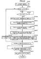
- the control unit 2 estimates an in-cylinder temperature of each of the cylinders 12A to 12D based on a coolant temperature, a stop time-period (elapsed time after initiation of the automatic stop state), an intake-air temperature and/or other factor (Step S1101). In this way, the control unit 2 works as in-cylinder temperature estimating means. Then, the control unit 2 calculates an air volume in each of the stop-state compression-stroke cylinder 12A and the stop-state expansion-stroke cylinder 12B based on a detected stop position of the piston 13 thereof (Step S1102).
- a combustion chamber volume in each of the stop-state compression-stroke cylinder 12A and the stop-state expansion-stroke cylinder 12B is firstly calculated based on the stop position of the piston 13.
- the stop-state expansion-stroke cylinder 12B is also charged with fresh air because the engine crankshaft has several 360-degree rotations in a time period from the interruption of the fuel injection through until the engine is stopped, according to the automatic stop control, and each of the stop-state compression-stroke cylinder 12A and the stop-state expansion-stroke cylinder 12B has an in-cylinder pressure which is increased to approximately atmospheric pressure after the engine stop.
- the fresh air volume in each of the cylinders 12A, 12B can be calculated based on the calculated combustion-chamber volume.
- the control unit 2 determines whether a piston stop position of the stop-state compression-stroke cylinder 12A is located relatively closer to BDC in the non-assisted-combustion-restart enabling range R (60 to 80 CA degrees before TDC of the compression stroke) (Step S 1103).
- Step S1103 When the determination in Step S1103 is YES, i.e., when the value of the stop-range ID flag F ST is "1" and the calculated air volume is relatively large, the process advances to Step S1104.
- the control unit 2 operates to inject fuel into the stop-state compression-stroke cylinder 12A (this fuel injection will hereinafter be referred to as "1st fuel injection") in such a manner that an air-fuel mixture is formed at a given air-fuel ratio (e.g. about 20) equivalent to an excess air ratio ⁇ (air-fuel ratio/theoretical air-fuel ratio) > 1, with respect to the air volume of the stop-state compression-stroke cylinder 12A calculated in Step S1102.
- a given air-fuel ratio e.g. about 20
- This air-fuel ratio is derived from a 1st A/F map M1 for the stop-state compression-stroke cylinder 12A which is preset in association with piston stop position.
- the air-fuel mixture set at a lean air-fuel ratio ( ⁇ > 1) will never produce excessive combustion energy so as to prevent the piston 13 of the stop-state compression-stroke cylinder 12A from being excessively moved in the reverse rotation direction (i.e., from being moved beyond BDC and back to an intake stroke).
- Step S1105 the control unit 2 operates to inject fuel into the stop-state compression-stroke cylinder 12A (1st fuel injection) in such a manner that an air-fuel mixture is formed at a given air-fuel ratio equivalent to ⁇ ⁇ 1, with respect to the air volume of the stop-state compression-stroke cylinder 12A calculated in Step S1102.
- This air-fuel ratio is derived from a 1st A/F map M2 for the stop-state compression-stroke cylinder 12A which is preset in association with piston stop position.
- Step S1106 the control unit 2 operates to carry out ignition for the stop-state compression-stroke cylinder 12A at a timing when a given time determined in consideration of a time period required for the injected fuel to be vaporized (vaporization time) has elapsed from the 1st fuel injection. Then, based on whether an edge of a detection signal from the crank angle sensor 30 or 31 (a rising or falling edge of a crank angle signal therefrom) is detected within a predetermined time T LT after the ignition, the control unit 2 determines whether the piston 13 is moved (Step S1107).
- Step S1107 When the determination in Step S1107 is YES, i.e., it is determined that the piston 13 is moved, the control unit 2 updates the reverse-rotation ID flag F REV to "1" (Step S1108), and then the process advances to a next step.
- Step S1107 determines whether an elapsed time T after the ignition (post-ignition time) is less than the predetermined time T LT (Step S1109). If the determination in Step S1109 is YES, a re-ignition will be repeatedly carried out for the stop-state compression-stroke cylinder 12A (Step S1110).
- Step S1111 When the post-ignition time T exceeds the predetermined time T LT in Step S1109, the control unit 2 updates the reverse-rotation ID flag F REV to "2" (Step S1111), and then the process shifts to a starting normal-rotation control subroutine S220 in the assisted-combustion restart control subroutine S120.
- Step S1107 the control unit 2 calculates a split ratio [between a preceding (primary) fuel injection and a subsequent (secondary) fuel injection] in a split fuel injection for the stop-state expansion-stroke cylinder 12B (Step S1112).
- a percentage of the subsequent fuel injection is increased as the piston stop position of the stop-state expansion-stroke cylinder 12B is located closer to BDC, and the in-cylinder temperature is higher.
- control unit 2 calculates a total fuel injection amount for the stop-state expansion-stroke cylinder 12B in such a manner that an air-fuel mixture is formed at a given air-fuel ratio ( ⁇ ⁇ 1) with respect to the air volume of the stop-state expansion-stroke cylinder 12B calculated in Step S1102 (Step S1113).
- This air-fuel ratio is derived from an A/F map M3 which is preset in association with piston stop position.
- control unit 2 calculates a preceding (primary) fuel injection amount for the stop-state expansion-stroke cylinder 12B, and operates to inject fuel in the calculated amount (Step S1114).
- Step S1115 the control unit 2 calculates a subsequent (secondary) fuel injection timing for the stop-state expansion-stroke cylinder 12B (Step S1115).
- This secondary fuel injection timing is set at a timing which allows a compression pressure of the in-cylinder air being compressed after the piston 13 of the stop-state expansion-stroke cylinder 12B starts being moved toward TDC (in the reverse rotation direction), to be effectively lowered by a latent heat of vaporization of injected fuel in the secondary fuel injection (i.e., allow the piston 13 to be moved possibly closer to TDC), while allowing a vaporization time for the injected fuel before the injection timing to be maximized.
- the control unit 2 calculates a fuel injection amount at the secondary fuel injection timing calculated in Step S1115, and instructs the fuel injection valve 16 to inject fuel in the calculated amount (Step S1116).
- the control unit 2 operates to activate the spark plug 15 at a timing after an elapse of a predetermined delay time (Steps S1117, S1118).
- the predetermined delay time is derived from an ignition delay map M4 for the stop-state expansion-stroke cylinder 12B which is preset in association with piston stop position. According to initial combustion induced in the stop-state expansion-stroke cylinder 12B by this ignition, the engine rotation is changed from the reverse direction to the normal direction.
- the piston 13 of the stop-state compression-stroke cylinder 12A starts being moved toward TDC to compress in-cylinder gas (burnt gas as a product of the combustion induced by the ignition in Step S1106).
- Step S1118 After the ignition for the stop-state expansion-stroke cylinder 12B in Step S1118, the control unit 2 operates to carry out ignition once again. Then, based on whether an edge of a detection signal from the crank angle sensor 30 or 31 (a rising or falling edge of a crank angle signal therefrom) is detected within a predetermined time T LT after the second ignition, the control unit 2 determines whether the piston 13 is moved (Step S1119). When the determination in Step S1119 is YES, i.e., it is determined that the piston 13 is moved, the control unit 2 sets the restart ID flag F RS to "01" (Step S1120), and then the process shifts to a next step.
- Step S1119 determines whether an elapsed time T after the ignition in Step S1118 is less than the predetermined time T LT (Step S1121). If the determination in Step S1121 is YES, a re-ignition will be repeatedly carried out for the stop-state expansion-stroke cylinder 12B (Step S1122).
- Step S1121 When the post-ignition time T exceeds the predetermined time T LT in Step S1121, the control unit 2 sets the restart ID flag F RS to "02" (Step S1123), and then the process shifts to the starting normal-rotation control subroutine S220 in the assisted-combustion restart control subroutine S120.
- Step S1119 when the determination in Step S1119 is YES, i.e., it is determined that the piston 13 is moved, the control unit 2 instructs the fuel injection valve 16 to inject 2nd fuel into the stop-state compression-stroke cylinder 12A in an amount determined in consideration with a vaporization time of injected fuel (Step S1124).
- This fuel injection amount is derived from a 2nd A/F map M5 for the stop-state compression-stroke cylinder 12A, which is preset in association with piston position, in such a manner that an overall air-fuel ratio based on a total fuel amount in the 1st and 2nd fuel injections becomes richer (e.g., about 6) than a combustible air-fuel ratio (lower limit value: 7 to 8).
- a latent heat of vaporization of the injected fuel in the 2nd fuel injection makes it possible to lower a compression pressure in the vicinity of TDC of the second compression stroke which is undergone by the stop-state compression-stroke cylinder 12A, so as to allow the stop-state compression-stroke cylinder 12A to readily overcome the first compression stroke, i.e., allow the piston 13 of the stop-state compression-stroke cylinder 12A to pass beyond TDC of the first compression stroke without difficulty.
- This 2nd fuel injection for the stop-state compression-stroke cylinder 12A is performed solely for the purpose of lowering the compression pressure therein, and therefore no ignition/combustion for the 2nd fuel injection is carried out (self-ignition never occurs because of the air-fuel mixture richer than the combustible air-fuel ratio).
- This incombustible air-fuel mixture will be purified through a reaction with oxygen stored in the catalyst 37 in the exhaust passage 22.
- Second combustion next to the initial combustion in the stop-state expansion-stroke cylinder 12B is carried out in the stop-state intake-stroke cylinder 12C, because the air-fuel mixture formed by the 2nd fuel injection for the stop-state compression-stroke cylinder 12A is not burnt, as described above.
- a part of energy of the initial combustion in the stop-state expansion-stroke cylinder 12B is used for allowing the stop-state intake-stroke cylinder 12C to overcome the second compression stroke, i.e., for allowing the piston 13 of the stop-state intake-stroke cylinder 12C to pass beyond TDC of the second compression stroke.
- the initial combustion energy in the stop-state expansion-stroke cylinder 12B is used both for allowing the piston 13 of the stop-state compression-stroke cylinder 12A to pass beyond the TDC of the first compression stroke and then allowing the piston 13 of the stop-state intake-stroke cylinder 12C to pass beyond TDC of the second compression stroke.
- the control unit 2 estimates an in-cylinder air density, and calculates an air volume in the stop-state intake-stroke cylinder 12C based on the estimate value (Step S1125). Then, based on the in-cylinder temperature estimated in Step S1101, the control unit 2 calculates an air-fuel-ratio correction value for preventing self-ignition (Step S1126). Specifically, if self-ignition occurs, resulting combustion will generate force (counter torque) which pushes back the piston 13 of the stop-state intake-stroke cylinder 12C toward BDC of the second compression stroke before the piston 13 reaches to TDC of the second compression stroke. This undesirably causes increased consumption of the energy for allowing the piston 13 to pass beyond TDC of the second compression stroke. With a view to avoiding this problem, an air-fuel ratio is corrected to a relatively lean side of a rich air-fuel ratio range so as to prevent the occurrence of self-ignition to suppress the counter torque.
- Step S1127 based on the air volume of the stop-state intake-stroke cylinder 12C calculated in Step S1125, and a target air-fuel ratio determined in consideration with the air-fuel-ratio correction value calculated in Step S1126, the control unit 2 calculates a fuel injection amount for the stop-state intake-stroke cylinder 12C (Step S1127).
- Step S1128 fuel is injected into the stop-state intake-stroke cylinder 12C.
- a timing of this fuel injection is delayed until a last stage of the second compression stroke to lower a compression pressure based on latent heat of vaporization of the injected fuel (i.e., to reduce energy required for passing beyond TDC of the second compression stroke) (Step S1128).
- the delay value is calculated based on a stop time-period (elapsed time after initiation of the automatic stop state of the engine), an intake-air temperature, an engine coolant temperature and/or other factor.
- Step S1119 the control unit 2 calculates a checkup timing on the basis of the timing when the edge of the signal from the crank angle sensor 30 or 31 (Step S1129), and keeps a standby state until the calculated checkup timing (Step S1130).
- Step S1131 determines whether the engine speed Ne at the calculated checkup timing (hereinafter referred to as "checkup engine speed Ne) is equal to or greater than a given required engine speed Ne (e.g., 200 rpm) (Step S1131).
- a given required engine speed Ne e.g. 200 rpm
- the control unit 2 determines that the piston of the stop-state intake-stroke cylinder 12C will pass beyond TDC of the second compression stroke, and updates the restart ID flag F RS to "11" (Step S1132).
- Step S1131 If the checkup engine speed Ne is less than the required engine speed Ne (the determination in Step S1131 is NO), the control unit 2 updates the restart ID flag F RS to "12" (Step S1133), and then the process shifts to the starting normal-rotation control subroutine S220 in the assisted-combustion restart control subroutine S120.
- Step S1134 when the piston of the stop-state intake-stroke cylinder 12C has passed beyond TDC of the second compression stroke, the control unit 2 updates the value of the restart ID flag F RS to "21" (Step S1135), and operates to activate the spark plug 15 at a given ignition timing (Step S1136).
- the control unit 2 updates the restart ID flag F RS to "22" (Step S1137), and then the process shifts to the starting normal-rotation control subroutine S220 in the assisted-combustion restart control subroutine S120.
- the ignition timing for the stop-state intake-stroke cylinder 12C is delayed until at or after TDC of the second compression stroke, so that suppress of counter torque occurs.
- the compression pressure thereof is lowered until the piston reaches TDC of the second compression stroke, to allow the piston to easily pass beyond TDC of the second compression stroke, and torque based on combustion energy is generated in a normal rotation direction at a timing after TDC.
- the stop-state exhaust-stroke cylinder 12D will undergo a compression stroke which occurs third after initiation of the automatic restart control (i.e., third compression stroke).
- the process returns to the main routine to inject fuel in the intake stroke according to a normal engine control, and carry out ignition before passing beyond TDC of the third compression stroke so as to obtain high torque.
- assisted-combustion restart control subroutine will be described below.
- the control unit 2 refers to the stored stop-range ID flag F ST (Step S1201).
- the control unit 2 executes a starting reverse-rotation control subroutine (Step S210).
- This starting reverse-rotation control subroutine S210 is configured to reversely rotate the engine 1 before normally rotating the engine 1.
- Step S1111 the content of the starting reverse-rotation control subroutine S210 is substantially the same as that (Steps S1101 to S1106, and S1108) of the aforementioned combustion-based restart control subroutine S110, and therefore its detailed description will be omitted.
- the control unit 2 estimates an in-cylinder temperature based on an engine coolant temperature, a stop time-period (elapsed time after initiation of the automatic stop state of the engine), an intake-air temperature, and/or other factor (Step S1202), and then determines whether the estimated in-cylinder temperature is equal to or greater than a given value, i.e., whether an operational state of the engine 1 is warmed-up or cold-start (Step S1203). If it is determined in Step S1203 is in warmed-up, the control unit 2 further refers to the stored stop-range ID flag F ST (Step S1204).
- Step S200 the control unit 2 executes a piston-position correction control subroutine
- Step S220 the starting normal-rotation control subroutine
- Step S1203 When it is determined in Step S1203 that the operational state of the engine 1 is in warmed-up or it is determined in Step S1204 that the stop-range ID flag F ST is any one of "3", "4" and "5", the control unit 2 skips the piston-position correction control subroutine S200, and executes the starting normal-rotation control subroutine S220.
- control unit 2 sets a fuel injection amount for the stop-state expansion-stroke cylinder 12B, depending on piston stop position based on a control map M20 (Step S2001).
- Step S2002 the control unit 2 operates to inject fuel into the stop-state expansion-stroke cylinder 12B (Step S2002). After an elapse of a given time set in consideration of a vaporization time of the injected fuel, and the control unit 2 operates to carry out ignition for the stop-state expansion-stroke cylinder 12B (Step S2003). In this process, multi-spark ignition is carried out to increase a combustion speed in the stop-state expansion-stroke cylinder 12B. For this purpose, it is determined whether a counted number of sparks N Ig reaches a required number of sparks N Ig_end (Step S2005) in this embodiment.
- Step S2006 ignition will be carried out one again (Step S2006), and the then process will return to Step S2004.
- Step S2007 it is determined whether the piston 13 is moved to an adequate range, based on whether an edge of a detection signal from the crank angle sensor 30 or 31 (a rising or falling edge of a crank angle signal therefrom) is detected within the predetermined time T LT after the last ignition (Step S2007). If the determination in Step S2007 is YES, the value of the correction ID flag F EXP will be changed to "1", and then the process will return to the main routine.
- Step S2007 determines whether an elapsed time T after the ignition is equal to or less than the given time T LT after the ignition (Step S2009). If the elapsed time T is equal to or less than the given time T LT , ignition will be repeatedly carried out for the stop-state expansion-stroke cylinder 12B (Step S2010). When the elapsed time T after the ignition becomes greater than the given time T LT , the control unit 2 changes the value of the correction ID flag F EXP to "2" (Step S2011), and then process returns to the main routine.
- a starter-motor drive control subroutine S240 will be executed concurrently therewith.
- the control unit 2 determines whether combustion in the stop-state expansion-stroke cylinder 12B can be utilized for this normal-rotation control process (Step S2201). Specifically, the control unit 2 refers to the stored stop-range ID flag F ST . When the stop-range ID flag F ST is any one of "1", "3" and "4", the process will advance to Step S2202. If the stop-range ID flag F ST has a value other than "1", "3” and "4", the control, unit 2 will cease combustion in each of the stop-state expansion-stroke cylinder 12B and the stop-state intake-stroke cylinder 12C (Steps S2203 and S2206).
- Step S2203 Even when combustion in the stop-state expansion-stroke cylinder 12B is ceased in Step S2203, the control unit 2 refers to the reverse-rotation ID flag F REV to determine whether the reverse-rotation ID flag F REV has a value other than "2" (Step S2204).
- self-ignition is likely to occur in the stop-state compression-stroke cylinder 12A.
- Step S2204 when the reverse-rotation ID flag F REV is "2" in Step S2204, even though combustion in the stop-state expansion-stroke cylinder 12B is ceased, additional fuel is injected into the stop-state compression-stroke cylinder 12A to provide an overrich air-fuel ratio in the stop-state compression-stroke cylinder 12A so as to prevent the occurrence of self-ignition.
- Step S 2201 If the stop-range ID flag F ST is "1" in Step S 2201, it can be estimated that the piston 13 is stopped within the non-assisted-combustion-restart enabling range R after completion of the automatic stop control. Thus, in this normal-rotation control process, combustion in the stop-state expansion-stroke cylinder 12B has to be produced to move the piston 13 in the normal rotation direction under the condition that the piston 13 is located at the current position without performing the reverse rotation operation. If the stop-range ID flag F ST is "3", it can be estimated that the piston 13 is stopped within the assisted-combustion-restart enabling range A2. Thus, effective combustion in the stop-state expansion-stroke cylinder 12B can be obtained while driving the engine 1 by the starter motor 36.
- stop-range ID flag F ST is "4", it can be estimated that the piston 13 is stopped within the combustion-restart disenabling range NG1.
- effective combustion can be produced in the stop-state expansion-stroke cylinder 12B.
- fuel is injected into the stop-state expansion-stroke cylinder 12B in response to satisfaction of additional conditions, to obtain torque based on combustion therein.
- Step S200 if the stop-range ID flag F ST is "2" in Step S2201, it can be estimated that the engine 1 has been subjected to the aforementioned piston-position correction control subroutine (Step S200). Thus, in this case, no combustion is produced in the stop-state expansion-stroke cylinder 12B. If the stop-range ID flag F ST is "5", it can be estimated that the piston 13 is stopped with the range of ⁇ 0 to ⁇ 1 illustrated in FIG 4. Thus, even if fuel is injected into the stop-state expansion-stroke cylinder 12B, the exhaust valve 20 will be opened before volatilization/atomization of the injected fuel to preclude desired torque from being obtained. Therefore, as with the above case, no combustion is produced in the stop-state expansion-stroke cylinder 12B to avoid useless fuel injection/ignition.
- Step S2201 when the stop-range ID flag F ST is any one of "1", “3" and "4" in Step S2201, the control unit 2 refers to the stored restart ID flag F RS (Step S2202). Given that the stop-range ID flag F ST has a value other than "0" in Step S2202, it can be estimated that combustion has already been produced in the stop-state expansion-stroke cylinder 12B, or misfire has occurred therein. In the stop-state expansion-stroke cylinder 12B which has already been subjected to combustion, even if fuel is injected thereinto, desired torque cannot be generated from combustion due to lack of fresh air therein.
- Step S2202 When the determination in Step S2202 is YES, a combustion control subroutine S230 for the stop-state expansion-stroke cylinder 12B will be executed. If the determination in Step S2202 is NO, combustion in the stop-state expansion-stroke cylinder 12B will be ceased. Except that the fuel injection timing is set at a timing after the piston 13 is driven by the starter motor 36, and the steps for allowing the starter motor 36 to be used in combination are omitted (such as Step S1123), the content of the combustion control subroutine S230 to be executed is substantially the same as the fuel injection control for the stop-state expansion-stroke cylinder 12B illustrated in FIG. 15, and therefore its detailed description will be omitted.
- Step S230 When the Step S230 is executed, or the reverse-rotation ID flag F REV is "2" in Step S2204, the control unit 2 operates to inject fuel into the stop-state compression-stroke cylinder 12A in consideration of a vaporization/atomization of the fuel (Step S2207).
- An air-fuel ratio to be formed by this fuel injection is derived from a 2nd A/F map M30 for the stop-state compression-stroke cylinder 12A, which is preset in association with piston position.
- Step S2206 when the fuel injection for the stop-state compression-stroke cylinder 12A is ceased in Step S2206, the control unit 2 refers to the stored restart ID flag F RS (Step S2208). If the restart ID flag F RS is "12" or "22”, the control unit 2 further ceases fuel injection for the stop-state intake-stroke cylinder 12C (Step S2209). The reason is that the value "12" or "22" of restart ID flag F RS means a completion of fuel injection in the stop-state intake-stroke cylinder 12C.
- Step S2207 when Step S2207 is executed to inject fuel into the stop-state compression-stroke cylinder 12A, or it is determined in Step S2208 that fuel injection for the stop-state intake-stroke cylinder 12C has not been performed, the control unit 2 estimates an in-cylinder air density in the stop-state intake-stroke cylinder 12C, and calculates an air volume in the stop-state intake-stroke cylinder 12C based on the estimate value (Step S2220). Then, based on the in-cylinder temperature, the control unit 2 calculates an air-fuel-ratio correction value for preventing self-ignition (Step S2221).
- Step S2222 based on the air volume of the stop-state intake-stroke cylinder 12C calculated in Step S2220, and a target air-fuel ratio determined in consideration with the air-fuel-ratio correction value calculated in Step S2221, the control unit 2 calculates a fuel injection amount for the stop-state intake-stroke cylinder 12C (Step S2222).
- Step S2223 and S2224 fuel is injected into the stop-state intake-stroke cylinder 12C.
- a timing of this fuel injection is delayed until a last stage of the second compression stroke to lower a compression pressure based on latent heat of vaporization of the injected fuel (Steps S2223 and S2224).
- the delay value is calculated based on a stop time-period (elapsed time after initiation of the automatic stop state of the engine), an intake-air temperature, an engine coolant temperature and/or other factor.
- the control unit 2 refers to the restart ID flag F RS , and determines whether the restart ID flag F RS is "22". If the restart ID flag F RS is "22" at a time when the stop-state intake-stroke cylinder 12C undergoes the second compression stroke, it can be estimated that the stop-state intake-stroke cylinder 12C has already been subjected to the restart control in the combustion-based restart control subroutine S110, and has failed to pass beyond TDC of the second compression stroke (see FIG. 17). In this case, it is necessary to take measures against self-ignition in the stop-state intake-stroke cylinder 12C having the highest possibility of occurrence of self-ignition.
- the control system is designed while taking account of influences of the engine speed. Specifically, in a relatively low engine speed range, a heat conduction time becomes longer, and thereby an in-cylinder temperature of the stop-state intake-stroke cylinder 12C becomes higher during a hot-restart operation. Thus, even if the fuel injection timing is delayed as described above, self-ignition is still likely to occur therein.
- a map M14 prepared by correlating a cranking air-fuel ratio with the engine speed is stored in the memory of the control unit 2. Then, an injection amount of additional fuel is set with reference to the map M14, to allow an air-fuel mixture to become richer depending on the engine speed Ne (Step S2226), and a timing of engagement between the ring gear 35 and the pinion gear 36d of the starter motor 36 is detected (Step S2227). Then, the additional fuel is injected into the stop-state intake-stroke cylinder 12C at the detected engagement timing (Step S2228).
- the timing when the pinion gear 36d of the starter motor 36 engages with the ring gear 35 corresponds to a time point immediately after the engine speed Ne is reduced to zero in a course of reverse rotation of the crankshaft 3 due to the piston 13 which has failed to pass beyond TDC, as described in detail later.
- This fuel injection timing makes it possible to facilitate vaporization/atomization of the injected additional fuel so as to avoid the occurrence of self-ignition.
- Step S2229 it is determined whether the piston of the stop-state intake-stroke cylinder 12C passes beyond TDC of the second compression stroke. If the piston of the stop-state intake-stroke cylinder 12S passes beyond TDC of the second compression stroke, ignition is carried out for the stop-state intake-stroke cylinder 12C (Step S2230), and then the process returns to the original routine.
- Step S220 the assisted-combustion restart or starting normal-rotation control subroutine
- Table 2 Flag State Operation Cylinder 12A Cylinder 12B Cylinder 12C
- Step S1123 in FIG 15 it can be estimated that combustion in the stop-state expansion-stroke cylinder 12B has resulted in failure (Step S1123 in FIG 15).
- fuel injection for the stop-state expansion-stroke cylinder 12B is ceased.
- additional fuel is injected into the stop-state compression-stroke cylinder 12A to lower an in-cylinder pressure during the restart operation based on the starter 36, and fuel injection is carried out for the stop-state intake-stroke cylinder 12C.
- Step S2202 in FIG 20 fuel injection for each of the stop-state expansion-stroke cylinder 12B and the stop-state compression-stroke cylinder 12A is ceased. Further, according to the determination in Step S2208, fuel injection for each of the stop-state intake-stroke cylinder 12C is also ceased (see FIG 20).
- Step S1133 in FIG 16 combustion in the stop-state expansion-stroke cylinder 12B has been completed, and fuel injection for each of the stop-state compression-stroke cylinder 12A and the stop-state intake-stroke cylinder 12C has already been done.
- Step S2202 in FIG. 20 fuel injection for each of the stop-state expansion-stroke cylinder 12B and the stop-state compression-stroke cylinder 12A is ceased.
- Step S2208 fuel injection for each of the stop-state intake-stroke cylinder 12C 12C also ceased.
- Step S240 when the starter-motor drive control subroutine S240 is executed, a current value of the engine speed Ne is detected, and it is determined whether the detected engine speed Ne is zero (Step S2410). If the detected engine speed Ne is zero, the control unit 2 will immediately determine a timing tout of driving the starter motor 36 (Step S2402).
- the controller 2 stands ready to detect a crank angle CA0 at which the engine speed Ne initially becomes zero after lowering (see FIG. 23). Then, on the basis of the detected crank angle CA0 when the engine speed Ne becomes zero, the controller 2 then stands ready to detect a time when the engine speed Ne at the crank angle CA0 is lowered to at a value corresponding to a given crank angle CA1 (Step S2403).
- the control unit 2 sets the time T CA1 when the piston 13 is moved to a position corresponding to CA1, as a reference time point for calculation (Step S2404).
- the control unit 2 calculates a zero-speed time tp for the starter motor 36 when the engine speed Ne becomes zero after being changed from the reverse rotation direction to the normal rotation direction on the basis of the assist reference time T CA1 (Step S2405). Further, based on the zero-speed time tp, the control unit 2 calculates an engagement time range Ts for the starter motor 36 (Step S2406). This engagement time range Ts is determined based on specification data of the starter motor 36 which is prepared based on specifications of a starter motor employed as the starter motor 36, and pre-stored in a storage area of the control unit 2.
- the starter motor 36 is designed such that, when the ring gear 35 is stopped, the pinion gear 36d is engaged with the ring gear 35 while being rotationally driven by the drive motor 36a at about 60 rpm in a direction opposite to a rotation direction of the ring gear 35.
- the engagement time range Ts is set to allow the engagement to be performed when the engine speed Ne is in the range of zero to 60 rpm.
- a driving delay time-period Tdy of the starter motor 36 is calculated based on a buttery voltage (Step S2407).
- the pinion gear 36d is engaged with the ring gear 35 while being rotationally driven by drive motor 36a in the opposite direction to the rotation direction of the ring gear 35, as mentioned above.
- a certain time lag i.e., driving delay time-period Tdy
- a time tout is calculated in consideration of the driving delay time-period Tdy.
- Step S2407 the control unit 2 calculates the time tout based on the above calculation.
- the calculation in Step S2402 is performed on the assumption that the engine speed is zero.
- Step S2402 or Step S2408 the control unit 2 generates a drive signal at the time tout to drive the starter motor 36.
- the pinion gear 36d of the starter motor 36 is driven by the drive motor 36a and engaged with the ring gear 35, so that the crankshaft 3 is assisted by a driving force from the starter motor 36. Then, the process returns to the main routine.
- Step S2410 After the piston of the stop-state intake-stroke cylinder 12C passes beyond the second compression stroke, i.e., a compression stroke occurs second after initiation of the automatic stop state of the engine 1, based on the combustion-based restart control subroutine or the assisted-combustion restart control subroutine, it is determined whether the engine speed becomes equal to or greater than a given value (Step S2410). Then, in response to detection of the given engine speed, the driving of the starter motor 36 is released, and then the process is terminated (Step S2411).
- FIG 24 is a time chart showing a fuel injection timing to be set when misfire occurs in the top-state compression-stroke cylinder 12A during the reverse-rotation operation.
- Step S1111 in FIG. 14 when it is determined that combustion failure occurs in the stop-state compression-stroke cylinder 12A after ignition during the reverse-rotation operation (when Step S1111 in FIG. 14 is executed, and the reverse-rotation ID flag F REV is updated to "2"), the subroutine in FIG. 20 is executed, and the starter motor 36 is activated to drive the engine 1 in the normal rotation direction.
- the stop-state compression-stroke cylinder 12A determined that it has had combustion failure is susceptible to self-ignition due to an increase in in-cylinder pressure and unburnt fuel remaining therein.
- combustion is produced in the stop-state expansion-stroke cylinder 12B (Step S230), and additional fuel is injected into the stop-state compression-stroke cylinder 12A in Step S2201 in FIG 20, which undergoes the first compression stroke and having an in-cylinder pressure being gradually increasing, so as to facilitate lowering the in-cylinder pressure based on a latent heat in the cylinder and allow an air-fuel ratio to become overrich to reliably avoid self-ignition in the end gas in the combustion chamber.
- the fuel injection control means or the control unit 2 is operable to interrupt fuel injection for the stop-state expansion-stroke cylinder.
- an in-cylinder pressure of the stop-state expansion-stroke cylinder is kept approximately at atmospheric pressure.
- fuel injection for the stop-state expansion-stroke cylinder can be interrupted to suppress deterioration in emission performance.
- control unit 2 is provided as in-cylinder temperature estimating means adapted to estimate an in-cylinder temperature of each of the cylinders 12A to 12D at least during stop of the engine 1.
- This control unit 2 is operable to adjust an injection amount of the additional fuel in such a manner as to provide a higher air-fuel ratio as the estimated in-cylinder temperature of the stop-state compression-stroke cylinder is higher.
- an amount of fuel to be injected as the additional fuel i.e., an air-fuel ratio to be determined by the additional fuel, can be adjusted depending on an in-cylinder temperature of the stop-state compression-stroke cylinder 12A to optimally prevent the air-fuel ratio in the stop-state compression-stroke cylinder from becoming excessively rich so as to maintain adequate emission performance.
- the control unit 2 is adapted to determine that the in-cylinder temperature is higher as an elapsed time after initiation of the automatic stop state of the engine 1 is closer to a given value which is equal to or less than 60 seconds. Based on inventers' knowledge that a charged-air temperature in the cylinder of the engine 1 is rapidly increased within a given elapsed time after initiation of the automatic stop state of the engine 1, which is equal to or less than 60 seconds, the control unit 2 is configured to adjust the injection amount of the additional fuel in such a manner as to provide a higher air-fuel ratio as a timing of the satisfaction of the restart condition is closer to the given time. This makes it possible to reliably prevent the occurrence of knocking under temperature conditions which are highly likely to cause self-ignition.
- the engine control system has a significant advantage of being able to reliably prevent the occurrence of self-ignition and warm-start lock in the stop-state compression-stroke cylinder 12A during a process of achieving a fail-safe function based on the starter motor 36.
Abstract
Description
- The present invention relates to a multi-cylinder four-cycle engine control system, and more particularly to a multi-cylinder four-cycle engine control system suitable for an automatic stop system using motor-operated drive means.
- There has been known an engine control system (automatic stop system) designed to automatically stop an engine during idling for the purpose of reductions in fuel consumption and CO2 emissions, as disclosed, for example, in the
Japanese Patent Laid-Open Publication No. 2004-124753 - In this automatic stop system, there are two types of restart processes: a normal-rotation restart process designed to produce combustion in a stop-state expansion-stroke cylinder immediately after satisfaction of a restart condition so as to normally rotate the engine (rotate an engine in a normal direction); and a reverse-rotation restart process designed to produce combustion in a stop-state compression-stroke cylinder in response to satisfaction of a restart condition so as to reversely rotate the engine (rotate an engine in a reverse direction) and then produce combustion in a stop-state expansion-stroke cylinder so as to change the engine rotation direction (allow the engine to be rotated in the normal direction). The reverse-rotation restart process has an advantage of being able to generate high starting torque and enhance starting stability and quick response, because combustion of an air-fuel mixture in a stop-state expansion-stroke cylinder can be produced after an in-cylinder pressure of the stop-state expansion-stroke cylinder is increased, as disclosed, for example, in the
Patent Document 1. - Additionally, in the above reverse-rotation restart-type automatic stop system, even in the event of failure in producing combustion in a stop-state compression-stroke cylinder, the restart process can be advantageously continued by use of motor-operated drive means in combination.
- In reality, if misfire occurs in a stop-state compression-stroke cylinder, fuel injected into the stop-state compression-stroke cylinder would be remained as unburnt fuel. Thus, when the motor-operated drive means is activated to restart the engine, self-ignition is likely to occur in the stop-state compression-stroke cylinder and cause knocking.
- In view of the above problem, it is an object of the present invention to provide a multi-cylinder four-cycle engine control system capable of reliably preventing the occurrence of self-ignition in a stop-state compression-stroke cylinder to enhance starting stability, during a process of achieving a fail-safe function based on motor-operated drive means.
- In order to achieve the above object, the present invention provides a control system for a multi-cylinder four-cycle engine, which is designed to, when a condition for restarting the engine in an automatic stop state is satisfied, produce combustion in a stop-state compression-stroke cylinder so as to reversely rotate the engine by a given crank angle, and then produce combustion in a stop-state expansion-stroke cylinder so as to normally rotate the engine to restart the engine. This control system is characterized by motor-operated drive means adapted to assist in starting the engine in its stop state, operational-state determination means adapted to determine an operational state of the engine, ignition control means adapted, based on the determination result of the operational-state determination means, to execute ignition in each of the cylinders at a given timing, combustion-completeness determination means adapted to determine completeness of combustion in the cylinder having the ignition executed by the ignition control means, motor-operated-drive control means adapted, when the combustion-completeness determination means determines that the combustion in the stop-state compression-stroke cylinder is failed, to activate the motor-operated drive means, and fuel-injection control means adapted, when the motor-operated drive means is activated in response to the combustion failure as the determination result of the combustion-completeness determination means, to inject an additional fuel into the stop-state compression-stroke cylinder at an intermediate timing of a first-undergoing compression stroke thereof after the activation of the motor-operated drive means.
- In the above control system of the present invention, after ignition in the stop-state compression-stroke cylinder during the reverse-rotation restart process, when combustion in the stop-state compression-stroke cylinder is determined to have failed, the motor-operated drive means is activated, and the engine is driven in a normal rotation direction by the motor-operated drive means. While the stop-state compression-stroke cylinder determined that a combustion failure occurs therein is susceptible to self-ignition due to unburnt fuel remaining therein and an increase in in-cylinder pressure caused by the drive in the normal rotation, the spontaneous ignition of the end gas can be reliably avoided by injecting the additional fuel into the stop-state compression-stroke cylinder during a course of the increase in in-cylinder pressure to facilitate lowering the in-cylinder pressure based on a latent heat of vaporization of the injected fuel and allow an air-fuel ratio to become overrich.
- In a preferred embodiment, the fuel-injection control means is operable, when the motor-operated drive means is activated in response to the combustion failure as the determination result of the combustion-completeness determination means, to interrupt fuel injection for the stop-state expansion-stroke cylinder.
- When combustion in the stop-state compression-stroke cylinder is incomplete, an in-cylinder pressure of the stop-state expansion-stroke cylinder is kept approximately at atmospheric pressure. Thus, according to this preferred embodiment, fuel injection for the stop-state expansion-stroke cylinder having an in-cylinder pressure kept at a low value can be interrupted to suppress deterioration in emission performance.
- In a preferred embodiment, the control system further includes in-cylinder temperature estimating means adapted to estimate an in-cylinder temperature of each of the cylinders at least during stop of the engine, and the fuel-injection control means is operable to adjust an injection amount of the additional fuel in such a manner as to provide a higher air-fuel ratio as the estimated in-cylinder temperature of the stop-state compression-stroke cylinder is higher.
- According to this preferred embodiment, an amount of fuel to be injected as the additional fuel, i.e., an air-fuel ratio to be determined by the additional fuel, can be adjusted depending on an in-cylinder temperature of the stop-state compression-stroke cylinder to optimally prevent the air-fuel ratio in the stop-state compression-stroke cylinder from becoming excessively rich so as to maintain adequate emission performance.
- In a preferred embodiment, the in-cylinder temperature estimating means is adapted to determine that the in-cylinder temperature is higher as an elapsed time after initiation of the automatic stop state of the engine is closer to a given value which is equal to or less than 60 seconds.
- According to this preferred embodiment, based on inventers' knowledge that a charged-air temperature in the cylinder is rapidly increased within a given elapsed time after initiation of the automatic stop state of the engine, which is equal to or less than 60 seconds, the fuel-injection control means is configured to adjust the injection amount of the additional fuel in such a manner as to provide a higher air-fuel ratio as a timing of the satisfaction of the restart condition is closer to the given time. This makes it possible to reliably prevent the occurrence of knocking under temperature conditions which are highly likely to cause self-ignition.
- In a preferred embodiment, the above control system includes a coolant temperature sensor adapted to detect a temperature of coolant of the engine, and the in-cylinder temperature estimating means is adapted to estimate the in-cylinder temperature based on the detection result of the coolant temperature sensor.
- In a preferred embodiment, the above control system includes an intake-air temperature sensor adapted to detect a temperature of intake air of the engine, and the in-cylinder temperature estimating means is adapted to estimate the in-cylinder temperature based on the detection result of the intake-air temperature sensor.
- This control system is characterized by motor-operated drive means adapted to assist in starting the engine in its stop state, operational-state determination means adapted to determine an operational state of the engine, ignition control means adapted, based on the determination result of the operational-state determination means, to execute ignition in each of the cylinders at a given timing, combustion-completeness determination means adapted to determine completeness of combustion in the cylinder having the ignition executed by the ignition control means, motor-operated-drive control means adapted, when the combustion-completeness determination means determines that the combustion in the stop-state compression-stroke cylinder is failed, to activate the motor-operated drive means, and fuel-injection control means adapted, when the motor-operated drive means is activated in response to the combustion failure as the determination result of the combustion-completeness determination means, to inject an additional fuel into the stop-state compression-stroke cylinder at an intermediate timing of a first-undergoing compression stroke thereof after the activation of the motor-operated drive means.
- In the above control system of the present invention, after ignition in the stop-state compression-stroke cylinder during the reverse-rotation restart process, when combustion in the stop-state compression-stroke cylinder is determined to have failed, the motor-operated drive means is activated, and the engine is driven in a normal rotation direction by the motor-operated drive means. While the stop-state compression-stroke cylinder determined that a combustion failure occurs therein is susceptible to self-ignition due to unburnt fuel remaining therein and an increase in in-cylinder pressure caused by the drive in the normal rotation, the spontaneous ignition of the end gas can be reliably avoided by injecting the additional fuel into the stop-state compression-stroke cylinder during a course of the increase in in-cylinder pressure to facilitate lowering the in-cylinder pressure based on a latent heat of vaporization of the injected fuel and allow an air-fuel ratio to become over rich.
- These and other objects, features and advantages of the invention will become more apparent upon reading the following detailed description along with the accompanying drawings, in which:
- FIG 1 is a schematic block diagram of an engine control system according to one embodiment of the present invention;
- FIG 2 is a schematic diagram showing the structure of an intake system and an exhaust system of an engine equipped with the engine control system;
- FIG 3 is a schematic, partially-broken-away, sectional view showing the structure of a starter motor;
- FIG 4 is a schematic diagram showing appropriateness for a piston stop range during automatic stop;
- FIG. 5 is an explanatory diagram showing a relationship between a piston stop position and an air volume in each of a stop-state expansion-stroke cylinder and a stop-state compression-stroke cylinder during an automatic engine stop control;
- FIG 6 is an explanatory diagram schematically showing changes of an engine speed, a crank angle, a throttle opening and an intake pressure during the automatic engine stop control;
- FIG 7 is a distribution chart showing a correlation between an engine speed at TDC of a compression stroke during the automatic engine stop control and a piston stop position in an automatic stop state;
- FIG. 8 is a flowchart showing an automatic stop control process;
- FIG 9 is a flowchart showing the automatic stop control process;
- FIG 10 is a graph showing a relationship between an in-cylinder temperature and an elapsed time from initiation of the automatic stop state, wherein a curve of the in-cylinder temperature is based on an estimate value on the assumption that the in-cylinder temperature at the initiation of the automatic stop state is 80°C;
- FIG 11 is a graph showing a relationship between a self-ignition occurrence timing and a piston stop position in a stop-state compression-stroke cylinder;
- FIGS. 12A to 12D are schematic diagrams showing an automatic engine restart control process in the engine control system;
- FIG 13 is a flowchart showing a main routine of the restart control process;
- FIG 14 is a flowchart showing a combustion-based restart control subroutine;
- FIG 15 is a flowchart showing the combustion-based restart control subroutine;
- FIG 16 is a flowchart showing the combustion-based restart control subroutine;
- FIG 17 is a flowchart showing the combustion-based restart control subroutine;
- FIG 18 is a flowchart showing an assisted-combustion restart control subroutine;
- FIG 19 is a flowchart showing a piston-position correction control subroutine;
- FIG 20 is a flowchart showing a starting normal-rotation control subroutine;
- FIG 21 is a flowchart showing a starting reverse-rotation control subroutine;
- FIG 22 is a flowchart showing a starter-motor drive control subroutine;
- FIG 23 is a time chart showing changes in engine speed during execution of the subroutine in FIG 22; and
- FIG 24 is a timing chart showing a fuel injection timing to be used when misfire occurs in a stop-state compression-stroke cylinder during reverse rotation.
- Referring to FIGS. 1 and 2, an engine control system according to one embodiment of the present invention comprises a control unit (ECU) 2 for controlling an
engine 1 which includes acylinder head 10 and acylinder block 11. - The
engine 1 has fourcylinders 12A to 12D. As shown in FIG 1, apiston 13 connected to acrankshaft 3 is slidably inserted into each of thecylinders 12A to 12D in such a manner that acombustion chamber 14 is defined inside each of thecylinders 12A to 12D and above thepiston 12. - Typically, a multi-cylinder four-cycle engine is designed to carry out a combustion cycle consisting of intake, compression, expansion and exhaust strokes with a given phase difference therebetween. In this embodiment, given that the four cylinders are referred to respectively as "
1st cylinder 12A", "2nd cylinder 12B", "3rd cylinder 12C" and "4th cylinder 12D" from one end of cylinder arrangement, the four-cylinder engine is designed to carry out combustion in the 1st cylinder (#1), the 3rd cylinder (#3), the 4th cylinder (#4) and the 2nd cylinder (#2) in this order with a phase difference of 180 crank angle (CA) degrees therebetween. Further, in this embodiment, a cylinder on a compression stroke in an automatic stop state of the engine, will be referred to as "stop-state compression-stroke cylinder", and a cylinder on an expansion stroke in the automatic stop state of the engine will be referred to as "stop-state expansion-stroke cylinder". In the same manner, a cylinder on an intake stroke in the automatic stop state of the engine will be referred to as "stop-state intake-stroke cylinder", and a cylinder on an exhaust stroke in the automatic stop state of the engine will be referred to as "stop-state exhaust-stroke cylinder". - Referring to FIG 1, a
spark plug 15 is installed in thecylinder head 10 at a position corresponding to a top of thecombustion chamber 14 in each ofcylinders 12A to 12D to ignite and bum an air-fuel mixture in thecombustion chamber 14. Thespark plug 15 is disposed such that an electrode at a tip thereof is exposed to thecombustion chamber 14. Further, afuel injection valve 16 is installed in thecylinder head 10 on a lateral side (right side in FIG 1) of thecombustion chamber 14 in such a manner that a nozzle hole at a tip thereof is exposed to thecombustion chamber 14. Thisfuel injection valve 16 incorporates a needle valve and a solenoid (not shown). Specifically, thefuel injection valve 16 is adapted to be driven in response to input of a pulse signal from thecontrol unit 2 and opened only within a time period corresponding to a pulse width of the pulse signal so as to inject fuel directly into a corresponding one of thecylinders 12A to 12D in an amount corresponding to a driven time thereof. Further, thefuel injection valve 16 is so arranged that the fuel is injected toward a vicinity of theelectrode 15 of thespark plug 15. - Although not illustrated, the
fuel injection valve 16 is connected to a fuel pump via a fuel supply passage and others so as to be supplied with fuel from the fuel pump, and a fuel supply pressure thereof is set at a value greater than an inner pressure of thecombustion chamber 14 in a corresponding one of thecylinders 12A to 12D, so that fuel can be injected into thecombustion chamber 14 having a high inner pressure at and after an intermediate timing of a compression stroke in the cylinder. - An
intake port 17 and anexhaust port 18 are formed in thecylinder head 10 in such a manner as to be opened to an upper zone of thecombustion chamber 14 in each of thecylinders 12A to 12D. The intake andexhaust ports intake valve 19 and anexhaust valve 20, respectively. Theintake valve 19 and theexhaust valve 20 are adapted to be driven by a valve drive mechanism including a camshaft (not shown). Respective valve opening timings of theintake valve 19 and theexhaust valve 20 according to the valve drive mechanism are set to allow the combustion cycle to be carried out in each of thecylinders 12A to 12D with a given phase difference therebetween. - As shown in FIG. 2, the
intake port 17 and theexhaust port 18 communicate with anintake passage 21 and anexhaust passage 22, respectively. Theintake passage 21 has four branchedintake passages 21a on a downstream side, that is, on the side closer to theintake port 17, in a separated manner with respect to each of thecylinders 12A to 12D, and asurge tank 21b communicating with respective upstream ends of the branchedintake passages 21a. Further, on an upstream side of thesurge tank 21b, theintake passage 21 has acommon intake passage 21c for all of thecylinders 12A to 12D. Thecommon intake passage 21c is provided with athrottle valve 23 for adjusting a sectional area of thepassage 21c to restrict an intake-air flow, and anactuator 24 for moving thethrottle valve 23. Further, thecommon intake passage 21c is provided with anairflow sensor 25 for detecting an intake-air volume and anintake pressure sensor 26 for detecting an intake pressure (boost pressure; negative pressure), respectively, on upstream and downstream sides of thethrottle valve 23. - An
alternator 28 is disposed adjacent to theengine 1, and drivenly coupled to thecrankshaft 3 through a belt or the like. Thealternator 28 includes a built-inregulator circuit 28a for controlling a field coil current to change an output voltage so as to adjust an output power thereof. Fundamentally, thealternator 28 is operable to control the output power depending on an electric load of an electric component of a vehicle and a voltage of an in-vehicle battery, according to input of a control command (e.g., a voltage signal) from thecontrol unit 2. When the output power of thealternator 28 is changed in this manner, a driving force necessary for thealternator 28, i.e., a level of an external load to be imposed on theengine 1, will be changed. - As shown in FIGS. 1 and 2, a
catalyst 37 is disposed in theexhaust passage 22 on a downstream side of an exhaust manifold communicating with thecylinders 12A to 12D, to purify exhaust gas. For example, thecatalyst 37 is a so-called "three-way catalyst" which exhibits a significantly high conversion efficiency of HC, CO and NOx when an air-fuel ratio of exhaust gas is close to a theoretical air-fuel ratio, and has an oxygen absorbing/releasing capability of absorbing and storing oxygen in an oxygen-excess atmosphere where an oxygen concentration of exhaust gas is relatively high, and releasing the stored oxygen when the oxygen concentration is relatively low, to induce a reaction with HC, CO and other emission. Thecatalyst 37 is not limited to the three-way catalyst, but may be any other suitable catalyst having the above oxygen absorbing/releasing capability, such as a so-called "lean NOx catalyst" capable of removing NOx by reduction even in an oxygen-excess atmosphere. - The
engine 1 is provided with twocrank angle sensors crankshaft 3. Specifically, thecrank angle sensor 30 is adapted to generate a detection signal for use in detecting an engine speed Ne. Thecrank angle sensor 31 is adapted to generate a detection signal which is out of phase with that of thecrank angle sensor 30 so as to allow a rotation direction and a phase of thecrankshaft 3 to be detected based on the two detection signals. - The
engine 1 is further provided with acam angle sensor 32 for detecting a specific rotational position for cylinder identification, and a coolant temperature sensor 33 for detecting a temperature of engine coolant. A vehicle body is provided with anaccelerator angle sensor 34 for detecting an angle of an accelerator pedal corresponding to a displacement amount of the accelerator pedal based on a driver's action. - The
crankshaft 3 is provided with a flywheel (not shown) and aring gear 35 fixed to the flywheel, which are concentrically arranged with respect to the rotational axis of thecrankshaft 3. Thering gear 35 is provided as an input member for astarter motor 36 serving as motor-operated drive means, and designed to be engageable with an after-mentionedpinion gear 36d of thestarter motor 36. - Referring to FIG. 3, the
starter motor 36 includes adrive motor 36a, an electromagnetically-drivenplunger 36b disposed parallel to themotor 36a, and apinion gear 36d which is slidably fitted on an output shaft of themotor 36a in a non-rotatable manner relative to the output shaft, and adapted to be reciprocatingly moved along the output shaft by theplunger 36b through a shiftinglever 36c. More specifically, during restart of the engine, thestarter motor 36 is operable to move thepinion gear 36d from a standby position indicated by the solid line in FIG. 3 to an engagement position indicated by the two-dot chain line in FIG 3 in such a manner as to engage with thering gear 35 so as to rotationally drive thecrankshaft 3 to restart the engine. - The
pinion gear 36d of thestarter motor 36 employed in this embodiment has helically twisted teeth. Further, in order to facilitate engagement and disengagement with/from thering gear 35, thestarter motor 36 is designed to allow thepinion gear 36d to engage with thering gear 35 in its stop state while rotating at a speed of about 60 rpm in a direction opposite to a direction in which thering gear 35 is to be rotated. - Referring to FIG 1, the
control unit 2 is a microprocessor for comprehensively controlling an engine operation. The engine control system according to this embodiment is designed to perform a control (idling stop control or automatic stop control) for automatically stopping the engine by interrupting fuel injection (fuel cut) for each of thecylinders 12A to 12D at a given timing when a predetermined automatic stop condition is satisfied, and a control (combustion-based automatic restart control) for automatically restarting the engine in an automatic stop state when a predetermined automatic restart condition is satisfied, for example, when an accelerator pedal is depressed by a driver. For achieving these controls, thecontrol unit 2 is adapted to receive respective detection signals from theairflow sensor 25, theintake pressure sensor 26, the intake-air temperature sensor 29, thecrank angle sensors cam angle sensor 32, the coolant temperature sensor 33 and theaccelerator angle sensor 34, and output a drive signal to each of thefuel injection valves 16, theactuator 24 for thethrottle valve 23, anignition device 27 for the spark plugs 15, and theregulator circuit 28a of thealternator 28. In this manner, thecontrol unit 2 functionally makes up motor-operated-drive control means, operational-state determination means, in-cylinder temperature estimating means, stop-range identification means, stop-position correction means, fuel-injection control means and ignition control means. - Referring to FIGS. 4 and 5, a memory of the
control unit 2 stores a predetermined combustion-restart enabling range A which is defined by an upper limit of crank angle (CA) before TDC (Top Dead Center) or after TDC (i.e., θ1 in the stop-state compression-stroke cylinder 12A; θ4 in stop-state expansion-stroke cylinder 12B), and a lower limit of CA before TDC or after TDC (i.e., θ4 in the stop-state compression-stroke cylinder 12A; θ1 in stop-state expansion-stroke cylinder 12B). While thepiston 13 in each of thecylinders stroke cylinder 12A is preferably stopped within a range slightly closer to TDC relative to 90 CA degrees before TDC. In this embodiment, a range between 60 CA degrees before TDC and 80 CA degrees before TDC in the stop-state compression-stroke cylinder (in the stop-state expansion-stroke cylinder, a range between 100 CA degrees after TDC and 120 CA degrees after TDC), i.e., a range between θ2 and θ3 in FIG. 4, is defined as "non-assisted-combustion-restart enabling range R". Two ranges between a TDC-side limit of the non-assisted-combustion-restart enabling range R and θ1 in FIG. 4 and between a BDC (Bottom Dead Center)-side limit of the non-assisted-combustion-restart enabling range R and θ4 in FIG. 4, in the stop-state compression-stroke cylinder (in the stop-state expansion-stroke cylinder, two range between a BDC-side limit of the non-assisted-combustion-restart enabling range R and θ1 and between a TDC-side limit of the non-assisted-combustion-restart enabling range R and θ4) are defined, respectively, as "assisted-combustion-restart enabling range A2" and "assisted-combustion-restart enabling range A1". Further, the remaining two ranges are defined, respectively, as "combustion-restart disenabling range NG2" and "combustion-restart disenabling range NG1". These ranges are used as determination criteria by thecontrol unit 2. - The non-assisted-combustion-restart enabling range R means a range of piston stop position which enables the
engine 1 to be automatically restarted only by combustion without assistance of thestarter motor 36. Specifically, when thepiston 13 of the stop-state expansion-stroke cylinder is stopped within the non-assisted-combustion-restart enabling range R, an air volume in the stop-state expansion-stroke cylinder is maximized to allow combustion energy to be sufficiently produced. Further, during the automatic stop control, an opening degree K of thethrottle valve 23 is increased to facilitate scavenging while supplying a sufficient volume of fresh air to thecatalyst 37. Thus, in the automatic stop state, a sufficiently large amount of oxygen is stored in thecatalyst 37, and a desired air volume is ensured in the stop-state compression-stroke cylinder. Therefore, in the automatic restart control, when combustion is initially carried out in the stop-state compression-stroke cylinder, the stop-state compression-stroke cylinder can produce combustion energy for reversely rotating thecrankshaft 3 by a small angle. Then, the large air volume ensured in the stop-state expansion-stroke cylinder can produce sufficient combustion energy for normally rotating thecrankshaft 3 to reliably restart the engine. - For this purpose, in this embodiment, during the automatic stop control for automatically stopping the
engine 1, the fuel cut is initiated at a given engine speed slightly greater than an idling speed, and then thethrottle valve 23 is opened up to a predetermined opening degree for a given time period, so as to achieve sufficient scavenging in each of thecylinders 12A to 12D. Then, thethrottle valve 23 is closed at a predetermined appropriate timing. This makes it possible to sufficiently increase a volume of air to be charged in each of the two cylinders which will become the stop-state expansion-stroke cylinder 12B and the stop-state compression-stroke cylinder 12A (the two cylinders during an after-mentioned pre-stop period will hereinafter be referred to respectively as "pre-stop compression-stroke cylinder" and "pre-stop expansion-stroke cylinder"), and allow the volume of air charged in the pre-stop expansion-stroke cylinder (in this embodiment, #2cylinder 12B) to become slightly greater than that in the pre-stop compression-stroke cylinder (in this embodiment, #1cylinder 12A). Thus, due to an imbalance between respective pressures of compressed air in the twocylinders piston 13 of the pre-stop expansion-stroke cylinder 12B will be stropped within the non-assisted-combustion-restart enabling stop range R slightly closer to BDC relative to a midpoint of the expansion stroke, i.e., within a stop range suitable for restart. - The assisted-combustion-restart enabling range (A1, A2) means a range of piston stop position which enables the
engine 1 to be automatically restarted with assistance of thestarter motor 36, i.e., by a combination of combustion and thestarter motor 36. - The combustion-restart disenabling range (NG1, NG2) means a range of piston stop position which disenables the
engine 1 to be automatically restarted through the reverse-rotation restart process based on combustion. - In the following description, ones of the assisted-combustion-restart enabling ranges A1, A2 and the combustion-restart disenabling range NG1, NG2, which are located on the side of a first half of a compression or expansion stroke (i.e., in the compression stroke, on the side of BDC), and the remaining ones which are located on the side of a last half of the compression or expansion stroke (i.e., in the compression stroke, on the side of TDC), will be identified, respectively, by the
suffix 1 and thesuffix 2 attached thereto. - In the automatic stop control, the
control unit 2 is operable to estimate a stop range and then set a stop-range ID flag FST so as to identify an estimated one of the stop ranges R, A1, A2, NG1, NG2. Then, the automatic restart control will be performed depending on the stop-range ID flag FST, as described later. Further, in this embodiment, when thepiston 13 of the stop-state compression-stroke cylinder 12A is located on the side of TDC of the compression stroke relative to the non-assisted-combustion-restart enabling range R, an after-mentioned piston-position correction process is executed to correct the position of thepiston 13 in advance of the automatic restart control. - In this embodiment, when fuel is injected at an intermediate timing of a compression stroke during the combustion-based restart control. In this case, the intermediate timing is set, for example, at a time when the
piston 13 of the stop-state compression-stroke cylinder 12A is being moved on the compression stroke between θ2 and θ3 in FIG 4. - The automatic stop control to be performed by the
control unit 2 so as to automatically stop theengine 1 will be described in more detail below. - FIG 6 is an explanatory diagram correlatively showing changes of an engine speed Ne, a crank angle and the strokes in each of the
cylinders 12A to 12D during a time period from fuel cut through until the engine is stopped after being rotated by inertia force (this time period will hereinafter be referred to as "pre-stop period"), and schematically showing a control of a throttle opening (opening degree of the throttle valve) to be performed during the pre-stop period, and resulting changes in intake pressure (negative pressure in the intake passage). FIG. 7 is a chart showing a correlation between an after-mentioned TDC engine speed ne during the pre-stop period where theengine 1 is gradually reduced in speed, and a piston stop position in the stop-state expansion-stroke cylinder 12B. - As shown in FIG. 6, after fuel cut is performed at a predetermined engine speed (in this embodiment, 800 rpm) during operation of the engine (Time t0), the engine speed Ne will be gradually lowered, because kinetic energy of moving components, such as the
crankshaft 3, is consumed by mechanical frictional resistances and pumping work in each of thecylinders 12A to 12D. That is, after several 360-degree-rotations of the crankshaft based on inertia force, theengine 1 will be finally stopped. More specifically, during the period where the engine is rotated by inertia force, in view of a microscopic observation, the engine speed Ne will be lowered with repetitive up-and-down changes in such a manner as to largely fall off transiently every time each of thecylinders 12A to 12D undergoes TDC of a compression stroke (hereinafter referred to simply as "TDC" unless otherwise specified), and re-rise after the piston of the cylinder passes beyond TDC. Given that the fuel cut is executed at about 800 rpm as in the illustrated embodiment, in a typical case, the pistons of thecylinders 12A to 12D can sequentially pass beyond TDC eight or nine times (i.e., sequentially pass beyond 9th TDC, 8th TDC, ----, 2nd TDC, last TDC). That is, after the piston of the pre-stop expansion-stroke cylinder 12B passes beyond the last TDC (Time t3), the piston of the subsequent pre-stop compression-stroke cylinder 12A cannot pass beyond next TDC, and thereby theengine 1 will be finally stopped (Times t4 to t6). In this final stage, the piston in each of thecylinders 12A to 12D is reciprocated several times within the engine stroke thereof due to a reaction force against a compression action of the piston 13 (this reaction force will hereinafter be referred to as "compression reaction force") in each of the pre-stop compression-stroke cylinder 12A and the pre-stop expansion-stroke cylinder 12B, and then finally stopped (Time t6). A stop position of thepiston 13 is mostly determined by a balance between respective compression reaction forces in the pre-stop compression-stroke cylinder 12A and the pre-stop expansion-stroke cylinder 12B, and varied depending on a level of rotational inertia force of theengine 1 which will be against frictional resistance of theengine 1 and other influence, i.e., a level of the engine speed Ne, at the time when the piston of the pre-stop expansion-stroke cylinder 12B passes beyond the last TDC before stop of theengine 1. Thus, in order to allow thepiston 13 of the pre-stop expansion-stroke cylinder 12B to be stopped within the non-assisted-combustion-restart enabling range R suitable for restart, it is necessary to adjust a volume of air to be charged in each of the pre-stop compression-stroke 12A and expansion-stroke cylinders 12B in such a manner that the respective compression reaction forces in the pre-stop compression-stroke 12A and the pre-stop expansion-stroke cylinder 12B are sufficiently increased, and adequately balanced to allow the compression reaction force in the pre-stop expansion-stroke cylinder 12B to become greater than that in the pre-stop compression-stroke cylinder 12A by a given value or more. For this purpose, in this embodiment, thethrottle valve 23 is opened (Time t0) immediately after the fuel cut and then closed after an elapse of a given time (Time t2) to temporarily reduce the intake pressure (increase a volume of intake air) so as to allow a desired volume of air to be charged in each of the pre-stop compression-stroke and expansion-stroke cylinders engine 1. - In reality, a certain level of fluctuation inevitably occurs in the volume of air to be charged in each of the
cylinders 12A to 12D of theengine 1 during the pre-stop period, because theengine 1 actually has dimensional errors or shape differences in components and elements of the intake system, such as thethrottle valve 23 itself, theintake ports 17 and the branchedintake passages 21a, to cause behavioral variations in intake flows passing through these components and elements. Thus, even if the above open/close control of thethrottle valve 23 is performed, it is difficult to allow the piston stop position in each of the stop-state compression-stroke and expansion-stroke cylinders - As to this problem, the present invention focuses on the fact that, during the pre-stop period where the engine speed Ne is gradually lowered, there is a specific correlation between the engine speed Ne at a time when each of the pistons of the
cylinders 12A to 12D passes beyond TDC in sequence (this engine speed Ne will hereinafter be referred to as "TDC engine speed ne"), and a piston stop position in the stop-state expansion-stroke cylinder 12B, as illustrated in the chart illustrated in FIG 7. Based on this fact, as shown in FIG 6, during the pre-stop period when the engine speed Ne is gradually lowered, the TDC engine speed ne is detected every 180 CA degrees, and the output power of thealternator 28 is controlled according to a value of the detected TDC engine speed ne to adjust a level of lowering in the engine speed Ne. - FIG 7 shows a relationship between a piston stop position in the stop-state expansion-
stroke cylinder 12B and the TDC engine speed ne, wherein the vertical and horizontal axes represent the piston stop position and the TDC engine speed ne, respectively. Specifically, a distribution chart illustrated in FIG 7 which shows a correlation between the TDC engine speed ne during the pre-stop period and the piston stop position in the stop-state expansion-stroke cylinder 12B was obtained by: measuring the TDC engine speed ne every time each of the pistons of thecylinders 12A to 12D of theengine 1 which is being rotated by inertia force passed beyond TDC, under the conditions that the fuel cut was initiated at the time when the engine speed Ne becomes equal to about 800 rpm and then thethrottle valve 23 was kept in its open state for a given time period as described above; determining a piston stop position in the cylinder which was finally stopped in an expansion stroke (i.e. in the expansion-stroke cylinder 12B); and repeating the measurement/determination. - The chart in FIG 7 shows data about respective TDC engine speeds ne measured in a period from TDC just after the fuel cut (in FIG 7, 9th TDC when counted from the last TDC before stop of the engine) to TDC just before the last TDC (in FIG 7, 2nd TDC when counted from the last TDC), except for data about a TDC engine speed ne measured at a time when the piston of the pre-stop expansion-
stroke cylinder 12B passed beyond the last TDC before stop of the engine. The TDC engine speeds ne measured at each of the 9th to 2nd TDCs are distributed in a concentrated manner. Particularly, as seen in the data about each of the 6th to 2nd TDCs, when the TDC engine speed ne is in a certain range (a shaded range in FIG 7), the piston stop position falls within the non-assisted-combustion-restart enabling range R suitable for restart (in FIG. 7, 100 to 120 CA degrees after TDC of the compression stroke in the stop-state expansion-stroke cylinder). - In this embodiment, the above specific range of the TDC engine speed ne which allows the
piston 13 of the pre-stop expansion-stroke cylinder 12B to be stopped within the non-assisted-combustion-restart enabling range R suitable for restart of theengine 1 will hereinafter be referred to as "adequate engine speed range". In this embodiment, the TDC engine speed ne in each of thecylinders 12A to 12D is detected when the engine speed Ne is lowered with repetitive up-and-down changes. Then, a value of the detected TDC engine speed is compared with the adequate engine speed range, and the output power of thealternator 28 is controlled according to a speed difference therebetween. - In a given time period after the fuel cut, the
throttle valve 23 is relatively largely opened to facilitate scavenging in thecylinders 12A to 12D, and thereby a technique of further adjusting the throttle opening is not effective for significantly changing a level of pumping work of thecylinders 12A to 12D, i.e., it is difficulty to adjust the engine speed Ne by this technique. Thus, in this time period, thealternator 28 is intentionally operated to generate power, and the output power is controllably changed to change a level of driving force for power generation so as to adjust a level of lowering in the engine speed Ne. In this process, thealternator 28 is controlled to slightly increase the output power of thealternator 28 so as to lower the TDC engine speed ne toward a lower limit of the adequate engine speed range, i.e., slightly lower the engine speed Ne. - In this manner, the output power of the
alternator 28 and the opening degree of thethrottle valve 23 are controlled to adjust a level of lowering in the engine speed Ne, in such a manner that the TDC engine speed ne falls within the adequate engine speed range no later than a time when the piston of the pre-stop expansion-stroke cylinder 12B passes beyond the last TDC. Thus, kinetic energy of moving components, such as thecrankshaft 3, thepistons 13 and the connecting rods, and potential energy of high pressure air in the pre-stop compression-stroke cylinder 12A, at the time when the piston of the pre-stop expansion-stroke cylinder 12B passes beyond the last TDC, is adjusted at a level conforming to frictional resistance to be affected subsequently to the last TDC, so that thepiston 13 of the pre-stop expansion-stroke cylinder 12B can be stopped within the non-assisted-combustion-restart enabling range R suitable for restart, after stop of theengine 1. - With reference to FIGS. 8 and 9, a specific example of the automatic stop control will be described below.
- Referring to FIG 8, the
control unit 2 determines whether a given automatic stop condition (idling stop condition) is satisfied during operation of the engine 1 (Step S1). This determination is performed based on a vehicle speed, an operational state of a brake, an engine coolant temperature or the like. For example, it is determined that the automatic stop condition is satisfied, when: the vehicle speed is less than a given value; the brake is operated; the engine coolant temperature is in a given range; and there is no specific disadvantageous situation to be caused by stop of theengine 1. - When the automatic stop condition is satisfied in Step S1 (the determination is YES), the
control unit 2 identifies any one of thecylinders 12A to 12D (e.g., #1cylinder 12A), and determines whether a given condition for stopping the engine 1 (Step S2). Specifically, in Step S2, it is determined whether the engine speed Ne is a given engine speed for the fuel cut (in this embodiment, about 800 rpm) and whether the identified cylinder is on a predetermined engine stroke (e.g., intake stroke). When the respective conditions in Steps S1 and S2 are satisfied and the respective determinations are made as YES, thecontrol unit 2 operates to interrupt fuel injection for each of thecylinders 12A to 12D (Step S3). - Then, at a time indicated by t1 in FIG 6, the
control unit 2 operates to start opening thethrottle valve 23 to have a given opening degree (Step S4). Thus, a volume of air to be charged in each of thecylinders 12A to 12D is increased to perform sufficient scavenging in the cylinders and supply a large volume of fresh air to thecatalyst 37 interposed in theexhaust passage 22 so as to sufficiently increase an amount of oxygen to be stored in thecatalyst 37. - Subsequently, the
control unit 2 determines whether the TDC engine speed ne obtained by a signal from thecrank angle sensor 30 is in the adequate engine speed range (Step S5). - When the determination in Step S5 is YES, the
control unit 2 determines whether the engine speed Ne is equal to or less than a given value (Step S6). This given value is determined in consideration of delay in delivery of intake air, to close thethrottle valve 23 at a timing (corresponding to Time t2 in FIG. 6) which allows a volume of air charged in the pre-stop expansion-stroke cylinder (in this embodiment, #2 cylinder) 12B to become greater than that charged in the pre-stop compression-stroke cylinder (in this embodiment, #1 cylinder) 12A. In this embodiment, the given value is preset, for example, in the range of about 500 to 600 rpm. Thus, when the engine speed Ne becomes equal to or less than the given value (the determination in Step S6 is YES), thecontrol unit 2 operates to close the throttle valve 23 (Step S7). If the engine speed Ne becomes greater than the given value (the determination in Step S6 is NO), the process will return to Step S5. - When it is determined in Step S5 that the TDC engine speed ne is out of the adequate engine speed range (the determination is NO), the
control unit 2 calculates the output power of thealternator 28 based on a speed difference between the TDC engine speed ne and the adequate engine speed range (Step S8). This output power is read from a predetermined map which is configured using the engine speed Ne, a speed difference relative to the adequate engine speed range, and a current output power, as parameters. For example, if the TDC engine speed is greater than an upper limit of the adequate engine speed range, the output power of thealternator 28 will be increased to allow a load on theengine 1 to become larger. If the TDC engine speed is less than the lower limit of the adequate engine speed range, the output power of thealternator 28 will be reduced to allow the load on theengine 1 to become smaller. A target value of the output power in the map is set to correct the TDC engine speed at a value close to the lower limit of the adequate engine speed range. Then, based on the calculation result in Step S6, thecontrol unit 2 outputs a control command to theregulator circuit 28a of the alternator 28 (Step S9). This power generation operation of thealternator 28 is controlled to adjust the load on theengine 1, so that a locus of the engine speed Ne of theengine 1 is shifted upwardly or downwardly to gradually come closer to a target locus. Then, when the engine speed Ne becomes equal to or less than the given engine speed in Step S6 (the determination in Step S6 is YES), the process advances to Step S7. In step S7, thecontrol unit 2 operates to close thethrottle valve 23. - Further, based on the above control of the
alternator 28, a level of lowering in the engine speed Ne after the fuel cut is adjusted to progressively correct the locus of the engine speed Ne which is gradually lowered with repetitive up-and-down changes as shown in FIG. 6 to be gradually corrected, so as to allow the TDC engine speed to fall within the adequate engine speed no later than the last TDC. For this purpose, in this embodiment, after driving theactuator 24 of thethrottle valve 23, the process will advance to Step S24. - Then, the pre-stop compression-
stroke cylinder 12A and the pre-stop expansion-stroke cylinder 12B are reciprocated several times, respectively, within the compression stroke and the expansion stroke, due to compression reaction force in each of the pre-stop compression-stroke and expansion-stroke cylinders control unit 2 estimates a stop position of each piston of theengine 1 based on respective signals from thecrank angle sensors - Specifically, in Step S24, the
control unit 2 determines whether the stop position of thepistons 13 falls within the non-assisted-combustion-restart enabling range R (Step S25). When it is determined that the estimated piston stop position falls within the non-assisted-combustion-restart enabling range R, thecontrol unit 2 sets a stop-range identification (ID) flag FST from an initial value of "0 (zero)" to "1" (Step S26). If it is determined in Step S25 that the estimated piston stop position is out of the non-assisted-combustion-restart enabling range R, thecontrol unit 2 further determines whether thepiston 13 of the stop-state compression-stroke cylinder 12A is stopped within either one of the assisted-combustion-restart enabling ranges A1, A2 (Step S27). If thepiston 13 of the stop-state compression-stroke cylinder 12A is stopped within either one of the assisted-combustion-restart enabling ranges A1, A2, thecontrol unit 2 further determines whether this piston stop position is located on the side of the first half of the compression stroke or on the side of the last half of the compression stroke (Step S28). Then, when the piston stop position is located on the side of the first half, thecontrol unit 2 sets the stop-range ID flag FST to "2" (Step S29). When the piston stop position is located on the side of the last half, thecontrol unit 2 sets the stop-range ID flag FST to "3" (Step S30). In Step S27, when it is determined that thepiston 13 of the stop-state compression-stroke cylinder 12A is stopped out of the assisted-combustion-restart enabling ranges A1, A2, thecontrol unit 2 further determines whether the piston stop position is located on the side of the first half of the compression stroke or on the side of the last half of the compression stroke (Step S31). Then, when the piston stop position is located on the side of the first half, thecontrol unit 2 sets the stop-range ID flag FST to "4" (Step S32). When the piston stop position is located on the side of the last half, thecontrol unit 2 sets the stop-range ID flag FST to "5" (Step S33). Then, thecontrol unit 2 stores the above values of the stop-range ID flag FST in a built-in memory thereof, and the automatic engine stop control process is terminated. - The detail of the stop-range ID flag FST is shown in Table 1 which will be described later.
- The following description will be made about the automatic restart control for automatically restarting the
engine 1 in an automatic stop state, i.e., in a state after being automatically stopped during idling. - In the
engine 1 which has been forcibly stopped in the aforementioned manner, if self-ignition occurs in a specific one of the cylinders (mainly, the stop-state intake-stroke cylinder) which undergoes a compression stroke after combustion produced in the stop-state expansion-stroke cylinder, the piston of the specific cylinder will receive large reaction force to cause knocking, resulting in failure in the restart. Particularly, in a situation where the engine has to be restarted with the assistance of thestarter motor 36, if the self-ignition occurs during engagement between thepinion gear 36d of thestarter motor 36 and thering gear 35 of theengine 1, the twogears - FIG 10 is a graph showing a relationship between an in-cylinder temperature and an elapsed time from initiation of the automatic stop state, wherein a curve of the in-cylinder temperature is based on an estimate value on the assumption that the in-cylinder temperature at the initiation of the automatic stop state is 80°C.
- Reference to FIG 10, after the engine is fully stopped, an in-cylinder temperature in each of the
cylinders 12A to 12D will be changed with an illustrated temperature characteristic. - One of the measures against the self-ignition is to manage an in-cylinder temperature. Specifically, when the
engine 1 is completely stopped through the automatic stop control, a flow of engine coolant is stopped, and thereby the in-cylinder temperature will be rapidly increased just after the engine stop. A peak of the in-cylinder temperature appears after about 10 seconds from the engine stop, and then the in-cylinder temperature will be gradually lowered. While this characteristic is varied depending on a coolant temperature (temperature of engine coolant), an outside air temperature (intake-air temperature) and other factor, it can be determined by an experimental test or the like with respect to each specification of theengine 1, and data about the characteristic as shown in FIG 10 can be stored in thecontrol unit 2 in the form of a map. In a process configured as the measure for preventing the occurrence of self-ignition, a time period of about 10 seconds after the engine stop is defined as a specific post-stop time range. Then, when an intake-air temperature in the intake passage of theengine 1 is rapidly increased in the specific post-stop time range, this state is determined as given warmed-up. Further, it is determined that the in-cylinder temperature is higher as an initiation timing of the automatic restart control is closer to the specific post-stop time range, to perform a process for preventing self-ignition. - Through experimental tests made by the inventors of this application, it was proven that, if there is unburnt fuel in the stop-state compression-
stroke cylinder 12A when a piston stop position of the stop-state compression-stroke cylinder 12A is located closer to BDC relative 90 CA degrees before TDC, in warmed-up (for example, state when the intake-air temperature sensor 29 has a detection value of 100°C or more), self-ignition is more likely to occur in the stop-state compression-stroke cylinder 12A after the combustion in the stop-state expansion-stroke cylinder 12B, substantially irrespective of an air-fuel ratio of an air-fuel mixture in the stop-state compression-stroke cylinder 12A, as shown in FIG. 11. Thus, in this embodiment, when thepiston 13 of the stop-state compression-stroke cylinder 12A is located in the range of greater than θ3 to θ4 within the aforementioned combustion-restart enabling range illustrated in FIG 4, the automatic restart control is configured to restart theengine 1 after correcting the piston position. Further, after completion of the combustion in the stop-state expansion-stroke cylinder 12B, fuel is injected into the stop-state compression-stroke cylinder 12A to lower an in-cylinder pressure of thecylinder 12A by a latent heat of vaporization of the injected fuel. In this case, the automatic restart control is operable to selectively omit the additional fuel injection in a certain condition, or carry out the additional fuel injection for preventing the occurrence of self-ignition in the stop-state compression-stroke cylinder 12A. - A fuel injection timing during the automatic restart control will be described below.
- Referring to FIGS. 12A to 12D, the automatic restart control is fundamentally configured to restart the
engine 1 by its own ability without any assistance of thestarter motor 36. Specifically, as schematically shown in FIGS. 12A to 12D, in this embodiment, combustion is initially carried out in the stop-state compression-stroke cylinder 12A to push thepiston 13 of thecylinder 12A downwardly and rotate thecrankshaft 3 reversely by a small angle (see FIG 12A), so that thepiston 13 of the stop-state expansion-stroke cylinder 12B is moved upwardly to compress an air-fuel mixture in thecylinder 12B. Then, the air-fuel mixture in the stop-state expansion-stroke cylinder 12B which has been compressed in the above manner and increased in pressure and temperature is ignited to produce combustion therein so as to restart theengine 1 based on combustion torque given to thecrankshaft 3 in a normal rotation direction. This restart of theengine 1 by its own ability can be achieved only if the combustion torque of the stop-state expansion-stroke cylinder 12B to be given to thecrankshaft 3 in the normal rotation direction is maximized to allow thepiston 13 of the stop-state compression-stroke cylinder 12A to overcome a reaction force (compression pressure) of compressed air in thecylinder 12A and pass beyond TDC. Thus, it is requited for the stop-state expansion-stroke cylinder 12B to ensure a sufficient volume of air for the combustion so as to reliably restart theengine 1. On the other hand, the substantial volume of air in the stop-state expansion-stroke cylinder 12B hinders the air from being strongly compressed during the reverse rotation operation in the automatic restart control. The reason is that a reaction force of the compressed air acts in a direction for pushing back thepiston 13 of the stop-state expansion-stroke cylinder 12B. - With this point of view, the automatic restart control in this embodiment is configured to retard a timing of fuel injection for the stop-state expansion-
stroke cylinder 12B so as to increase a compression level (density) of air in the stop-state expansion-stroke cylinder 12B. Specifically, when the fuel injection timing is retarded, fuel is injected into the cylinder after the in-cylinder air is compressed to some degree, and the compression pressure is lowered by a latent heat of vaporization of the injected fuel. Thus, under the condition that the stop-state compression-stroke cylinder 12A produces a constant amount of combustion energy acting in the reverse rotation direction, thepiston 13 of the stop-state expansion-stroke cylinder 12B can be moved closer to TDC (i.e., a displacement of the piston can be increased) to further increase the density of the compressed air. - After initiation of the normal rotation operation, a reaction force of burnt gas remaining in the stop-state compression-stroke cylinder is likely to cause a loss of the combustion torque for the normal rotation. With a view to avoiding this problem, the automatic restart control in this embodiment is configured to inject fuel into the stop-state compression-
stroke cylinder 12A at a timing after the combustion in the stop-state expansion-stroke cylinder 12B so as to lower an in-cylinder pressure of the stop-state compression-stroke cylinder 12A subjected to the reverse rotation operation, by a latent heat of vaporization of the injected fuel, to suppress a loss of the combustion torque (see FIG 12C). - Further, in the stop-state intake-
stroke cylinder 12C which undergoes a compression stroke after the combustion in the stop-state expansion-stroke cylinder 12B, an ignition timing is retarded to carry out ignition after TDC of the compression stroke so as to prevent occurrence of so-called engine racing (see FIG 12D). - A process of the automatic restart control will be described below. The following description will be made on the assumption that the automatic restart control is performed based on flags as shown in Table 1. These flags are logically configured only for the purpose of explaining the operation of this embodiment, and it is not essential that the flags are set up on a program.
Table 1 Type of Flag Value Definition of Flag stop-range ID flag FST = 1 non-assisted-combustion-restart enabling range (θ2 to θ3) FST = 2 assisted-combustion-restart enabling range (θ3 to θ4) FST = 3 assisted-combustion-restart enabling range (θ1 to θ2) FST= 4 combustion-restart disenabling range (θ4 to θ5) FST = 5 combustion-restart disenabling range (θ0 to θ1) correction ID flag FEXP = 0 unburnt state (initial value) FEXP = 1 success in correction FEXP = 2 failure in correction reverse-rotation ID flag FREV = 0 unset state (initial value) FREV = 1 success in reverse rotation operation FREV = 2 failure in reverse rotation operation restart ID flag FRS = 00 unset state (initial value) FRS = 01 success in ignition for expansion-stroke cylinder FRS = 02 misfire in expansion-stroke cylinder FRS = 11 success in passing beyond TDC of first compression stroke FRS = 12 failure in passing beyond TDC of first compression stroke FRS = 21 success in passing beyond TDC of second compression stroke FRS = 22 failure in passing beyond TDC of second compression stroke - The stop-range ID flag FST is has a function of identifying a stop state of the automatically-stopped
engine 1. FST = "1" indicates that thepiston 13 is stopped within the non-assisted-combustion-restart enabling range R. FST = "2" indicates that thepiston 13 is stopped within the assisted-combustion-restart enabling range A1 located on the side of the first half of the engine stroke, and FST = "3" indicates that thepiston 13 is stopped within the assisted-combustion-restart enabling range A2 located on the side of the last half of the engine stroke. FST = "4" indicates that thepiston 13 is stopped within the combustion-restart disenabling range NG1 located on the side of the first half of the engine stroke, and FST = "5" indicates that thepiston 13 is stopped within the combustion-restart disenabling range NG2 located on the side of the last half of the engine stroke. An initial value of FST is set at "1 ". - The correction identification (ID) flag FEXP has a function of identifying a state of a process of correcting a piston stop position based on combustion in the stop-state expansion-
stroke cylinder 12B. FEXP = "0" indicates that the correction process has not been performed (i.e., fuel in the stop-state expansion-stroke cylinder 12B is in an unburnt state). FEXP = "1" indicates that the correction process has been performed and the correction has resulted in success. FEXP = "2" indicates that the correction process has been performed but the correction has resulted in failure (misfire). An initial value of FEXP is set at "0". - The reverse-rotation identification (ID) flag FREV has a function of identifying whether a reverse-rotation operation based on combustion in the stop-state compression-
stroke cylinder 12A has resulted in success. FREV = "0" indicates that the reverse-rotation operation has not been performed. FREV = "1" indicates that the reverse-rotation operation has resulted in success, and FREV = "2" indicates that the reverse-rotation operation has been performed but has resulted in misfire. An initial value of FREV is set at "0". - The restart identification (ID) flag FRS has a function of identifying respective determinations about whether the piston of the cylinder which undergoes a compression stroke occurring second after initiation of the automatic restart process (this compression stroke will hereinafter be referred to as "second compression stroke") has passed beyond TDC of the second compression stroke. FRS = "00" indicates that no determination has been made. FRS = "01" indicates that ignition carried out for the stop-state expansion-stroke cylinder to change the reverse rotation to the normal rotation has resulted in success, and FRS = "02" indicates that the ignition carried out for the stop-state expansion-stroke cylinder to change the reverse rotation to the normal rotation has resulted in failure. FRS = "11" indicates that the engine speed Ne detected at a given timing after the combustion in the stop-state expansion-stroke cylinder is equal to or greater than a required value [i.e., a determination that the piston of the stop-state compression-stroke cylinder has passed beyond TDC of a compression stroke which occurs first after the initiation of the automatic restart control (this compression stroke will hereinafter be referred to as "first compression stroke")]. FRS = "12" indicates that the engine speed Ne detected at the given timing after the combustion in the stop-state expansion-stroke cylinder is less than the required value (i.e., a determination that the piston of the stop-state compression-stroke cylinder is disable to pass beyond TDC of the first compression stroke). FRS = "21" indicates that the piston of the stop-state intake-stroke cylinder has passed beyond TDC of the second compression stroke after the
engine 1 underwent the TDC of the first compression stroke, at a given determination timing. "FRS = 22" indicates that the piston of the stop-state intake-stroke cylinder is disable to beyond TDC of the second compression stroke after theengine 1 underwent the TDC of the first compression stroke, at the given determination timing. - Referring to FIG 13, while the automatic restart control in this embodiment is fundamentally intended to restart the
engine 1 by its own ability as mentioned above, the present invention includes another embodiment in which thestarter motor 36 is used in combination as a fail-safe function on a steady basis. - In the flowchart of FIG 13, the
control unit 2 firstly determines whether an automatic restart condition is satisfied (Step S60). The restart condition includes a driver's action to start moving a vehicle, such a driver's manipulation of releasing a brake or depressing an accelerator pedal, and an activation of an in-vehicle device requiring an engine operation, such as an in-vehicle air conditioner. When the restart condition is satisfied, it is determined whether theengine 1 is stopped (Step S61). If the accelerator pedal is depressed when theengine 1 is not stopped, it is determined whether the engine speed Ne reaches a predetermined threshold engine speed Nemin (Step S62). In Step S62, if the engine speed Ne does not reach the threshold engine speed Nemin, the automatic stop control illustrated in FIGS. 8 and 9 will be executed while keeping the automatic restart control in a standby state until the engine is stopped. When the engine speed Ne is equal to or greater that the threshold engine speed Nemin, the automatic restart control is shifted to a normal engine control (Step S63), and then the process is terminated. - When it is determined in Step S61 that the
engine 1 is stopped, thecontrol unit 2 reads the stop-range ID flag FST from the memory to identify a stop state of the engine 1 (Step 64). - When the stop-range ID flag FST is "1", it is determined whether the
engine 1 is in an operational state requiring the assisted restart control (Step S65). Based on this determination result, either one of a combustion-based restart control subroutine (Step S110) and an assisted-combustion restart control subroutine (Step S120) will be executed. If the stop-range ID flag FST has a value other than "1", thecontrol unit 2 will immediately execute the assisted-combustion restart control subroutine S120. - Referring to FIG 14, in the combustion-based restart control subroutine S110, the
control unit 2 estimates an in-cylinder temperature of each of thecylinders 12A to 12D based on a coolant temperature, a stop time-period (elapsed time after initiation of the automatic stop state), an intake-air temperature and/or other factor (Step S1101). In this way, thecontrol unit 2 works as in-cylinder temperature estimating means. Then, thecontrol unit 2 calculates an air volume in each of the stop-state compression-stroke cylinder 12A and the stop-state expansion-stroke cylinder 12B based on a detected stop position of thepiston 13 thereof (Step S1102). Specifically, a combustion chamber volume in each of the stop-state compression-stroke cylinder 12A and the stop-state expansion-stroke cylinder 12B is firstly calculated based on the stop position of thepiston 13. In the automatic stop state, the stop-state expansion-stroke cylinder 12B is also charged with fresh air because the engine crankshaft has several 360-degree rotations in a time period from the interruption of the fuel injection through until the engine is stopped, according to the automatic stop control, and each of the stop-state compression-stroke cylinder 12A and the stop-state expansion-stroke cylinder 12B has an in-cylinder pressure which is increased to approximately atmospheric pressure after the engine stop. Thus, the fresh air volume in each of thecylinders - Then, based on the read value of the stop-range ID flag FST and the calculated air volume, the
control unit 2 determines whether a piston stop position of the stop-state compression-stroke cylinder 12A is located relatively closer to BDC in the non-assisted-combustion-restart enabling range R (60 to 80 CA degrees before TDC of the compression stroke) (Step S 1103). - When the determination in Step S1103 is YES, i.e., when the value of the stop-range ID flag FST is "1" and the calculated air volume is relatively large, the process advances to Step S1104. In Step S1104, the
control unit 2 operates to inject fuel into the stop-state compression-stroke cylinder 12A (this fuel injection will hereinafter be referred to as "1st fuel injection") in such a manner that an air-fuel mixture is formed at a given air-fuel ratio (e.g. about 20) equivalent to an excess air ratio λ (air-fuel ratio/theoretical air-fuel ratio) > 1, with respect to the air volume of the stop-state compression-stroke cylinder 12A calculated in Step S1102. This air-fuel ratio is derived from a 1st A/F map M1 for the stop-state compression-stroke cylinder 12A which is preset in association with piston stop position. Thus, even when the stop-state compression-stroke cylinder 12A has a relatively large air volume, the air-fuel mixture set at a lean air-fuel ratio (λ > 1) will never produce excessive combustion energy so as to prevent thepiston 13 of the stop-state compression-stroke cylinder 12A from being excessively moved in the reverse rotation direction (i.e., from being moved beyond BDC and back to an intake stroke). - When the determination in Step S1103 is NO, i.e., when the value of the stop-range ID flag FST is "1", but the calculated air volume is relatively small, the process advances to Step S1105. In Step S1105, the
control unit 2 operates to inject fuel into the stop-state compression-stroke cylinder 12A (1st fuel injection) in such a manner that an air-fuel mixture is formed at a given air-fuel ratio equivalent to λ ≤ 1, with respect to the air volume of the stop-state compression-stroke cylinder 12A calculated in Step S1102. This air-fuel ratio is derived from a 1st A/F map M2 for the stop-state compression-stroke cylinder 12A which is preset in association with piston stop position. Thus, even when the stop-state compression-stroke cylinder 12A has a relatively small air volume, the air-fuel mixture set at a theoretical or rich air-fuel ratio (λ ≤ 1) can produce adequate combustion energy for the reverse rotation. - Then, the process advances to Step S1106. In Step S1106, the
control unit 2 operates to carry out ignition for the stop-state compression-stroke cylinder 12A at a timing when a given time determined in consideration of a time period required for the injected fuel to be vaporized (vaporization time) has elapsed from the 1st fuel injection. Then, based on whether an edge of a detection signal from thecrank angle sensor 30 or 31 (a rising or falling edge of a crank angle signal therefrom) is detected within a predetermined time TLT after the ignition, thecontrol unit 2 determines whether thepiston 13 is moved (Step S1107). - When the determination in Step S1107 is YES, i.e., it is determined that the
piston 13 is moved, thecontrol unit 2 updates the reverse-rotation ID flag FREV to "1" (Step S1108), and then the process advances to a next step. - When the determination in Step S1107 is NO, i.e., it is determined that the
piston 13 is not moved due to misfire, thecontrol unit 2 determines whether an elapsed time T after the ignition (post-ignition time) is less than the predetermined time TLT (Step S1109). If the determination in Step S1109 is YES, a re-ignition will be repeatedly carried out for the stop-state compression-stroke cylinder 12A (Step S1110). When the post-ignition time T exceeds the predetermined time TLT in Step S1109, thecontrol unit 2 updates the reverse-rotation ID flag FREV to "2" (Step S1111), and then the process shifts to a starting normal-rotation control subroutine S220 in the assisted-combustion restart control subroutine S120. - Referring to FIG 15, after the determination in Step S1107 is YES, i.e., it is determined that the
piston 13 is moved, and the reverse-rotation ID flag FREV is updated, thecontrol unit 2 calculates a split ratio [between a preceding (primary) fuel injection and a subsequent (secondary) fuel injection] in a split fuel injection for the stop-state expansion-stroke cylinder 12B (Step S1112). A percentage of the subsequent fuel injection is increased as the piston stop position of the stop-state expansion-stroke cylinder 12B is located closer to BDC, and the in-cylinder temperature is higher. - Then, the
control unit 2 calculates a total fuel injection amount for the stop-state expansion-stroke cylinder 12B in such a manner that an air-fuel mixture is formed at a given air-fuel ratio (λ ≤ 1) with respect to the air volume of the stop-state expansion-stroke cylinder 12B calculated in Step S1102 (Step S1113). This air-fuel ratio is derived from an A/F map M3 which is preset in association with piston stop position. - Then, based on the split ratio calculated in Step S1112 and the total fuel injection amount for the stop-state expansion-stroke cylinder calculated in S1113, the
control unit 2 calculates a preceding (primary) fuel injection amount for the stop-state expansion-stroke cylinder 12B, and operates to inject fuel in the calculated amount (Step S1114). - Then, based on the in-cylinder temperature estimated in Step S1101, the
control unit 2 calculates a subsequent (secondary) fuel injection timing for the stop-state expansion-stroke cylinder 12B (Step S1115). This secondary fuel injection timing is set at a timing which allows a compression pressure of the in-cylinder air being compressed after thepiston 13 of the stop-state expansion-stroke cylinder 12B starts being moved toward TDC (in the reverse rotation direction), to be effectively lowered by a latent heat of vaporization of injected fuel in the secondary fuel injection (i.e., allow thepiston 13 to be moved possibly closer to TDC), while allowing a vaporization time for the injected fuel before the injection timing to be maximized. - Then, the
control unit 2 calculates a fuel injection amount at the secondary fuel injection timing calculated in Step S1115, and instructs thefuel injection valve 16 to inject fuel in the calculated amount (Step S1116). After the secondary fuel injection for the stop-state expansion-stroke cylinder 12B, thecontrol unit 2 operates to activate thespark plug 15 at a timing after an elapse of a predetermined delay time (Steps S1117, S1118). The predetermined delay time is derived from an ignition delay map M4 for the stop-state expansion-stroke cylinder 12B which is preset in association with piston stop position. According to initial combustion induced in the stop-state expansion-stroke cylinder 12B by this ignition, the engine rotation is changed from the reverse direction to the normal direction. Thus, thepiston 13 of the stop-state compression-stroke cylinder 12A starts being moved toward TDC to compress in-cylinder gas (burnt gas as a product of the combustion induced by the ignition in Step S1106). - After the ignition for the stop-state expansion-
stroke cylinder 12B in Step S1118, thecontrol unit 2 operates to carry out ignition once again. Then, based on whether an edge of a detection signal from thecrank angle sensor 30 or 31 (a rising or falling edge of a crank angle signal therefrom) is detected within a predetermined time TLT after the second ignition, thecontrol unit 2 determines whether thepiston 13 is moved (Step S1119). When the determination in Step S1119 is YES, i.e., it is determined that thepiston 13 is moved, thecontrol unit 2 sets the restart ID flag FRS to "01" (Step S1120), and then the process shifts to a next step. - When the determination in Step S1119 is NO, i.e., it is determined that the
piston 13 is not moved due to misfire, thecontrol unit 2 determines whether an elapsed time T after the ignition in Step S1118 is less than the predetermined time TLT (Step S1121). If the determination in Step S1121 is YES, a re-ignition will be repeatedly carried out for the stop-state expansion-stroke cylinder 12B (Step S1122). When the post-ignition time T exceeds the predetermined time TLT in Step S1121, thecontrol unit 2 sets the restart ID flag FRS to "02" (Step S1123), and then the process shifts to the starting normal-rotation control subroutine S220 in the assisted-combustion restart control subroutine S120. - Referring to FIG. 16, when the determination in Step S1119 is YES, i.e., it is determined that the
piston 13 is moved, thecontrol unit 2 instructs thefuel injection valve 16 to inject 2nd fuel into the stop-state compression-stroke cylinder 12A in an amount determined in consideration with a vaporization time of injected fuel (Step S1124). This fuel injection amount is derived from a 2nd A/F map M5 for the stop-state compression-stroke cylinder 12A, which is preset in association with piston position, in such a manner that an overall air-fuel ratio based on a total fuel amount in the 1st and 2nd fuel injections becomes richer (e.g., about 6) than a combustible air-fuel ratio (lower limit value: 7 to 8). A latent heat of vaporization of the injected fuel in the 2nd fuel injection makes it possible to lower a compression pressure in the vicinity of TDC of the second compression stroke which is undergone by the stop-state compression-stroke cylinder 12A, so as to allow the stop-state compression-stroke cylinder 12A to readily overcome the first compression stroke, i.e., allow thepiston 13 of the stop-state compression-stroke cylinder 12A to pass beyond TDC of the first compression stroke without difficulty. - This 2nd fuel injection for the stop-state compression-
stroke cylinder 12A is performed solely for the purpose of lowering the compression pressure therein, and therefore no ignition/combustion for the 2nd fuel injection is carried out (self-ignition never occurs because of the air-fuel mixture richer than the combustible air-fuel ratio). This incombustible air-fuel mixture will be purified through a reaction with oxygen stored in thecatalyst 37 in theexhaust passage 22. - Second combustion next to the initial combustion in the stop-state expansion-
stroke cylinder 12B is carried out in the stop-state intake-stroke cylinder 12C, because the air-fuel mixture formed by the 2nd fuel injection for the stop-state compression-stroke cylinder 12A is not burnt, as described above. A part of energy of the initial combustion in the stop-state expansion-stroke cylinder 12B is used for allowing the stop-state intake-stroke cylinder 12C to overcome the second compression stroke, i.e., for allowing thepiston 13 of the stop-state intake-stroke cylinder 12C to pass beyond TDC of the second compression stroke. That is, the initial combustion energy in the stop-state expansion-stroke cylinder 12B is used both for allowing thepiston 13 of the stop-state compression-stroke cylinder 12A to pass beyond the TDC of the first compression stroke and then allowing thepiston 13 of the stop-state intake-stroke cylinder 12C to pass beyond TDC of the second compression stroke. - Accordingly, in view of achieving smooth automatic restart, it is desirable to minimize a load when the
piston 13 of the stop-state intake-stroke cylinder 12C to pass beyond TDC of the second compression stroke. This allows thepiston 13 of the stop-state intake-stroke cylinder 12C to pass beyond TDC of the second compression stroke by small energy. The following description will be made about a control process of carrying out combustion in the second compression stroke so as to allow thepiston 13 of the stop-state intake-stroke cylinder 12C to pass beyond TDC of the second compression stroke by minimum energy. - Firstly, the
control unit 2 estimates an in-cylinder air density, and calculates an air volume in the stop-state intake-stroke cylinder 12C based on the estimate value (Step S1125). Then, based on the in-cylinder temperature estimated in Step S1101, thecontrol unit 2 calculates an air-fuel-ratio correction value for preventing self-ignition (Step S1126). Specifically, if self-ignition occurs, resulting combustion will generate force (counter torque) which pushes back thepiston 13 of the stop-state intake-stroke cylinder 12C toward BDC of the second compression stroke before thepiston 13 reaches to TDC of the second compression stroke. This undesirably causes increased consumption of the energy for allowing thepiston 13 to pass beyond TDC of the second compression stroke. With a view to avoiding this problem, an air-fuel ratio is corrected to a relatively lean side of a rich air-fuel ratio range so as to prevent the occurrence of self-ignition to suppress the counter torque. - Then, based on the air volume of the stop-state intake-
stroke cylinder 12C calculated in Step S1125, and a target air-fuel ratio determined in consideration with the air-fuel-ratio correction value calculated in Step S1126, thecontrol unit 2 calculates a fuel injection amount for the stop-state intake-stroke cylinder 12C (Step S1127). - Then, fuel is injected into the stop-state intake-
stroke cylinder 12C. A timing of this fuel injection is delayed until a last stage of the second compression stroke to lower a compression pressure based on latent heat of vaporization of the injected fuel (i.e., to reduce energy required for passing beyond TDC of the second compression stroke) (Step S1128). The delay value is calculated based on a stop time-period (elapsed time after initiation of the automatic stop state of the engine), an intake-air temperature, an engine coolant temperature and/or other factor. - Further, in Step S1119, the
control unit 2 calculates a checkup timing on the basis of the timing when the edge of the signal from thecrank angle sensor 30 or 31 (Step S1129), and keeps a standby state until the calculated checkup timing (Step S1130). - Then, the
control unit 2 determines whether the engine speed Ne at the calculated checkup timing (hereinafter referred to as "checkup engine speed Ne) is equal to or greater than a given required engine speed Ne (e.g., 200 rpm) (Step S1131). When the checkup engine speed Ne is equal to or greater than the required engine speed Ne (the determination in Step S1131 is YES), thecontrol unit 2 determines that the piston of the stop-state intake-stroke cylinder 12C will pass beyond TDC of the second compression stroke, and updates the restart ID flag FRS to "11" (Step S1132). If the checkup engine speed Ne is less than the required engine speed Ne (the determination in Step S1131 is NO), thecontrol unit 2 updates the restart ID flag FRS to "12" (Step S1133), and then the process shifts to the starting normal-rotation control subroutine S220 in the assisted-combustion restart control subroutine S120. - Referring to FIG 17, the
control unit 2 then keeps a standby state until the engine will undergo TDC of the second compression stroke (Step S1134). In Step S1134, when the piston of the stop-state intake-stroke cylinder 12C has passed beyond TDC of the second compression stroke, thecontrol unit 2 updates the value of the restart ID flag FRS to "21" (Step S1135), and operates to activate thespark plug 15 at a given ignition timing (Step S1136). If the engine is unable to pass beyond TDC of the second compression stroke in contradiction to the above determination result based on the engine speed, thecontrol unit 2 updates the restart ID flag FRS to "22" (Step S1137), and then the process shifts to the starting normal-rotation control subroutine S220 in the assisted-combustion restart control subroutine S120. As above, in this embodiment, the ignition timing for the stop-state intake-stroke cylinder 12C is delayed until at or after TDC of the second compression stroke, so that suppress of counter torque occurs. Further, in the stop-state intake-stroke cylinder 12C, the compression pressure thereof is lowered until the piston reaches TDC of the second compression stroke, to allow the piston to easily pass beyond TDC of the second compression stroke, and torque based on combustion energy is generated in a normal rotation direction at a timing after TDC. At a timing when the piston of the stop-state intake-stroke cylinder 12C passes beyond TDC of the second compression stroke, the stop-state exhaust-stroke cylinder 12D will undergo a compression stroke which occurs third after initiation of the automatic restart control (i.e., third compression stroke). As to a control for the stop-state exhaust-stroke cylinder 12D, the process returns to the main routine to inject fuel in the intake stroke according to a normal engine control, and carry out ignition before passing beyond TDC of the third compression stroke so as to obtain high torque. - With reference to FIG 18, the assisted-combustion restart control subroutine will be described below.
- In the assisted-combustion restart control subroutine, the
control unit 2 refers to the stored stop-range ID flag FST(Step S1201). When the stop-range ID flag FST has an initial value (= 1), thecontrol unit 2 executes a starting reverse-rotation control subroutine (Step S210). This starting reverse-rotation control subroutine S210 is configured to reversely rotate theengine 1 before normally rotating theengine 1. Except for the steps for allowing thestarter motor 36 to be used in combination (such as Step S1111) are omitted, the content of the starting reverse-rotation control subroutine S210 is substantially the same as that (Steps S1101 to S1106, and S1108) of the aforementioned combustion-based restart control subroutine S110, and therefore its detailed description will be omitted. - When the stop-range ID flag FST has a value other than the initial value (= 1), the
control unit 2 estimates an in-cylinder temperature based on an engine coolant temperature, a stop time-period (elapsed time after initiation of the automatic stop state of the engine), an intake-air temperature, and/or other factor (Step S1202), and then determines whether the estimated in-cylinder temperature is equal to or greater than a given value, i.e., whether an operational state of theengine 1 is warmed-up or cold-start (Step S1203). If it is determined in Step S1203 is in warmed-up, thecontrol unit 2 further refers to the stored stop-range ID flag FST (Step S1204). When the stop-range ID flag FST is "2", thecontrol unit 2 executes a piston-position correction control subroutine (Step S200), and then executes the starting normal-rotation control subroutine (Step S220). Then, the process returns to the main routine to execute the normal engine control. - When it is determined in Step S1203 that the operational state of the
engine 1 is in warmed-up or it is determined in Step S1204 that the stop-range ID flag FST is any one of "3", "4" and "5", thecontrol unit 2 skips the piston-position correction control subroutine S200, and executes the starting normal-rotation control subroutine S220. - If a stop position of the
piston 13 is inadequate, self-ignition is likely to occur in the cylinder undergoing a compression stroke, as mentioned above. Even in such a situation, if the position of thepiston 13 can be adequately corrected in advance of a substantial restart, the restart will successfully be completed without occurrence of self-ignition. However, such a correction control involving an operation of driving theengine 1 in the automatic stop state is likely to increase noise causing driver's uncomfortable feeling. Moreover, if the piston of the stop-state compression-stroke cylinder is stopped on the side of BDC, the correction control is required to move the piston toward TDC. In this case, thestarter motor 36 is likely to be locked due to a reaction force from camshafts of the intake andexhaust valves stroke cylinder 12B to correctingly change the position of thepiston 13 so as to prevent the occurrence of self-ignition. - Referring to FIG. 19, when this subroutine S200 is executed, the
control unit 2 sets a fuel injection amount for the stop-state expansion-stroke cylinder 12B, depending on piston stop position based on a control map M20 (Step S2001). - Then, the
control unit 2 operates to inject fuel into the stop-state expansion-stroke cylinder 12B (Step S2002). After an elapse of a given time set in consideration of a vaporization time of the injected fuel, and thecontrol unit 2 operates to carry out ignition for the stop-state expansion-stroke cylinder 12B (Step S2003). In this process, multi-spark ignition is carried out to increase a combustion speed in the stop-state expansion-stroke cylinder 12B. For this purpose, it is determined whether a counted number of sparks NIg reaches a required number of sparks NIg_end (Step S2005) in this embodiment. If the counted number of sparks NIg has not reached the required number of sparks NIg_end, ignition will be carried out one again (Step S2006), and the then process will return to Step S2004. When the counted number of sparks NIg reaches the required number of sparks NIg_end, it is determined whether thepiston 13 is moved to an adequate range, based on whether an edge of a detection signal from thecrank angle sensor 30 or 31 (a rising or falling edge of a crank angle signal therefrom) is detected within the predetermined time TLT after the last ignition (Step S2007). If the determination in Step S2007 is YES, the value of the correction ID flag FEXP will be changed to "1", and then the process will return to the main routine. - When the determination in Step S2007 is NO, i.e., it is determined that the
piston 13 is not moved due to misfire, thecontrol unit 2 further determines whether an elapsed time T after the ignition is equal to or less than the given time TLT after the ignition (Step S2009). If the elapsed time T is equal to or less than the given time TLT, ignition will be repeatedly carried out for the stop-state expansion-stroke cylinder 12B (Step S2010). When the elapsed time T after the ignition becomes greater than the given time TLT, thecontrol unit 2 changes the value of the correction ID flag FEXP to "2" (Step S2011), and then process returns to the main routine. - Referring to FIG 20, when the starting normal-rotation control subroutine S220 in the assisted-combustion restart control subroutine S120 is executed, a starter-motor drive control subroutine S240 will be executed concurrently therewith.
- In concurrence with the starter-motor drive control subroutine S240, the
control unit 2 determines whether combustion in the stop-state expansion-stroke cylinder 12B can be utilized for this normal-rotation control process (Step S2201). Specifically, thecontrol unit 2 refers to the stored stop-range ID flag FST. When the stop-range ID flag FST is any one of "1", "3" and "4", the process will advance to Step S2202. If the stop-range ID flag FST has a value other than "1", "3" and "4", the control,unit 2 will cease combustion in each of the stop-state expansion-stroke cylinder 12B and the stop-state intake-stroke cylinder 12C (Steps S2203 and S2206). - Even when combustion in the stop-state expansion-
stroke cylinder 12B is ceased in Step S2203, thecontrol unit 2 refers to the reverse-rotation ID flag FREV to determine whether the reverse-rotation ID flag FREV has a value other than "2" (Step S2204). - Specifically, in the case where this subroutine is executed as the result of the determination in Step S1111 (the reverse-rotation ID flag FREV = "2") made based on the fact that misfire occurs in the reverse-rotation operation performed on the premise of an adequate piston stop position, unburnt fuel remains in the stop-state compression-stroke cylinder. Thus, if the normal-rotation control process is performed in a warmed-up state without effective measures, self-ignition is likely to occur in the stop-state compression-
stroke cylinder 12A. As a countermeasure against this problem, when the reverse-rotation ID flag FREV is "2" in Step S2204, even though combustion in the stop-state expansion-stroke cylinder 12B is ceased, additional fuel is injected into the stop-state compression-stroke cylinder 12A to provide an overrich air-fuel ratio in the stop-state compression-stroke cylinder 12A so as to prevent the occurrence of self-ignition. - If the stop-range ID flag FST is "1" in Step S 2201, it can be estimated that the
piston 13 is stopped within the non-assisted-combustion-restart enabling range R after completion of the automatic stop control. Thus, in this normal-rotation control process, combustion in the stop-state expansion-stroke cylinder 12B has to be produced to move thepiston 13 in the normal rotation direction under the condition that thepiston 13 is located at the current position without performing the reverse rotation operation. If the stop-range ID flag FST is "3", it can be estimated that thepiston 13 is stopped within the assisted-combustion-restart enabling range A2. Thus, effective combustion in the stop-state expansion-stroke cylinder 12B can be obtained while driving theengine 1 by thestarter motor 36. If the stop-range ID flag FST is "4", it can be estimated that thepiston 13 is stopped within the combustion-restart disenabling range NG1. Thus, after the piston is moved to an adequate position, effective combustion can be produced in the stop-state expansion-stroke cylinder 12B. In these cases, fuel is injected into the stop-state expansion-stroke cylinder 12B in response to satisfaction of additional conditions, to obtain torque based on combustion therein. - In contrast, if the stop-range ID flag FST is "2" in Step S2201, it can be estimated that the
engine 1 has been subjected to the aforementioned piston-position correction control subroutine (Step S200). Thus, in this case, no combustion is produced in the stop-state expansion-stroke cylinder 12B. If the stop-range ID flag FST is "5", it can be estimated that thepiston 13 is stopped with the range of θ0 to θ1 illustrated in FIG 4. Thus, even if fuel is injected into the stop-state expansion-stroke cylinder 12B, theexhaust valve 20 will be opened before volatilization/atomization of the injected fuel to preclude desired torque from being obtained. Therefore, as with the above case, no combustion is produced in the stop-state expansion-stroke cylinder 12B to avoid useless fuel injection/ignition. - Then, when the stop-range ID flag FST is any one of "1", "3" and "4" in Step S2201, the
control unit 2 refers to the stored restart ID flag FRS (Step S2202). Given that the stop-range ID flag FST has a value other than "0" in Step S2202, it can be estimated that combustion has already been produced in the stop-state expansion-stroke cylinder 12B, or misfire has occurred therein. In the stop-state expansion-stroke cylinder 12B which has already been subjected to combustion, even if fuel is injected thereinto, desired torque cannot be generated from combustion due to lack of fresh air therein. In the stop-state expansion-stroke cylinder 12B which has had misfire, even if fuel is repeatedly injected therein, an overrich air-fuel mixture will be formed, and highly likely to cause misfire. With a view to avoid these problems, when the stop-range ID flag FST has a value other than "0", combustion in the stop-state expansion-stroke cylinder 12B is ceased. - When the determination in Step S2202 is YES, a combustion control subroutine S230 for the stop-state expansion-
stroke cylinder 12B will be executed. If the determination in Step S2202 is NO, combustion in the stop-state expansion-stroke cylinder 12B will be ceased. Except that the fuel injection timing is set at a timing after thepiston 13 is driven by thestarter motor 36, and the steps for allowing thestarter motor 36 to be used in combination are omitted (such as Step S1123), the content of the combustion control subroutine S230 to be executed is substantially the same as the fuel injection control for the stop-state expansion-stroke cylinder 12B illustrated in FIG. 15, and therefore its detailed description will be omitted. - When the Step S230 is executed, or the reverse-rotation ID flag FREV is "2" in Step S2204, the
control unit 2 operates to inject fuel into the stop-state compression-stroke cylinder 12A in consideration of a vaporization/atomization of the fuel (Step S2207). An air-fuel ratio to be formed by this fuel injection is derived from a 2nd A/F map M30 for the stop-state compression-stroke cylinder 12A, which is preset in association with piston position. - Further, when the fuel injection for the stop-state compression-
stroke cylinder 12A is ceased in Step S2206, thecontrol unit 2 refers to the stored restart ID flag FRS (Step S2208). If the restart ID flag FRS is "12" or "22", thecontrol unit 2 further ceases fuel injection for the stop-state intake-stroke cylinder 12C (Step S2209). The reason is that the value "12" or "22" of restart ID flag FRS means a completion of fuel injection in the stop-state intake-stroke cylinder 12C. - Referring to FIG 21, when Step S2207 is executed to inject fuel into the stop-state compression-
stroke cylinder 12A, or it is determined in Step S2208 that fuel injection for the stop-state intake-stroke cylinder 12C has not been performed, thecontrol unit 2 estimates an in-cylinder air density in the stop-state intake-stroke cylinder 12C, and calculates an air volume in the stop-state intake-stroke cylinder 12C based on the estimate value (Step S2220). Then, based on the in-cylinder temperature, thecontrol unit 2 calculates an air-fuel-ratio correction value for preventing self-ignition (Step S2221). - Then, based on the air volume of the stop-state intake-
stroke cylinder 12C calculated in Step S2220, and a target air-fuel ratio determined in consideration with the air-fuel-ratio correction value calculated in Step S2221, thecontrol unit 2 calculates a fuel injection amount for the stop-state intake-stroke cylinder 12C (Step S2222). - Then, fuel is injected into the stop-state intake-
stroke cylinder 12C. A timing of this fuel injection is delayed until a last stage of the second compression stroke to lower a compression pressure based on latent heat of vaporization of the injected fuel (Steps S2223 and S2224). The delay value is calculated based on a stop time-period (elapsed time after initiation of the automatic stop state of the engine), an intake-air temperature, an engine coolant temperature and/or other factor. - Then, the
control unit 2 refers to the restart ID flag FRS, and determines whether the restart ID flag FRS is "22". If the restart ID flag FRS is "22" at a time when the stop-state intake-stroke cylinder 12C undergoes the second compression stroke, it can be estimated that the stop-state intake-stroke cylinder 12C has already been subjected to the restart control in the combustion-based restart control subroutine S110, and has failed to pass beyond TDC of the second compression stroke (see FIG. 17). In this case, it is necessary to take measures against self-ignition in the stop-state intake-stroke cylinder 12C having the highest possibility of occurrence of self-ignition. As the measures against self-ignition, the control system according to this embodiment is designed while taking account of influences of the engine speed. Specifically, in a relatively low engine speed range, a heat conduction time becomes longer, and thereby an in-cylinder temperature of the stop-state intake-stroke cylinder 12C becomes higher during a hot-restart operation. Thus, even if the fuel injection timing is delayed as described above, self-ignition is still likely to occur therein. - Thus, in this embodiment, a map M14 prepared by correlating a cranking air-fuel ratio with the engine speed is stored in the memory of the
control unit 2. Then, an injection amount of additional fuel is set with reference to the map M14, to allow an air-fuel mixture to become richer depending on the engine speed Ne (Step S2226), and a timing of engagement between thering gear 35 and thepinion gear 36d of thestarter motor 36 is detected (Step S2227). Then, the additional fuel is injected into the stop-state intake-stroke cylinder 12C at the detected engagement timing (Step S2228). The timing when thepinion gear 36d of thestarter motor 36 engages with thering gear 35 corresponds to a time point immediately after the engine speed Ne is reduced to zero in a course of reverse rotation of thecrankshaft 3 due to thepiston 13 which has failed to pass beyond TDC, as described in detail later. This fuel injection timing makes it possible to facilitate vaporization/atomization of the injected additional fuel so as to avoid the occurrence of self-ignition. - Subsequently, it is determined whether the piston of the stop-state intake-
stroke cylinder 12C passes beyond TDC of the second compression stroke (Step S2229). If the piston of the stop-state intake-stroke cylinder 12S passes beyond TDC of the second compression stroke, ignition is carried out for the stop-state intake-stroke cylinder 12C (Step S2230), and then the process returns to the original routine. - As above, when some problem occurs in the combustion-based restart process during execution of the combustion-based restart control subroutine (Step S110), the assisted-combustion restart or starting normal-rotation control subroutine (Step S220) is conducted as shown in Table 2.
Table 2 Flag State Operation Cylinder 12ACylinder 12BCylinder 12C FST = 5 combustion restart NG (θ0 to θ1) fuel injection OFF fuel injection OFF fuel injection ON FREV =2 misfire during reverse rotation fuel injection OFF additional injection for preventing self-ignition ON fuel injection ON FRS =02 misfire during normal rotation fuel injection OFF fuel injection for lowing in-cylinder pressure ON fuel injection ON FRS = 12 insufficient in normal/ reverse rotation speed fuel injection OFF fuel injection OFF (combustion has already been completed) fuel injection OFF FRS=22 failure in passing beyond TDC of second compression stroke fuel injection OFF fuel injection OFF (combustion has already been completed) fuel injection & additional injection ON - Refereeing to Table 2, when the stop-rage ID flag FST is "5", it can be estimated that the
piston 13 is located at a position between θ0 and θ1 illustrated in FIG 4. Thus, even if fuel is injected into the stop-state expansion-stroke cylinder 12B, theexhaust valve 20 will be opened before volatilization/atomization of the injected fuel to preclude desired torque from being obtained. Therefore, in this case, no combustion is produced the stop-state expansion-stroke cylinder 12B to avoid useless fuel injection/ignition. - When the reverse-rotation ID flag FREV is "2", it can be estimated that misfire has occurred during the reverse rotation operation after initiation of the automatic restart control (see FIG 14). In this case, additional fuel for preventing self-ignition is injected into the stop-state intake-
stroke cylinder 12C (see FIG 20) to avoid the self-ignition which would be the cause of warm-start lock. - When the restart ID flag FRS is "2", it can be estimated that combustion in the stop-state expansion-
stroke cylinder 12B has resulted in failure (Step S1123 in FIG 15). In this case, under the control in FIG 20, fuel injection (obviously, ignition) for the stop-state expansion-stroke cylinder 12B is ceased. Further, additional fuel is injected into the stop-state compression-stroke cylinder 12A to lower an in-cylinder pressure during the restart operation based on thestarter 36, and fuel injection is carried out for the stop-state intake-stroke cylinder 12C. - When the restart ID flag FRS is "12", it can be estimated that combustion in the stop-state expansion-
stroke cylinder 12B has resulted in success, but torque has not been sufficiently generated (Step S1133 in FIG 16). In this case, while combustion in the stop-state expansion-stroke cylinder 12B has been completed, and fuel injection for the stop-state compression-stroke cylinder 12A has already been done, problems about self-ignition and therefore warm-start lock will never occur in the stop-state compression-stroke cylinder 12A because it has been subjected to the reverse-rotation control process (Steps S1101 to S1111). Therefore, according to the determination in Step S2202 in FIG 20, fuel injection for each of the stop-state expansion-stroke cylinder 12B and the stop-state compression-stroke cylinder 12A is ceased. Further, according to the determination in Step S2208, fuel injection for each of the stop-state intake-stroke cylinder 12C is also ceased (see FIG 20). - When the restart ID flag FRS is "22", it can be estimated that combustion in the stop-state expansion-
stroke cylinder 12B has resulted in success, but the stop-state intake-stroke cylinder 12C has failed to pass beyond TDC of the second compression stroke (Step S1133 in FIG 16). In this case, combustion in the stop-state expansion-stroke cylinder 12B has been completed, and fuel injection for each of the stop-state compression-stroke cylinder 12A and the stop-state intake-stroke cylinder 12C has already been done. Thus, according to the determination in Step S2202 in FIG. 20, fuel injection for each of the stop-state expansion-stroke cylinder 12B and the stop-state compression-stroke cylinder 12A is ceased. Further, according to the determination in Step S2208, fuel injection for each of the stop-state intake-stroke cylinder 12C is also ceased. - With reference to FIGS. 22 and 23, the starter-motor drive control subroutine S240 will be described below.
- Referring to FIGS. 22 and 23, when the starter-motor drive control subroutine S240 is executed, a current value of the engine speed Ne is detected, and it is determined whether the detected engine speed Ne is zero (Step S2410). If the detected engine speed Ne is zero, the
control unit 2 will immediately determine a timing tout of driving the starter motor 36 (Step S2402). - When the engine speed Ne is detected is not zero, the
controller 2 stands ready to detect a crank angle CA0 at which the engine speed Ne initially becomes zero after lowering (see FIG. 23). Then, on the basis of the detected crank angle CA0 when the engine speed Ne becomes zero, thecontroller 2 then stands ready to detect a time when the engine speed Ne at the crank angle CA0 is lowered to at a value corresponding to a given crank angle CA1 (Step S2403). The reason is that a signal is hardly detected at a time point when the engine speed Ne initially becomes zero after being changed from the normal rotation to the reverse rotation, and thereby a time TCA1 is set as a reference time point which facilitate detecting that the engine speed Ne is lowered to zero and then increased in an opposite direction, i.e., the normal rotation direction, to achieve reliable control - After the crank angle CA reaches CA1, the
control unit 2 sets the time TCA1 when thepiston 13 is moved to a position corresponding to CA1, as a reference time point for calculation (Step S2404). - Then, the
control unit 2 calculates a zero-speed time tp for thestarter motor 36 when the engine speed Ne becomes zero after being changed from the reverse rotation direction to the normal rotation direction on the basis of the assist reference time TCA1 (Step S2405). Further, based on the zero-speed time tp, thecontrol unit 2 calculates an engagement time range Ts for the starter motor 36 (Step S2406). This engagement time range Ts is determined based on specification data of thestarter motor 36 which is prepared based on specifications of a starter motor employed as thestarter motor 36, and pre-stored in a storage area of thecontrol unit 2. In this embodiment, thestarter motor 36 is designed such that, when thering gear 35 is stopped, thepinion gear 36d is engaged with thering gear 35 while being rotationally driven by thedrive motor 36a at about 60 rpm in a direction opposite to a rotation direction of thering gear 35. Thus, the engagement time range Ts is set to allow the engagement to be performed when the engine speed Ne is in the range of zero to 60 rpm. - Further, in this embodiment, a driving delay time-period Tdy of the
starter motor 36 is calculated based on a buttery voltage (Step S2407). In this embodiment, thepinion gear 36d is engaged with thering gear 35 while being rotationally driven bydrive motor 36a in the opposite direction to the rotation direction of thering gear 35, as mentioned above. Thus, a certain time lag (i.e., driving delay time-period Tdy) will inevitably occur between a time when thedrive motor 36a receives a drive signal and a time when thepinion gear 36d is fully engaged with the ring gears 35. Thus, in Step S2407, a time tout is calculated in consideration of the driving delay time-period Tdy. - After Step S2407, the
control unit 2 calculates the time tout based on the above calculation. In the same manner as the calculations in Steps S2404 to S2408, the calculation in Step S2402 is performed on the assumption that the engine speed is zero. - After Step S2402 or Step S2408, the
control unit 2 generates a drive signal at the time tout to drive thestarter motor 36. Thus, thepinion gear 36d of thestarter motor 36 is driven by thedrive motor 36a and engaged with thering gear 35, so that thecrankshaft 3 is assisted by a driving force from thestarter motor 36. Then, the process returns to the main routine. - After the piston of the stop-state intake-
stroke cylinder 12C passes beyond the second compression stroke, i.e., a compression stroke occurs second after initiation of the automatic stop state of theengine 1, based on the combustion-based restart control subroutine or the assisted-combustion restart control subroutine, it is determined whether the engine speed becomes equal to or greater than a given value (Step S2410). Then, in response to detection of the given engine speed, the driving of thestarter motor 36 is released, and then the process is terminated (Step S2411). - FIG 24 is a time chart showing a fuel injection timing to be set when misfire occurs in the top-state compression-
stroke cylinder 12A during the reverse-rotation operation. - As also shown in FIG. 24, in this embodiment, when it is determined that combustion failure occurs in the stop-state compression-
stroke cylinder 12A after ignition during the reverse-rotation operation (when Step S1111 in FIG. 14 is executed, and the reverse-rotation ID flag FREV is updated to "2"), the subroutine in FIG. 20 is executed, and thestarter motor 36 is activated to drive theengine 1 in the normal rotation direction. Thus, the stop-state compression-stroke cylinder 12A determined that it has had combustion failure is susceptible to self-ignition due to an increase in in-cylinder pressure and unburnt fuel remaining therein. In this embodiment, combustion is produced in the stop-state expansion-stroke cylinder 12B (Step S230), and additional fuel is injected into the stop-state compression-stroke cylinder 12A in Step S2201 in FIG 20, which undergoes the first compression stroke and having an in-cylinder pressure being gradually increasing, so as to facilitate lowering the in-cylinder pressure based on a latent heat in the cylinder and allow an air-fuel ratio to become overrich to reliably avoid self-ignition in the end gas in the combustion chamber. - In this embodiment, when the
starter motor 36 is driven in response to a combustion failure determined by thecontrol unit 2 as combustion-completeness determination means, the fuel injection control means or the control unit 2is operable to interrupt fuel injection for the stop-state expansion-stroke cylinder. Further, when combustion in the stop-state compression-stroke cylinder 12A is incomplete, an in-cylinder pressure of the stop-state expansion-stroke cylinder is kept approximately at atmospheric pressure. Thus, in this embodiment, fuel injection for the stop-state expansion-stroke cylinder can be interrupted to suppress deterioration in emission performance. - In this embodiment, the
control unit 2 is provided as in-cylinder temperature estimating means adapted to estimate an in-cylinder temperature of each of thecylinders 12A to 12D at least during stop of theengine 1. Thiscontrol unit 2 is operable to adjust an injection amount of the additional fuel in such a manner as to provide a higher air-fuel ratio as the estimated in-cylinder temperature of the stop-state compression-stroke cylinder is higher. Thus, in this embodiment, an amount of fuel to be injected as the additional fuel, i.e., an air-fuel ratio to be determined by the additional fuel, can be adjusted depending on an in-cylinder temperature of the stop-state compression-stroke cylinder 12A to optimally prevent the air-fuel ratio in the stop-state compression-stroke cylinder from becoming excessively rich so as to maintain adequate emission performance. - In this embodiment, the
control unit 2 is adapted to determine that the in-cylinder temperature is higher as an elapsed time after initiation of the automatic stop state of theengine 1 is closer to a given value which is equal to or less than 60 seconds. Based on inventers' knowledge that a charged-air temperature in the cylinder of theengine 1 is rapidly increased within a given elapsed time after initiation of the automatic stop state of theengine 1, which is equal to or less than 60 seconds, thecontrol unit 2 is configured to adjust the injection amount of the additional fuel in such a manner as to provide a higher air-fuel ratio as a timing of the satisfaction of the restart condition is closer to the given time. This makes it possible to reliably prevent the occurrence of knocking under temperature conditions which are highly likely to cause self-ignition. - As above, the engine control system according to this embodiment has a significant advantage of being able to reliably prevent the occurrence of self-ignition and warm-start lock in the stop-state compression-
stroke cylinder 12A during a process of achieving a fail-safe function based on thestarter motor 36. - Although the present invention has been described in terms of specific exemplary embodiments, it will be appreciated that various changes and modifications may be made by those skilled in the art without departing from the spirit and scope of the invention, defined in the following claims.
Claims (6)
- A control system for a multi-cylinder four-cycle engine (1), which is designed to, when a condition for restarting the engine (1) in an automatic stop state is satisfied, produce combustion in a stop-state compression-stroke cylinder (12A) so as to reversely rotate the engine (1) by a given crank angle, and then produce combustion in a stop-state expansion-stroke cylinder (12B) so as to normally rotate the engine (1) to restart the engine (1), said control system being characterized by comprising:motor-operated drive means (36) adapted to assist in starting the engine (1) in its stop state;operational-state determination means adapted to determine an operational state of the engine (1);ignition control means adapted, based on the determination result of said operational-state determination mean, to execute ignition in each of the cylinders at a given timing;combustion-completeness determination means adapted to determine completeness of combustion in the cylinder having the ignition executed by said ignition control means;motor-operated-drive control means adapted, when said combustion-completeness determination means determines that the combustion in the stop-state compression-stroke cylinder (12A) is failed, to activate said motor-operated drive means (36); andfuel-injection control means adapted, when said motor-operated drive means (36) is activated in response to said combustion failure as the determination result of said combustion-completeness determination means, to inject an additional fuel into said stop-state compression-stroke cylinder (12A) at an intermediate timing of a first-undergoing compression stroke thereof after the activation of said motor-operated drive means (36).
- The control system as defined in claim 1, characterized in that said fuel-injection control means is operable, when said motor-operated-drive control means is activated in response to said combustion failure as the determination result of said combustion-completeness determination means, to interrupt fuel injection for the stop-state expansion-stroke cylinder (12B).
- The control system as defined in claim 1 or 2, further comprising in-cylinder temperature estimating means adapted to estimate an in-cylinder temperature of each of the cylinders at least during stop of the engine (1), wherein said fuel-injection control means is operable to adjust an injection amount of said additional fuel in such a manner as to provide a higher air-fuel ratio as the estimated in-cylinder temperature of the stop-state compression-stroke cylinder (12A) is higher.
- The control system as defined in claim 3, characterized in that said in-cylinder temperature estimating means is adapted to determine that the in-cylinder temperature is higher as an elapsed time after initiation of said automatic stop state of the engine (1) is closer to a given value which is equal to or less than 60 seconds.
- The control system as defined in claim 3, further comprising a coolant temperature sensor (33) adapted to detect a temperature of coolant of the engine (1), wherein said in-cylinder temperature estimating means is adapted to estimate the in-cylinder temperature based on the detection result of said coolant temperature sensor (33).
- The control system as defined in claim 3, further comprising an intake-air temperature sensor (29) adapted to detect a temperature of intake air of the engine (1), wherein said in-cylinder temperature estimating means is adapted to estimate the in-cylinder temperature based on the detection result of said intake-air temperature sensor (29).
Applications Claiming Priority (1)
| Application Number | Priority Date | Filing Date | Title |
|---|---|---|---|
| JP2006101079A JP2007270808A (en) | 2006-03-31 | 2006-03-31 | Control device of multicylinder 4-cycle engine |
Publications (2)
| Publication Number | Publication Date |
|---|---|
| EP1840360A1 true EP1840360A1 (en) | 2007-10-03 |
| EP1840360B1 EP1840360B1 (en) | 2009-04-08 |
Family
ID=38190647
Family Applications (1)
| Application Number | Title | Priority Date | Filing Date |
|---|---|---|---|
| EP20070004054 Expired - Fee Related EP1840360B1 (en) | 2006-03-31 | 2007-02-27 | Control system for multi-cylinder four-cycle engine |
Country Status (3)
| Country | Link |
|---|---|
| EP (1) | EP1840360B1 (en) |
| JP (1) | JP2007270808A (en) |
| DE (1) | DE602007000830D1 (en) |
Cited By (19)
| Publication number | Priority date | Publication date | Assignee | Title |
|---|---|---|---|---|
| US9435244B1 (en) | 2015-04-14 | 2016-09-06 | General Electric Company | System and method for injection control of urea in selective catalyst reduction |
| US9528445B2 (en) | 2015-02-04 | 2016-12-27 | General Electric Company | System and method for model based and map based throttle position derivation and monitoring |
| US9556810B2 (en) | 2014-12-31 | 2017-01-31 | General Electric Company | System and method for regulating exhaust gas recirculation in an engine |
| CN106907283A (en) * | 2015-12-23 | 2017-06-30 | 何瑞川 | The control method of reversion compression power-assisting starting device |
| US9695761B2 (en) | 2015-03-11 | 2017-07-04 | General Electric Company | Systems and methods to distinguish engine knock from piston slap |
| US9752949B2 (en) | 2014-12-31 | 2017-09-05 | General Electric Company | System and method for locating engine noise |
| US9784635B2 (en) | 2015-06-29 | 2017-10-10 | General Electric Company | Systems and methods for detection of engine component conditions via external sensors |
| US9784231B2 (en) | 2015-05-06 | 2017-10-10 | General Electric Company | System and method for determining knock margin for multi-cylinder engines |
| US9791343B2 (en) | 2015-02-12 | 2017-10-17 | General Electric Company | Methods and systems to derive engine component health using total harmonic distortion in a knock sensor signal |
| US9803567B2 (en) | 2015-01-07 | 2017-10-31 | General Electric Company | System and method for detecting reciprocating device abnormalities utilizing standard quality control techniques |
| US9874488B2 (en) | 2015-01-29 | 2018-01-23 | General Electric Company | System and method for detecting operating events of an engine |
| US9897021B2 (en) | 2015-08-06 | 2018-02-20 | General Electric Company | System and method for determining location and value of peak firing pressure |
| US9903778B2 (en) | 2015-02-09 | 2018-02-27 | General Electric Company | Methods and systems to derive knock sensor conditions |
| US9915217B2 (en) | 2015-03-05 | 2018-03-13 | General Electric Company | Methods and systems to derive health of mating cylinder using knock sensors |
| US9933334B2 (en) | 2015-06-22 | 2018-04-03 | General Electric Company | Cylinder head acceleration measurement for valve train diagnostics system and method |
| US10001077B2 (en) | 2015-02-19 | 2018-06-19 | General Electric Company | Method and system to determine location of peak firing pressure |
| EP3203056A4 (en) * | 2014-09-30 | 2018-06-20 | Yamaha Hatsudoki Kabushiki Kaisha | Engine system and vehicle |
| US10393609B2 (en) | 2015-07-02 | 2019-08-27 | Ai Alpine Us Bidco Inc. | System and method for detection of changes to compression ratio and peak firing pressure of an engine |
| US10760543B2 (en) | 2017-07-12 | 2020-09-01 | Innio Jenbacher Gmbh & Co Og | System and method for valve event detection and control |
Families Citing this family (3)
| Publication number | Priority date | Publication date | Assignee | Title |
|---|---|---|---|---|
| EP2148068A1 (en) * | 2008-05-26 | 2010-01-27 | Toyota Jidosha Kabushiki Kaisha | Starter for internal-combustion engine |
| JP2010077859A (en) * | 2008-09-25 | 2010-04-08 | Hitachi Automotive Systems Ltd | Engine starter and engine start control method |
| DE102010040562B4 (en) * | 2010-09-10 | 2022-02-03 | Robert Bosch Gmbh | Method for restarting an internal combustion engine |
Citations (6)
| Publication number | Priority date | Publication date | Assignee | Title |
|---|---|---|---|---|
| US5074263A (en) * | 1990-02-02 | 1991-12-24 | Emerson Charles E | Stop/start control system for an internal combustion engine |
| WO1993004278A1 (en) * | 1991-08-12 | 1993-03-04 | Igor Mikhaltsev | Method and arrangement of starting of internal combustion engines |
| JPH07158482A (en) * | 1993-12-06 | 1995-06-20 | Nissan Motor Co Ltd | Fuel injection control device for multiple cylinder internal combustion engine |
| US5447143A (en) * | 1992-09-12 | 1995-09-05 | Robert Bosch Gmbh | Device for detecting the position of at least one shaft which has a reference mark |
| EP1036928A2 (en) * | 1999-03-18 | 2000-09-20 | Mitsubishi Jidosha Kogyo Kabushiki Kaisha | Starting device and control method thereof for direct-injection internal combustion engine |
| WO2001081759A1 (en) * | 2000-04-26 | 2001-11-01 | Robert Bosch Gmbh | Method for starting a multi-cylinder internal combustion engine |
Family Cites Families (4)
| Publication number | Priority date | Publication date | Assignee | Title |
|---|---|---|---|---|
| JP4196711B2 (en) * | 2003-03-31 | 2008-12-17 | マツダ株式会社 | Engine starter |
| JP3966230B2 (en) * | 2003-06-10 | 2007-08-29 | マツダ株式会社 | Engine starter |
| JP4363245B2 (en) * | 2004-04-30 | 2009-11-11 | マツダ株式会社 | Engine starter |
| JP3800226B2 (en) * | 2004-04-30 | 2006-07-26 | マツダ株式会社 | Engine starter |
-
2006
- 2006-03-31 JP JP2006101079A patent/JP2007270808A/en active Pending
-
2007
- 2007-02-27 DE DE200760000830 patent/DE602007000830D1/en active Active
- 2007-02-27 EP EP20070004054 patent/EP1840360B1/en not_active Expired - Fee Related
Patent Citations (6)
| Publication number | Priority date | Publication date | Assignee | Title |
|---|---|---|---|---|
| US5074263A (en) * | 1990-02-02 | 1991-12-24 | Emerson Charles E | Stop/start control system for an internal combustion engine |
| WO1993004278A1 (en) * | 1991-08-12 | 1993-03-04 | Igor Mikhaltsev | Method and arrangement of starting of internal combustion engines |
| US5447143A (en) * | 1992-09-12 | 1995-09-05 | Robert Bosch Gmbh | Device for detecting the position of at least one shaft which has a reference mark |
| JPH07158482A (en) * | 1993-12-06 | 1995-06-20 | Nissan Motor Co Ltd | Fuel injection control device for multiple cylinder internal combustion engine |
| EP1036928A2 (en) * | 1999-03-18 | 2000-09-20 | Mitsubishi Jidosha Kogyo Kabushiki Kaisha | Starting device and control method thereof for direct-injection internal combustion engine |
| WO2001081759A1 (en) * | 2000-04-26 | 2001-11-01 | Robert Bosch Gmbh | Method for starting a multi-cylinder internal combustion engine |
Cited By (19)
| Publication number | Priority date | Publication date | Assignee | Title |
|---|---|---|---|---|
| EP3203056A4 (en) * | 2014-09-30 | 2018-06-20 | Yamaha Hatsudoki Kabushiki Kaisha | Engine system and vehicle |
| US9556810B2 (en) | 2014-12-31 | 2017-01-31 | General Electric Company | System and method for regulating exhaust gas recirculation in an engine |
| US9752949B2 (en) | 2014-12-31 | 2017-09-05 | General Electric Company | System and method for locating engine noise |
| US9803567B2 (en) | 2015-01-07 | 2017-10-31 | General Electric Company | System and method for detecting reciprocating device abnormalities utilizing standard quality control techniques |
| US9874488B2 (en) | 2015-01-29 | 2018-01-23 | General Electric Company | System and method for detecting operating events of an engine |
| US9528445B2 (en) | 2015-02-04 | 2016-12-27 | General Electric Company | System and method for model based and map based throttle position derivation and monitoring |
| US9903778B2 (en) | 2015-02-09 | 2018-02-27 | General Electric Company | Methods and systems to derive knock sensor conditions |
| US9791343B2 (en) | 2015-02-12 | 2017-10-17 | General Electric Company | Methods and systems to derive engine component health using total harmonic distortion in a knock sensor signal |
| US10001077B2 (en) | 2015-02-19 | 2018-06-19 | General Electric Company | Method and system to determine location of peak firing pressure |
| US9915217B2 (en) | 2015-03-05 | 2018-03-13 | General Electric Company | Methods and systems to derive health of mating cylinder using knock sensors |
| US9695761B2 (en) | 2015-03-11 | 2017-07-04 | General Electric Company | Systems and methods to distinguish engine knock from piston slap |
| US9435244B1 (en) | 2015-04-14 | 2016-09-06 | General Electric Company | System and method for injection control of urea in selective catalyst reduction |
| US9784231B2 (en) | 2015-05-06 | 2017-10-10 | General Electric Company | System and method for determining knock margin for multi-cylinder engines |
| US9933334B2 (en) | 2015-06-22 | 2018-04-03 | General Electric Company | Cylinder head acceleration measurement for valve train diagnostics system and method |
| US9784635B2 (en) | 2015-06-29 | 2017-10-10 | General Electric Company | Systems and methods for detection of engine component conditions via external sensors |
| US10393609B2 (en) | 2015-07-02 | 2019-08-27 | Ai Alpine Us Bidco Inc. | System and method for detection of changes to compression ratio and peak firing pressure of an engine |
| US9897021B2 (en) | 2015-08-06 | 2018-02-20 | General Electric Company | System and method for determining location and value of peak firing pressure |
| CN106907283A (en) * | 2015-12-23 | 2017-06-30 | 何瑞川 | The control method of reversion compression power-assisting starting device |
| US10760543B2 (en) | 2017-07-12 | 2020-09-01 | Innio Jenbacher Gmbh & Co Og | System and method for valve event detection and control |
Also Published As
| Publication number | Publication date |
|---|---|
| DE602007000830D1 (en) | 2009-05-20 |
| EP1840360B1 (en) | 2009-04-08 |
| JP2007270808A (en) | 2007-10-18 |
Similar Documents
| Publication | Publication Date | Title |
|---|---|---|
| EP1840360B1 (en) | Control system for multi-cylinder four-cycle engine | |
| JP5786679B2 (en) | Start control device for compression self-ignition engine | |
| EP0984147B1 (en) | Startup control apparatus of internal combustion engine | |
| US7827975B1 (en) | Direct-start engine operation utilizing multi-strike ignition | |
| US10145323B2 (en) | Starting control device for engine | |
| US20060196460A1 (en) | Starting method and system for internal combustion engine | |
| EP1789668A1 (en) | A control system for controlling a dual fuel injector per cylinder fuel system during engine start | |
| JP4135643B2 (en) | Control device for direct-injection spark-ignition internal combustion engine | |
| JP4626557B2 (en) | Engine stop control device | |
| EP1840359B1 (en) | Control system for multi-cylinder four-cycle engine | |
| JP5887877B2 (en) | Start control device for compression self-ignition engine | |
| JP4747916B2 (en) | Control device for multi-cylinder 4-cycle engine | |
| JP5910125B2 (en) | Start control device for compression self-ignition engine | |
| JP4706539B2 (en) | Control device for multi-cylinder 4-cycle engine | |
| JP5040145B2 (en) | Control device for multi-cylinder 4-cycle engine | |
| JP2009228637A (en) | Control device of engine | |
| JP4697010B2 (en) | Control device for multi-cylinder 4-cycle engine | |
| JP6841119B2 (en) | Engine control | |
| JP5910126B2 (en) | Start control device for compression self-ignition engine | |
| JP5831168B2 (en) | Start control device for compression self-ignition engine | |
| JP2008215299A (en) | Automatic stop starting system of vehicular engine with manual transmission | |
| JP2007270805A (en) | Control device of multicylinder 4-cycle engine | |
| JP4206847B2 (en) | Vehicle control device | |
| US10337481B2 (en) | Start controller for engine | |
| JP2005030237A (en) | Control device for vehicle |
Legal Events
| Date | Code | Title | Description |
|---|---|---|---|
| PUAI | Public reference made under article 153(3) epc to a published international application that has entered the european phase |
Free format text: ORIGINAL CODE: 0009012 |
|
| AK | Designated contracting states |
Kind code of ref document: A1 Designated state(s): AT BE BG CH CY CZ DE DK EE ES FI FR GB GR HU IE IS IT LI LT LU LV MC NL PL PT RO SE SI SK TR |
|
| AX | Request for extension of the european patent |
Extension state: AL BA HR MK YU |
|
| 17P | Request for examination filed |
Effective date: 20080306 |
|
| AKX | Designation fees paid |
Designated state(s): DE |
|
| GRAP | Despatch of communication of intention to grant a patent |
Free format text: ORIGINAL CODE: EPIDOSNIGR1 |
|
| GRAS | Grant fee paid |
Free format text: ORIGINAL CODE: EPIDOSNIGR3 |
|
| GRAA | (expected) grant |
Free format text: ORIGINAL CODE: 0009210 |
|
| AK | Designated contracting states |
Kind code of ref document: B1 Designated state(s): DE |
|
| REF | Corresponds to: |
Ref document number: 602007000830 Country of ref document: DE Date of ref document: 20090520 Kind code of ref document: P |
|
| PLBE | No opposition filed within time limit |
Free format text: ORIGINAL CODE: 0009261 |
|
| STAA | Information on the status of an ep patent application or granted ep patent |
Free format text: STATUS: NO OPPOSITION FILED WITHIN TIME LIMIT |
|
| 26N | No opposition filed |
Effective date: 20100111 |
|
| PGFP | Annual fee paid to national office [announced via postgrant information from national office to epo] |
Ref country code: DE Payment date: 20190212 Year of fee payment: 13 |
|
| REG | Reference to a national code |
Ref country code: DE Ref legal event code: R119 Ref document number: 602007000830 Country of ref document: DE |
|
| PG25 | Lapsed in a contracting state [announced via postgrant information from national office to epo] |
Ref country code: DE Free format text: LAPSE BECAUSE OF NON-PAYMENT OF DUE FEES Effective date: 20200901 |