EP1840331B1 - Turbomachine nozzle - Google Patents
Turbomachine nozzle Download PDFInfo
- Publication number
- EP1840331B1 EP1840331B1 EP07290365.1A EP07290365A EP1840331B1 EP 1840331 B1 EP1840331 B1 EP 1840331B1 EP 07290365 A EP07290365 A EP 07290365A EP 1840331 B1 EP1840331 B1 EP 1840331B1
- Authority
- EP
- European Patent Office
- Prior art keywords
- jacket
- flange
- nozzle
- blade
- opening
- Prior art date
- Legal status (The legal status is an assumption and is not a legal conclusion. Google has not performed a legal analysis and makes no representation as to the accuracy of the status listed.)
- Active
Links
Images

Classifications
-
- F—MECHANICAL ENGINEERING; LIGHTING; HEATING; WEAPONS; BLASTING
- F01—MACHINES OR ENGINES IN GENERAL; ENGINE PLANTS IN GENERAL; STEAM ENGINES
- F01D—NON-POSITIVE DISPLACEMENT MACHINES OR ENGINES, e.g. STEAM TURBINES
- F01D5/00—Blades; Blade-carrying members; Heating, heat-insulating, cooling or antivibration means on the blades or the members
- F01D5/12—Blades
- F01D5/14—Form or construction
- F01D5/18—Hollow blades, i.e. blades with cooling or heating channels or cavities; Heating, heat-insulating or cooling means on blades
- F01D5/187—Convection cooling
- F01D5/188—Convection cooling with an insert in the blade cavity to guide the cooling fluid, e.g. forming a separation wall
- F01D5/189—Convection cooling with an insert in the blade cavity to guide the cooling fluid, e.g. forming a separation wall the insert having a tubular cross-section, e.g. airfoil shape
-
- F—MECHANICAL ENGINEERING; LIGHTING; HEATING; WEAPONS; BLASTING
- F01—MACHINES OR ENGINES IN GENERAL; ENGINE PLANTS IN GENERAL; STEAM ENGINES
- F01D—NON-POSITIVE DISPLACEMENT MACHINES OR ENGINES, e.g. STEAM TURBINES
- F01D11/00—Preventing or minimising internal leakage of working-fluid, e.g. between stages
- F01D11/005—Sealing means between non relatively rotating elements
-
- F—MECHANICAL ENGINEERING; LIGHTING; HEATING; WEAPONS; BLASTING
- F01—MACHINES OR ENGINES IN GENERAL; ENGINE PLANTS IN GENERAL; STEAM ENGINES
- F01D—NON-POSITIVE DISPLACEMENT MACHINES OR ENGINES, e.g. STEAM TURBINES
- F01D25/00—Component parts, details, or accessories, not provided for in, or of interest apart from, other groups
- F01D25/08—Cooling; Heating; Heat-insulation
- F01D25/12—Cooling
-
- F—MECHANICAL ENGINEERING; LIGHTING; HEATING; WEAPONS; BLASTING
- F01—MACHINES OR ENGINES IN GENERAL; ENGINE PLANTS IN GENERAL; STEAM ENGINES
- F01D—NON-POSITIVE DISPLACEMENT MACHINES OR ENGINES, e.g. STEAM TURBINES
- F01D5/00—Blades; Blade-carrying members; Heating, heat-insulating, cooling or antivibration means on the blades or the members
- F01D5/12—Blades
- F01D5/14—Form or construction
- F01D5/18—Hollow blades, i.e. blades with cooling or heating channels or cavities; Heating, heat-insulating or cooling means on blades
-
- F—MECHANICAL ENGINEERING; LIGHTING; HEATING; WEAPONS; BLASTING
- F01—MACHINES OR ENGINES IN GENERAL; ENGINE PLANTS IN GENERAL; STEAM ENGINES
- F01D—NON-POSITIVE DISPLACEMENT MACHINES OR ENGINES, e.g. STEAM TURBINES
- F01D9/00—Stators
- F01D9/02—Nozzles; Nozzle boxes; Stator blades; Guide conduits, e.g. individual nozzles
- F01D9/04—Nozzles; Nozzle boxes; Stator blades; Guide conduits, e.g. individual nozzles forming ring or sector
- F01D9/041—Nozzles; Nozzle boxes; Stator blades; Guide conduits, e.g. individual nozzles forming ring or sector using blades
-
- F—MECHANICAL ENGINEERING; LIGHTING; HEATING; WEAPONS; BLASTING
- F01—MACHINES OR ENGINES IN GENERAL; ENGINE PLANTS IN GENERAL; STEAM ENGINES
- F01D—NON-POSITIVE DISPLACEMENT MACHINES OR ENGINES, e.g. STEAM TURBINES
- F01D9/00—Stators
- F01D9/06—Fluid supply conduits to nozzles or the like
- F01D9/065—Fluid supply or removal conduits traversing the working fluid flow, e.g. for lubrication-, cooling-, or sealing fluids
-
- F—MECHANICAL ENGINEERING; LIGHTING; HEATING; WEAPONS; BLASTING
- F05—INDEXING SCHEMES RELATING TO ENGINES OR PUMPS IN VARIOUS SUBCLASSES OF CLASSES F01-F04
- F05D—INDEXING SCHEME FOR ASPECTS RELATING TO NON-POSITIVE-DISPLACEMENT MACHINES OR ENGINES, GAS-TURBINES OR JET-PROPULSION PLANTS
- F05D2260/00—Function
- F05D2260/20—Heat transfer, e.g. cooling
- F05D2260/201—Heat transfer, e.g. cooling by impingement of a fluid
-
- F—MECHANICAL ENGINEERING; LIGHTING; HEATING; WEAPONS; BLASTING
- F05—INDEXING SCHEMES RELATING TO ENGINES OR PUMPS IN VARIOUS SUBCLASSES OF CLASSES F01-F04
- F05D—INDEXING SCHEME FOR ASPECTS RELATING TO NON-POSITIVE-DISPLACEMENT MACHINES OR ENGINES, GAS-TURBINES OR JET-PROPULSION PLANTS
- F05D2260/00—Function
- F05D2260/60—Fluid transfer
- F05D2260/607—Preventing clogging or obstruction of flow paths by dirt, dust, or foreign particles
Definitions
- the invention relates to a set of a blade and a cooling jacket of the blade, in a distributor of a turbomachine.
- a turbomachine comprises rotor stages - compressor and / or turbine - separated by distributors.
- the latter comprise a plurality of vanes, intended to guide the flow of gas.
- the vanes extend in the gas vein between an outer shell and an inner shell. Due to the temperature of the gases flowing through them, in particular in the distributors separating the turbine stages, the vanes are subjected to very severe operating conditions; it is therefore necessary to cool them, usually by forced convection or by air impact, inside the blades.
- multi-perforated longitudinal liners can be used. These jackets are generally made of a hot-resistant alloy, for example based on Chromium (Cr), Cobalt (Co) and Nickel (Ni).
- Cr Chromium
- Co Cobalt
- Ni Nickel
- Such a shirt is slid longitudinally into the cavity of a blade. It is supplied with cooling air at the outer shell. Due to the pressure difference between the inner cavity of the liner and the cavity between the liner and the blade, a portion of the air is projected, via the perforations of the liner, against the inner wall of the liner. dawn, thus ensuring its cooling. This air is then evacuated along the trailing edge of the blade by calibrated perforations in the gas vein. The remainder of the air is discharged through the inner shroud to other parts of the engine to be cooled, such as the turbine disk or bearings.
- the dawn cavity provides two openings in the inner and outer platforms.
- the liner is generally attached externally to the wall of the outer opening by soldering or welding, for example. This gives a kind of brazed slide connection.
- the liner is further guided, at its other end portion, in the inner opening, whose wall slid form for this purpose and which makes it possible to compensate for the differential expansions between the liner and the blade.
- the jacket comprises, on its external side, a flange, brazed on the dispenser.
- a collared shirt is known from the document US 2002/0028133 . Compared to the shirts whose outer portion is brazed at a slide, a collarless shirt presents various advantages: it allows a simple mounting of the liner in the blade, with a determined radial positioning, and the brazing of the collar on the distributor is easy to implement and can be visually controlled.
- Such a connection can be obtained by brazing.
- brazing can be visually controlled on the flange, there is a risk of incomplete or failed brazing, leaving room for a possible air leak.
- the present invention aims to provide an assembly of a blade and a cooling collar jacket of the blade in which the sealing of the fastener at the collar is provided.
- the invention relates to an assembly of a blade and a cooling jacket of the blade, here in a distributor of one according to claim 1, the blade comprising a central cavity, with at least one first opening, in which the liner extends, the liner having a flange fixed to the rim of the opening, characterized in that it comprises, at proximity of the flange, a peripheral interposition element between the wall of the jacket and the wall of the opening.
- Such an interposition element creates a pressure drop.
- loss of load is meant not only a conventional pressure loss created by a narrowing of the passage section of a flow or a baffle, but also an pressure drop - infinite - created by a seal.
- the applicant has also discovered that it was possible to greatly simplify the assembly of the assembly. Indeed, the presence of an interposing element near the collar has a very effective effect on air leakage, so it is no longer necessary to perfectly braze the flange on the distributor. It is therefore possible to simply fix, by spot welding between the flange and the flange, the jacket on the blade, the leaks being avoided thanks to the interposing element. The time and cost savings are considerable in comparison with soldering over the entire periphery of the collar.
- the interposer may serve a baffle and / or seal function.
- the liner has an end portion, opposite the flange, which is guided in the second opening, the wall forming a slide for this purpose.
- a clearance is provided between the jacket and the wall of the first opening.
- the interposing element comprises a peripheral ring forming a baffle.
- the interposing element comprises an elastic lamella.
- the interposing element comprises a peripheral spring.
- Such a method has the advantage of its simplicity of implementation.
- the invention is particularly applicable to an assembly whose jacket is open on both sides, the end portion opposite the flange being guided in an opening whose wall form slider, but it goes without saying that the The invention also applies to an assembly whose jacket is open only on the side of the collar, without necessarily being guided in a slide at its other end.
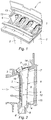
- a distributor 1 comprises a plurality of stationary vanes 2, forming a grid that straighten the flow of air passing through the gas stream of the engine.
- the arrow of the figure 2 represents the flow direction of the gas, from upstream to downstream. This vein is delimited by an outer shell 3 and an inner shell 4, supporting the blades 2.
- Each blade 2 is hollow and comprises a central cavity 5 within which is inserted a cooling jacket 6.
- the leftmost cooling jacket 6 has been shown partially out of the cavity 5 of its receiving blade 2, to help understanding the shape of the various elements. We will describe later a particular set of a dawn 2 and a jacket 6, it being understood that all the sets 2, 6 of the distributor 1 are similar in their structure.
- the cavity 5 of the blade 2 has an external opening 7 and an internal opening 8, respectively in the outer and inner ring 3 4 of the distributor.
- the jacket 6 is inserted through the external opening 7.
- the jacket 6 comprises a hollow body 9 pierced, here on the upstream side, with a plurality of orifices 10 through which is projected, against the inner wall of the blade 2, air fed into the body 9 of the jacket 6 at a supply pipe 11 located near the outer opening 7 of the blade 2.
- the inner wall of the blade 2 comprises, facing these orifices 10, a plurality of disruptive fins 11, for better cooling of the blade 2, in known manner.
- the liner 6 further includes, on its outer surface, a plurality of bosses 12 - also shown schematically on the figure 2 , although the latter is in section - whose function is to allow the positioning of the liner 2 in the cavity 5 of the blade 2.
- the liner 6 comprises, on the external side, a flange 13.
- This flange 13 is here obtained by forming the sheet forming the liner 6. It could also be reported on the latter.
- the flange 13 is arranged to bear on the flange 14 formed by the distributor around the outer opening 7 formed by the cavity 5 of the blade 2.
- the flange 13 is fixed to this rim 14, by soldering or welding, as will be detailed below.
- the liner 6 On its internal side, the liner 6 comprises an end portion 15, in the extension of its body 6, inserted into the internal opening 8 formed by the blade 2, whose wall 8 'slider form to guide this portion of end 15, in known manner. Due to this freedom of movement, the differences in thermal expansion between the blade 2 and the liner 6 can be absorbed.
- the assembly of the blade 2 and the liner 6 further includes, near the collar 13, an interposing element 16.
- the function of the interposing element 16 is to create a pressure drop in the vicinity collar 13, to avoid or at least limit air leakage, in one direction or the other.
- This interposing element 16 is peripheral around the jacket 6. It can be secured to either the jacket 6 or the distributor 1. It is located at close to the flange 13, that is to say that it is in an area in which its effects can be combined with those of the collar 13. In other words, the pressure losses generated by the interposition element 16 must be sufficient to prevent air leakage through the possible gaps between the flange 13 and the flange 14. In this case, the interposing element 16 is located, under the flange 13, at the wall 7 'of the external opening 7, which is extended by the flange 14 where the flange 13 is fixed.
- interposition element 16 is shown integral with the jacket 6, but it goes without saying that the skilled person will transpose without difficulty to an interposing element 16 integral with the wall 7 'of the outer opening 7 formed by the blade 2.
- the interposition element is designated by the same reference 16.
- the interposing element 16 comprises, according to a first embodiment, a peripheral ring 16, or peripheral strip, fixed around the jacket 6, under the collar 13.
- This ring 16, metal is arranged to extend radially on a distance less than that separating the wall of the liner 16 from the wall 7 'of the external opening 7 at this point, preferably flush with the latter.
- radially is meant radially with respect to the overall axis of the liner, that is to say with respect to its longitudinal direction between the flange 13 and the end portion 15. The pressure loss thus created is sufficient to avoid or limit satisfactorily leaks between the flange 13 and the flange 14.
- the interposing element forms a baffle, for the air flows, over the entire periphery of the jacket 6.
- the interposing element 16 comprises, according to a second embodiment, a strip 16 peripheral, having a certain elasticity.
- This lamella 16, metal has a radial dimension which may possibly be greater than the average distance between the wall of the liner 6 of the wall 7 'of the outer opening 7 at this location.
- the sipe 16 bears on the wall portions 7 ' of opening 7 whose shirt 6 is closer and elastically bends outwards during the introduction of the liner 6, thus compensating for the play. It may also be provided that the dimension of the sipe 16 is such that the sipe comes into contact with the wall 7 'of the opening 7 over the entire periphery of the liner 6, thereby forming a seal.
- the interposing element 16 can either perform the function of a baffle, or perform the function of a seal, or both, depending on whether it touches the wall 7 'of external opening 7 (seal function) or not touching it (baffle function). In all cases, it induces a loss of load at its level.
- the sealing element 16 fills on certain portions - where the strip 16 is not in contact with the wall 7 'of the opening 7 - a baffle function and on others portions - where the blade 16 is in contact with the wall 7 'of the opening 7 - a seal function.
- the interposing element 16 comprises, according to a third embodiment, a peripheral spring 16.
- This spring 16, metal comprises a blade, whose edges are fixed to the surface of the jacket 6, the blade having a section U-shaped flared between the two fixed edges.
- a spring member 16 compensates for a possible play at the outer opening 7 and may, depending on the areas of the jacket 6, perform a seal function and / or baffle, depending on whether the spring 16 is in contact or not with the wall 7 'of the opening 7.
- interposing element has been presented according to three preferred embodiments, but it goes without saying that it is possible to envisage other structures, insofar as they extend between the wall of the jacket 6 and that of the opening 7 to create a pressure drop. We could also combine several elements of interposition and create a kind of labyrinth seal.
- Such a mounting method is very fast and inexpensive. Indeed, instead of being soldered over its entire circumference, the collar 13 is simply welded in a plurality of points (usually referred to as "pointing").
- the assembly is viable in operation because the weld points are sufficient to ensure the holding of the liner 6 on the blade 2, while the interposing element 16 seals or at least the limitation of leaks at the It should be noted that the point-welding fastening between the liner 6 and the flange 14 is sufficiently strong because the mechanical stresses at the level of a distributor liner are not too great.
- the method of attachment can freely be adapted according to mechanical constraints on the one hand, time constraints and mounting cost on the other hand.
- This freedom of adaptation is conferred by the presence of an interposing element between the wall of the liner 6 and the wall 7 'of the opening 7, which makes it possible to choose between brazing and spot welding.
- the step of leveling the flange 13 may be implemented by machining, or preferably by ripping by an EDM machine (this type of routing is well known to those skilled in the art under its English acronym EDM, meaning "Electro-Discharge Machine”).
- EDM Electro-Discharge Machine
- the routing to be operated is very quickly implemented, because it suffices to break down the flange 13, which does not have, in general, a very large thickness. It is simple then, once the liner 6 removed from the central cavity 5 of the blade 2, to report a flange on the body 9 of the liner 6, for example by welding, to reform a new liner. The latter can then be inserted again in the central cavity 5 of the blade 2.
Description
L'invention concerne un ensemble d'une aube et d'une chemise de refroidissement de l'aube, dans un distributeur d'une turbomachine.The invention relates to a set of a blade and a cooling jacket of the blade, in a distributor of a turbomachine.
Une turbomachine comporte des étages rotoriques - de compresseur et/ou de turbine - séparés par des distributeurs. Ces derniers comportent une pluralité d'aubes fixes, destinées à orienter les flux de gaz. Les aubes fixes s'étendent, dans la veine de gaz, entre une virole externe et une virole interne. En raison de la température des gaz qui les parcourent, en particulier dans les distributeurs séparant les étages de turbines, les aubes sont soumises à des conditions de fonctionnement très sévères ; il est donc nécessaire de les refroidir, en général par convection forcée ou bien par impact d'air, à l'intérieur des aubes.A turbomachine comprises rotor stages - compressor and / or turbine - separated by distributors. The latter comprise a plurality of vanes, intended to guide the flow of gas. The vanes extend in the gas vein between an outer shell and an inner shell. Due to the temperature of the gases flowing through them, in particular in the distributors separating the turbine stages, the vanes are subjected to very severe operating conditions; it is therefore necessary to cool them, usually by forced convection or by air impact, inside the blades.
Pour un refroidissement par impact d'air, on peut utiliser des chemises longitudinales multiperforées. Ces chemises sont généralement constituées d'un alliage résistant à chaud, par exemple à base de Chrome (Cr), Cobalt (Co) et Nickel (Ni). Une telle chemise est glissée longitudinalement dans la cavité d'une aube. Elle est alimentée en air de refroidissement au niveau de la virole externe. En raison de la différence de pression existant entre la cavité intérieure de la chemise et la cavité ménagée entre la chemise et l'aube, une partie de l'air est projetée, via les perforations de la chemise, contre la paroi interne de l'aube, assurant ainsi son refroidissement. Cet air est ensuite évacué, le long du bord de fuite de l'aube, par des perforations calibrées, dans la veine de gaz. Le reste de l'air est évacué à travers la virole interne vers d'autres parties du moteur à refroidir, telles que le disque de turbine ou les paliers.For air-impact cooling, multi-perforated longitudinal liners can be used. These jackets are generally made of a hot-resistant alloy, for example based on Chromium (Cr), Cobalt (Co) and Nickel (Ni). Such a shirt is slid longitudinally into the cavity of a blade. It is supplied with cooling air at the outer shell. Due to the pressure difference between the inner cavity of the liner and the cavity between the liner and the blade, a portion of the air is projected, via the perforations of the liner, against the inner wall of the liner. dawn, thus ensuring its cooling. This air is then evacuated along the trailing edge of the blade by calibrated perforations in the gas vein. The remainder of the air is discharged through the inner shroud to other parts of the engine to be cooled, such as the turbine disk or bearings.
La cavité de l'aube ménage deux ouvertures dans les plates-formes interne et externe. La chemise est généralement fixée, du côté externe, à la paroi de l'ouverture externe, par brasage ou soudage, par exemple. On obtient ainsi une sorte de liaison glissière brasée. La chemise est en outre guidée, au niveau de son autre portion d'extrémité, dans l'ouverture interne, dont la paroi forme glissière à cet effet et qui permet de compenser les dilatations différentielles entre la chemise et l'aube.The dawn cavity provides two openings in the inner and outer platforms. The liner is generally attached externally to the wall of the outer opening by soldering or welding, for example. This gives a kind of brazed slide connection. The liner is further guided, at its other end portion, in the inner opening, whose wall slid form for this purpose and which makes it possible to compensate for the differential expansions between the liner and the blade.
Selon une configuration avantageuse, la chemise comporte, de son côté externe, une collerette, brasée sur le distributeur. Une chemise à collerette est connue du document
Il est essentiel d'assurer une bonne étanchéité de la chemise sur l'aube, au niveau de la collerette. En effet, si ce n'est pas le cas, des fuites se produisent dans un sens ou dans l'autre et sont préjudiciables dans les deux cas. Ainsi, si la pression du côté externe de la virole externe du distributeur est supérieure à la pression dans la cavité ménagée entre la chemise et l'aube, de l'air va pénétrer dans cette dernière cavité ; il en résulte une augmentation de la pression à l'extérieur de la chemise, l'air ayant moins tendance à être projetée de l'intérieur de la chemise contre l'aube et le refroidissement de cette dernière étant donc moins bien assuré. A l'inverse, si la pression est plus importante dans la cavité entre la chemise et l'aube que du côté externe de la virole externe du distributeur, l'air, qui a servi à refroidir l'aube et s'est donc réchauffé, s'échappe de cette dernière cavité et détériore le refroidissement, assuré par ailleurs, du côté externe du distributeur. On pourrait pallier en partie les problèmes ci-dessus en augmentant le volume du flux de refroidissement à ce niveau ; toutefois, augmenter le volume à un endroit signifie le diminuer à un autre.It is essential to ensure a good tightness of the shirt on the dawn, at the level of the collar. Indeed, if this is not the case, leaks occur in one direction or the other and are detrimental in both cases. Thus, if the pressure on the outer side of the outer shell of the distributor is greater than the pressure in the cavity between the jacket and the blade, air will enter the latter cavity; This results in an increase in the pressure outside the jacket, the air being less likely to be projected from the inside of the shirt against the blade and the cooling of the latter is therefore less well ensured. Conversely, if the pressure is greater in the cavity between the jacket and the blade than on the outer side of the outer ring of the dispenser, the air, which was used to cool the dawn and therefore warmed , escapes from the latter cavity and deteriorates the cooling, provided elsewhere, the outer side of the dispenser. Some of the above problems could be overcome by increasing the volume of the cooling flow at this level; however, increasing the volume in one place means decreasing it to another.
Aucune de ces situations n'est satisfaisante et il est nécessaire d'avoir une liaison d'étanchéité satisfaisante au niveau de la collerette.None of these situations is satisfactory and it is necessary to have a satisfactory sealing connection at the flange.
Une telle liaison peut être obtenue par brasage. Toutefois, quand bien même un tel brasage peut être contrôlé visuellement sur la collerette, il existe un risque de brasage incomplet ou défaillant, laissant place à une éventuelle fuite d'air.Such a connection can be obtained by brazing. However, even if such brazing can be visually controlled on the flange, there is a risk of incomplete or failed brazing, leaving room for a possible air leak.
Les documents
La présente invention vise à proposer un ensemble d'une aube et d'une chemise à collerette de refroidissement de l'aube dans lequel l'étanchéité de la fixation au niveau de la collerette est assurée.The present invention aims to provide an assembly of a blade and a cooling collar jacket of the blade in which the sealing of the fastener at the collar is provided.
C'est ainsi que l'invention concerne un ensemble d'une aube et d'une chemise de refroidissement de l'aube, ici dans un distributeur d'une selon la revendication 1 l'aube comportant une cavité centrale, avec au moins une première ouverture, dans laquelle s'étend la chemise, la chemise comportant une collerette fixée sur le rebord de l'ouverture, caractérisé par le fait qu'il comporte, à
proximité de la collerette, un élément d'interposition périphérique entre la paroi de la chemise et la paroi de l'ouverture.Thus, the invention relates to an assembly of a blade and a cooling jacket of the blade, here in a distributor of one according to claim 1, the blade comprising a central cavity, with at least one first opening, in which the liner extends, the liner having a flange fixed to the rim of the opening, characterized in that it comprises, at
proximity of the flange, a peripheral interposition element between the wall of the jacket and the wall of the opening.
Un tel élément d'interposition crée une perte de charge. Par perte de charge, on entend, non seulement, une perte de charge classique créée par un rétrécissement de la section de passage d'un écoulement ou par une chicane, mais encore, une perte de charge - infinie - créée par un joint étanche.Such an interposition element creates a pressure drop. By loss of load is meant not only a conventional pressure loss created by a narrowing of the passage section of a flow or a baffle, but also an pressure drop - infinite - created by a seal.
Grâce à la combinaison d'une collerette fixée au rebord et d'un élément d'interposition à proximité de cette collerette, l'air ne fuit pas - du moins d'éventuelles fuites ne sont pas significatives - et une éventuelle lacune de brasure n'est pas problématique. En effet, la collerette étant fixée, d'éventuelles fuites d'air ne pourraient se faire que par un jeu faible entre la collerette et le rebord. Or, de telles fuites par un faible interstice ne sont pas possibles en raison de l'élément d'interposition créant une perte de charge, ni dans un sens, ni dans l'autre.Thanks to the combination of a flange fixed to the rim and an interposition element near this collar, the air does not leak - at least any leaks are not significant - and a possible solder gap n is not problematic. Indeed, the flange being fixed, any air leakage could be done only by a small clearance between the flange and the flange. However, such leakage by a small gap is not possible because of the interposing element creating a pressure drop, neither in one direction nor in the other.
En résolvant un problème précis, la demanderesse a par ailleurs découvert qu'il était possible de simplifier de manière considérable le montage de l'ensemble. En effet, la présence d'un élément d'interposition à proximité de la collerette a un effet très efficace sur les fuites d'air, si bien qu'il n'est plus nécessaire de braser parfaitement la collerette sur le distributeur. Il est donc possible de simplement fixer, par un soudage par points entre la collerette et le rebord, la chemise sur l'aube, les fuites étant évitées grâce à l'élément d'interposition. Les gains de temps et de coût sont considérables en comparaison avec un brasage sur toute la périphérie de la collerette.In solving a specific problem, the applicant has also discovered that it was possible to greatly simplify the assembly of the assembly. Indeed, the presence of an interposing element near the collar has a very effective effect on air leakage, so it is no longer necessary to perfectly braze the flange on the distributor. It is therefore possible to simply fix, by spot welding between the flange and the flange, the jacket on the blade, the leaks being avoided thanks to the interposing element. The time and cost savings are considerable in comparison with soldering over the entire periphery of the collar.
L'élément d'interposition peut remplir une fonction de chicane et/ou de joint d'étanchéité.The interposer may serve a baffle and / or seal function.
De préférence, la cavité centrale ménageant une deuxième ouverture, la chemise comporte une portion d'extrémité, opposée à la collerette, qui est guidée dans la deuxième ouverture, dont la paroi forme glissière à cet effet.Preferably, the central cavity providing a second opening, the liner has an end portion, opposite the flange, which is guided in the second opening, the wall forming a slide for this purpose.
Avantageusement dans ce cas, un jeu est ménagé entre la chemise et la paroi de la première ouverture.Advantageously in this case, a clearance is provided between the jacket and the wall of the first opening.
Selon une première forme de réalisation particulière, l'élément d'interposition comporte un jonc périphérique formant une chicane.According to a first particular embodiment, the interposing element comprises a peripheral ring forming a baffle.
Selon une deuxième forme de réalisation particulière, l'élément d'interposition comporte une lamelle élastique.According to a second particular embodiment, the interposing element comprises an elastic lamella.
Selon une troisième forme de réalisation particulière, l'élément d'interposition comporte un ressort périphérique.According to a third particular embodiment, the interposing element comprises a peripheral spring.
L'invention concerne également un distributeur de turbomachine, comportant une pluralité d'ensembles tels que présentés ci-dessus, ainsi qu'une turbomachine comportant un tel distributeur.Un procédé simplifié, que l'on a présenté ci-dessus, de montage d'une chemise de refroidissement dans une aube creuse de distributeur de turbomachine, pour former l'ensemble de l'invention, l'aube comportant une cavité centrale, avec au moins une première ouverture, et la chemise comportant une collerette, dans lequel :
- on insère la chemise dans la cavité de l'aube, par la première ouverture, de manière à placer un élément d'interposition périphérique entre la paroi de la chemise et la paroi de la première ouverture et
- on soude par points la collerette sur le rebord.
- inserting the liner into the blade cavity, through the first opening, so as to place a peripheral interposing element between the liner wall and the wall of the first opening and
- the collar is dotted by points on the rim.
Grâce à l'utilisation de l'élément d'interposition de l'invention, l'utilisation d'une chemise à collerette peut être mise en oeuvre industriellement, en maîtrisant les risques de fuites d'air. Il est ainsi possible, en cas de réparation d'un distributeur et donc de l'ensemble de l'invention, pour démonter et remonter la chemise de l'aube, de mettre en oeuvre un procédé dans lequel :
- on arase la collerette de la chemise, jusqu'au rebord, sans araser l'élément d'interposition,
- on enlève la chemise du corps central de l'aube, par l'ouverture,
- on rapporte une nouvelle collerette sur la chemise,
- on insère la chemise, avec la nouvelle collerette, dans la cavité de l'aube, par la première ouverture, de manière à placer l'élément d'interposition périphérique entre la paroi de la chemise et la paroi de la première ouverture et
- on fixe la collerette sur le rebord.
- the collar of the shirt is cut to the brim, without striking the interposition element,
- we remove the shirt from the central body of the dawn, through the opening,
- there is a new collar on the shirt,
- the jacket, with the new flange, is inserted into the cavity of the blade, through the first opening, so as to place the peripheral interposing element between the wall of the jacket and the wall of the first opening and
- we fix the collar on the rim.
Un tel procédé présente l'avantage de sa simplicité de mise en oeuvre.Such a method has the advantage of its simplicity of implementation.
On note que l'invention s'applique particulièrement bien à un ensemble dont la chemise est ouverte des deux côtés, la portion d'extrémité opposée à la collerette étant guidée dans une ouverture dont la paroi forme glissière, mais il va de soi que l'invention s'applique également à un ensemble dont la chemise n'est ouverte que du côté de la collerette, sans être nécessairement guidée dans une glissière à son autre extrémité.It is noted that the invention is particularly applicable to an assembly whose jacket is open on both sides, the end portion opposite the flange being guided in an opening whose wall form slider, but it goes without saying that the The invention also applies to an assembly whose jacket is open only on the side of the collar, without necessarily being guided in a slide at its other end.
L'invention sera mieux comprise à l'aide de la description suivante des formes de réalisation préférées de l'invention, en référence aux planches annexées, sur lesquelles :
- la
figure 1 représente une vue en perspective schématique d'une portion du distributeur de l'invention ; - la
figure 2 représente une vue en coupe schématique de l'ensemble de l'invention ; - la
figure 3 représente une vue en coupe schématique de l'élément d'interposition selon une première forme de réalisation de l'ensemble de l'invention ; - la
figure 4 représente une vue en coupe schématique de l'élément d'interposition selon une deuxième forme de réalisation de l'ensemble de l'invention et - la
figure 5 représente une vue en coupe schématique de l'élément d'interposition selon une troisième forme de réalisation de l'ensemble de l'invention.
- the
figure 1 is a schematic perspective view of a portion of the dispenser of the invention; - the
figure 2 is a schematic sectional view of the assembly of the invention; - the
figure 3 is a schematic sectional view of the interposing element according to a first embodiment of the whole of the invention; - the
figure 4 is a schematic sectional view of the interposing element according to a second embodiment of the whole of the invention and - the
figure 5 is a schematic sectional view of the interposer according to a third embodiment of the whole of the invention.
En référence aux
Chaque aube 2 est creuse et comporte une cavité centrale 5 au sein de laquelle est insérée une chemise de refroidissement 6. Sur la
La cavité 5 de l'aube 2 ménage une ouverture externe 7 et une ouverture interne 8, respectivement dans les viroles externe 3 et interne 4 du distributeur. Pour être montée dans l'aube 2, la chemise 6 est insérée par l'ouverture externe 7.The cavity 5 of the
La chemise 6 comporte un corps creux 9 percé, ici du côté amont, d'une pluralité d'orifices 10 par lesquels est projeté, contre la paroi interne de l'aube 2, de l'air alimenté dans le corps 9 de la chemise 6 au niveau d'un tuyau d'alimentation 11 situé à proximité de l'ouverture externe 7 de l'aube 2. En l'espèce, la paroi interne de l'aube 2 comporte, face à ces orifices 10, une pluralité d'ailettes 11 formant perturbateurs, pour un meilleur refroidissement de l'aube 2, de manière connue. La chemise 6 comporte par ailleurs, sur sa surface externe, une pluralité de bossages 12 - également représentés schématiquement sur la
La chemise 6 comporte, du côté externe, une collerette 13. Cette collerette 13 est ici obtenue par formage de la tôle formant la chemise 6. Elle pourrait également être rapportée sur cette dernière. La collerette 13 est agencée pour venir en appui sur le rebord 14 formé par le distributeur autour de l'ouverture externe 7 ménagée par la cavité 5 de l'aube 2. La collerette 13 est fixée à ce rebord 14, par brasage ou soudage, comme on le détaillera plus loin.The
De son côté interne, la chemise 6 comporte une portion d'extrémité 15, dans le prolongement de son corps 6, insérée dans l'ouverture interne 8 ménagée par l'aube 2, dont la paroi 8' forme glissière pour guider cette portion d'extrémité 15, de manière connue. Du fait de cette liberté de mouvement, les différences de dilatation thermique entre l'aube 2 et la chemise 6 peuvent être absorbées.On its internal side, the
L'ensemble de l'aube 2 et de la chemise 6 comporte par ailleurs, à proximité de la collerette 13, un élément d'interposition 16. La fonction de l'élément d'interposition 16 est de créer une perte de charge à proximité de la collerette 13, pour éviter ou du moins limiter les fuites d'air, dans un sens ou dans l'autre. Cet élément d'interposition 16 est périphérique autour de la chemise 6. Il peut être solidaire, soit de la chemise 6, soit du distributeur 1. Il se situe à proximité de la collerette 13, c'est-à-dire qu'il se situe dans une zone dans laquelle ses effets peuvent être combinés à ceux de la collerette 13. Autrement dit, les pertes de charge générées par l'élément d'interposition 16 doivent être suffisantes pour éviter les fuites d'air par les éventuels interstices existant entre la collerette 13 et le rebord 14. En l'espèce, l'élément d'interposition 16 est situé, sous la collerette 13, au niveau de la paroi 7' de l'ouverture externe 7, qui se prolonge par le rebord 14 où est fixée la collerette 13.The assembly of the
Trois formes de réalisation particulières de l'élément d'interposition vont maintenant être décrites, en relation avec les
En référence à la
En référence à la
Grâce à cette forme de réalisation, il est possible de ménager un jeu entre la chemise 6 et la paroi 7' de l'ouverture externe 7. Un tel jeu autorise un montage plus simple de la chemise 6. Lors de son introduction dans l'aube 2, la chemise 6 est guidée, au niveau de sa portion d'extrémité 15, dans la glissière 8 située du côté interne de l'aube 2. Ce guidage se fait librement car il n'est pas gêné par un défaut d'alignement de l'ouverture interne 8 et de l'ouverture externe 7, du fait de la présence d'un jeu au niveau de cette dernière. Un tel jeu n'est pas préjudiciable au montage car il est compensé par l'élasticité de la lamelle 16. Ainsi, la lamelle 16 peut passer dans l'ouverture 7 et remplir sa fonction de limitation des fuites. Grâce à la lamelle 16, la présence d'un jeu n'implique pas de fuites ; le jeu et les avantages qu'il implique sont donc autorisés par la présence de la lamelle 16.With this embodiment, it is possible to provide a clearance between the
Dans cette forme de réalisation, l'élément d'interposition 16 peut, soit remplir la fonction d'une chicane, soit remplir la fonction d'un joint d'étanchéité, soit les deux, selon qu'il touche la paroi 7' de l'ouverture externe 7 (fonction de joint) ou qu'il ne la touche pas (fonction de chicane). Dans tous les cas, il induit une perte de charge à son niveau. Lorsqu'il remplit les deux fonctions, l'élément d'étanchéité 16 remplit sur certaines portions - où la lamelle 16 n'est pas en contact avec la paroi 7' de l'ouverture 7 - une fonction de chicane et sur d'autres portions - où la lamelle 16 est en contact avec la paroi 7' de l'ouverture 7 - une fonction de joint d'étanchéité.In this embodiment, the interposing
En référence à la
L'élément d'interposition a été présenté selon trois formes de réalisations préférées, mais il va de soi qu'il est possible d'envisager d'autres structures, dans la mesure où elles s'étendent entre la paroi de la chemise 6 et celle de l'ouverture 7 pour créer une perte de charge. On pourrait d'ailleurs combiner plusieurs éléments d'interposition et créer une sorte de joint labyrinthe.The interposing element has been presented according to three preferred embodiments, but it goes without saying that it is possible to envisage other structures, insofar as they extend between the wall of the
Grâce à l'élément d'interposition 16, les fuites d'air au niveau de la collerette 13 sont, si ce n'est complètement évitées, du moins largement limitées. La collerette 13 peut être fixée au rebord 14 par brasage. Dans un tel cas, une éventuelle lacune de matériau de brasure n'est pas rédhibitoire car l'élément d'interposition interdit ou limite les fuites. L'utilisation d'un élément d'interposition permet également la mise en oeuvre d'un procédé de montage particulier de la chemise 6 dans l'aube 2, dans lequel :
- on insère la chemise 6 dans la cavité 5 de l'aube 2,
par l'ouverture externe 7 et - on soude par points
la collerette 13 sur le rebord 14.
- the
jacket 6 is inserted into the cavity 5 of theblade 2, through theexternal opening 7 and - the
flange 13 is welded in points on theflange 14.
Un tel procédé de montage est très rapide et peu onéreux. En effet, au lieu d'être brasée sur toute sa circonférence, la collerette 13 est simplement soudée en une pluralité de points (on parle généralement de "pointage"). L'ensemble est viable en fonctionnement car les points de soudure sont suffisants pour assurer la tenue de la chemise 6 sur l'aube 2, tandis que l'élément d'interposition 16 assure l'étanchéité ou du moins la limitation des fuites au niveau de la collerette 13. On note que la fixation par soudage par points entre la chemise 6 et le rebord 14 est suffisamment résistante car les contraintes mécaniques au niveau d'une chemise de distributeur ne sont pas trop importantes.Such a mounting method is very fast and inexpensive. Indeed, instead of being soldered over its entire circumference, the
Ainsi, le mode de fixation peut librement être adapté en fonction des contraintes mécaniques d'une part, des contraintes de temps et de coût de montage d'autre part. Cette liberté d'adaptation est conférée par la présence d'un élément d'interposition entre la paroi de la chemise 6 et la paroi 7' de l'ouverture 7, qui permet de choisir entre un brasage et un soudage par points.Thus, the method of attachment can freely be adapted according to mechanical constraints on the one hand, time constraints and mounting cost on the other hand. This freedom of adaptation is conferred by the presence of an interposing element between the wall of the
En cas de réparation du distributeur 1, il est possible, pour chaque ensemble d'une aube 2 et d'une chemise 6, de mettre en oeuvre un procédé de réparation dans lequel :
- on arase la collerette 13 de la chemise 6,
jusqu'au rebord 14, sans araser l'élément d'interposition 16, - on enlève la chemise 6 du corps central 5 de l'aube 2,
par l'ouverture 7, - on rapporte une nouvelle collerette sur la
chemise 6, - on insère la chemise 6, avec la nouvelle collerette, dans la cavité 5 de l'aube 2,
par l'ouverture externe 7, de manière àplacer l'élément d'interposition 16 périphérique entre la paroi de la chemise 6 et la paroi 7' de l'ouverture 7 et - on fixe la collerette 13 sur le rebord 14.
- the
flange 13 of thejacket 6 is flared to theflange 14, without striking theinterposition element 16, - the
liner 6 of the central body 5 of theblade 2 is removed through theopening 7, - we report a new collar on the
shirt 6, - the
liner 6, with the new flange, is inserted into the cavity 5 of theblade 2, through theexternal opening 7, so as to place theperipheral element 16 between the wall of theliner 6 and the wall 7 'ofopening 7 and - the
flange 13 is fixed on theflange 14.
L'étape d'arasement de la collerette 13 peut être mise en oeuvre par usinage, ou de préférence par défonçage par une machine à électro-érosion (ce type de défonçage est bien connu de l'homme du métier sous son acronyme anglais de défonçage EDM, signifiant "Electro-Discharge Machine"). Le défonçage à opérer est très rapidement mis en oeuvre, car il suffit de défoncer la collerette 13, qui ne présente pas, en général, une très grande épaisseur. Il est simple ensuite, une fois la chemise 6 enlevée de la cavité centrale 5 de l'aube 2, de rapporter une collerette sur le corps 9 de la chemise 6, par exemple par soudage, pour reformer une nouvelle chemise. Cette dernière peut alors être de nouveau insérée dans la cavité centrale 5 de l'aube 2.The step of leveling the
Claims (9)
- Turbine engine nozzle (1) comprising a plurality of assemblies of a vane (2) and a cooling jacket (6) for the vane (2), in each assembly the vane (2) being supported by an outer shroud (3) and an inner shroud (4), the vane (2) comprising a central cavity (5) providing, in the outer shroud (3), an outer opening (7) in which the jacket (6) runs, the jacket (6) being of longitudinal axis and comprising a flange (13) fastened to a shoulder (14) formed by the nozzle (1) around the outer opening (7), the shoulder (14) comprising a longitudinal wall (7'), the nozzle (1) being characterised in that it comprises in each assembly, close to and away from the flange (13), an interposition element (16) running along the entire periphery of the jacket (6) between the wall of the jacket (6) and the longitudinal wall (7') of the shoulder (14).
- Nozzle (1), according to claim 1, in which the interposition element (16) is a baffle or seal.
- Nozzle (1), according to either of claims 1 or 2, in which, the central cavity (5) providing an inner opening (8), the jacket (6) comprises an end portion (15), opposite the flange (13), which is guided in the inner opening (8), the wall (8') of which forms a slide for this purpose.
- Nozzle (1), according to claim 3, in which a clearance is provided between the jacket (6) and the longitudinal wall (7') of the shoulder (14).
- Nozzle (1), according to any one of claims 1 to 4, in which the interposition element comprises a peripheral ring (16) forming a baffle.
- Nozzle (1), according to any one of claims 1 to 4, in which the interposition element comprises an elastic strip (16).
- Nozzle (1), according to any one of claims 1 to 4, in which the interposition element comprises a peripheral spring (16).
- Nozzle (1), according to any one of claims 1 to 7, in which the flange (13) is fastened to the shoulder (14) by spot welding.
- Turbine engine comprising a nozzle (1) according to any one of claims 1 to 8.
Applications Claiming Priority (1)
| Application Number | Priority Date | Filing Date | Title |
|---|---|---|---|
| FR0602716A FR2899271B1 (en) | 2006-03-29 | 2006-03-29 | DUSTBOARD AND COOLING SHIELD ASSEMBLY, TURBOMACHINE DISPENSER COMPRISING THE ASSEMBLY, TURBOMACHINE, METHOD OF ASSEMBLING AND REPAIRING THE ASSEMBLY |
Publications (2)
| Publication Number | Publication Date |
|---|---|
| EP1840331A1 EP1840331A1 (en) | 2007-10-03 |
| EP1840331B1 true EP1840331B1 (en) | 2017-05-31 |
Family
ID=37429322
Family Applications (1)
| Application Number | Title | Priority Date | Filing Date |
|---|---|---|---|
| EP07290365.1A Active EP1840331B1 (en) | 2006-03-29 | 2007-03-26 | Turbomachine nozzle |
Country Status (7)
| Country | Link |
|---|---|
| US (1) | US7819628B2 (en) |
| EP (1) | EP1840331B1 (en) |
| JP (1) | JP2007263115A (en) |
| CN (1) | CN101122243B (en) |
| CA (1) | CA2582638C (en) |
| FR (1) | FR2899271B1 (en) |
| RU (1) | RU2439334C2 (en) |
Families Citing this family (34)
| Publication number | Priority date | Publication date | Assignee | Title |
|---|---|---|---|---|
| FR2919897B1 (en) * | 2007-08-08 | 2014-08-22 | Snecma | TURBINE DISPENSER SECTOR |
| FR2955145B1 (en) * | 2010-01-14 | 2012-02-03 | Snecma | HIGH PRESSURE TURBINE DISPENSER OF A TURBOREACTOR |
| FR2970666B1 (en) | 2011-01-24 | 2013-01-18 | Snecma | PROCESS FOR PERFORATING AT LEAST ONE WALL OF A COMBUSTION CHAMBER |
| FR2976616B1 (en) * | 2011-06-17 | 2015-01-09 | Snecma | VENTILATION SYSTEM FOR A HOLLOW BLADE OF A TURBINE DISPENSER IN A TURBOMACHINE |
| EP2540969A1 (en) * | 2011-06-27 | 2013-01-02 | Siemens Aktiengesellschaft | Impingement cooling of turbine blades or vanes |
| US8864445B2 (en) * | 2012-01-09 | 2014-10-21 | General Electric Company | Turbine nozzle assembly methods |
| US9011079B2 (en) * | 2012-01-09 | 2015-04-21 | General Electric Company | Turbine nozzle compartmentalized cooling system |
| US20130223987A1 (en) * | 2012-02-29 | 2013-08-29 | Scott Stafford | Turbine Nozzle Insert |
| US10822976B2 (en) * | 2013-06-03 | 2020-11-03 | General Electric Company | Nozzle insert rib cap |
| US20140356155A1 (en) * | 2013-06-03 | 2014-12-04 | General Electric Company | Nozzle Insert Rib Cap |
| WO2015009392A2 (en) * | 2013-07-19 | 2015-01-22 | General Electric Comapny | Turbine nozzle with impingement baffle |
| WO2015169555A1 (en) * | 2014-05-08 | 2015-11-12 | Siemens Aktiengesellschaft | Turbine assembly and corresponding method of operation |
| EP2949872A1 (en) * | 2014-05-27 | 2015-12-02 | Siemens Aktiengesellschaft | Turbomachine with a seal for separating working fluid and coolant fluid of the turbomachine and use of the turbomachine |
| EP3149311A2 (en) | 2014-05-29 | 2017-04-05 | General Electric Company | Turbine engine and particle separators therefore |
| US11033845B2 (en) * | 2014-05-29 | 2021-06-15 | General Electric Company | Turbine engine and particle separators therefore |
| RU2581010C1 (en) * | 2014-11-18 | 2016-04-10 | Акционерное общество "Научно-производственный центр газотурбостроения "Салют" (АО "НПЦ газотурбостроения "Салют") | Method of repair of control gear of guide vanes of turbine compressor of bypass gas turbine engine |
| US10450880B2 (en) * | 2016-08-04 | 2019-10-22 | United Technologies Corporation | Air metering baffle assembly |
| DE102016216858A1 (en) * | 2016-09-06 | 2018-03-08 | Rolls-Royce Deutschland Ltd & Co Kg | Blade for a turbomachine and method for assembling a blade for a turbomachine |
| US10677091B2 (en) * | 2016-11-17 | 2020-06-09 | Raytheon Technologies Corporation | Airfoil with sealed baffle |
| US10577943B2 (en) | 2017-05-11 | 2020-03-03 | General Electric Company | Turbine engine airfoil insert |
| DE102017208678A1 (en) | 2017-05-23 | 2018-11-29 | Siemens Aktiengesellschaft | Turbine blade with sheet metal insert |
| US10815806B2 (en) * | 2017-06-05 | 2020-10-27 | General Electric Company | Engine component with insert |
| EP3421722A1 (en) * | 2017-06-29 | 2019-01-02 | Siemens Aktiengesellschaft | Turbine assembly for impingement cooling and method of assembling |
| FR3074521B1 (en) | 2017-12-06 | 2019-11-22 | Safran Aircraft Engines | TURBINE DISPENSER SECTOR FOR AN AIRCRAFT TURBOMACHINE |
| FR3076852B1 (en) * | 2018-01-16 | 2020-01-31 | Safran Aircraft Engines | TURBOMACHINE RING |
| FR3094034B1 (en) | 2019-03-20 | 2021-03-19 | Safran Aircraft Engines | VENTILATION TUBULAR SHIRT FOR A TURBOMACHINE DISTRIBUTOR |
| PL431184A1 (en) * | 2019-09-17 | 2021-03-22 | General Electric Company Polska Spółka Z Ograniczoną Odpowiedzialnością | Turboshaft engine set |
| US11156105B2 (en) * | 2019-11-08 | 2021-10-26 | Raytheon Technologies Corporation | Vane with seal |
| US11174794B2 (en) * | 2019-11-08 | 2021-11-16 | Raytheon Technologies Corporation | Vane with seal and retainer plate |
| US11261748B2 (en) * | 2019-11-08 | 2022-03-01 | Raytheon Technologies Corporation | Vane with seal |
| CN112228905B (en) * | 2020-10-13 | 2022-01-21 | 西北工业大学 | Channel structure capable of restraining flow distribution deviation of supercritical fluid |
| FR3126020B1 (en) * | 2021-08-05 | 2023-08-04 | Safran Aircraft Engines | Distributor Hollow Blade Cooling Jacket |
| FR3129429A1 (en) | 2021-11-24 | 2023-05-26 | Safran Aircraft Engines | TURBINE DISTRIBUTOR SECTOR FOR AN AIRCRAFT TURBOMACHINE |
| FR3130314A1 (en) | 2021-12-14 | 2023-06-16 | Safran Aircraft Engines | TURBINE DISTRIBUTOR SECTOR FOR AN AIRCRAFT TURBOMACHINE |
Citations (1)
| Publication number | Priority date | Publication date | Assignee | Title |
|---|---|---|---|---|
| US6561757B2 (en) * | 2001-08-03 | 2003-05-13 | General Electric Company | Turbine vane segment and impingement insert configuration for fail-safe impingement insert retention |
Family Cites Families (15)
| Publication number | Priority date | Publication date | Assignee | Title |
|---|---|---|---|---|
| US3301527A (en) * | 1965-05-03 | 1967-01-31 | Gen Electric | Turbine diaphragm structure |
| FR2094033A1 (en) * | 1970-06-04 | 1972-02-04 | Westinghouse Electric Corp | |
| US3846041A (en) * | 1972-10-31 | 1974-11-05 | Avco Corp | Impingement cooled turbine blades and method of making same |
| CA1125660A (en) * | 1979-06-29 | 1982-06-15 | David L. Brown | Cooled vane structure for a combustion turbine engine |
| US4381173A (en) * | 1980-08-25 | 1983-04-26 | United Technologies Corporation | Coolable rotor blade assembly for an axial flow rotary machine |
| US5145315A (en) * | 1991-09-27 | 1992-09-08 | Westinghouse Electric Corp. | Gas turbine vane cooling air insert |
| JPH06129204A (en) * | 1992-10-19 | 1994-05-10 | Mitsubishi Heavy Ind Ltd | Gas turbine cooling structure for gas turbine stator vane |
| JP3324256B2 (en) * | 1994-02-01 | 2002-09-17 | 石川島播磨重工業株式会社 | Turbine vane assembly method |
| JP3480069B2 (en) * | 1994-10-11 | 2003-12-15 | 石川島播磨重工業株式会社 | Fixed cooling wing of jet engine |
| US5630700A (en) * | 1996-04-26 | 1997-05-20 | General Electric Company | Floating vane turbine nozzle |
| US6453557B1 (en) * | 2000-04-11 | 2002-09-24 | General Electric Company | Method of joining a vane cavity insert to a nozzle segment of a gas turbine |
| EP1191189A1 (en) * | 2000-09-26 | 2002-03-27 | Siemens Aktiengesellschaft | Gas turbine blades |
| FR2856729B1 (en) * | 2003-06-30 | 2005-09-23 | Snecma Moteurs | COOLING AUBES OF GAS TURBINE ENGINE. |
| US7008178B2 (en) * | 2003-12-17 | 2006-03-07 | General Electric Company | Inboard cooled nozzle doublet |
| US7104756B2 (en) * | 2004-08-11 | 2006-09-12 | United Technologies Corporation | Temperature tolerant vane assembly |
-
2006
- 2006-03-29 FR FR0602716A patent/FR2899271B1/en active Active
-
2007
- 2007-03-26 EP EP07290365.1A patent/EP1840331B1/en active Active
- 2007-03-28 US US11/692,677 patent/US7819628B2/en active Active
- 2007-03-28 CA CA2582638A patent/CA2582638C/en active Active
- 2007-03-28 JP JP2007084044A patent/JP2007263115A/en active Pending
- 2007-03-28 RU RU2007111392/06A patent/RU2439334C2/en active
- 2007-03-29 CN CN2007100917400A patent/CN101122243B/en active Active
Patent Citations (1)
| Publication number | Priority date | Publication date | Assignee | Title |
|---|---|---|---|---|
| US6561757B2 (en) * | 2001-08-03 | 2003-05-13 | General Electric Company | Turbine vane segment and impingement insert configuration for fail-safe impingement insert retention |
Also Published As
| Publication number | Publication date |
|---|---|
| RU2439334C2 (en) | 2012-01-10 |
| CA2582638C (en) | 2015-04-28 |
| US20070231150A1 (en) | 2007-10-04 |
| EP1840331A1 (en) | 2007-10-03 |
| JP2007263115A (en) | 2007-10-11 |
| CN101122243B (en) | 2011-04-20 |
| US7819628B2 (en) | 2010-10-26 |
| FR2899271B1 (en) | 2008-05-30 |
| CN101122243A (en) | 2008-02-13 |
| CA2582638A1 (en) | 2007-09-29 |
| FR2899271A1 (en) | 2007-10-05 |
| RU2007111392A (en) | 2008-10-10 |
Similar Documents
| Publication | Publication Date | Title |
|---|---|---|
| EP1840331B1 (en) | Turbomachine nozzle | |
| EP2252773B1 (en) | Stator of a turbomachine | |
| CA2834213C (en) | Sealing device for a turbomachine turbine nozzle | |
| CA2641963C (en) | Blade tip clearance control for a turbine engine high-pressure turbine | |
| EP1783326B1 (en) | Cooling arrangement for a gas turbine blade, gas turbine blade, turbine and gas turbine engine equipped with the same | |
| JP2010038161A (en) | Split doublet power nozzle and related method | |
| CA2638812C (en) | Turbine distributor part | |
| EP2895692B1 (en) | Cooled vane of a high-pressure turbine | |
| CA2472324C (en) | Cooled blade of a gas turbine starter | |
| CA2925438A1 (en) | Rotary assembly for a turbomachine | |
| JP2008196488A (en) | Bling nozzle/carrier joint portion design for steam turbine | |
| CA2641438C (en) | Cooled turbomachine blade | |
| JP4248868B2 (en) | Auxiliary seal for string hinge seal in gas turbine and its mounting method | |
| FR3070715A1 (en) | SEALING TAP INTER SEGMENTS OF AIRCRAFT TURBOMACHINE | |
| CA2478954C (en) | Cooled blade for gas turbine engine | |
| US6773229B1 (en) | Turbine nozzle having angel wing seal lands and associated welding method | |
| JP2000034902A (en) | Cooling rotor blade for gas turbine | |
| US11346246B2 (en) | Brazed in heat transfer feature for cooled turbine components | |
| EP4111036B1 (en) | Nozzle vane for turbomachine, corresponding high or low pressure nozzle for turbomachine, turbomachine and method of manufacturing a vane of a nozzle for turbomachine | |
| EP3853445B1 (en) | Turbine seal | |
| FR3101107A1 (en) | DAWN FOR AN AIRCRAFT TURBOMACHINE | |
| FR3137716A1 (en) | TURBINE DISTRIBUTOR FOR AN AIRCRAFT TURBOMACHINE | |
| WO2023062327A1 (en) | Turbine nozzle guide vane comprising an annular sealing element | |
| FR3094035A1 (en) | TURBOMACHINE VANE EQUIPPED WITH A COOLING CIRCUIT WITH OPTIMIZED CONNECTION ZONE | |
| FR3100572A1 (en) | TURBINE RING SECTOR |
Legal Events
| Date | Code | Title | Description |
|---|---|---|---|
| PUAI | Public reference made under article 153(3) epc to a published international application that has entered the european phase |
Free format text: ORIGINAL CODE: 0009012 |
|
| 17P | Request for examination filed |
Effective date: 20070405 |
|
| AK | Designated contracting states |
Kind code of ref document: A1 Designated state(s): AT BE BG CH CY CZ DE DK EE ES FI FR GB GR HU IE IS IT LI LT LU LV MC MT NL PL PT RO SE SI SK TR |
|
| AX | Request for extension of the european patent |
Extension state: AL BA HR MK YU |
|
| AKX | Designation fees paid |
Designated state(s): DE FR GB |
|
| RAP1 | Party data changed (applicant data changed or rights of an application transferred) |
Owner name: SNECMA |
|
| RAP1 | Party data changed (applicant data changed or rights of an application transferred) |
Owner name: SAFRAN AIRCRAFT ENGINES |
|
| 17Q | First examination report despatched |
Effective date: 20161128 |
|
| REG | Reference to a national code |
Ref country code: DE Ref legal event code: R079 Ref document number: 602007051148 Country of ref document: DE Free format text: PREVIOUS MAIN CLASS: F01D0005180000 Ipc: F01D0009040000 |
|
| GRAP | Despatch of communication of intention to grant a patent |
Free format text: ORIGINAL CODE: EPIDOSNIGR1 |
|
| RIC1 | Information provided on ipc code assigned before grant |
Ipc: F01D 5/18 20060101ALI20170309BHEP Ipc: F01D 9/06 20060101ALI20170309BHEP Ipc: F01D 9/04 20060101AFI20170309BHEP Ipc: F01D 25/12 20060101ALI20170309BHEP Ipc: F01D 11/00 20060101ALI20170309BHEP |
|
| INTG | Intention to grant announced |
Effective date: 20170322 |
|
| GRAS | Grant fee paid |
Free format text: ORIGINAL CODE: EPIDOSNIGR3 |
|
| GRAA | (expected) grant |
Free format text: ORIGINAL CODE: 0009210 |
|
| AK | Designated contracting states |
Kind code of ref document: B1 Designated state(s): DE FR GB |
|
| REG | Reference to a national code |
Ref country code: GB Ref legal event code: FG4D Free format text: NOT ENGLISH |
|
| REG | Reference to a national code |
Ref country code: DE Ref legal event code: R096 Ref document number: 602007051148 Country of ref document: DE |
|
| REG | Reference to a national code |
Ref country code: FR Ref legal event code: PLFP Year of fee payment: 12 |
|
| REG | Reference to a national code |
Ref country code: DE Ref legal event code: R097 Ref document number: 602007051148 Country of ref document: DE |
|
| PLBE | No opposition filed within time limit |
Free format text: ORIGINAL CODE: 0009261 |
|
| STAA | Information on the status of an ep patent application or granted ep patent |
Free format text: STATUS: NO OPPOSITION FILED WITHIN TIME LIMIT |
|
| 26N | No opposition filed |
Effective date: 20180301 |
|
| PGFP | Annual fee paid to national office [announced via postgrant information from national office to epo] |
Ref country code: FR Payment date: 20230222 Year of fee payment: 17 |
|
| PGFP | Annual fee paid to national office [announced via postgrant information from national office to epo] |
Ref country code: GB Payment date: 20230222 Year of fee payment: 17 Ref country code: DE Payment date: 20230221 Year of fee payment: 17 |