EP1840287A2 - Sound-absorbing panel of porous material and production method of the same - Google Patents
Sound-absorbing panel of porous material and production method of the same Download PDFInfo
- Publication number
- EP1840287A2 EP1840287A2 EP07006601A EP07006601A EP1840287A2 EP 1840287 A2 EP1840287 A2 EP 1840287A2 EP 07006601 A EP07006601 A EP 07006601A EP 07006601 A EP07006601 A EP 07006601A EP 1840287 A2 EP1840287 A2 EP 1840287A2
- Authority
- EP
- European Patent Office
- Prior art keywords
- sound
- absorbing
- porous
- veneer
- panel
- Prior art date
- Legal status (The legal status is an assumption and is not a legal conclusion. Google has not performed a legal analysis and makes no representation as to the accuracy of the status listed.)
- Granted
Links
Images





Classifications
-
- E—FIXED CONSTRUCTIONS
- E04—BUILDING
- E04B—GENERAL BUILDING CONSTRUCTIONS; WALLS, e.g. PARTITIONS; ROOFS; FLOORS; CEILINGS; INSULATION OR OTHER PROTECTION OF BUILDINGS
- E04B1/00—Constructions in general; Structures which are not restricted either to walls, e.g. partitions, or floors or ceilings or roofs
- E04B1/62—Insulation or other protection; Elements or use of specified material therefor
- E04B1/74—Heat, sound or noise insulation, absorption, or reflection; Other building methods affording favourable thermal or acoustical conditions, e.g. accumulating of heat within walls
- E04B1/82—Heat, sound or noise insulation, absorption, or reflection; Other building methods affording favourable thermal or acoustical conditions, e.g. accumulating of heat within walls specifically with respect to sound only
- E04B1/84—Sound-absorbing elements
- E04B1/86—Sound-absorbing elements slab-shaped
-
- G—PHYSICS
- G10—MUSICAL INSTRUMENTS; ACOUSTICS
- G10K—SOUND-PRODUCING DEVICES; METHODS OR DEVICES FOR PROTECTING AGAINST, OR FOR DAMPING, NOISE OR OTHER ACOUSTIC WAVES IN GENERAL; ACOUSTICS NOT OTHERWISE PROVIDED FOR
- G10K11/00—Methods or devices for transmitting, conducting or directing sound in general; Methods or devices for protecting against, or for damping, noise or other acoustic waves in general
- G10K11/16—Methods or devices for protecting against, or for damping, noise or other acoustic waves in general
- G10K11/162—Selection of materials
-
- E—FIXED CONSTRUCTIONS
- E04—BUILDING
- E04B—GENERAL BUILDING CONSTRUCTIONS; WALLS, e.g. PARTITIONS; ROOFS; FLOORS; CEILINGS; INSULATION OR OTHER PROTECTION OF BUILDINGS
- E04B1/00—Constructions in general; Structures which are not restricted either to walls, e.g. partitions, or floors or ceilings or roofs
- E04B1/62—Insulation or other protection; Elements or use of specified material therefor
- E04B1/74—Heat, sound or noise insulation, absorption, or reflection; Other building methods affording favourable thermal or acoustical conditions, e.g. accumulating of heat within walls
- E04B1/82—Heat, sound or noise insulation, absorption, or reflection; Other building methods affording favourable thermal or acoustical conditions, e.g. accumulating of heat within walls specifically with respect to sound only
- E04B1/84—Sound-absorbing elements
- E04B2001/8457—Solid slabs or blocks
- E04B2001/8461—Solid slabs or blocks layered
-
- E—FIXED CONSTRUCTIONS
- E04—BUILDING
- E04B—GENERAL BUILDING CONSTRUCTIONS; WALLS, e.g. PARTITIONS; ROOFS; FLOORS; CEILINGS; INSULATION OR OTHER PROTECTION OF BUILDINGS
- E04B1/00—Constructions in general; Structures which are not restricted either to walls, e.g. partitions, or floors or ceilings or roofs
- E04B1/62—Insulation or other protection; Elements or use of specified material therefor
- E04B1/74—Heat, sound or noise insulation, absorption, or reflection; Other building methods affording favourable thermal or acoustical conditions, e.g. accumulating of heat within walls
- E04B1/82—Heat, sound or noise insulation, absorption, or reflection; Other building methods affording favourable thermal or acoustical conditions, e.g. accumulating of heat within walls specifically with respect to sound only
- E04B1/84—Sound-absorbing elements
- E04B2001/8457—Solid slabs or blocks
- E04B2001/8476—Solid slabs or blocks with acoustical cavities, with or without acoustical filling
Definitions
- the present invention relates to a sound-absorbing panel and a production method of the same.
- a sound-absorbing panel constituted from a porous plate, a sound-absorbing panel which has a constitution of combination of both the porous plate and a porous sound-absorbing material are generally known.
- Japanese Patent Application No. H06-348281 discloses a sound absorbing panel which is constituted by providing multiple open aperture portions on a plate member; and by pressing, adhering and integrating the open aperture portions with a metallic porous sound-absorbing material of the same shape as these open aperture portions.
- Japanese Patent No. 3024525 discloses a metallic plate on which pierced apertures are evenly and uniformly provided, and which reduces the sound reflection rate.
- Japanese Patent No. 2993370 discloses a sound-absorbing veneer plate which is constituted by adhering a sound-absorbing base material and a veneer material, and which is constituted by forming multiple small apertures of 0.05-0.5 mm opening diameter on the veneer plate.
- the size of the open aperture is approximately as large as can be recognized by the naked eye; therefore, the metallic porous sound-absorbing material filled in this open aperture is in a state which can be recognized by the naked eye. Therefore, there is a problem in which the appearance of this sound-absorbing plate is determined in accordance with the size of the open aperture and the appearance of the metallic porous sound-absorbing material, and there is a small freedom of design.
- a radius of the pierced aperture is set to be 8-28mm, gaps or intervals between the pierced apertures are set to be 20-100mm which are comparatively large; and therefore, the pierced apertures are set to be a size which can be recognized by the naked eye. Therefore, there is a problem in which the appearance of the metallic plate is mainly determined in accordance with the radius and intervals of the pierced apertures, and there is a small freedom of design.
- the sound-absorbing veneer disclosed in Japanese Patent No. 2993370 has limitations to the material of the veneer because a pulse laser processing machine is used upon forming fine or small apertures on the veneer; therefore, there is a problem in which the freedom of designing is small.
- the sound-absorbing plate which is obtained by combining the porous plate and the porous sound-absorbing material as described in Japanese Patent Application, First Publication No. H06-348281 or Japanese Patent No. 2993370
- fiber sound-absorbing material such as glass wool, rock wool, and the like
- a granular sound-absorbing material that is obtained by solidifying and forming granular mineral material such as pearlite, silver sand, and the like is used.
- the percentage of void space is applied as an indicator or an index upon choosing the constitutional material of the sound-absorbing plate among them.
- the sound-absorbing coefficient is different in accordance with the thickness or length of the fiber even though the percentage of void space is the same, and even in a case in which the same granular sound-absorbing material is used, there is possibility that the sound-absorbing coefficient is different in accordance with a size of inorganic powders or inorganic particles or in accordance with adhering or sticking state of a bonding agent even though the percentage of void space is the same.
- the percentage of void space is the same, there is a difference in pass or channel in which air flows in accordance with the constitutional members; therefore, a relationship between the percentage of void space and the sound-absorbing coefficient is not uniform or constant.
- the present invention was devised with respect to the above-described backgrounds, and has an object to provide a sound-absorbing panel and a production method of the same which have excellent freedom of design and have small differences in the maximum sound-absorbing coefficients among the products.
- Inventors of the present invention have eagerly studied the relationship between the physical properties of the sound-absorbing panel and the maximum sound-absorbing coefficient, a close relationship was found between the value of the airflow resistance and the maximum sound-absorbing coefficient when the porous veneer and the porous sound-absorbing base material are combined, and a phenomena was found in which an excellent maximum sound-absorbing coefficient is obtained when the value of the airflow resistance is in a specific range.
- a sound-absorbing panel includes a panel main body, wherein the panel main body includes both a porous veneer of 0.02-0.5 mm thickness which includes pierced apertures of 0.2 mm or smaller aperture diameters or 0.1 mm or smaller aperture diameters, and a porous sound-absorbing base material arranged at a backside of the porous veneer.
- the panel main body is constituted by arranging the porous veneer and the porous sound-absorbing base material so as to be overlapped.
- the value of the airflow resistance of the panel main body is in the range of 0.1-1.0 Pa.
- the value of the airflow resistance of the porous sound-absorbing base material be in a range of 0.1-0.8 Pa.
- a sound-absorbing panel includes a panel main body, wherein the panel main body includes both a porous veneer of 0.02-0.5 mm thickness which includes pierced apertures of 0.2 mm or smaller aperture diameters or 0.1 mm or smaller aperture diameters, and a supporting base material arranged at the backside of the porous veneer.
- the panel main body is constituted by arranging the porous veneer and the supporting base material so as to be overlapped.
- the value of the airflow resistance of the panel main body is in the range of 0.1-1.0 Pa.
- the supporting base material of the above-described sound-absorbing panel be a honeycomb structure material, a punching metal or an expanded metal.
- both the porous veneer and the porous sound-absorbing base material or the supporting base material be detachably attached.
- a backside air layer be provided at the backside of the porous sound-absorbing base material or the supporting base material.
- a production method of a sound-absorbing panel includes the steps of: forming a porous veneer by forming a plurality of pierced apertures of 0.2 mm or smaller aperture diameters or 0.1 mm or smaller aperture diameters on a veneer of 0.02-0.5 mm thickness; and constituting a panel main body by arranging a porous sound-absorbing base material or a supporting base material at the backside of the porous veneer to be overlapped, along with setting a value of the airflow resistance of the panel main body in the range of 0.1-1.0 Pa.
- a design be applied to a surface of the porous veneer opposite to the backside.
- the value of resistance of air flow of the panel main body is in the range of 0.1-1.0 Pa. Therefore, it is possible to indicate a 60% or larger maximum sound-absorbing coefficient.
- the value of the airflow resistance which has a comparatively strong relationship with the maximum sound-absorbing coefficient is used instead of the percentage of void space. Therefore, there is no possibility in which there are differences of the maximum sound-absorbing coefficients of the sound-absorbing panels among products, and it is possible to constitute the sound-absorbing panel with stable sound-absorbing characteristics.
- the aperture diameter of the pierced aperture is comparatively small. Therefore, the pierced aperture is not conspicuous or an eyesore, and it is possible to freely design the appearance of the sound-absorbing panel without being affected by the pierced aperture.
- the value of the airflow resistance of the porous sound-absorbing base material is in the range of 0.1-0.8 Pa. Therefore, when the panel main body is constituted, there is no possibility in which the value of the resistance of airflow of the panel main body is out of the range of 0.1-1.0 Pa, and it is possible to achieve excellent sound-absorbing characteristics.
- the supporting base material is applied, it is possible to increase the strength of the sound-absorbing panel.
- the porous veneer and the porous sound-absorbing base material or the supporting base material are respectively detachable. Therefore, it is possible to easily change or replace only the porous veneer after setting or installing the sound-absorbing panel, and it is possible to easily change the design by changing or replacing only the porous veneer in a case in which a design is applied on the porous veneer.
- the value of the airflow resistance of the panel main body is set to be 0.1-1.0 Pa. Therefore, it is possible to roughly fix the maximum sound-absorbing coefficient of the sound-absorbing panel at the production steps of the sound-absorbing panel, and it is possible to produce the sound-absorbing panels without differences of the sound-absorbing characteristics among the products.
- the sound-absorbing panel in accordance with the production method of the sound-absorbing panel, a design or decoration is applied on the veneer before forming the porous veneer. Therefore, there is no possibility in which the pierced apertures on the porous veneer are closed or covered by paint and the like used for designing, and it is possible to produce the sound absorbing panel with excellent sound-absorbing characteristics.
- FIG. 1 is an outline drawing of a cross-section showing an example of the sound-absorbing panel of this embodiment
- FIG. 2 is an outline drawing of a cross-section showing another example of the sound-absorbing panel of this embodiment.
- the sound-absorbing panel shown in FIGS. 1 and 2 are constituted from a porous veneer 2 and a porous sound-absorbing base material 3 arranged at a backside 2a of the porous veneer 2.
- a panel main body 4 is constituted by arranging both the porous veneer 2 and the porous sound-absorbing base material 3 so as to be overlapped.
- the porous veneer 2 is made from a metallic plate, a wood plate, a resin plate, a sheet of paper, and the like in a range of 0.02-0.5mm thickness, and multiple pierced apertures 2b piercing in the thickness direction which have 0.1mm or smaller aperture diameter or 0.2mm or smaller aperture diameter are provided on the porous veneer 2.
- Such the multiple pierced apertures 2b are provided. Therefore, it is possible that air and sound pass through the porous veneer 2.
- the pierced apertures 2b have not only a function of passing or transmitting the air and the sound, but also a function of absorbing the sound.
- the aperture diameters of the pierced apertures 2b are set to be approximately 0.1mm or smaller or 0.2mm or smaller, that is, it is difficult to recognize the pierced apertures 2b by a naked eye, and it is possible to maintain an aesthetically pleasant appearance in the porous veneer 2.
- porous veneer 2 when the porous veneer 2 is made from a metallic plate, material can be, for example, stainless steel, aluminum, aluminum alloy, copper, a ferronickel alloy such as invar, and the like.
- the shape of the pierced aperture 2b seen on the surface can be a completely circular, an oval shape or rectangular.
- the aperture diameter is the diameter of the circle, in the case of an oval shape, the aperture diameter is a major axis of the oval, and in a case of the rectangular shape, the aperture diameter is a long side of the rectangle.
- a design such as a drawing, a figure, a pattern, or the like, and it is possible to apply a mirror finish on the front surface 2c.
- the thickness of the porous veneer 2 is preferably in the range of 0.02-0.5 mm. It is not preferable if the thickness is less than 0.02 mm because it is difficult to deal with the porous veneer 2, and it is not preferable if the thickness is larger than 0.5 mm because it is difficult to efficiently form the porous veneer 2.
- an aperture ratio or an opening ratio of the pierced apertures 2b is preferably in a range of 0.2-40%, and more preferably in a range of 1-20%.
- the aperture ratio of the pierced apertures 2b is a ratio of aperture areas of the pierced apertures 2b to an area of the front surface 2c or the back surface 2a of the porous veneer 2.
- the aperture ratio is 0.2% or larger, it is possible to maintain or keep the value of the airflow resistance of the porous veneer 2 itself so as to be 1Pa or smaller, and moreover, it is possible to maintain or keep the value of the airflow resistance of the panel main body 4 so as to be 1Pa or lower when the panel main body 4 is constituted by piling up or laminating the porous sound-absorbing base materials 3 so as to be overlapped.
- the aperture ratio is 40% or less, the pierced aperture is not conspicuous or an eyesore, and there is no possibility to affect undesirable influence on an aesthetically pleasant appearance of the porous veneer 2.
- the porous sound-absorbing base material 3, as shown in FIG. 1 be a granular porous material which is constituted by sintered or binding glass particles, mineral particles, ceramic particles, resin particles, and the like
- the porous sound-absorbing base material 3, as shown in FIG 2 be a porous material in a fiber state constituted by twining glass fiber, resin fiber, metallic fiber, natural fiber such as cotton, and the like. It is appropriate in a case of applying the granular porous material shown in FIG 1 that a diameter of each particle be approximately 0.1-2 mm. It is appropriate in a case of applying the porous material in a fiber state shown in FIG 2 that glass particles, mineral particles, ceramic particles, resin particles, and the like be filled between the fibers.
- a thickness of the porous sound-absorbing base material 3 is preferably 1mm or thicker, more preferably in the range of 1-50mm, and most preferably in the range of 1-20mm. If the thickness is 1mm or thicker, there is no danger or possibility in which the value of the airflow resistance of the porous sound-absorbing base material 3 is reduced, and it is possible to increase the value of the airflow resistance of the panel main body 4 so as to be 0.1 Pa or larger. Moreover, from a viewpoint of sound-absorbing characteristics, there is no limitation on the thickness of the porous sound-absorbing base material 3. However, from a viewpoint of handling, usability or processing, it is preferable to set the upper limit to be 50mm or thinner.
- the percentage of void space of the porous sound-absorbing base material 3 is preferably in the range of 5-90%, and more preferably in the range of 5-40%. If the percentage of void space is 5% or larger, there is no danger or possibility to severely increase the value of the airflow resistance. Moreover, if the percentage of void space is 90% or smaller, there is no danger or possibility to lose the mechanical strength of the porous sound-absorbing base material 3.
- the relationship between the percentage of void space of the porous sound-absorbing base material 3 and the maximum sound-absorbing coefficient is not uniform or constant. Therefore, if the porous sound-absorbing base material 3 is selected in reference to the percentage of void space as an index or indicator, it is not necessarily possible to obtain the sound-absorbing panel 1 which has an excellent maximum sound-absorbing coefficient. Therefore, the percentage of void space can be referred. However, it is not very important.
- the value of the airflow resistance of the porous sound-absorbing base material 3 is preferably in the range of 0.1-0.8 Pa, and more preferably in the range of 0.1-0.3 Pa. If the value of the airflow resistance of the porous sound-absorbing base material 3 is 0.1Pa or larger, even in a case in which the value of the airflow resistance of the porous veneer 2 is very close to 0Pa it is possible to obtain the value of the airflow resistance of the panel main body 4 so as to be 0.1Pa or larger.
- the value of the airflow resistance of the porous sound-absorbing base material 3 is 0.8Pa or less, even in the case in which the value of the airflow resistance of the porous veneer 2 is a comparatively small value, it is possible to obtain the value of the airflow resistance of the panel main body 4 so as to be 1Pa or smaller.
- the sound-absorbing coefficient of the panel main body 4 indicates 80% or larger when the value of the airflow resistance of the panel main body 4 is in the range of 0.15-0.5Pa. Therefore, in consideration of an increase by the porous veneer 2, it is more preferable to set the value of the airflow resistance of porous sound-absorbing base material 3 so as to be 0.3Pa or less.
- the surface density of the porous sound-absorbing base material 3 is preferably 8kg/m 2 or smaller from a viewpoint of reducing the weight of the panel main body 4.
- porous veneer 2 and the porous sound-absorbing base material 3 are adhered by using an adhesive or to be detachably attached by using metal fittings, a jig, or the like. Especially when they are detachably attached, it is easy to replace the porous veneer 2 and it is possible to change the overall design of the porous veneer 2.
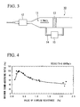
- the value of the airflow resistance is an index or indicator which is defined in JIS (Japanese Industrial Standard) A6306 and which is applied to a flow resistance of a unit area, and is an index measured by using a measurement apparatus as shown in FIG 3.
- a measurement apparatus 10 shown in FIG 3 is roughly constituted from: a channel 11 for flowing air; a flow meter 12 which is arranged on an upper stream side of the channel 11 and which adjusts a flow velocity of the air; a sample 13 (panel main body 4) which is arranged on the way of the cannel 11; a bypass channel 14 which bypasses from an upper stream side to a lower stream side of the sample 13; and a differential pressure gauge 15 which is arranged on the channel 14.
- An airflow velocity at an upper stream side of the sample 13 is set to be 0.5mm/sec.
- the value of the airflow resistance of the panel main body 4 is preferably in the range of 0.1-1.0 Pa, more preferably in the range of 0.15-0.5 Pa, and most preferably in the range of 0.2-0.45 P.
- the value of the airflow resistance of the panel main body 4 is in the range of 0.1-1.0 Pa, it is possible to achieve a 60% or larger maximum sound-absorbing coefficient of the sound-absorbing panel 1, moreover, if the value of the airflow resistance of the panel main body 4 is in the range of 0.15-0.5 Pa, the sound-absorbing coefficient of the sound-absorbing panel 1 can be 80% or larger, and furthermore, if the value of the airflow resistance of the panel main body 4 is in the range of 0.2-0.45 Pa, the sound-absorbing coefficient of the sound-absorbing panel 1 can be 90% or larger.
- FIG. 4 is a graph showing a relationship between maximum sound-absorbing coefficients and the values of the airflow resistance based on measured results of normal incidence sound-absorbing characteristics of the sound-absorbing panels of samples No. 1-25. This FIG. 4 is obtained by plotting the relationship between the maximum sound-absorbing coefficient and the value of the airflow resistance based on measured results of normal incidence sound-absorbing characteristics of 21 kinds of sound absorbing panels which are constituted by laminating, adhering or combining the porous veneer and the porous sound-absorbing base material so as to have the values of resistance of airflow in the range of 0.1-2.2 Pa.
- the maximum sound-absorbing coefficient indicates a maximum value of almost 100% when the value of the airflow resistance is 0.25 Pa.
- the maximum sound-absorbing coefficient is reduced along with an increase of the value of the airflow resistance, and the maximum sound-absorbing coefficient decreases and is approximately 40-50% when the value of the airflow resistance is 2.2 Pa.
- the sound-absorbing panel constituted by arranging both the porous veneer and the porous sound-absorbing base material so as to be overlapped, it is understood that the maximum sound-absorbing coefficient is reduced along with the increase of the value of the airflow resistance. Therefore, it is necessary to provide an upper limit of the value of the airflow resistance to the sound-absorbing panel 1, and the upper limit is 1.0 Pa here.
- the sound-absorbing panel 1 When the sound-absorbing panel 1 is produced, it is sufficient to prepare the porous veneer 2 and the porous sound-absorbing base material 3 and to adhere both of them so as to be overlapped or to detachably attach them along with setting the value of the airflow resistance in the range of 0.1-1.0 Pa.
- a production method can be explained in which a veneer 21 of a thickness in the range of 0.02-0.5 mm is prepared (FIG 5(a)), a masking layer 22 is formed on an overall surface of the veneer 21 as shown in FIG 5(b), and as shown in FICx 5(c), pierced apertures 2b are formed on a portion exposed out of the masking layer 22 by operating EB (Electron Beam) processing, etching or sand blasting.
- EB Electro Beam
- a veneer 31 (FIG. 6(a)) is provided as shown in FIG 6, and next, the pierced apertures 2b are formed by laser machining as shown in FIG 6(b).
- a wood board, a resin board, paper, and the like are preferable as a material of the veneer 31.
- the value of the airflow resistance for example, it is possible to adjust by changing both the constitution of the porous veneer 2 (thickness, aperture diameters of the pierced apertures 2b, aperture ratio) and the constitution of the porous sound-absorbing base material 3 (thickness, percentage of void space, value of the airflow resistance) inside the above-described ranges. Moreover, it is possible to adjust by adhering the porous sound-absorbing base material 3 to the porous veneer 2 and by further adhering other porous sound-absorbing base materials.
- the value of the resistance of airflow of the panel main body 4 is in the range of 0.1-1.0 Pa. Therefore, it is possible to achieve excellent sound-absorbing characteristics.
- the value of the airflow resistance which has a comparatively strong relationship with the maximum sound-absorbing coefficient is used. Therefore, there is no possibility in which there are differences in the maximum sound-absorbing coefficients of the sound-absorbing panels 1 among the products, and it is possible to constitute the sound-absorbing panel 1 with stable sound-absorbing characteristics.
- the value of the airflow resistance of the porous sound-absorbing base material 3 is in the range of 0.1-0.8 Pa. Therefore, when the panel main body 4 is constituted, there is no possibility in which the value of the resistance of airflow of the panel main body 4 is out of the range of 0.1-1.0 Pa, and it is possible to achieve excellent sound-absorbing characteristics.
- porous veneer 2 and the porous sound-absorbing base material 3 are respectively detachable. Therefore, it is possible to easily change or replace only the porous veneer 2 after setting or installing the sound-absorbing panel 1, and it is possible to easily change the design by changing or replacing only the porous veneer 2 in a case in which a design is applied on the porous veneer 2.
- the value of the airflow resistance of the panel main body 4 is set to be 0.1-1.0 Pa. Therefore, it is possible to roughly fix the maximum sound-absorbing coefficient of the sound-absorbing panel 1 at the production steps of the sound-absorbing panel 1, and it is possible to produce the sound-absorbing panels 1 without differences in the sound-absorbing characteristics among the products.
- the sound-absorbing panel 1 of this embodiment it is possible to constitute the panel main body by arranging a supporting base material so as to be overlapped to the porous veneer, and by setting the value of the airflow resistance of the panel main body in the range of 0.1-1.0 Pa. It is possible to apply, for example, a honeycomb constitution material, a punching metal or an expanded metal as the supporting base material.
- the value of the airflow resistance is in the range of 0.1-1.0 Pa. Therefore, it is possible to achieve excellent sound-absorbing characteristics, and it is possible to increase the strength of the sound-absorbing panel because of the supporting base material.
- the sound absorbing panel of the present invention it is possible to provide a backside air layer at the backside of the above-described porous sound-absorbing base material or the above-described supporting base material. By providing the backside air layer, it is possible to further increase the sound-absorbing characteristics.
- a porous veneer which has 30.9% aperture ratio is produced by forming pierced apertures of 70 ⁇ m diameter (0.07 mm) with 0.12 mm intervals between them by applying sandblast on a veneer which is a stainless veneer of 50 ⁇ m (0.05 mm) thickness prepared beforehand and on which design is processed beforehand.
- a glass wool of 50mm thickness product name: glass wool 32K, produced by ASAHI FIBER GLASS Co., Ltd
- the panel main body was formed by adhering this porous sound-absorbing base material to the porous veneer.
- the value of the airflow resistance of the panel main body was 0.3 Pa.
- the sound-absorbing panel of the example 1 is produced in such manner.
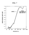
- FIG. 7 shows the results.
- FIG 7 shows normal incidence sound-absorbing characteristics measured in the case of applying only the porous sound-absorbing base material of 50 mm thickness (product name: glass wool 32K, produced by ASAHI FIBER GLASS Co., Ltd) as well.
- the porous veneer was produced in the same manner as the example 1 except for processing an etching on the veneer.
- an aluminum sheet of 1mm thickness (product name: Altone, produced by NICHIAS Corporation) was prepared and the panel main body was formed by adhering this porous sound-absorbing base material to the porous veneer.
- the value of the airflow resistance of the panel main body was 0.2 Pa.
- the sound-absorbing panel of the example 2 is produced in such a manner.
- FIG. 8 shows the results.
- FIG 8 shows normal incidence sound-absorbing characteristics measured in the case of applying only the porous sound-absorbing base material of 1mm thickness (product name: Altone, produced by NICHIAS Corporation) as well.
- a porous veneer which has 30.9% aperture ratio is produced by forming pierced apertures of 70 ⁇ m diameter (0.07 mm) with 0.12 mm intervals between them by applying EB (Electron Beam) processing on a veneer which is a stainless veneer of 50 ⁇ m (0.05 mm) thickness prepared beforehand and on which a design is processed beforehand.
- EB Electro Beam
- an aluminum sheet of 1mm thickness (product name: Altone, produced by NICHIAS Corporation) was prepared and the panel main body was formed by adhering this porous sound-absorbing base material to the porous veneer.
- the value of the airflow resistance of the panel main body was 0.2 Pa.
- the sound-absorbing panel of the example 3 is produced in such manner.
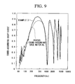
- FIG. 9 shows the results.
- FIG. 9 shows normal incidence sound-absorbing characteristics measured in the case of applying only the porous sound-absorbing base material of 1mm thickness (product name: Altone (registered trademark), produced by NICHIAS Corporation) as well.
- a porous veneer which has 0.9% aperture ratio is produced by forming pierced apertures of 70 ⁇ m diameter (0.07 mm) with 0.7 mm intervals between them by applying laser processing on a veneer which is a PET film of 50 ⁇ m (0.05 mm) thickness prepared beforehand and on which designing is processed beforehand.
- a ceramic particle sintered material of 20 mm thickness product name: cerathone (registered trademark) produced by NGK INSULATORS LTD.
- the value of the airflow resistance of the panel main body was 0.5 Pa.
- the sound-absorbing panel of the example 4 is produced in such a manner.
- FIG 10 shows the results.
- FIG 10 shows normal incidence sound-absorbing characteristics measured in the case of applying only the porous sound-absorbing base material (product name: cerathone (registered trademark) produced by NGK INSULATORS LTD.) as well.
- porous veneers which have 35.4-1.0% aperture ratios are produced by forming pierced apertures of 75 ⁇ m diameter (0.075 mm) with 0.12-0.70 mm intervals between them by applying EB (Electron Beam) processing on a veneer which is a stainless veneer of 50 ⁇ m (0.05 mm) thickness prepared beforehand and on which design is processed beforehand.
- EB Electro Beam
- honeycomb constitution materials product name: paper honeycomb, produced by Showa Aircraft Industry Co., Ltd
- three kinds of panel main bodies are formed by adhering the supporting materials to the respective porous veneers.
- the value of the airflow resistance of the panel main body was 0.01-0.30 Pa.
- the sound-absorbing panels of the examples 5, 6 and the comparative example 1 are produced in a such manner.
- the normal incidence sound-absorbing characteristics of the sound absorbing panels of the examples 5 and 6 are greatly improved over the comparative example 1.
- the aperture ratio of the porous veneer is 35.4% and is comparatively high. Therefore, the value of the airflow resistance is decreased to be 0.01 Pa, and therefore, compared to the examples 5 and 6, the sound-absorbing characteristics are reduced.
- the sound-absorbing panels of the above-described examples 5-6 and the comparative example 1 instead of the honeycomb structure materials, in a case of supporting the backside of the porous veneers by applying punching metals of 0.5mm thickness made from stainless steel which have an aperture ratio of 80% and which have the apertures in approximately lozenge shapes (lengths of diagonal lines are 7mm and 3mm), the sound-absorbing characteristics are measured under a condition of applying the backside air layer of 50mm, and the similar results as the table 2 and the FIG. 11 are obtained.
- Veneers made from paper or stainless steel of 20 ⁇ m (0.02 mm) to 500 ⁇ m (0.5 mm) thickness on which design is processed beforehand are prepared, and seventeen kinds of porous veneers which have 69.4-0.2% aperture ratios produced by forming pierced apertures of 75 ⁇ m (0.075 mm) to 100 ⁇ m (0.1 mm) diameter by applying laser processing on the paper veneer and by applying EB (Electron Beam) processing on the stainless veneer.
- honeycomb constitution materials product name: paper honeycomb, produced by Showa Aircraft Industry Co., Ltd
- the value of the airflow resistance of the panel main body was 0.01-1.5Pa.
- the sound-absorbing panels of the samples No. 26-42 were produced in such a manner.
- FIG 12 is a graph showing a relationship between maximum sound-absorbing coefficients and the values of the airflow resistance based on measured results of normal incidence sound-absorbing characteristics of the sound-absorbing panels of samples No. 26-42.
- a table 3 shows both the constitutions of the sound-absorbing panels and the maximum sound-absorbing coefficients.
- the sound-absorbing coefficient can be 80% or larger, and furthermore, if the value of the airflow resistance is in the range of 0.2-0.45 Pa, the sound-absorbing coefficient can be 90% or larger.
- a porous veneers which have 0.91-10% aperture ratio were produced by forming multiple pierced apertures of 50-200 ⁇ m diameter (0.05-0.2 mm) at regular intervals among them by applying EB (Electron Beam) processing on the veneers which are stainless veneers of 50-100 ⁇ m (0.05-0.1 mm) thickness prepared beforehand and on which design were processed beforehand.
- EB Electro Beam
- porous sound-absorbing base materials a glass wool of 50mm thickness (product name: glass wool 32K, produced by ASAHI FIBER GLASS Co., Ltd) and an aluminum sheet of 1mm thickness (product name: Altone, produced by NICHIAS Corporation) were prepared, and six kinds of panel main bodies were formed by adhering each of the porous sound-absorbing base materials to the porous veneers.
- the values of resistance of airflow of the panel main bodies were 0.29-0.35Pa.
- the sound-absorbing panels of the samples No. 43-48 were produced in such a manner.
- Porous veneers which have 0.91-10.0% aperture ratio were produced by forming multiple pierced apertures of 50-200 ⁇ m diameter (0.05-0.2 mm) at regular intervals among them by processing etching on the veneers which are stainless veneers of 50 ⁇ m (0.05 mm)-100 ⁇ m (0.1 mm) thickness prepared beforehand and on which design were processed beforehand.
- the supporting base materials 3 punching metals of 0.5 mm thickness made from stainless steel which have an aperture ratio of 80% and which have the apertures of 7 mm x 3 mm aperture diameters in approximately lozenge shapes were prepared, and three kinds of the panel main bodies were formed by adhering these supporting base materials to each of the above-described porous veneers.
- the values of resistance of airflow of the panel main bodies were 0.12-0.14 Pa.
- the sound-absorbing panels of the samples No. 49-51 were produced in such a manner.
- Porous veneers which have 2.78% aperture ratio were produced by forming multiple pierced apertures of 75 ⁇ m diameter (0.0 75mm) at regular intervals among them by processing etching on the veneers which are stainless steel, copper and invar alloy veneers of 100 ⁇ m (0.1 mm) thickness prepared beforehand and on which design were processed beforehand.
- porous sound-absorbing base materials glass wools of 50mm thickness (product name: glass wool 32K, produced by ASAHI FIBER GLASS Co., Ltd) were prepared, and three kinds of panel main bodies were formed by respectively adhering porous sound-absorbing base materials to the porous veneers.
- the values of resistance of airflow of the panel main bodies were 0.44-0.46 Pa.
- the sound-absorbing panels of the samples No. 52-54 were produced in such a manner.
- Porous veneers which have 0.91-13.7% aperture ratio were produced by forming multiple pierced apertures of 75 ⁇ m diameter (0.075 mm) at regular intervals among them by applying EB (Electron Beam) processing on the veneers which are stainless steel, copper and invar alloy veneers of 100 ⁇ m (0.1 mm) thickness prepared beforehand and on which designing were processed beforehand.
- EB Electro Beam
- the supporting base materials punching metals of 0.5 mm thickness made from stainless steel which have an aperture ratio of 80% and which have the apertures of 7 mm x 3 mm aperture diameters in approximately lozenge shapes were prepared, and five kinds of the panel main bodies were formed by adhering these supporting base materials to each of the above-described porous veneers.
- the values of resistance of airflow of the panel main bodies were 0.12-0.61 Pa.
- the sound-absorbing panels of the samples No. 55-59 were produced in such a manner.
Landscapes
- Physics & Mathematics (AREA)
- Acoustics & Sound (AREA)
- Engineering & Computer Science (AREA)
- Architecture (AREA)
- Electromagnetism (AREA)
- Civil Engineering (AREA)
- Structural Engineering (AREA)
- Multimedia (AREA)
- Soundproofing, Sound Blocking, And Sound Damping (AREA)
- Building Environments (AREA)
- Devices Affording Protection Of Roads Or Walls For Sound Insulation (AREA)
Abstract
Description
- The present invention relates to a sound-absorbing panel and a production method of the same.
- Priority is claimed on
Japanese Patent Application No. 2006-097002, filed March 31, 2006 Japanese Patent Application No. 2007-001186, filed January 9, 2007 - Conventionally, a sound-absorbing panel constituted from a porous plate, a sound-absorbing panel which has a constitution of combination of both the porous plate and a porous sound-absorbing material are generally known.
Japanese Patent Application No. H06-348281 - Moreover,
Japanese Patent No. 3024525 - Furthermore,
Japanese Patent No. 2993370 - On the other hand, there are many cases in which sound-absorbing panels are used as materials of a wall surface of a building; therefore, not only sound-absorbing characteristics, but also aesthetic appeal or visual appeal of the sound-absorbing panel itself is required.
- However, with respect to the sound-absorbing panel described in
Japanese Patent Application, First Publication No. H06-348281 - Moreover, with respect to the metallic plate disclosed in
Japanese Patent No. 3024525 - Moreover, the sound-absorbing veneer disclosed in
Japanese Patent No. 2993370 - Moreover, with respect to the sound-absorbing plate which is obtained by combining the porous plate and the porous sound-absorbing material as described in
Japanese Patent Application, First Publication No. H06-348281 2993370 - Therefore, there are cases in which there are differences in the maximum sound-absorbing coefficient depending on the state of the constitutional members even though the porous sound-absorbing material of the same percentage of void space is applied; therefore, there are cases in which there are differences in sound-absorbing characteristics even though the sound-absorbing plate has the same constitution.
- The present invention was devised with respect to the above-described backgrounds, and has an object to provide a sound-absorbing panel and a production method of the same which have excellent freedom of design and have small differences in the maximum sound-absorbing coefficients among the products.
- Inventors of the present invention have eagerly studied the relationship between the physical properties of the sound-absorbing panel and the maximum sound-absorbing coefficient, a close relationship was found between the value of the airflow resistance and the maximum sound-absorbing coefficient when the porous veneer and the porous sound-absorbing base material are combined, and a phenomena was found in which an excellent maximum sound-absorbing coefficient is obtained when the value of the airflow resistance is in a specific range.
- In other words, a sound-absorbing panel includes a panel main body, wherein the panel main body includes both a porous veneer of 0.02-0.5 mm thickness which includes pierced apertures of 0.2 mm or smaller aperture diameters or 0.1 mm or smaller aperture diameters, and a porous sound-absorbing base material arranged at a backside of the porous veneer. The panel main body is constituted by arranging the porous veneer and the porous sound-absorbing base material so as to be overlapped. The value of the airflow resistance of the panel main body is in the range of 0.1-1.0 Pa.
- Moreover, it is preferable that, with respect to the above-described sound-absorbing panel, the value of the airflow resistance of the porous sound-absorbing base material be in a range of 0.1-0.8 Pa.
- As another aspect of the present invention, a sound-absorbing panel includes a panel main body, wherein the panel main body includes both a porous veneer of 0.02-0.5 mm thickness which includes pierced apertures of 0.2 mm or smaller aperture diameters or 0.1 mm or smaller aperture diameters, and a supporting base material arranged at the backside of the porous veneer. The panel main body is constituted by arranging the porous veneer and the supporting base material so as to be overlapped. The value of the airflow resistance of the panel main body is in the range of 0.1-1.0 Pa.
- It is preferable that the supporting base material of the above-described sound-absorbing panel be a honeycomb structure material, a punching metal or an expanded metal.
- Moreover, it is preferable that, with respect to the above-described sound-absorbing panel, both the porous veneer and the porous sound-absorbing base material or the supporting base material be detachably attached.
- Moreover, it is preferable that, with respect to the above-described sound-absorbing panel, a backside air layer be provided at the backside of the porous sound-absorbing base material or the supporting base material.
- Next, a production method of a sound-absorbing panel includes the steps of: forming a porous veneer by forming a plurality of pierced apertures of 0.2 mm or smaller aperture diameters or 0.1 mm or smaller aperture diameters on a veneer of 0.02-0.5 mm thickness; and constituting a panel main body by arranging a porous sound-absorbing base material or a supporting base material at the backside of the porous veneer to be overlapped, along with setting a value of the airflow resistance of the panel main body in the range of 0.1-1.0 Pa.
- Moreover, it is preferable that, with respect to the above-described production method of a sound-absorbing panel, a design be applied to a surface of the porous veneer opposite to the backside.
- In accordance with the above-described sound-absorbing panel, the value of resistance of air flow of the panel main body is in the range of 0.1-1.0 Pa. Therefore, it is possible to indicate a 60% or larger maximum sound-absorbing coefficient.
- Moreover, instead of the percentage of void space, the value of the airflow resistance which has a comparatively strong relationship with the maximum sound-absorbing coefficient is used. Therefore, there is no possibility in which there are differences of the maximum sound-absorbing coefficients of the sound-absorbing panels among products, and it is possible to constitute the sound-absorbing panel with stable sound-absorbing characteristics.
- Moreover, the aperture diameter of the pierced aperture is comparatively small. Therefore, the pierced aperture is not conspicuous or an eyesore, and it is possible to freely design the appearance of the sound-absorbing panel without being affected by the pierced aperture.
- Moreover, in accordance with the above-described sound-absorbing panel, the value of the airflow resistance of the porous sound-absorbing base material is in the range of 0.1-0.8 Pa. Therefore, when the panel main body is constituted, there is no possibility in which the value of the resistance of airflow of the panel main body is out of the range of 0.1-1.0 Pa, and it is possible to achieve excellent sound-absorbing characteristics.
- Moreover, if the supporting base material is applied, it is possible to increase the strength of the sound-absorbing panel.
- Moreover, in accordance with the above-described sound-absorbing panel, the porous veneer and the porous sound-absorbing base material or the supporting base material are respectively detachable. Therefore, it is possible to easily change or replace only the porous veneer after setting or installing the sound-absorbing panel, and it is possible to easily change the design by changing or replacing only the porous veneer in a case in which a design is applied on the porous veneer.
- Moreover, in accordance with the production method of the sound-absorbing panel, when the panel main body is constituted by arranging both the porous veneer and the porous sound-absorbing base material so as to be overlapped, the value of the airflow resistance of the panel main body is set to be 0.1-1.0 Pa. Therefore, it is possible to roughly fix the maximum sound-absorbing coefficient of the sound-absorbing panel at the production steps of the sound-absorbing panel, and it is possible to produce the sound-absorbing panels without differences of the sound-absorbing characteristics among the products.
- Moreover, in accordance with the production method of the sound-absorbing panel, a design or decoration is applied on the veneer before forming the porous veneer. Therefore, there is no possibility in which the pierced apertures on the porous veneer are closed or covered by paint and the like used for designing, and it is possible to produce the sound absorbing panel with excellent sound-absorbing characteristics.
-
- FIG. 1 is an outline drawing of a cross-section showing an example of a sound-absorbing panel of an embodiment of the present invention.
- FIG 2 is an outline drawing of a cross-section showing another example of a sound-absorbing panel of an embodiment of the present invention.
- FIG 3 is an outline drawing showing a measuring apparatus of a value of the airflow resistance.
- FIG. 4 is a graph showing a relationship between maximum sound-absorbing coefficients and the values of the airflow resistance based on measured results of normal incidence sound-absorbing characteristics of the sound-absorbing panels of samples No. 1-25.
- FIG 5 is a flow chart showing one example of production steps of a porous veneer.
- FIG 6 is a flow chart showing another example of production steps of the porous veneer.
- FIG 7 is a graph showing the frequency dependency of normal incidence sound-absorbing characteristics of a first embodiment.
- FIG 8 is a graph showing the frequency dependency of normal incidence sound-absorbing characteristics of a second embodiment.
- FIG 9 is a graph showing the frequency dependency of normal incidence sound-absorbing characteristics of a third embodiment.
- FIG 10 is a graph showing the frequency dependency of normal incidence sound-absorbing characteristics of a fourth embodiment.
- FIG 11 is a graph showing the frequency dependency of normal incidence sound-absorbing characteristics of fifth and sixth embodiments and a first comparative example.
- FIG.12 is a graph showing a relationship between maximum sound-absorbing coefficients and the values of the airflow resistance based on measured results of normal incidence sound-absorbing characteristics of the sound-absorbing panels of samples No. 26-42.
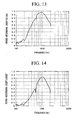
- FIG 13 is a graph showing the frequency dependency of normal incidence sound-absorbing characteristics of a sample No. 44 of an eighth embodiment.
- FIG 14 is a graph showing the frequency dependency of normal incidence sound-absorbing characteristics of a sample No. 50 of a ninth embodiment.
- Hereinafter, a sound-absorbing panel and a production method of the same of the present invention are explained in reference to drawings. The drawings referred to below are used for explaining a constitution of the sound-absorbing panel and the like, and there is possibility in which size, thickness, length, and the like of portions shown in the drawings are different from the physical relationship of the sound-absorbing panel and the like.
- FIG. 1 is an outline drawing of a cross-section showing an example of the sound-absorbing panel of this embodiment, and FIG. 2 is an outline drawing of a cross-section showing another example of the sound-absorbing panel of this embodiment.
- The sound-absorbing panel shown in FIGS. 1 and 2 are constituted from a
porous veneer 2 and a porous sound-absorbingbase material 3 arranged at abackside 2a of theporous veneer 2. A panelmain body 4 is constituted by arranging both theporous veneer 2 and the porous sound-absorbingbase material 3 so as to be overlapped. - The
porous veneer 2 is made from a metallic plate, a wood plate, a resin plate, a sheet of paper, and the like in a range of 0.02-0.5mm thickness, and multiplepierced apertures 2b piercing in the thickness direction which have 0.1mm or smaller aperture diameter or 0.2mm or smaller aperture diameter are provided on theporous veneer 2. Such the multiplepierced apertures 2b are provided. Therefore, it is possible that air and sound pass through theporous veneer 2. Moreover, thepierced apertures 2b have not only a function of passing or transmitting the air and the sound, but also a function of absorbing the sound. The aperture diameters of thepierced apertures 2b are set to be approximately 0.1mm or smaller or 0.2mm or smaller, that is, it is difficult to recognize thepierced apertures 2b by a naked eye, and it is possible to maintain an aesthetically pleasant appearance in theporous veneer 2. - It should be noted that, when the
porous veneer 2 is made from a metallic plate, material can be, for example, stainless steel, aluminum, aluminum alloy, copper, a ferronickel alloy such as invar, and the like. - Moreover, the shape of the
pierced aperture 2b seen on the surface can be a completely circular, an oval shape or rectangular. In the case of a completely circular shape, the aperture diameter is the diameter of the circle, in the case of an oval shape, the aperture diameter is a major axis of the oval, and in a case of the rectangular shape, the aperture diameter is a long side of the rectangle. - Moreover, on a
front surface 2c of theporous veneer 2, in order to improve beauty of the appearance, it is possible to apply a design such as a drawing, a figure, a pattern, or the like, and it is possible to apply a mirror finish on thefront surface 2c. - Moreover, as described above, the thickness of the
porous veneer 2 is preferably in the range of 0.02-0.5 mm. It is not preferable if the thickness is less than 0.02 mm because it is difficult to deal with theporous veneer 2, and it is not preferable if the thickness is larger than 0.5 mm because it is difficult to efficiently form theporous veneer 2. - Moreover, an aperture ratio or an opening ratio of the
pierced apertures 2b is preferably in a range of 0.2-40%, and more preferably in a range of 1-20%. Here, the aperture ratio of thepierced apertures 2b is a ratio of aperture areas of thepierced apertures 2b to an area of thefront surface 2c or theback surface 2a of theporous veneer 2. If the aperture ratio is 0.2% or larger, it is possible to maintain or keep the value of the airflow resistance of theporous veneer 2 itself so as to be 1Pa or smaller, and moreover, it is possible to maintain or keep the value of the airflow resistance of the panelmain body 4 so as to be 1Pa or lower when the panelmain body 4 is constituted by piling up or laminating the porous sound-absorbingbase materials 3 so as to be overlapped. Moreover, if the aperture ratio is 40% or less, the pierced aperture is not conspicuous or an eyesore, and there is no possibility to affect undesirable influence on an aesthetically pleasant appearance of theporous veneer 2. - Next, it is possible that the porous sound-absorbing
base material 3, as shown in FIG. 1, be a granular porous material which is constituted by sintered or binding glass particles, mineral particles, ceramic particles, resin particles, and the like, and moreover, it is possible that the porous sound-absorbingbase material 3, as shown in FIG 2, be a porous material in a fiber state constituted by twining glass fiber, resin fiber, metallic fiber, natural fiber such as cotton, and the like. It is appropriate in a case of applying the granular porous material shown in FIG 1 that a diameter of each particle be approximately 0.1-2 mm. It is appropriate in a case of applying the porous material in a fiber state shown in FIG 2 that glass particles, mineral particles, ceramic particles, resin particles, and the like be filled between the fibers. - A thickness of the porous sound-absorbing
base material 3 is preferably 1mm or thicker, more preferably in the range of 1-50mm, and most preferably in the range of 1-20mm. If the thickness is 1mm or thicker, there is no danger or possibility in which the value of the airflow resistance of the porous sound-absorbingbase material 3 is reduced, and it is possible to increase the value of the airflow resistance of the panelmain body 4 so as to be 0.1 Pa or larger. Moreover, from a viewpoint of sound-absorbing characteristics, there is no limitation on the thickness of the porous sound-absorbingbase material 3. However, from a viewpoint of handling, usability or processing, it is preferable to set the upper limit to be 50mm or thinner. - The percentage of void space of the porous sound-absorbing
base material 3 is preferably in the range of 5-90%, and more preferably in the range of 5-40%. If the percentage of void space is 5% or larger, there is no danger or possibility to severely increase the value of the airflow resistance. Moreover, if the percentage of void space is 90% or smaller, there is no danger or possibility to lose the mechanical strength of the porous sound-absorbingbase material 3. - It should be noted that, as described above, the relationship between the percentage of void space of the porous sound-absorbing
base material 3 and the maximum sound-absorbing coefficient is not uniform or constant. Therefore, if the porous sound-absorbingbase material 3 is selected in reference to the percentage of void space as an index or indicator, it is not necessarily possible to obtain the sound-absorbingpanel 1 which has an excellent maximum sound-absorbing coefficient. Therefore, the percentage of void space can be referred. However, it is not very important. - Next, the value of the airflow resistance of the porous sound-absorbing
base material 3 is preferably in the range of 0.1-0.8 Pa, and more preferably in the range of 0.1-0.3 Pa. If the value of the airflow resistance of the porous sound-absorbingbase material 3 is 0.1Pa or larger, even in a case in which the value of the airflow resistance of theporous veneer 2 is very close to 0Pa it is possible to obtain the value of the airflow resistance of the panelmain body 4 so as to be 0.1Pa or larger. Moreover, if the value of the airflow resistance of the porous sound-absorbingbase material 3 is 0.8Pa or less, even in the case in which the value of the airflow resistance of theporous veneer 2 is a comparatively small value, it is possible to obtain the value of the airflow resistance of the panelmain body 4 so as to be 1Pa or smaller. Moreover, as described below, the sound-absorbing coefficient of the panelmain body 4 indicates 80% or larger when the value of the airflow resistance of the panelmain body 4 is in the range of 0.15-0.5Pa. Therefore, in consideration of an increase by theporous veneer 2, it is more preferable to set the value of the airflow resistance of porous sound-absorbingbase material 3 so as to be 0.3Pa or less. - Furthermore, the surface density of the porous sound-absorbing
base material 3 is preferably 8kg/m2 or smaller from a viewpoint of reducing the weight of the panelmain body 4. - It is possible to adhere both the
porous veneer 2 and the porous sound-absorbingbase material 3 by using an adhesive or to be detachably attached by using metal fittings, a jig, or the like. Especially when they are detachably attached, it is easy to replace theporous veneer 2 and it is possible to change the overall design of theporous veneer 2. - Next, the value of the airflow resistance is explained. The value of the airflow resistance is an index or indicator which is defined in JIS (Japanese Industrial Standard) A6306 and which is applied to a flow resistance of a unit area, and is an index measured by using a measurement apparatus as shown in FIG 3. A
measurement apparatus 10 shown in FIG 3 is roughly constituted from: achannel 11 for flowing air; aflow meter 12 which is arranged on an upper stream side of thechannel 11 and which adjusts a flow velocity of the air; a sample 13 (panel main body 4) which is arranged on the way of thecannel 11; abypass channel 14 which bypasses from an upper stream side to a lower stream side of thesample 13; and adifferential pressure gauge 15 which is arranged on thechannel 14. An airflow velocity at an upper stream side of thesample 13 is set to be 0.5mm/sec. By using themeasurement apparatus 10 constituted in such a manner, a differential pressure indicated by thedifferential pressure gauge 15 is detected and the value of the airflow resistance is measured. - With respect to the sound-absorbing
panel 1 of this embodiment, the value of the airflow resistance of the panelmain body 4 is preferably in the range of 0.1-1.0 Pa, more preferably in the range of 0.15-0.5 Pa, and most preferably in the range of 0.2-0.45 P. If the value of the airflow resistance of the panelmain body 4 is in the range of 0.1-1.0 Pa, it is possible to achieve a 60% or larger maximum sound-absorbing coefficient of the sound-absorbingpanel 1, moreover, if the value of the airflow resistance of the panelmain body 4 is in the range of 0.15-0.5 Pa, the sound-absorbing coefficient of the sound-absorbingpanel 1 can be 80% or larger, and furthermore, if the value of the airflow resistance of the panelmain body 4 is in the range of 0.2-0.45 Pa, the sound-absorbing coefficient of the sound-absorbingpanel 1 can be 90% or larger. - FIG. 4 is a graph showing a relationship between maximum sound-absorbing coefficients and the values of the airflow resistance based on measured results of normal incidence sound-absorbing characteristics of the sound-absorbing panels of samples No. 1-25. This FIG. 4 is obtained by plotting the relationship between the maximum sound-absorbing coefficient and the value of the airflow resistance based on measured results of normal incidence sound-absorbing characteristics of 21 kinds of sound absorbing panels which are constituted by laminating, adhering or combining the porous veneer and the porous sound-absorbing base material so as to have the values of resistance of airflow in the range of 0.1-2.2 Pa. It should be noted that constitutions of the porous veneer (materials, thickness, aperture diameters of the pierced apertures, aperture ratio) and constitutions of the porous sound-absorbing base material (materials, thickness, percentage of void space, value of the airflow resistance) are as shown in Table 1. It should be noted that in Table 1, GW23K, GW32K, GW39K, GW44K, GW51K, GW62K and GW72K are glass wools of ASAHI FIBER GLASS Co., Ltd., Altone (registered trademark) is an aluminum fiber sheet made by NICHIAS Corporation, cerathone (registered trademark) is a ceramic particle sintered material made by NGK INSULATORS LTD..
- As shown in Table 1 and FIG. 4, the maximum sound-absorbing coefficient indicates a maximum value of almost 100% when the value of the airflow resistance is 0.25 Pa. However, the maximum sound-absorbing coefficient is reduced along with an increase of the value of the airflow resistance, and the maximum sound-absorbing coefficient decreases and is approximately 40-50% when the value of the airflow resistance is 2.2 Pa. Thus, with respect to the sound-absorbing panel constituted by arranging both the porous veneer and the porous sound-absorbing base material so as to be overlapped, it is understood that the maximum sound-absorbing coefficient is reduced along with the increase of the value of the airflow resistance. Therefore, it is necessary to provide an upper limit of the value of the airflow resistance to the sound-absorbing
panel 1, and the upper limit is 1.0 Pa here.[Table 1] SAMPLE NO. POROUS VENEER POROUS SOUND-ABSORBING BASE MATERIAL PANEL MATERIAL THICKNESS (µM) APERTURE DIAMETER OF PIERCED APERTURE (µM) APERTURE RATIO (%) MATERIAL THICKNESS (µM) VALUE OF RESISTANCE OF AIRFLOW(PA) VALUE OF RESISTANCE OF AIRFLOW(PA) MAXIMUM SOUND-ABSORBING COEFFICIENT (%) 1 SUS 50 70 30. 9 GW23K 50 0. 17 0.18 99 2 SUS 50 70 30.9 GW32K 50 0.26 0.27 98 3 SUS 50 70 30:9 GW39K 50 0.43 0.44 88 4 SUS 50 70 30.9 GW44K 50 0.51 0.52 82 5 SUS 50 70 30.9 GW51K 50 0.7 0. 72 69 6 SUS 50 70 30.9 GW62K 50 1.07 1. 1 60 7 SUS 50 70 30.9 GW72K 50 2.13 2.14 34 8 SUS 20 70 30.9 GW32K 50 0.26 0.23 96 9 SUS 100 70 30.9 GW32K 50 0.26 0.28 99 10 SUS 500 70 30.9 GW32K 50 0.26 0.46 90 11 SUS 20 70 0.2 GW32K 50 0.26 0.76 70 12 SUS 50 70 0.2 GW32K 50 0.26 2.08 48 13 SUS 50 70 30.9 ALTONE 1 0.16 0.17 87 14 SUS 50 70 3.6 ALTONE 1 0.16 0.46 88 15 SUS 50 70 0.9 ALTONE 1 0.16 0.66 73 16 SUS 50 70 30.9 ALTONE 1 0.16 0.17 87 17 PET 50 70 30.9 CERATHONE 20 0.16 0.26 99 18 PET 50 70 3.6 CERATHONE 20 0.16 0.39 92 19 PET 50 70 0.9 CERATHONE 20 0.16 0.52 88 20 SUS 50 70 40 GW23K 20 0.11 0.11 62 21 PAPER 200 100 0.9 ALTONE 1 0.16 0.76 69 22 WOOD 200 100 0.9 ALTONE 1 0.16 1.02 61 23 WOOD 200 90 0.7 ALTONE 1 0.16 1.13 55 24 SUS 500 70 3.6 ALTONE 1 0.16 2.2 53 25 SUS 50 70 30.9 GW56K 50 0.8 0.82 63 - When the sound-absorbing
panel 1 is produced, it is sufficient to prepare theporous veneer 2 and the porous sound-absorbingbase material 3 and to adhere both of them so as to be overlapped or to detachably attach them along with setting the value of the airflow resistance in the range of 0.1-1.0 Pa. - In order to produce the
porous veneer 2, for example, as shown in FIG. 5, a production method can be explained in which aveneer 21 of a thickness in the range of 0.02-0.5 mm is prepared (FIG 5(a)), amasking layer 22 is formed on an overall surface of theveneer 21 as shown in FIG 5(b), and as shown in FICx 5(c), piercedapertures 2b are formed on a portion exposed out of themasking layer 22 by operating EB (Electron Beam) processing, etching or sand blasting. In this case, it is preferable to apply a metallic plate as a material of theveneer 21. - It is possible to apply another production method in which, first, a veneer 31 (FIG. 6(a)) is provided as shown in FIG 6, and next, the
pierced apertures 2b are formed by laser machining as shown in FIG 6(b). In this case, a wood board, a resin board, paper, and the like are preferable as a material of theveneer 31. - It should be noted that in either case of these two production methods, it is preferable to process designs such as drawings or patterns on the
veneer 21/31 beforehand. - Moreover, with respect to adjustment of the value of the airflow resistance, for example, it is possible to adjust by changing both the constitution of the porous veneer 2 (thickness, aperture diameters of the
pierced apertures 2b, aperture ratio) and the constitution of the porous sound-absorbing base material 3 (thickness, percentage of void space, value of the airflow resistance) inside the above-described ranges. Moreover, it is possible to adjust by adhering the porous sound-absorbingbase material 3 to theporous veneer 2 and by further adhering other porous sound-absorbing base materials. - As described above, in accordance with the sound-absorbing
panel 1, the value of the resistance of airflow of the panelmain body 4 is in the range of 0.1-1.0 Pa. Therefore, it is possible to achieve excellent sound-absorbing characteristics. - Moreover, the value of the airflow resistance which has a comparatively strong relationship with the maximum sound-absorbing coefficient is used. Therefore, there is no possibility in which there are differences in the maximum sound-absorbing coefficients of the sound-absorbing
panels 1 among the products, and it is possible to constitute the sound-absorbingpanel 1 with stable sound-absorbing characteristics. - Moreover, the value of the airflow resistance of the porous sound-absorbing
base material 3 is in the range of 0.1-0.8 Pa. Therefore, when the panelmain body 4 is constituted, there is no possibility in which the value of the resistance of airflow of the panelmain body 4 is out of the range of 0.1-1.0 Pa, and it is possible to achieve excellent sound-absorbing characteristics. - Moreover, the
porous veneer 2 and the porous sound-absorbingbase material 3 are respectively detachable. Therefore, it is possible to easily change or replace only theporous veneer 2 after setting or installing the sound-absorbingpanel 1, and it is possible to easily change the design by changing or replacing only theporous veneer 2 in a case in which a design is applied on theporous veneer 2. - Moreover, in accordance with the above-described production method of the sound-absorbing
panel 1, the value of the airflow resistance of the panelmain body 4 is set to be 0.1-1.0 Pa. Therefore, it is possible to roughly fix the maximum sound-absorbing coefficient of the sound-absorbingpanel 1 at the production steps of the sound-absorbingpanel 1, and it is possible to produce the sound-absorbingpanels 1 without differences in the sound-absorbing characteristics among the products. - Moreover, a design or decoration is applied on the
veneer 21/31 before forming theporous veneer 2. Therefore, there is no possibility in which thepierced apertures 2b on theporous veneer 2 are closed or covered by paint or the like used for design, and it is possible to produce thesound absorbing panel 1 with excellent sound-absorbing characteristics. - Moreover, with respect to the sound-absorbing
panel 1 of this embodiment, it is possible to constitute the panel main body by arranging a supporting base material so as to be overlapped to the porous veneer, and by setting the value of the airflow resistance of the panel main body in the range of 0.1-1.0 Pa. It is possible to apply, for example, a honeycomb constitution material, a punching metal or an expanded metal as the supporting base material. - In accordance with the above-described sound-absorbing panel providing the supporting base material, the value of the airflow resistance is in the range of 0.1-1.0 Pa. Therefore, it is possible to achieve excellent sound-absorbing characteristics, and it is possible to increase the strength of the sound-absorbing panel because of the supporting base material.
- Moreover, with respect to the sound absorbing panel of the present invention, it is possible to provide a backside air layer at the backside of the above-described porous sound-absorbing base material or the above-described supporting base material. By providing the backside air layer, it is possible to further increase the sound-absorbing characteristics.
- A porous veneer which has 30.9% aperture ratio is produced by forming pierced apertures of 70 µm diameter (0.07 mm) with 0.12 mm intervals between them by applying sandblast on a veneer which is a stainless veneer of 50 µm (0.05 mm) thickness prepared beforehand and on which design is processed beforehand.
- Next, as the porous sound-absorbing base material, a glass wool of 50mm thickness (product name: glass wool 32K, produced by ASAHI FIBER GLASS Co., Ltd) was prepared and the panel main body was formed by adhering this porous sound-absorbing base material to the porous veneer. The value of the airflow resistance of the panel main body was 0.3 Pa. The sound-absorbing panel of the example 1 is produced in such manner.
- With respect to the sound-absorbing panel of the example 1, normal incidence sound-absorbing characteristics are measured in the case of setting the thickness of the backside air layer to be 0 mm. FIG. 7 shows the results. FIG 7 shows normal incidence sound-absorbing characteristics measured in the case of applying only the porous sound-absorbing base material of 50 mm thickness (product name: glass wool 32K, produced by ASAHI FIBER GLASS Co., Ltd) as well.
- As shown in FIG 7, compared to the case of applying only the porous sound-absorbing base material, it is recognized that normal incidence sound-absorbing characteristics of the sound-absorbing panel of the example 1 is increased to some degree. The cause of this result is inferred that, compared to the case of applying only the porous sound-absorbing base material, the value of the airflow resistance is increased to some degree by combining the porous sound-absorbing base material and the porous veneer, and therefore, the sound-absorbing characteristics are improved.
- The porous veneer was produced in the same manner as the example 1 except for processing an etching on the veneer.
- Next, as the porous sound-absorbing base material, an aluminum sheet of 1mm thickness (product name: Altone, produced by NICHIAS Corporation) was prepared and the panel main body was formed by adhering this porous sound-absorbing base material to the porous veneer. The value of the airflow resistance of the panel main body was 0.2 Pa. The sound-absorbing panel of the example 2 is produced in such a manner.
- With respect to the sound-absorbing panel of the example 2, normal incidence sound-absorbing characteristics are measured in the case of setting the thickness of the backside air layer to be 150 mm. FIG. 8 shows the results. FIG 8 shows normal incidence sound-absorbing characteristics measured in the case of applying only the porous sound-absorbing base material of 1mm thickness (product name: Altone, produced by NICHIAS Corporation) as well.
- As shown in FIG 8, compared to the case of applying only the porous sound-absorbing base material, it is recognized that normal incidence sound-absorbing characteristics of the sound-absorbing panel of the example 2 is increased to some degree. The cause of this result is inferred that, compared to the case of applying only the porous sound-absorbing base material, the value of the airflow resistance is increased to some degree by combining the porous sound-absorbing base material and the porous veneer, and therefore, the sound-absorbing characteristics are improved as in the first example.
- A porous veneer which has 30.9% aperture ratio is produced by forming pierced apertures of 70µm diameter (0.07 mm) with 0.12 mm intervals between them by applying EB (Electron Beam) processing on a veneer which is a stainless veneer of 50 µm (0.05 mm) thickness prepared beforehand and on which a design is processed beforehand.
- Next, as the porous sound-absorbing base material, an aluminum sheet of 1mm thickness (product name: Altone, produced by NICHIAS Corporation) was prepared and the panel main body was formed by adhering this porous sound-absorbing base material to the porous veneer. The value of the airflow resistance of the panel main body was 0.2 Pa. The sound-absorbing panel of the example 3 is produced in such manner.
- With respect to the sound-absorbing panel of the example 3, normal incidence sound-absorbing characteristics are measured in the case of setting the thickness of the backside air layer to be 150 mm. FIG. 9 shows the results. FIG. 9 shows normal incidence sound-absorbing characteristics measured in the case of applying only the porous sound-absorbing base material of 1mm thickness (product name: Altone (registered trademark), produced by NICHIAS Corporation) as well.
- Same as in the examples 1 and 2, compared to the case of applying only the porous sound-absorbing base material, it is recognized that normal incidence sound-absorbing characteristics of the sound-absorbing panel of the example 3 is increased to some degree. The cause of this result is inferred that, compared to the case of applying only the porous sound-absorbing base material, the value of the airflow resistance is increased to some degree by combining the porous sound-absorbing base material and the porous veneer, and therefore, the sound-absorbing characteristics are improved as in the examples 1 and 2.
- A porous veneer which has 0.9% aperture ratio is produced by forming pierced apertures of 70 µm diameter (0.07 mm) with 0.7 mm intervals between them by applying laser processing on a veneer which is a PET film of 50 µm (0.05 mm) thickness prepared beforehand and on which designing is processed beforehand. Next, as the porous sound-absorbing base material, a ceramic particle sintered material of 20 mm thickness (product name: cerathone (registered trademark) produced by NGK INSULATORS LTD.) was prepared and the panel main body was formed by adhering this porous sound-absorbing base material to the porous veneer. The value of the airflow resistance of the panel main body was 0.5 Pa. The sound-absorbing panel of the example 4 is produced in such a manner.
- With respect to the sound-absorbing panel of the example 4, normal incidence sound-absorbing characteristics are measured in the case of setting the thickness of the backside air layer to be 20 mm. FIG 10 shows the results. FIG 10 shows normal incidence sound-absorbing characteristics measured in the case of applying only the porous sound-absorbing base material (product name: cerathone (registered trademark) produced by NGK INSULATORS LTD.) as well.
- Compared to the case of applying only the porous sound-absorbing base material, it is recognized that normal incidence sound-absorbing characteristics of the sound-absorbing panel of the example 4 is reduced to some degree. Different from examples 1-3, the cause of this result is inferred that, compared to the case of applying only the porous sound-absorbing base material, the value of the airflow resistance is increased to some degree by combining the porous sound-absorbing base material and the porous veneer, and therefore, the sound-absorbing characteristics are reduced.
- Three kinds of porous veneers which have 35.4-1.0% aperture ratios are produced by forming pierced apertures of 75 µm diameter (0.075 mm) with 0.12-0.70 mm intervals between them by applying EB (Electron Beam) processing on a veneer which is a stainless veneer of 50 µm (0.05 mm) thickness prepared beforehand and on which design is processed beforehand.
- Next, honeycomb constitution materials (product name: paper honeycomb, produced by Showa Aircraft Industry Co., Ltd) of 10mm thickness which have cell size of 19mm are prepared, and three kinds of panel main bodies are formed by adhering the supporting materials to the respective porous veneers. The value of the airflow resistance of the panel main body was 0.01-0.30 Pa. The sound-absorbing panels of the examples 5, 6 and the comparative example 1 are produced in a such manner.
- With respect to the sound-absorbing panels of the examples 5, 6 and the comparative example 1, normal incidence sound-absorbing characteristics are measured in the case of setting the thickness of the backside air layers to be 40mm. FIG. 11 shows the results. Moreover, a table 2 shows both the constitutions of the sound-absorbing panels and the maximum sound-absorbing coefficients.
- As shown in FIG 11 and the table 2, it is observed that the normal incidence sound-absorbing characteristics of the sound absorbing panels of the examples 5 and 6 are greatly improved over the comparative example 1. In the comparative example 1, the aperture ratio of the porous veneer is 35.4% and is comparatively high. Therefore, the value of the airflow resistance is decreased to be 0.01 Pa, and therefore, compared to the examples 5 and 6, the sound-absorbing characteristics are reduced.
[Table 2] POROUS VENEER PANEL MATERIAL THICKNESS (µM) APERTURE DIAMETER OF PIERCED APERTURE (µM) INTERVALS BETWEEN PIERCED APERTURES (MM) APERTURE RATIO (%) VALUE OF RESISTANCE OF AIRFLOW(PA) MAXIMUM SOUND-ABSORBING COEFFICIENT (%) COMPARATIVE EXAMPLE 1 SUS 50 75 0.12 35.4 0.01 17 EXAMPLE 5 SUS 50 75 0.35 4.2 0.13 72 EXAMPLE 6 SUS 50 75 0.7 1 0.3 99 - On the other hand, with respect to the sound-absorbing panels of the above-described examples 5-6 and the comparative example 1, instead of the honeycomb structure materials, in a case of supporting the backside of the porous veneers by applying punching metals of 0.5mm thickness made from stainless steel which have an aperture ratio of 80% and which have the apertures in approximately lozenge shapes (lengths of diagonal lines are 7mm and 3mm), the sound-absorbing characteristics are measured under a condition of applying the backside air layer of 50mm, and the similar results as the table 2 and the FIG. 11 are obtained.
- Veneers made from paper or stainless steel of 20 µm (0.02 mm) to 500 µm (0.5 mm) thickness on which design is processed beforehand are prepared, and seventeen kinds of porous veneers which have 69.4-0.2% aperture ratios produced by forming pierced apertures of 75µm (0.075 mm) to 100µm (0.1 mm) diameter by applying laser processing on the paper veneer and by applying EB (Electron Beam) processing on the stainless veneer. Next, honeycomb constitution materials (product name: paper honeycomb, produced by Showa Aircraft Industry Co., Ltd) of 10mm thickness which have cell sizes of 19 mm are prepared, and seventeen kinds of panel main bodies are formed by adhering the supporting materials to the respective porous veneers. The value of the airflow resistance of the panel main body was 0.01-1.5Pa. The sound-absorbing panels of the samples No. 26-42 were produced in such a manner.
- With respect to the sound-absorbing panels of the samples No. 26-42, normal incidence sound-absorbing characteristics are measured in the case of setting the thickness of the backside air layers to be 40 mm in order to measure the maximum sound-absorbing coefficients. FIG 12 is a graph showing a relationship between maximum sound-absorbing coefficients and the values of the airflow resistance based on measured results of normal incidence sound-absorbing characteristics of the sound-absorbing panels of samples No. 26-42. Moreover, a table 3 shows both the constitutions of the sound-absorbing panels and the maximum sound-absorbing coefficients.
[Table 3] POROUS VENEER PANEL SAMPLE NO. MATERIAL THICKNESS (µM) APERTURE DIAMETER OF PIERCED APERTURE (µM) APERTURE RATIO (%) VALUE OF RESISTANCE OF AIRFLOW(PA) MAXIMUM SOUND-ABSORBING COEFFICIENT (%) 26 SUS 50 75 35.4 0.01 17 27 SUS 50 75 4.2 0.13 72 28 PAPER 50 100 1.8 8 0.25 99 29 SUS 50 75 1 0.3 99 30 PAPER 50 75 0.6 0.42 88 31 SUS 50 75 0.4 0.8 68 32 SUS 50 75 0.3 1 60 33 SUS 50 75 0.2 1.5 50 34 SUS 20 75 2.8 0.11 68 35 SUS 20 75 0.9 0.34 93 36 SUS 20 75 0.2 0.9 61 37 SUS 100 75 13.7 0.13 75 38 SUS 100 75 2.8 0.28 98 39 SUS 100 75 0.9 0.75 72 40 SUS 500 75 69.4 0.09 63 41 SUS 500 75 11.1 0.22 98 42 SUS 500 75 4.1 0.82 66 - As shown in the table 3 and FIG. 12, in the cases of constituting the sound-absorbing panels by arranging the porous veneers and the supporting base materials so as to be overlapped, if the value of the airflow resistance is in the range of 0.1-1.0 Pa, it is possible to achieve a 60% or larger maximum sound-absorbing coefficient, moreover, if the value of the airflow resistance is in the range of 0.15-0.5 Pa, the sound-absorbing coefficient can be 80% or larger, and furthermore, if the value of the airflow resistance is in the range of 0.2-0.45 Pa, the sound-absorbing coefficient can be 90% or larger.
- A porous veneers which have 0.91-10% aperture ratio were produced by forming multiple pierced apertures of 50-200 µm diameter (0.05-0.2 mm) at regular intervals among them by applying EB (Electron Beam) processing on the veneers which are stainless veneers of 50-100 µm (0.05-0.1 mm) thickness prepared beforehand and on which design were processed beforehand.
- Next, as the porous sound-absorbing base materials, a glass wool of 50mm thickness (product name: glass wool 32K, produced by ASAHI FIBER GLASS Co., Ltd) and an aluminum sheet of 1mm thickness (product name: Altone, produced by NICHIAS Corporation) were prepared, and six kinds of panel main bodies were formed by adhering each of the porous sound-absorbing base materials to the porous veneers. The values of resistance of airflow of the panel main bodies were 0.29-0.35Pa. The sound-absorbing panels of the samples No. 43-48 were produced in such a manner.
- With respect to the sound-absorbing panels of the samples No. 43-48, normal incidence sound-absorbing characteristics were measured in the case of setting the thickness of the backside air layers to be 50mm in order to measure the maximum sound-absorbing coefficients. A table 4 shows both the constitutions of the sound-absorbing panels and the maximum sound-absorbing coefficients. FIG. 13 shows measured results of the normal incidence sound-absorbing characteristics of the sound-absorbing panel of the sample No. 44.
[Table 4] SAMPLE NO. POROUS VENEER POROUS SOUND-ABSORBING BASE MATERIAL PANEL MATERIAL THICKNESS (µM) APERTURE DIAMETER OF PIERCED (µM) APERTURE (µM) APERTURE RATIO (%) MATERIAL THICKNESS (µM) VALUE OF RESISTANCE OF AIRFLOW(PA) VALUE OF RESISTANCE OF AIRFLOW(PA) MAXIMUM SOUND-ABSORBING COEFFICIENT (%) 43 SUS 100 150 2.04 GW32K 50 0.26 0.3 99 44 SUS 100 200 0.91 GW32K 50 0.26 0.32 97 45 SUS 100 150 2.04 ALTONE 1 0.16 0.3 98 46 SUS 100 200 0.91 ALTONE 1 0.16 0.35 92 47 SUS 50 50 10 GW32K 50 0.26 0.29 98 48 SUS 50 50 10 ALTONE 1 0.16 0.29 98 - As shown in the table 4 and FIG 13, in the cases of applying the porous veneers which have the aperture diameters of 50-200 µm, if the values of resistance of airflow of the panel main bodies are in the range of 0.1-1.0 Pa, it is possible to obtain excellent maximum sound-absorbing coefficients.
- Porous veneers which have 0.91-10.0% aperture ratio were produced by forming multiple pierced apertures of 50-200 µm diameter (0.05-0.2 mm) at regular intervals among them by processing etching on the veneers which are stainless veneers of 50µm (0.05 mm)-100 µm (0.1 mm) thickness prepared beforehand and on which design were processed beforehand.
- Next, as the supporting
base materials 3, punching metals of 0.5 mm thickness made from stainless steel which have an aperture ratio of 80% and which have the apertures of 7 mm x 3 mm aperture diameters in approximately lozenge shapes were prepared, and three kinds of the panel main bodies were formed by adhering these supporting base materials to each of the above-described porous veneers. The values of resistance of airflow of the panel main bodies were 0.12-0.14 Pa. The sound-absorbing panels of the samples No. 49-51 were produced in such a manner. - With respect to the sound-absorbing panels of the samples No. 49-51, normal incidence sound-absorbing characteristics were measured in the case of setting the thickness of the backside air layers to be 50 mm in order to measure the maximum sound-absorbing coefficients. A table 5 shows both the constitutions of the sound-absorbing panels and the maximum sound-absorbing coefficients. FIG 14 shows measured results of the normal incidence sound-absorbing characteristics of the sound-absorbing panel of the sample No. 50.
[Table 5] SAMPLE NO. POROUS VENEER PANEL MATERIAL THICKNESS (µM) APERTURE DIAMETER OF PIERCED APERTURE (µM) APERTURE RATIO (%) VALUE OF RESISTANCE OF AIRFLOW(PA) MAXIMUM SOUND-ABSORBING COEFFICIENT (%) 49 SUS 100 150 2.04 0.12 76 50 SUS 100 200 0.91 0.14 86 51 SUS 50 50 10 0.13 71 - As shown in the table 5 and FIG 14, in the cases of applying the punching metals as the supporting materials, if the values of resistance of airflow of the panel main bodies are in the range of 0.1-1.0 Pa, it is possible to obtain 60% or more maximum sound-absorbing coefficient of the sound-absorbing panel.
- Porous veneers which have 2.78% aperture ratio were produced by forming multiple pierced apertures of 75 µm diameter (0.0 75mm) at regular intervals among them by processing etching on the veneers which are stainless steel, copper and invar alloy veneers of 100 µm (0.1 mm) thickness prepared beforehand and on which design were processed beforehand.
- Next, as the porous sound-absorbing base materials, glass wools of 50mm thickness (product name: glass wool 32K, produced by ASAHI FIBER GLASS Co., Ltd) were prepared, and three kinds of panel main bodies were formed by respectively adhering porous sound-absorbing base materials to the porous veneers. The values of resistance of airflow of the panel main bodies were 0.44-0.46 Pa. The sound-absorbing panels of the samples No. 52-54 were produced in such a manner.
- With respect to the sound-absorbing panels of the samples No. 52-54, normal incidence sound-absorbing characteristics were measured in the case of setting the thickness of the backside air layers to be 50 mm in order to measure the maximum sound-absorbing coefficients. A table 6 shows both the constitutions of the sound-absorbing panels and the maximum sound-absorbing coefficients.
[Table 6] SAMPLE NO. POROUS VENEER POROUS SOUND-ABSORBING BASE MATERIAL PANEL MATERIAL THICKNESS (µM) APERTURE DIAMETER OF PIERCED APERTURE (µM) APERTURE RATIO (%) MATERIAL THICKNESS (µM) VALUE OF RESISTANCE OF AIRFLOW(PA) VALUE OF RESISTANCE OF AIRFLOW(PA) MAXIMUM SOUND-ABSORBING COEFFICIENT (%) 52 ALMINJUM 100 75 2. 78 GW32K 50 0.26 0.46 92 53 COPPER 100 75 2. 78 GW32K 50 0.26 0.45 94 54 INVAR 100 75 2.78 GW32K 50 0.26 0.44 91 - As shown in the table 6, in the cases of applying aluminum, copper or invar as the material of the porous veneers, if the values of resistance of airflow of the panel main bodies are in the range of 0.1-1.0 Pa, it is possible to obtain 60% or more maximum sound-absorbing coefficient of the sound-absorbing panel.
- Porous veneers which have 0.91-13.7% aperture ratio were produced by forming multiple pierced apertures of 75 µm diameter (0.075 mm) at regular intervals among them by applying EB (Electron Beam) processing on the veneers which are stainless steel, copper and invar alloy veneers of 100 µm (0.1 mm) thickness prepared beforehand and on which designing were processed beforehand.
- Next, as the supporting base materials, punching metals of 0.5 mm thickness made from stainless steel which have an aperture ratio of 80% and which have the apertures of 7 mm x 3 mm aperture diameters in approximately lozenge shapes were prepared, and five kinds of the panel main bodies were formed by adhering these supporting base materials to each of the above-described porous veneers. The values of resistance of airflow of the panel main bodies were 0.12-0.61 Pa. The sound-absorbing panels of the samples No. 55-59 were produced in such a manner.
- With respect to the sound-absorbing panels of the samples No. 55-59, normal incidence sound-absorbing characteristics were measured in the case of setting the thickness of the backside air layers to be 50 mm in order to measure the maximum sound-absorbing coefficients. A table 7 shows both the constitutions of the sound-absorbing panels and the maximum sound-absorbing coefficients.
[Table 7] SAMPLE NO. POROUS VENEER PANEL MATERIAL THICKNESS (µM) APERTURE DIAMETER OF PIERCED APERTURE (µM) APERTURE RATIO (%) VALUE OF RESISTANCE OF AIRFLOW(PA) MAXIMUM SOUND-ABSORBING COEFFICIENT (%) 55 ALUMINIUM 100 75 13.7 0.12 73 56 ALUMINIUM 100 75 2. 78 0.24 99 57 ALUMINIUM 100 75 0.91 0.61 76 58 COPPER 100 75 2.78 0.25 98 59 INVAR 100 75 2. 78 0.24 97 - As shown in the table 7, in the cases of applying aluminum, copper or invar as the material of the porous veneers and applying the punching metals as the supporting base materials, if the values of resistance of airflow of the panel main bodies are in the range of 0.1-1.0 Pa, it is possible to obtain 60% or more maximum sound-absorbing coefficient of the sound-absorbing panel.
- In accordance with the present invention, it is possible to provide a sound-absorbing panel and a production method of the same which have excellent freedom of design and have less difference in the maximum sound-absorbing coefficients among the products.
- While preferred embodiments of the invention have been described and illustrated above, it should be understood that these are exemplary of the invention and are not to be considered as limiting. Additions, omissions, substitutions, and other modifications can be made without departing from the spirit or scope of the present invention. Accordingly, the invention is not to be considered as being limited by the foregoing description, and is only limited by the scope of the appended claims.
Claims (8)
- A sound-absorbing panel comprising a panel main body, wherein:the panel main body comprises:a porous veneer of 0.02-0.5 mm thickness which comprises pierced apertures of 0.2 mm or smaller aperture diameters or 0.1mm or smaller aperture diameters; anda porous sound-absorbing base material arranged at a backside of the porous veneer;the panel main body is constituted by arranging the porous veneer and the porous sound-absorbing base material to be overlapped; anda value of airflow resistance of the panel main body is in a range of 0.1-1.0 Pa.
- A sound-absorbing panel according to claim 1, wherein a value of airflow resistance of the porous sound-absorbing base material is in a range of 0.1-0.8 Pa.
- Asound-absorbing panel comprising a panel main body, wherein:the panel main body comprises:a porous veneer of 0.02-0.5 mm thickness which comprises pierced apertures of 0.2mm or smaller aperture diameters or 0.1 mm or smaller aperture diameters; anda supporting base material arranged at a backside of the porous veneer;the panel main body is constituted by arranging the porous veneer and the supporting base material to be overlapped; anda value of airflow resistance of the panel main body is in a range of 0.1-1.0 Pa.
- A sound-absorbing panel according to claim 3, wherein the supporting base material is a honeycomb structure material or a punching metal or an expanded metal.
- A sound-absorbing panel according to claim 1, wherein both the porous veneer and the porous sound-absorbing base material are detachably attached.
- A sound-absorbing panel according to claim 3, wherein both the porous veneer and the porous sound-absorbing base material are detachably attached.
- A production method of a sound-absorbing panel comprising the steps of:forming a porous veneer by forming a plurality of pierced apertures of 0.2 mm or smaller aperture diameters or 0.1 mm or smaller aperture diameters on a veneer of 0.02-0.5 mm thickness; andconstituting a panel main body by arranging a porous sound-absorbing base material or a supporting base material at a backside of the porous veneer to be overlapped, along with setting a value of airflow resistance of the panel main body in a range of 0.1-1.0 Pa.
- A production method of a sound-absorbing panel according to claim 7, wherein a design is applied to a surface of the porous veneer opposite to the backside.
Applications Claiming Priority (2)
| Application Number | Priority Date | Filing Date | Title |
|---|---|---|---|
| JP2006097002 | 2006-03-31 | ||
| JP2007001186A JP2007291834A (en) | 2006-03-31 | 2007-01-09 | Sound absorbing panel and method of manufacturing sound absorbing panel |
Publications (3)
| Publication Number | Publication Date |
|---|---|
| EP1840287A2 true EP1840287A2 (en) | 2007-10-03 |
| EP1840287A3 EP1840287A3 (en) | 2010-10-06 |
| EP1840287B1 EP1840287B1 (en) | 2014-03-12 |
Family
ID=37964790
Family Applications (1)
| Application Number | Title | Priority Date | Filing Date |
|---|---|---|---|
| EP07006601.4A Not-in-force EP1840287B1 (en) | 2006-03-31 | 2007-03-29 | Sound-absorbing panel of porous material and production method of the same |
Country Status (4)
| Country | Link |
|---|---|
| US (1) | US7600609B2 (en) |
| EP (1) | EP1840287B1 (en) |
| JP (1) | JP2007291834A (en) |
| CN (1) | CN101046111B (en) |
Cited By (10)
| Publication number | Priority date | Publication date | Assignee | Title |
|---|---|---|---|---|
| EP2055850A1 (en) * | 2007-11-05 | 2009-05-06 | Rockwool International A/S | Acoustic absorbing panel provided with a decorative design pattern and a method and apparatus for manufacturing the panel |
| EP2333766A4 (en) * | 2008-10-02 | 2012-04-04 | Nagoya Oil Chemical Co Ltd | ACOUSTIC ABSORPTION MATERIAL, MULTILAYER ACOUSTIC ABSORPTION MATERIAL, MULTILAYER ACOUSTIC ABSORPTION MOLDED MATERIAL, ACOUSTIC ABSORPTION INTERIOR MATERIAL, AND ACOUSTIC FLOORING ABSORPTION MATERIAL |
| CZ304840B6 (en) * | 2013-12-02 | 2014-11-26 | Josef Žikovský | Transparent slot-coupled cavity of road traffic noise reducing barrier |
| CN104213669A (en) * | 2014-08-15 | 2014-12-17 | 成都宏源铸造材料有限公司 | Workshop sound-absorbing wall |
| US9224379B2 (en) | 2011-08-25 | 2015-12-29 | 3M Innovative Properties Company | Acoustic decorative material |
| EP2871638A4 (en) * | 2012-07-05 | 2016-02-17 | Lg Hausys Ltd | INTERNAL SOUND ABSORPTION SHEET AND SOUNDS AND SOUND ABSORPTION PANEL CONTAINING SAME |
| RU2639594C2 (en) * | 2012-09-17 | 2017-12-21 | Хп Пельцер Холдинг Гмбх | Multilayer perforated sound absorber |
| CN108489855A (en) * | 2018-04-12 | 2018-09-04 | 合肥工业大学 | A kind of sound-absorbing material flow resistance measuring instrument of temperature-controllable |
| EP3605525A4 (en) * | 2017-03-27 | 2020-03-25 | FUJIFILM Corporation | SOUNDPROOFING STRUCTURE, SOUND ABSORBING PANEL AND ADJUSTMENT PANEL |
| CN112681582A (en) * | 2020-12-23 | 2021-04-20 | 澳莆(上海)环保科技有限公司 | Sound module is inhaled to indoor A level fire prevention bamboo veneer curtain |
Families Citing this family (32)
| Publication number | Priority date | Publication date | Assignee | Title |
|---|---|---|---|---|
| US7743880B2 (en) * | 2005-03-30 | 2010-06-29 | Panasonic Corporation | Sound absorbing structure |
| DE202005008921U1 (en) * | 2005-06-07 | 2005-08-11 | Rieter Technologies Ag | Acoustically effective hybrid underfloor lining for vehicles has shape-stabilizing region with thermoplastic, elastomer or duroplastic material; acoustically effective region material is embedded in shape -stabilizing region material |
| DE102007000568A1 (en) * | 2007-10-24 | 2009-04-30 | Silencesolutions Gmbh | sound absorber |
| JP6029279B2 (en) * | 2008-04-14 | 2016-11-24 | スリーエム イノベイティブ プロパティズ カンパニー | Multi-layer sound absorbing sheet |
| US8133357B2 (en) * | 2008-04-18 | 2012-03-13 | Usg Interiors, Inc. | Panels including renewable components and methods for manufacturing same |
| CN102077272B (en) * | 2008-04-22 | 2014-09-10 | 3M创新有限公司 | Hybrid sound absorbing sheet |
| KR20160055954A (en) * | 2008-05-05 | 2016-05-18 | 쓰리엠 이노베이티브 프로퍼티즈 컴파니 | Acoustic composite |
| BRPI0913579A2 (en) * | 2008-05-22 | 2015-11-24 | 3M Innovative Properties Co | sound-absorbing multilayer structure comprising mesh layer |
| DE102009006166B4 (en) * | 2009-01-26 | 2012-12-13 | Airbus Operations Gmbh | Method and system for producing a composite panel |
| FR2953973A1 (en) * | 2009-12-11 | 2011-06-17 | Aircelle Sa | ACOUSTIC PANEL MANUFACTURING METHOD FOR AN AIRCRAFT NACELLE |
| CN102477718A (en) * | 2010-11-29 | 2012-05-30 | 张家港港丰交通安全设施有限公司 | Highway acoustic celotex board |
| FI123952B (en) * | 2011-01-12 | 2014-01-15 | Acoustic Group Oy | Coating and its preparation process |
| JP5956786B2 (en) * | 2012-03-05 | 2016-07-27 | 株式会社クラレ | SOUND ABSORBING PANEL, SOUND ABSORPING METHOD, AND SOUND IMPROVING METHOD |
| WO2014006896A1 (en) * | 2012-07-04 | 2014-01-09 | 西川ゴム工業株式会社 | Soundproof material |
| WO2014010551A1 (en) * | 2012-07-12 | 2014-01-16 | 豊和繊維工業株式会社 | Soundproofing body and insulator for automobile |
| US8720642B1 (en) * | 2012-12-12 | 2014-05-13 | Wilfried Beckervordersandforth | Acoustic element and method for producing an acoustic element |
| CN104269166A (en) * | 2014-10-11 | 2015-01-07 | 国家电网公司 | Dual-layer three-dimensional noise reduction protection screen |
| JP6539850B2 (en) * | 2014-12-12 | 2019-07-10 | 昭和電工株式会社 | Method of manufacturing structure |
| CN104805930B (en) * | 2015-04-14 | 2017-06-13 | 国网河南省电力公司济源供电公司 | A kind of transformer station's antinoise wall and construction method |
| JP6495094B2 (en) * | 2015-05-19 | 2019-04-03 | 株式会社神戸製鋼所 | Perforated plate |
| JP6663659B2 (en) * | 2015-07-14 | 2020-03-13 | 大成建設株式会社 | Size setting method of through hole of perforated sound absorbing board that constitutes sound absorbing structure |
| JP6352336B2 (en) * | 2015-11-27 | 2018-07-04 | 株式会社神戸製鋼所 | Porous sound absorbing plate |
| GB201521075D0 (en) * | 2015-11-30 | 2016-01-13 | Short Brothers Plc | Methods, precursors and abrasive blasting masks for manufacturing noise attenuating devices |
| EP3438969B1 (en) * | 2016-03-29 | 2022-04-06 | FUJIFILM Corporation | Soundproofing structure, partition structure, window member, and cage |
| CN105822137A (en) * | 2016-05-05 | 2016-08-03 | 成都华气能源工程有限公司 | Temporary sound-insulation protective screen with rolling wheels |
| CN111052225A (en) * | 2017-08-28 | 2020-04-21 | 富士胶片株式会社 | Sound insulation structure and sound insulation structure |
| US10810988B2 (en) * | 2017-12-01 | 2020-10-20 | Spirit Aerosystems, Inc. | Acoustic panel employing rounded particles in septum layer and system and method for making same |
| CN108357186A (en) * | 2018-03-17 | 2018-08-03 | 侯炳林 | A kind of production technology of acoustic decoration board |
| US10837169B2 (en) * | 2019-03-14 | 2020-11-17 | Hilti Aktiengesellschaft | Method and apparatus for producing a tubular sealing element |
| CN112012117A (en) * | 2020-09-16 | 2020-12-01 | 曾发英 | Temperature-change sound insulation barrier for road |
| DE102021200905A1 (en) * | 2021-02-01 | 2022-08-04 | Fraunhofer-Gesellschaft zur Förderung der angewandten Forschung eingetragener Verein | Multi-layer sound absorption panel and its use as well as method and device for its manufacture |
| CN112976747A (en) * | 2021-04-29 | 2021-06-18 | 中国空气动力研究与发展中心低速空气动力研究所 | Noise elimination structure with composite protective panel |
Family Cites Families (16)
| Publication number | Priority date | Publication date | Assignee | Title |
|---|---|---|---|---|
| US4235303A (en) * | 1978-11-20 | 1980-11-25 | The Boeing Company | Combination bulk absorber-honeycomb acoustic panels |
| JPH0521119Y2 (en) * | 1987-06-09 | 1993-05-31 | ||
| CN2036551U (en) * | 1988-08-30 | 1989-04-26 | 北京清河毛纺织厂 | Cloud-drift-like sound-absorbing slab |
| US5041323A (en) * | 1989-10-26 | 1991-08-20 | Rohr Industries, Inc. | Honeycomb noise attenuation structure |
| JPH06348281A (en) | 1993-06-03 | 1994-12-22 | Ndc Co Ltd | Sound absorbing board and its production |
| JP2993370B2 (en) * | 1994-05-30 | 1999-12-20 | ヤマハ株式会社 | Sound absorbing decorative board |
| JP3024525B2 (en) | 1995-09-28 | 2000-03-21 | 住友金属工業株式会社 | Surface metal plate and sound damping structural member for reducing sound wave reflectance |
| JPH09101788A (en) * | 1995-10-04 | 1997-04-15 | Nippon Steel Chem Co Ltd | Sound absorbing material and its manufacturing method |
| DE29911495U1 (en) * | 1998-10-06 | 1999-09-02 | Lignoform Benken Ag, Benken | Sound absorbing plate for interior design |
| US6182787B1 (en) * | 1999-01-12 | 2001-02-06 | General Electric Company | Rigid sandwich panel acoustic treatment |
| US6345688B1 (en) * | 1999-11-23 | 2002-02-12 | Johnson Controls Technology Company | Method and apparatus for absorbing sound |
| GB0016149D0 (en) * | 2000-06-30 | 2000-08-23 | Short Brothers Plc | A noise attenuation panel |
| JP2002173914A (en) * | 2000-12-08 | 2002-06-21 | Nippon Sheet Glass Co Ltd | Sound absorbing plate |
| CN2501932Y (en) * | 2001-08-15 | 2002-07-24 | 北新建材(集团)有限公司 | Mineral wool board with noise eliminating function |
| DE10253832A1 (en) * | 2002-11-18 | 2004-05-27 | Carcoustics Tech Center Gmbh | Sound absorbing heat shield for motor vehicles to protect chassis from heat, and suppress sound emitted by exhaust silencers is formed entirely of aluminum materials. |
| US7540354B2 (en) * | 2006-05-26 | 2009-06-02 | United Technologies Corporation | Micro-perforated acoustic liner |
-
2007
- 2007-01-09 JP JP2007001186A patent/JP2007291834A/en active Pending
- 2007-03-28 CN CN2007100914281A patent/CN101046111B/en not_active Expired - Fee Related
- 2007-03-29 EP EP07006601.4A patent/EP1840287B1/en not_active Not-in-force
- 2007-03-29 US US11/730,050 patent/US7600609B2/en not_active Expired - Fee Related
Cited By (14)
| Publication number | Priority date | Publication date | Assignee | Title |
|---|---|---|---|---|
| WO2009059993A1 (en) * | 2007-11-05 | 2009-05-14 | Rockwool International A/S | Acoustic absorbing panel provided with a decorative design pattern and a method and apparatus for manufacturing the panel |
| EP2055850A1 (en) * | 2007-11-05 | 2009-05-06 | Rockwool International A/S | Acoustic absorbing panel provided with a decorative design pattern and a method and apparatus for manufacturing the panel |
| EP2333766A4 (en) * | 2008-10-02 | 2012-04-04 | Nagoya Oil Chemical Co Ltd | ACOUSTIC ABSORPTION MATERIAL, MULTILAYER ACOUSTIC ABSORPTION MATERIAL, MULTILAYER ACOUSTIC ABSORPTION MOLDED MATERIAL, ACOUSTIC ABSORPTION INTERIOR MATERIAL, AND ACOUSTIC FLOORING ABSORPTION MATERIAL |
| US9224379B2 (en) | 2011-08-25 | 2015-12-29 | 3M Innovative Properties Company | Acoustic decorative material |
| US9416532B2 (en) | 2012-07-05 | 2016-08-16 | Lg Hausys, Ltd. | Interior sound absorption sheet and sound absorbing sound-proofing panel containing same |
| EP2871638A4 (en) * | 2012-07-05 | 2016-02-17 | Lg Hausys Ltd | INTERNAL SOUND ABSORPTION SHEET AND SOUNDS AND SOUND ABSORPTION PANEL CONTAINING SAME |
| RU2639594C2 (en) * | 2012-09-17 | 2017-12-21 | Хп Пельцер Холдинг Гмбх | Multilayer perforated sound absorber |
| CZ304840B6 (en) * | 2013-12-02 | 2014-11-26 | Josef Žikovský | Transparent slot-coupled cavity of road traffic noise reducing barrier |
| CN104213669A (en) * | 2014-08-15 | 2014-12-17 | 成都宏源铸造材料有限公司 | Workshop sound-absorbing wall |
| EP3605525A4 (en) * | 2017-03-27 | 2020-03-25 | FUJIFILM Corporation | SOUNDPROOFING STRUCTURE, SOUND ABSORBING PANEL AND ADJUSTMENT PANEL |
| US10988924B2 (en) * | 2017-03-27 | 2021-04-27 | Fujifilm Corporation | Soundproof structure, sound absorbing panel, and sound adjusting panel |
| CN108489855A (en) * | 2018-04-12 | 2018-09-04 | 合肥工业大学 | A kind of sound-absorbing material flow resistance measuring instrument of temperature-controllable |
| CN108489855B (en) * | 2018-04-12 | 2023-12-05 | 合肥工业大学 | A temperature-controlled sound-absorbing material flow resistance measuring instrument |
| CN112681582A (en) * | 2020-12-23 | 2021-04-20 | 澳莆(上海)环保科技有限公司 | Sound module is inhaled to indoor A level fire prevention bamboo veneer curtain |
Also Published As
| Publication number | Publication date |
|---|---|
| EP1840287B1 (en) | 2014-03-12 |
| EP1840287A3 (en) | 2010-10-06 |
| CN101046111B (en) | 2010-10-13 |
| CN101046111A (en) | 2007-10-03 |
| US7600609B2 (en) | 2009-10-13 |
| US20070227815A1 (en) | 2007-10-04 |
| JP2007291834A (en) | 2007-11-08 |
Similar Documents
| Publication | Publication Date | Title |
|---|---|---|
| EP1840287B1 (en) | Sound-absorbing panel of porous material and production method of the same | |
| EP0509166B1 (en) | Honeycomb noise attenuation structure | |
| US4433021A (en) | Sound attenuation sandwich panel including barrier material for corrosion control | |
| EP2026325B1 (en) | Linear acoustic liner | |
| EP2871638B1 (en) | Interior sound absorption sheet and sound absorbing sound-proofing panel containing same | |
| TW200730353A (en) | Composite magnetic thin sheet and method of manufacturing the same | |
| EP1837861A2 (en) | Sound-absorbing material, production method of the same, and sound-absorbing-panel | |
| JP6663659B2 (en) | Size setting method of through hole of perforated sound absorbing board that constitutes sound absorbing structure | |
| EP2221156B1 (en) | Die for forming honeycomb structure | |
| AU2017232173A1 (en) | Gypsum composites used in fire resistant building components | |
| JP6872529B2 (en) | How to make a multi-layer textile structure to protect an acoustic device, how to make a component to protect an acoustic device with a multi-layer textile structure, and the resulting acoustic device protection component | |
| EP2105272A2 (en) | Honeycomb structure-forming die and method for manufacturing the same | |
| CH700728B1 (en) | Acoustic elements. | |
| JP6110851B2 (en) | Die for forming honeycomb structure and method for manufacturing the same | |
| EP1798310A3 (en) | Cemented carbide inserts for wear demanding parting and grooving in heat resistant super alloys (HRSA) and stainless steels | |
| CA2957338A1 (en) | System, method and apparatus for gypsum board with embedded structure having open cells that are substantially filled | |
| WO1992009988A1 (en) | Improvements in attenuators | |
| AU746503B2 (en) | Heat resistant product and method | |
| Nabavi et al. | A novel method for manufacturing of aluminum foam sandwich panels | |
| EP2429863B1 (en) | Sound-absorbing heat shield | |
| JP2005281759A (en) | Super high pressure sintered structure, ultra high pressure composite sintered structure, manufacturing method thereof, and cutting tool | |
| JP2006106423A (en) | Sound-absorbing material and sound-absorbing panel | |
| JPH0278536A (en) | Core for sandwich panel, only to edge face of which resin is adhered | |
| JP2004250735A (en) | Composite structure | |
| EP1409239B1 (en) | Method of manufacturing surface element, and surface element |
Legal Events
| Date | Code | Title | Description |
|---|---|---|---|
| PUAI | Public reference made under article 153(3) epc to a published international application that has entered the european phase |
Free format text: ORIGINAL CODE: 0009012 |
|
| AK | Designated contracting states |
Kind code of ref document: A2 Designated state(s): AT BE BG CH CY CZ DE DK EE ES FI FR GB GR HU IE IS IT LI LT LU LV MC MT NL PL PT RO SE SI SK TR |
|
| AX | Request for extension of the european patent |
Extension state: AL BA HR MK YU |
|
| PUAL | Search report despatched |
Free format text: ORIGINAL CODE: 0009013 |
|
| AK | Designated contracting states |
Kind code of ref document: A3 Designated state(s): AT BE BG CH CY CZ DE DK EE ES FI FR GB GR HU IE IS IT LI LT LU LV MC MT NL PL PT RO SE SI SK TR |
|
| AX | Request for extension of the european patent |
Extension state: AL BA HR MK RS |
|
| 17P | Request for examination filed |
Effective date: 20110406 |
|
| AKX | Designation fees paid |
Designated state(s): AT BE BG CH CY CZ DE DK EE ES FI FR GB GR HU IE IS IT LI LT LU LV MC MT NL PL PT RO SE SI SK TR |
|
| GRAP | Despatch of communication of intention to grant a patent |
Free format text: ORIGINAL CODE: EPIDOSNIGR1 |
|
| RIC1 | Information provided on ipc code assigned before grant |
Ipc: G10K 11/162 20060101ALI20130904BHEP Ipc: E04B 1/86 20060101AFI20130904BHEP Ipc: E04B 1/84 20060101ALI20130904BHEP |
|
| INTG | Intention to grant announced |
Effective date: 20130926 |
|
| GRAS | Grant fee paid |
Free format text: ORIGINAL CODE: EPIDOSNIGR3 |
|
| GRAA | (expected) grant |
Free format text: ORIGINAL CODE: 0009210 |
|
| AK | Designated contracting states |
Kind code of ref document: B1 Designated state(s): AT BE BG CH CY CZ DE DK EE ES FI FR GB GR HU IE IS IT LI LT LU LV MC MT NL PL PT RO SE SI SK TR |
|
| REG | Reference to a national code |
Ref country code: GB Ref legal event code: FG4D |
|
| REG | Reference to a national code |
Ref country code: CH Ref legal event code: EP |
|
| REG | Reference to a national code |
Ref country code: AT Ref legal event code: REF Ref document number: 656442 Country of ref document: AT Kind code of ref document: T Effective date: 20140315 |
|
| REG | Reference to a national code |
Ref country code: IE Ref legal event code: FG4D |
|
| REG | Reference to a national code |
Ref country code: DE Ref legal event code: R096 Ref document number: 602007035470 Country of ref document: DE Effective date: 20140424 |
|
| REG | Reference to a national code |
Ref country code: NL Ref legal event code: VDEP Effective date: 20140312 |
|
| PG25 | Lapsed in a contracting state [announced via postgrant information from national office to epo] |
Ref country code: LT Free format text: LAPSE BECAUSE OF FAILURE TO SUBMIT A TRANSLATION OF THE DESCRIPTION OR TO PAY THE FEE WITHIN THE PRESCRIBED TIME-LIMIT Effective date: 20140312 |
|
| REG | Reference to a national code |
Ref country code: AT Ref legal event code: MK05 Ref document number: 656442 Country of ref document: AT Kind code of ref document: T Effective date: 20140312 |
|
| REG | Reference to a national code |
Ref country code: LT Ref legal event code: MG4D |
|
| PG25 | Lapsed in a contracting state [announced via postgrant information from national office to epo] |
Ref country code: FI Free format text: LAPSE BECAUSE OF FAILURE TO SUBMIT A TRANSLATION OF THE DESCRIPTION OR TO PAY THE FEE WITHIN THE PRESCRIBED TIME-LIMIT Effective date: 20140312 Ref country code: CY Free format text: LAPSE BECAUSE OF FAILURE TO SUBMIT A TRANSLATION OF THE DESCRIPTION OR TO PAY THE FEE WITHIN THE PRESCRIBED TIME-LIMIT Effective date: 20140312 Ref country code: SE Free format text: LAPSE BECAUSE OF FAILURE TO SUBMIT A TRANSLATION OF THE DESCRIPTION OR TO PAY THE FEE WITHIN THE PRESCRIBED TIME-LIMIT Effective date: 20140312 |
|
| PG25 | Lapsed in a contracting state [announced via postgrant information from national office to epo] |
Ref country code: LV Free format text: LAPSE BECAUSE OF FAILURE TO SUBMIT A TRANSLATION OF THE DESCRIPTION OR TO PAY THE FEE WITHIN THE PRESCRIBED TIME-LIMIT Effective date: 20140312 |
|
| PG25 | Lapsed in a contracting state [announced via postgrant information from national office to epo] |
Ref country code: NL Free format text: LAPSE BECAUSE OF FAILURE TO SUBMIT A TRANSLATION OF THE DESCRIPTION OR TO PAY THE FEE WITHIN THE PRESCRIBED TIME-LIMIT Effective date: 20140312 Ref country code: CZ Free format text: LAPSE BECAUSE OF FAILURE TO SUBMIT A TRANSLATION OF THE DESCRIPTION OR TO PAY THE FEE WITHIN THE PRESCRIBED TIME-LIMIT Effective date: 20140312 Ref country code: BE Free format text: LAPSE BECAUSE OF FAILURE TO SUBMIT A TRANSLATION OF THE DESCRIPTION OR TO PAY THE FEE WITHIN THE PRESCRIBED TIME-LIMIT Effective date: 20140312 Ref country code: RO Free format text: LAPSE BECAUSE OF FAILURE TO SUBMIT A TRANSLATION OF THE DESCRIPTION OR TO PAY THE FEE WITHIN THE PRESCRIBED TIME-LIMIT Effective date: 20140312 Ref country code: IS Free format text: LAPSE BECAUSE OF FAILURE TO SUBMIT A TRANSLATION OF THE DESCRIPTION OR TO PAY THE FEE WITHIN THE PRESCRIBED TIME-LIMIT Effective date: 20140712 Ref country code: EE Free format text: LAPSE BECAUSE OF FAILURE TO SUBMIT A TRANSLATION OF THE DESCRIPTION OR TO PAY THE FEE WITHIN THE PRESCRIBED TIME-LIMIT Effective date: 20140312 Ref country code: BG Free format text: LAPSE BECAUSE OF FAILURE TO SUBMIT A TRANSLATION OF THE DESCRIPTION OR TO PAY THE FEE WITHIN THE PRESCRIBED TIME-LIMIT Effective date: 20140612 |
|
| REG | Reference to a national code |
Ref country code: CH Ref legal event code: PL |
|
| PG25 | Lapsed in a contracting state [announced via postgrant information from national office to epo] |
Ref country code: PL Free format text: LAPSE BECAUSE OF FAILURE TO SUBMIT A TRANSLATION OF THE DESCRIPTION OR TO PAY THE FEE WITHIN THE PRESCRIBED TIME-LIMIT Effective date: 20140312 Ref country code: SK Free format text: LAPSE BECAUSE OF FAILURE TO SUBMIT A TRANSLATION OF THE DESCRIPTION OR TO PAY THE FEE WITHIN THE PRESCRIBED TIME-LIMIT Effective date: 20140312 Ref country code: ES Free format text: LAPSE BECAUSE OF FAILURE TO SUBMIT A TRANSLATION OF THE DESCRIPTION OR TO PAY THE FEE WITHIN THE PRESCRIBED TIME-LIMIT Effective date: 20140312 Ref country code: AT Free format text: LAPSE BECAUSE OF FAILURE TO SUBMIT A TRANSLATION OF THE DESCRIPTION OR TO PAY THE FEE WITHIN THE PRESCRIBED TIME-LIMIT Effective date: 20140312 |
|
| REG | Reference to a national code |
Ref country code: DE Ref legal event code: R097 Ref document number: 602007035470 Country of ref document: DE |
|
| PG25 | Lapsed in a contracting state [announced via postgrant information from national office to epo] |
Ref country code: PT Free format text: LAPSE BECAUSE OF FAILURE TO SUBMIT A TRANSLATION OF THE DESCRIPTION OR TO PAY THE FEE WITHIN THE PRESCRIBED TIME-LIMIT Effective date: 20140714 |
|
| REG | Reference to a national code |
Ref country code: IE Ref legal event code: MM4A |
|
| PLBE | No opposition filed within time limit |
Free format text: ORIGINAL CODE: 0009261 |
|
| STAA | Information on the status of an ep patent application or granted ep patent |
Free format text: STATUS: NO OPPOSITION FILED WITHIN TIME LIMIT |
|
| PG25 | Lapsed in a contracting state [announced via postgrant information from national office to epo] |
Ref country code: MC Free format text: LAPSE BECAUSE OF FAILURE TO SUBMIT A TRANSLATION OF THE DESCRIPTION OR TO PAY THE FEE WITHIN THE PRESCRIBED TIME-LIMIT Effective date: 20140312 Ref country code: CH Free format text: LAPSE BECAUSE OF NON-PAYMENT OF DUE FEES Effective date: 20140331 Ref country code: DK Free format text: LAPSE BECAUSE OF FAILURE TO SUBMIT A TRANSLATION OF THE DESCRIPTION OR TO PAY THE FEE WITHIN THE PRESCRIBED TIME-LIMIT Effective date: 20140312 Ref country code: LI Free format text: LAPSE BECAUSE OF NON-PAYMENT OF DUE FEES Effective date: 20140331 Ref country code: IE Free format text: LAPSE BECAUSE OF NON-PAYMENT OF DUE FEES Effective date: 20140329 |
|
| 26N | No opposition filed |
Effective date: 20141215 |
|
| GBPC | Gb: european patent ceased through non-payment of renewal fee |
Effective date: 20140612 |
|
| REG | Reference to a national code |
Ref country code: DE Ref legal event code: R097 Ref document number: 602007035470 Country of ref document: DE Effective date: 20141215 |
|
| PG25 | Lapsed in a contracting state [announced via postgrant information from national office to epo] |
Ref country code: IT Free format text: LAPSE BECAUSE OF FAILURE TO SUBMIT A TRANSLATION OF THE DESCRIPTION OR TO PAY THE FEE WITHIN THE PRESCRIBED TIME-LIMIT Effective date: 20140312 |
|
| PG25 | Lapsed in a contracting state [announced via postgrant information from national office to epo] |
Ref country code: GB Free format text: LAPSE BECAUSE OF NON-PAYMENT OF DUE FEES Effective date: 20140612 |
|
| PG25 | Lapsed in a contracting state [announced via postgrant information from national office to epo] |
Ref country code: SI Free format text: LAPSE BECAUSE OF FAILURE TO SUBMIT A TRANSLATION OF THE DESCRIPTION OR TO PAY THE FEE WITHIN THE PRESCRIBED TIME-LIMIT Effective date: 20140312 |
|
| REG | Reference to a national code |
Ref country code: FR Ref legal event code: PLFP Year of fee payment: 10 |
|
| PG25 | Lapsed in a contracting state [announced via postgrant information from national office to epo] |
Ref country code: MT Free format text: LAPSE BECAUSE OF FAILURE TO SUBMIT A TRANSLATION OF THE DESCRIPTION OR TO PAY THE FEE WITHIN THE PRESCRIBED TIME-LIMIT Effective date: 20140312 |
|
| PGFP | Annual fee paid to national office [announced via postgrant information from national office to epo] |
Ref country code: DE Payment date: 20160322 Year of fee payment: 10 |
|
| PGFP | Annual fee paid to national office [announced via postgrant information from national office to epo] |
Ref country code: FR Payment date: 20160208 Year of fee payment: 10 |
|
| PG25 | Lapsed in a contracting state [announced via postgrant information from national office to epo] |
Ref country code: GR Free format text: LAPSE BECAUSE OF FAILURE TO SUBMIT A TRANSLATION OF THE DESCRIPTION OR TO PAY THE FEE WITHIN THE PRESCRIBED TIME-LIMIT Effective date: 20140613 |
|
| PG25 | Lapsed in a contracting state [announced via postgrant information from national office to epo] |
Ref country code: TR Free format text: LAPSE BECAUSE OF FAILURE TO SUBMIT A TRANSLATION OF THE DESCRIPTION OR TO PAY THE FEE WITHIN THE PRESCRIBED TIME-LIMIT Effective date: 20140312 Ref country code: LU Free format text: LAPSE BECAUSE OF NON-PAYMENT OF DUE FEES Effective date: 20140329 Ref country code: HU Free format text: LAPSE BECAUSE OF FAILURE TO SUBMIT A TRANSLATION OF THE DESCRIPTION OR TO PAY THE FEE WITHIN THE PRESCRIBED TIME-LIMIT; INVALID AB INITIO Effective date: 20070329 |
|
| REG | Reference to a national code |
Ref country code: DE Ref legal event code: R119 Ref document number: 602007035470 Country of ref document: DE |
|
| REG | Reference to a national code |
Ref country code: FR Ref legal event code: ST Effective date: 20171130 |
|
| PG25 | Lapsed in a contracting state [announced via postgrant information from national office to epo] |
Ref country code: DE Free format text: LAPSE BECAUSE OF NON-PAYMENT OF DUE FEES Effective date: 20171003 Ref country code: FR Free format text: LAPSE BECAUSE OF NON-PAYMENT OF DUE FEES Effective date: 20170331 |