EP1840038A1 - A collapsible container - Google Patents
A collapsible container Download PDFInfo
- Publication number
- EP1840038A1 EP1840038A1 EP07004099A EP07004099A EP1840038A1 EP 1840038 A1 EP1840038 A1 EP 1840038A1 EP 07004099 A EP07004099 A EP 07004099A EP 07004099 A EP07004099 A EP 07004099A EP 1840038 A1 EP1840038 A1 EP 1840038A1
- Authority
- EP
- European Patent Office
- Prior art keywords
- wall
- container according
- foregoing
- container
- bottom wall
- Prior art date
- Legal status (The legal status is an assumption and is not a legal conclusion. Google has not performed a legal analysis and makes no representation as to the accuracy of the status listed.)
- Granted
Links
Images





Classifications
-
- B—PERFORMING OPERATIONS; TRANSPORTING
- B65—CONVEYING; PACKING; STORING; HANDLING THIN OR FILAMENTARY MATERIAL
- B65D—CONTAINERS FOR STORAGE OR TRANSPORT OF ARTICLES OR MATERIALS, e.g. BAGS, BARRELS, BOTTLES, BOXES, CANS, CARTONS, CRATES, DRUMS, JARS, TANKS, HOPPERS, FORWARDING CONTAINERS; ACCESSORIES, CLOSURES, OR FITTINGS THEREFOR; PACKAGING ELEMENTS; PACKAGES
- B65D19/00—Pallets or like platforms, with or without side walls, for supporting loads to be lifted or lowered
- B65D19/02—Rigid pallets with side walls, e.g. box pallets
- B65D19/06—Rigid pallets with side walls, e.g. box pallets with bodies formed by uniting or interconnecting two or more components
- B65D19/18—Rigid pallets with side walls, e.g. box pallets with bodies formed by uniting or interconnecting two or more components made wholly or mainly of plastics material
-
- B—PERFORMING OPERATIONS; TRANSPORTING
- B65—CONVEYING; PACKING; STORING; HANDLING THIN OR FILAMENTARY MATERIAL
- B65D—CONTAINERS FOR STORAGE OR TRANSPORT OF ARTICLES OR MATERIALS, e.g. BAGS, BARRELS, BOTTLES, BOXES, CANS, CARTONS, CRATES, DRUMS, JARS, TANKS, HOPPERS, FORWARDING CONTAINERS; ACCESSORIES, CLOSURES, OR FITTINGS THEREFOR; PACKAGING ELEMENTS; PACKAGES
- B65D2519/00—Pallets or like platforms, with or without side walls, for supporting loads to be lifted or lowered
- B65D2519/00004—Details relating to pallets
- B65D2519/00009—Materials
- B65D2519/00014—Materials for the load supporting surface
- B65D2519/00034—Plastic
-
- B—PERFORMING OPERATIONS; TRANSPORTING
- B65—CONVEYING; PACKING; STORING; HANDLING THIN OR FILAMENTARY MATERIAL
- B65D—CONTAINERS FOR STORAGE OR TRANSPORT OF ARTICLES OR MATERIALS, e.g. BAGS, BARRELS, BOTTLES, BOXES, CANS, CARTONS, CRATES, DRUMS, JARS, TANKS, HOPPERS, FORWARDING CONTAINERS; ACCESSORIES, CLOSURES, OR FITTINGS THEREFOR; PACKAGING ELEMENTS; PACKAGES
- B65D2519/00—Pallets or like platforms, with or without side walls, for supporting loads to be lifted or lowered
- B65D2519/00004—Details relating to pallets
- B65D2519/00009—Materials
- B65D2519/00049—Materials for the base surface
- B65D2519/00069—Plastic
-
- B—PERFORMING OPERATIONS; TRANSPORTING
- B65—CONVEYING; PACKING; STORING; HANDLING THIN OR FILAMENTARY MATERIAL
- B65D—CONTAINERS FOR STORAGE OR TRANSPORT OF ARTICLES OR MATERIALS, e.g. BAGS, BARRELS, BOTTLES, BOXES, CANS, CARTONS, CRATES, DRUMS, JARS, TANKS, HOPPERS, FORWARDING CONTAINERS; ACCESSORIES, CLOSURES, OR FITTINGS THEREFOR; PACKAGING ELEMENTS; PACKAGES
- B65D2519/00—Pallets or like platforms, with or without side walls, for supporting loads to be lifted or lowered
- B65D2519/00004—Details relating to pallets
- B65D2519/00009—Materials
- B65D2519/00154—Materials for the side walls
- B65D2519/00174—Plastic
-
- B—PERFORMING OPERATIONS; TRANSPORTING
- B65—CONVEYING; PACKING; STORING; HANDLING THIN OR FILAMENTARY MATERIAL
- B65D—CONTAINERS FOR STORAGE OR TRANSPORT OF ARTICLES OR MATERIALS, e.g. BAGS, BARRELS, BOTTLES, BOXES, CANS, CARTONS, CRATES, DRUMS, JARS, TANKS, HOPPERS, FORWARDING CONTAINERS; ACCESSORIES, CLOSURES, OR FITTINGS THEREFOR; PACKAGING ELEMENTS; PACKAGES
- B65D2519/00—Pallets or like platforms, with or without side walls, for supporting loads to be lifted or lowered
- B65D2519/00004—Details relating to pallets
- B65D2519/00258—Overall construction
- B65D2519/00263—Overall construction of the pallet
- B65D2519/00268—Overall construction of the pallet made of one piece
-
- B—PERFORMING OPERATIONS; TRANSPORTING
- B65—CONVEYING; PACKING; STORING; HANDLING THIN OR FILAMENTARY MATERIAL
- B65D—CONTAINERS FOR STORAGE OR TRANSPORT OF ARTICLES OR MATERIALS, e.g. BAGS, BARRELS, BOTTLES, BOXES, CANS, CARTONS, CRATES, DRUMS, JARS, TANKS, HOPPERS, FORWARDING CONTAINERS; ACCESSORIES, CLOSURES, OR FITTINGS THEREFOR; PACKAGING ELEMENTS; PACKAGES
- B65D2519/00—Pallets or like platforms, with or without side walls, for supporting loads to be lifted or lowered
- B65D2519/00004—Details relating to pallets
- B65D2519/00258—Overall construction
- B65D2519/00283—Overall construction of the load supporting surface
- B65D2519/00288—Overall construction of the load supporting surface made of one piece
-
- B—PERFORMING OPERATIONS; TRANSPORTING
- B65—CONVEYING; PACKING; STORING; HANDLING THIN OR FILAMENTARY MATERIAL
- B65D—CONTAINERS FOR STORAGE OR TRANSPORT OF ARTICLES OR MATERIALS, e.g. BAGS, BARRELS, BOTTLES, BOXES, CANS, CARTONS, CRATES, DRUMS, JARS, TANKS, HOPPERS, FORWARDING CONTAINERS; ACCESSORIES, CLOSURES, OR FITTINGS THEREFOR; PACKAGING ELEMENTS; PACKAGES
- B65D2519/00—Pallets or like platforms, with or without side walls, for supporting loads to be lifted or lowered
- B65D2519/00004—Details relating to pallets
- B65D2519/00258—Overall construction
- B65D2519/00313—Overall construction of the base surface
- B65D2519/00318—Overall construction of the base surface made of one piece
-
- B—PERFORMING OPERATIONS; TRANSPORTING
- B65—CONVEYING; PACKING; STORING; HANDLING THIN OR FILAMENTARY MATERIAL
- B65D—CONTAINERS FOR STORAGE OR TRANSPORT OF ARTICLES OR MATERIALS, e.g. BAGS, BARRELS, BOTTLES, BOXES, CANS, CARTONS, CRATES, DRUMS, JARS, TANKS, HOPPERS, FORWARDING CONTAINERS; ACCESSORIES, CLOSURES, OR FITTINGS THEREFOR; PACKAGING ELEMENTS; PACKAGES
- B65D2519/00—Pallets or like platforms, with or without side walls, for supporting loads to be lifted or lowered
- B65D2519/00004—Details relating to pallets
- B65D2519/00258—Overall construction
- B65D2519/00313—Overall construction of the base surface
- B65D2519/00328—Overall construction of the base surface shape of the contact surface of the base
- B65D2519/00338—Overall construction of the base surface shape of the contact surface of the base contact surface having a discrete foot-like shape
-
- B—PERFORMING OPERATIONS; TRANSPORTING
- B65—CONVEYING; PACKING; STORING; HANDLING THIN OR FILAMENTARY MATERIAL
- B65D—CONTAINERS FOR STORAGE OR TRANSPORT OF ARTICLES OR MATERIALS, e.g. BAGS, BARRELS, BOTTLES, BOXES, CANS, CARTONS, CRATES, DRUMS, JARS, TANKS, HOPPERS, FORWARDING CONTAINERS; ACCESSORIES, CLOSURES, OR FITTINGS THEREFOR; PACKAGING ELEMENTS; PACKAGES
- B65D2519/00—Pallets or like platforms, with or without side walls, for supporting loads to be lifted or lowered
- B65D2519/00004—Details relating to pallets
- B65D2519/00258—Overall construction
- B65D2519/00492—Overall construction of the side walls
- B65D2519/00497—Overall construction of the side walls whereby at least one side wall is made of one piece
-
- B—PERFORMING OPERATIONS; TRANSPORTING
- B65—CONVEYING; PACKING; STORING; HANDLING THIN OR FILAMENTARY MATERIAL
- B65D—CONTAINERS FOR STORAGE OR TRANSPORT OF ARTICLES OR MATERIALS, e.g. BAGS, BARRELS, BOTTLES, BOXES, CANS, CARTONS, CRATES, DRUMS, JARS, TANKS, HOPPERS, FORWARDING CONTAINERS; ACCESSORIES, CLOSURES, OR FITTINGS THEREFOR; PACKAGING ELEMENTS; PACKAGES
- B65D2519/00—Pallets or like platforms, with or without side walls, for supporting loads to be lifted or lowered
- B65D2519/00004—Details relating to pallets
- B65D2519/00547—Connections
- B65D2519/00577—Connections structures connecting side walls, including corner posts, to each other
- B65D2519/00582—Connections structures connecting side walls, including corner posts, to each other structures intended to be disassembled, i.e. collapsible or dismountable
- B65D2519/00587—Connections structures connecting side walls, including corner posts, to each other structures intended to be disassembled, i.e. collapsible or dismountable side walls directly connected to each other
-
- B—PERFORMING OPERATIONS; TRANSPORTING
- B65—CONVEYING; PACKING; STORING; HANDLING THIN OR FILAMENTARY MATERIAL
- B65D—CONTAINERS FOR STORAGE OR TRANSPORT OF ARTICLES OR MATERIALS, e.g. BAGS, BARRELS, BOTTLES, BOXES, CANS, CARTONS, CRATES, DRUMS, JARS, TANKS, HOPPERS, FORWARDING CONTAINERS; ACCESSORIES, CLOSURES, OR FITTINGS THEREFOR; PACKAGING ELEMENTS; PACKAGES
- B65D2519/00—Pallets or like platforms, with or without side walls, for supporting loads to be lifted or lowered
- B65D2519/00004—Details relating to pallets
- B65D2519/00547—Connections
- B65D2519/00636—Connections structures connecting side walls to the pallet
- B65D2519/00641—Structures intended to be disassembled
- B65D2519/00646—Structures intended to be disassembled by means of hinges
- B65D2519/00656—Structures intended to be disassembled by means of hinges separately formed
-
- B—PERFORMING OPERATIONS; TRANSPORTING
- B65—CONVEYING; PACKING; STORING; HANDLING THIN OR FILAMENTARY MATERIAL
- B65D—CONTAINERS FOR STORAGE OR TRANSPORT OF ARTICLES OR MATERIALS, e.g. BAGS, BARRELS, BOTTLES, BOXES, CANS, CARTONS, CRATES, DRUMS, JARS, TANKS, HOPPERS, FORWARDING CONTAINERS; ACCESSORIES, CLOSURES, OR FITTINGS THEREFOR; PACKAGING ELEMENTS; PACKAGES
- B65D2519/00—Pallets or like platforms, with or without side walls, for supporting loads to be lifted or lowered
- B65D2519/00004—Details relating to pallets
- B65D2519/00736—Details
- B65D2519/00865—Collapsible, i.e. at least two constitutive elements remaining hingedly connected
- B65D2519/00875—Collapsible, i.e. at least two constitutive elements remaining hingedly connected collapsible side walls
- B65D2519/009—Collapsible, i.e. at least two constitutive elements remaining hingedly connected collapsible side walls whereby all side walls are hingedly connected to the base panel
Definitions
- This invention relates to a container, in particular a box of the type with collapsible walls.
- Collapsible boxes of several kind comprise a bottom wall or base and a plurality of side walls mounted on the bottom wall and movable between an erect, containment position and a folded, rest position in which its size is reduced.
- the need is also felt for a container or box with collapsible walls that is inexpensive to manufacture.
- the trade also feels the need for a container or box with collapsible walls that can be quickly and easily assembled from its individual component parts.
- This invention therefore provides a container, in particular a box of the type with collapsible walls, comprising a bottom wall and a plurality of side walls mounted on the bottom wall and movable between an erect, containment position and a folded, rest position, characterised in that at least one end side wall, when in the erect position, can be moved from an engaged containment position to a disengaged position in which it can be moved to the folded position.
- the container in particular in the form of a box - having components made of moulded plastic - is particularly suitable for transporting fruit and vegetable products and is of the type with collapsible walls, that is to say, walls that can be folded so that the box, when empty, occupies a minimum of space and can be conveniently transported or stored.
- the container, or box, 10 comprises a base, or bottom wall, 12 and a plurality of side walls comprising opposite pairs of walls, referred to herein as first and second end walls 14 and 16, each constituting a short side of the box, and first and second longitudinal walls, of which only one, labelled 18, is illustrated in the accompanying drawings, constituting the long sides of the box.
- first and second end walls 14 and 16 each constituting a short side of the box
- first and second longitudinal walls of which only one, labelled 18, is illustrated in the accompanying drawings, constituting the long sides of the box.
- the side containment walls 14, 16 and 18 are mounted on the bottom wall, or base, 12 and are mobile, relative to the latter, between an erect position for containing the product, and a folded rest position in which the container itself can be transported or stored.
- the base 12 comprises a wall, defining a substantially flat upper surface 12', and a plurality of supporting feet, or, more specifically, three feet 13 at each longitudinal side of the box, and short longitudinal protrusions in the form of short side walls 112, 112, comprising means for coupling to the longitudinal walls 18.
- the short coupling walls 112 protrude upwardly from the product supporting surface 12' in the opposite direction to that in which the supporting feet 13 extend.
- the invention contemplates the provision of a first and a second side end wall 14 and 16 which, when in the respective erect position, can advantageously be moved between a lowered position (shown in Figure 10), where each of these walls is engaged or locked, suitable for containing the product, and a raised position, where each of these walls is disengaged and free to move towards the folded, rest position, shown in Figure 11.
- each of the end walls 14, 16 comprises a part, that defines an upper downwardly hook-shaped portion 20 which, as shown in Figure 1, is adapted for coupling to a respective upwardly extending protrusion 22 provided on the end 18a, 18b of the respective longitudinal wall 18.
- the end walls 14 and 16 when the longitudinal walls 18 are in the open, or erect, condition, the end walls 14 and 16, also in the erect containment condition, can be coupled to the longitudinal walls by a downward movement from the raised position - allowing free rotation to the folded condition - to a lowered position in which the respective hooking element 20 engages a corresponding portion 22 provided at the curved end 18a, 18b of the respective longitudinal wall 18.
- the hook-shaped portion 20 and the protrusion 22 can be disengaged by an upward movement of the end wall 14, 16 relative to the longitudinal walls 18.
- each longitudinal wall 18 comprises at the bottom of it a plurality of protrusions 24, defining fork-like elements 26, designed to engage respective pins 28 at recesses 30 made in the side walls 112 of the base 12, thus constituting advantageous means for turning the longitudinal walls about the pins 28.
- Means are also advantageously provided for turning the end wall of the container.
- the means for turning the side wall of the container are designed to turn the side wall relative to the bottom wall 12, in particular, from the disengaged, erect position to the rest position or from the rest position to the erect position.
- the means for turning the end wall of the container comprise respective pins 32, distributed along the end wall, and elongated slotted means 34, illustrated individually in Figure 9, into which the pin 32 is inserted in freely slidable manner in a vertical direction or according to the long side of the slot 34.
- the pin 32 extends transversally at a bottom end of the mobile wall 16, and in particular, extends from corresponding opposite vertical walls, or faces, labelled 33, defining a respective recess 35 at the bottom of the mobile wall 16.
- the slotted means 34 in turn comprise respective tabs 38, 40 which can be moved elastically towards and away from each other and which extend from the bottom wall 12 of the container with which they are associated at holes, labelled 42, open at the top.
- these elastically spreading tabs 38, 40 comprise respective teeth 44, 46, which face outwards and which, in use, cooperate with corresponding bottom retaining surfaces 48, 50, at respective openings 42 made at the edge of the upper surface of the container base 12.
- the slotted body 34 also has protruding tabs 38, 40 each having a respective enlarged portion which, as shown in the scaled-up view of Figure 15, extends towards the other tab.
- These inwardly protruding portions of the tabs 38, 40 are labelled 38a and 40a and with their upper edge delimit the bottom of the respective slot 34'.
- the moulded plastic components of the container can easily be assembled by snapping the tabs 38, 40 onto the respective pin 32 in such a way as to insert the pin 32 into the slot opening 34' between the tabs and then inserting the tabs 38, 40 into the respective opening 42 in such a way as to engage the outward facing teeth 44, 46 with the respective retaining surfaces 48, 50.
- the elongated slot 34' extends vertically and is defined at the top by a curved end 34'a from which there extend opposing longitudinal sliding surfaces 34'b, 34'c for the pin 32 and, at the bottom, by the upper surfaces 34'd and 34'e of the aforementioned inner protrusions 38a, 40a.
- Means 42, 54 are advantageously provided for guiding the mobile walls 14, 16 as they turn from the erect position to the lowered rest position and vice versa.
- these means for guiding the turning movement of the mobile walls 14 and 16 comprise a curved surface 52, protruding downwardly from the respective mobile wall 14, 16, said curved surface being slidable against a corresponding surface 54, which protrudes upwardly from the bottom wall 12 and which is well illustrated in Figure 4.
- the curved surface 52 for guiding the turning movement of the mobile walls 14, 16 is eccentric with respect to the rotation pin 32 and is adapted to define a larger diameter or distance at the pin 32, on the longitudinal extension of the pin 32, and a smaller diameter or width in the direction transversal to the pin 32.
- a section of the outside profile of the cam-like surface 52 coincides, on the inside, with the outside profile of the respective wall 33, which delimits the recess 35 that houses the rotation pin 32, while on the outside, the cam-like surface 52 affords a substantially longitudinal, or vertical, surface 52b that is recessed with respect to the profile of the respective wall 33, in such a way that - when the wall 16 is erect, or vertical - the cam 52 can pass under the sliding protrusion 54, thereby allowing the wall 16 to move from the disengaged, free-turning upper position to the engaged lower position where it is locked to the bottom 12.
- Means are advantageously provided for retaining the respective end walls 14, 16 in the erect lowered containment position.
- These retaining means comprise a vertical wall 60 extending from the guide protrusion 54 and acting in conjunction with the corresponding longitudinal surface 52b of the cam-like protrusion 52.
- the coupling pins 28 of the longitudinal walls 18 are located at a level above the level corresponding to the coupling area of the end walls 14, 16 so as to enable positioning above the latter in the folded condition of the container.
- each end wall has lower transversal surfaces 116' between corresponding areas for the pin 32 and corresponding areas for the rotation surfaces 52, constituting means for abutting against the upper surface 37' of protrusions 37 made between the corresponding slot 34 insertion areas and the corresponding areas occupied by the guide protrusions 54, as well illustrated in Figure 4.
- the longitudinal walls 18 can be opened by turning them about the rotation pins 28 from the lowered position, parallel to the bottom 12 of the container, to a position in which the walls 18 are positioned vertically, and the corresponding end walls 14, 16 then lifted in the direction opposite that described above, until the container walls are in the erect position shown in Figure 11 and then easily pushed down in order to engage the coupling element 20 of the respective end wall with the corresponding coupling portions 22 on the longitudinal walls 18 of the container.
- the container according to the invention may be made in any desired size.
- it may have a rectangular base 12 with the long side 1200 mm long and the short side 800 mm long, or the long side 800 mm long and the short side 600 mm, so that two smaller boxes placed on top of one another will exactly match the size of a larger box.
- the boxes are thus very handy to transport.
- the short collapsible walls of one size are interchangeable with the long collapsible walls of the other size. These walls are 800 mm long in both cases.
- the same collapsible end walls can be used to make containers of different sizes.
Landscapes
- Engineering & Computer Science (AREA)
- Mechanical Engineering (AREA)
- Rigid Containers With Two Or More Constituent Elements (AREA)
- Packages (AREA)
- Containers And Packaging Bodies Having A Special Means To Remove Contents (AREA)
Abstract
Description
- This invention relates to a container, in particular a box of the type with collapsible walls.
- Collapsible boxes of several kind are known. These boxes, as a whole, comprise a bottom wall or base and a plurality of side walls mounted on the bottom wall and movable between an erect, containment position and a folded, rest position in which its size is reduced.
- In the field, however, there is a need for a collapsible box or container which is more practical than existing containers of this kind and whose walls can be moved more quickly and easily from the erect containment position to the folded, reduced size position and vice versa.
- According to another aspect, the need is also felt for a container or box with collapsible walls that is inexpensive to manufacture.
- According to yet another aspect, the trade also feels the need for a container or box with collapsible walls that can be quickly and easily assembled from its individual component parts.
- This invention therefore provides a container, in particular a box of the type with collapsible walls, comprising a bottom wall and a plurality of side walls mounted on the bottom wall and movable between an erect, containment position and a folded, rest position, characterised in that at least one end side wall, when in the erect position, can be moved from an engaged containment position to a disengaged position in which it can be moved to the folded position.
- Thus, once the respective collapsible wall has been disengaged so that it can move freely to the folded, rest position, it can be moved to this rest position with a quick and easy movement.
- These and other features of the invention are clearly described in the claims below and its advantages are more apparent from the detailed description which follows, with reference to the accompanying drawings which illustrate a preferred embodiment of the invention provided merely by way of example without restricting the scope of the inventive concept.
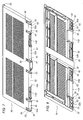
- Figure 1 is a side view, partly in cross section, of a preferred embodiment of the container according to the invention;
- Figure 2 is a side view, partly in cross section, of the preferred embodiment of the container according to the invention in the folded condition;
- Figure 3 is a side view showing only the bottom wall, or base, of the preferred embodiment of the container according to the invention;
- Figure 4 is a perspective view showing only a part of the bottom wall, or base, of the preferred embodiment of the container according to the invention;
- Figure 5 is a side view of a longitudinal wall of the preferred embodiment of the container according to the invention;
- Figure 6 is a cross-section through a hinged area of the end wall of the preferred embodiment of the container according to the invention;
- Figure 7 is a perspective view of the outside of the end wall of the preferred embodiment of the container according to the invention;
- Figure 8 is a perspective view of the inside of the end wall of the preferred embodiment of the container according to the invention;
- Figure 9 is a side view of the slot in the preferred embodiment of the container according to the invention;
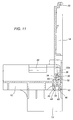
- Figures 10 to 14 illustrate the movement for closing or placing the respective end wall at rest;
- Figure 15 illustrates a detail of the hinged area of the end wall of the preferred embodiment of the container according to the invention.
- A
preferred embodiment 10 of the container according to the invention is described with reference to Figures 1 and 2. - The container, in particular in the form of a box - having components made of moulded plastic - is particularly suitable for transporting fruit and vegetable products and is of the type with collapsible walls, that is to say, walls that can be folded so that the box, when empty, occupies a minimum of space and can be conveniently transported or stored.
- As shown also in Figures 3 to 8, the container, or box, 10 comprises a base, or bottom wall, 12 and a plurality of side walls comprising opposite pairs of walls, referred to herein as first and
second end walls end walls side containment walls - As shown in the drawings, the
base 12 comprises a wall, defining a substantially flat upper surface 12', and a plurality of supporting feet, or, more specifically, threefeet 13 at each longitudinal side of the box, and short longitudinal protrusions in the form ofshort side walls longitudinal walls 18. - As illustrated in particular in Figure 4, the
short coupling walls 112 protrude upwardly from the product supporting surface 12' in the opposite direction to that in which the supportingfeet 13 extend. - The invention contemplates the provision of a first and a second
side end wall - As illustrated, each of the
end walls shaped portion 20 which, as shown in Figure 1, is adapted for coupling to a respective upwardly extendingprotrusion 22 provided on theend longitudinal wall 18. - In practice, when the
longitudinal walls 18 are in the open, or erect, condition, theend walls respective hooking element 20 engages acorresponding portion 22 provided at thecurved end longitudinal wall 18. - Obviously, the hook-
shaped portion 20 and theprotrusion 22 can be disengaged by an upward movement of theend wall longitudinal walls 18. - As shown in particular in Figure 2, in the lowered or collapsed condition, the
end walls base 12, and thelongitudinal walls 18 turned downwards until they lie parallel with the bottom 12' on top of theend walls longitudinal wall 18 comprises at the bottom of it a plurality ofprotrusions 24, defining fork-like elements 26, designed to engagerespective pins 28 atrecesses 30 made in theside walls 112 of thebase 12, thus constituting advantageous means for turning the longitudinal walls about thepins 28. - Means are also advantageously provided for turning the end wall of the container.
- More specifically, the means for turning the side wall of the container are designed to turn the side wall relative to the
bottom wall 12, in particular, from the disengaged, erect position to the rest position or from the rest position to the erect position. - With reference in particular to the
wall 16, as shown in Figures 7 and 8, the means for turning the end wall of the container compriserespective pins 32, distributed along the end wall, and elongated slottedmeans 34, illustrated individually in Figure 9, into which thepin 32 is inserted in freely slidable manner in a vertical direction or according to the long side of theslot 34. - More specifically, as may be inferred from Figures 7 and 8, the
pin 32 extends transversally at a bottom end of themobile wall 16, and in particular, extends from corresponding opposite vertical walls, or faces, labelled 33, defining arespective recess 35 at the bottom of themobile wall 16. - The slotted
means 34 in turn compriserespective tabs bottom wall 12 of the container with which they are associated at holes, labelled 42, open at the top. - As illustrated, these elastically spreading
tabs respective teeth retaining surfaces respective openings 42 made at the edge of the upper surface of thecontainer base 12. - The
slotted body 34 also has protrudingtabs tabs respective slot 34'. - In practice, the moulded plastic components of the container can easily be assembled by snapping the
tabs respective pin 32 in such a way as to insert thepin 32 into the slot opening 34' between the tabs and then inserting thetabs respective opening 42 in such a way as to engage the outward facingteeth retaining surfaces - As illustrated, the
elongated slot 34' extends vertically and is defined at the top by a curved end 34'a from which there extend opposing longitudinal sliding surfaces 34'b, 34'c for thepin 32 and, at the bottom, by theupper surfaces 34'd and 34'e of the aforementionedinner protrusions -
Means mobile walls - As well illustrated also in Figures 7 and 8, these means for guiding the turning movement of the
mobile walls curved surface 52, protruding downwardly from the respectivemobile wall corresponding surface 54, which protrudes upwardly from thebottom wall 12 and which is well illustrated in Figure 4. - In particular, the
curved surface 52 for guiding the turning movement of themobile walls rotation pin 32 and is adapted to define a larger diameter or distance at thepin 32, on the longitudinal extension of thepin 32, and a smaller diameter or width in the direction transversal to thepin 32. - As shown, a section of the outside profile of the cam-
like surface 52 coincides, on the inside, with the outside profile of therespective wall 33, which delimits therecess 35 that houses therotation pin 32, while on the outside, the cam-like surface 52 affords a substantially longitudinal, or vertical,surface 52b that is recessed with respect to the profile of therespective wall 33, in such a way that - when thewall 16 is erect, or vertical - thecam 52 can pass under thesliding protrusion 54, thereby allowing thewall 16 to move from the disengaged, free-turning upper position to the engaged lower position where it is locked to thebottom 12. - Means are advantageously provided for retaining the
respective end walls - These retaining means comprise a
vertical wall 60 extending from theguide protrusion 54 and acting in conjunction with the correspondinglongitudinal surface 52b of the cam-like protrusion 52. - As illustrated, the
coupling pins 28 of thelongitudinal walls 18 are located at a level above the level corresponding to the coupling area of theend walls - Also, with reference to the
wall 16, it may be noticed how each end wall has lower transversal surfaces 116' between corresponding areas for thepin 32 and corresponding areas for therotation surfaces 52, constituting means for abutting against the upper surface 37' ofprotrusions 37 made between thecorresponding slot 34 insertion areas and the corresponding areas occupied by theguide protrusions 54, as well illustrated in Figure 4. - Below is a brief description of how the box according to the invention is used. Starting from the condition shown in Figure 1, in which the side walls are erect, the
end wall 16 can be lifted from the position shown in Figure 10, and likewise theend wall 14, in such a way as to release thecoupling element 22 from the corresponding coupling portion of thelongitudinal walls 18, positioning therotation pin 32 of thewall 16 at the top of theslot 34', as illustrated in Figure 11, and thus, as shown in Figures 12 and 13, enabling thewalls bottom wall 12. - At this point, it is sufficient to also fold the
longitudinal walls 18 downwards until they rest on top of theend walls longitudinal walls 18 can be opened by turning them about therotation pins 28 from the lowered position, parallel to thebottom 12 of the container, to a position in which thewalls 18 are positioned vertically, and thecorresponding end walls coupling element 20 of the respective end wall with thecorresponding coupling portions 22 on thelongitudinal walls 18 of the container. - The container according to the invention may be made in any desired size. In particular, it may have a
rectangular base 12 with the long side 1200 mm long and the short side 800 mm long, or the long side 800 mm long and the short side 600 mm, so that two smaller boxes placed on top of one another will exactly match the size of a larger box. - The boxes are thus very handy to transport.
- In the case of the two sizes indicated, the short collapsible walls of one size are interchangeable with the long collapsible walls of the other size. These walls are 800 mm long in both cases. Thus, the same collapsible end walls can be used to make containers of different sizes.
- It will be understood that the invention described may be useful in many industrial applications and may be modified and adapted in several ways without thereby departing from the scope of the inventive concept. Moreover, all the details of the invention may be substituted by technically equivalent elements.
Claims (38)
- A container (10), in particular a box, of the type with collapsible walls, comprising a bottom wall (12) and a plurality of side walls (14, 16, 18) mounted on the bottom wall (12) and movable between an erect, containment position and a folded, rest position, characterised in that at least one end side wall (14), when in the erect position, can be moved between an engaged containment position and a disengaged position in which it can be moved freely to the folded position.
- The container according to claim 1, characterised in that it comprises a second end wall (16), which, when in the erect position, can be moved between an engaged containment position and a disengaged position in which it can be moved freely to the folded position.
- The container according to claim 2, characterised in that the second mobile wall (16) is located on the side opposite the first mobile wall (14).
- The container according to any of the foregoing claims, characterised in that the engaged position of the respective end wall (14, 16) is a vertically lowered position of the wall in the erect condition.
- The container according to any of the foregoing claims, characterised in that the disengaged position is a vertically raised position of the end wall (14, 16) in the erect condition.
- The container according to any of the foregoing claims or according to the preamble to claim 1, characterised in that it comprises means (32, 34) for turning the side wall (14, 16).
- The container according to claim 6, characterised in that the means (32, 34) for turning the side wall (14, 16) enable said side end wall (14, 16) to be moved to and from the rest position.
- The container according to claim 6 or 7, characterised in that the means (32, 34) for turning the side wall (14, 16) enable said side end wall (14, 16) to be moved to and from the rest position relative to the bottom wall (12).
- The container according to any of the foregoing claims from 6 to 8, characterised in that the means (32, 34) for turning the side wall (14, 16) enable the side end wall (14, 16) to be moved to and from the disengaged position when the end wall (14, 16) is in the erect condition.
- The container according to any of the foregoing claims from 6 to 9, characterised in that the means for turning the end wall (14, 16) comprise at least one pin (32) cooperating with elongated slotted means (34).
- The container according to claim 10, characterised in that the rotation pin (32) extends transversally from the bottom end of the respective end wall (14).
- The container according to claim 10 or 11, characterised in that the elongated slotted means (34) extend from the bottom wall (12).
- The container according to claim 12, characterised in that the elongated slot (34') extends vertically.
- The container according to any of the foregoing claims from 10 to 13, characterised in that the slotted means are defined by a slotted body (34) that can be associated with the bottom wall (12) of the container.
- The container according to any of the foregoing claims from 10 to 14, characterised in that the slotted means comprise respective tabs (38, 40), which can be moved elastically towards and away from each other and which afford respective teeth (44, 46) for engaging corresponding protrusions (48, 50) at a respective opening (42), giving onto the top of the bottom wall (12).
- The container according to any of the foregoing claims from 10 to 15, characterised in that the slotted means have a curved upper end section (34'a) for retaining the pin during the rotation of the mobile wall (14, 16).
- The container according to any of the foregoing claims from 10 to 16, characterised in that the elastic tabs (38, 40) have respective facing protrusions (38a, 40a) designed to hold the corresponding rotation pin (32).
- The container according to claim 17, characterised in that the facing protrusions (38a, 40a) of the elastic tabs (38, 40) define a curved end section (34'd, 34'e) for retaining the corresponding pin (32) for turning the mobile wall (14, 16) when the mobile wall (14, 16) is in the lowered engaged position.
- The container according to any of the foregoing claims from 6 to 18, characterised in that it comprises means (52, 54) for guiding the mobile wall (14, 16) as it turns to and from the rest position.
- The container according to any of the foregoing claims from 6 to 19, characterised in that it comprises means (52, 54) for guiding the mobile wall (14, 16) as it turns to and from the erect disengaged position.
- The container according to any of the foregoing claims from 6 to 20, characterised in that the means (52) for guiding the mobile wall (14, 16) as it turn comprises a curved surface (52a) at the bottom end of the mobile wall (14, 16), said curved surface being slidable against a corresponding surface (54) of the bottom wall (12).
- The container according to claim 21, characterised in that the curved surface (52) for guiding the mobile wall (14, 16) as it turns is eccentric with respect to the rotation pin (32), being smaller in diameter in the direction transversal to the rotation pin (32).
- The container according to any of the foregoing claims or according to the preamble to claim 1, characterised in that it comprises retaining means for holding the end wall (14, 16) in the erect containment position.
- The container according to any of the foregoing claims, characterised in that the retaining means for holding the end wall (14, 16) in the erect containment position comprise a respective vertical surface (60) of the bottom wall (12) cooperating with a corresponding surface (52b) of the bottom end of the respective containment wall (14, 16).
- The container according to any of the foregoing claims or according to the preamble to claim 1, characterised in that, in the folded rest position, the mobile wall rests on the upper face (12') of the bottom wall (12).
- The container according to any of the foregoing claims or according to the preamble to claim 1, characterised in that it comprises opposite longitudinal walls (18) articulated to the bottom wall (12).
- The container according to claim 26, characterised in that the longitudinal wall is hinged to the bottom wall (12) and is mobile between an erect containment position and a lowered rest position.
- The container according to claim 27, characterised in that, in the rest position, the longitudinal wall is on top of the end walls (14, 16).
- The container according to any of the foregoing claims from 18 to 20, characterised in that, in the rest position, the longitudinal wall (18) is parallel to the bottom wall (12) of the container.
- The container according to any of the foregoing claims or according to the preamble to claim 1, characterised in that, in the erect containment position, the respective end wall (14, 16) is coupled to the longitudinal wall (18) of the container.
- The container according to claim 30, characterised in that the end wall (14, 16) has a coupling portion (20) that faces downwards and engages a corresponding upward facing (22) of the longitudinal wall (18).
- The container according to any of the foregoing claims or according to the preamble to claim 1, characterised in that the bottom wall (12) has a first and a second short longitudinal protrusion (112) located opposite each other and defining means for coupling to the longitudinal walls (18).
- The container according to any of the foregoing claims, characterised in that the bottom wall (12) has pins (28) for coupling to a corresponding longitudinal wall (18) of the container.
- The container according to claim 33, characterised in that the pins (28) for coupling the longitudinal wall (18) are located at a level above the level of the means for articulating the end walls (14, 16) to the bottom wall (12).
- The container according to any of the foregoing claims or according to the preamble to claim 1, characterised in that the longitudinal wall (18) has ends (18a, 18b) that protrude towards the inside of the container.
- The container according to any of the foregoing claims, characterised in that the end wall (14, 16) has a lower wall defining means (116') for abutting against an upper surface (37') of the bottom wall (12).
- The container according to any of the foregoing claims, characterised in that the bottom wall (12) has a plurality of supporting feet (13, 13, 13) protruding downwardly from the bottom wall (12).
- The container according to any of the foregoing claims, characterised in that it is made of plastic.
Applications Claiming Priority (1)
| Application Number | Priority Date | Filing Date | Title |
|---|---|---|---|
| IT000212A ITBO20060212A1 (en) | 2006-03-28 | 2006-03-28 | CONCEALABLE WALL-MOUNTED CONTAINER. |
Publications (2)
| Publication Number | Publication Date |
|---|---|
| EP1840038A1 true EP1840038A1 (en) | 2007-10-03 |
| EP1840038B1 EP1840038B1 (en) | 2009-05-06 |
Family
ID=38222153
Family Applications (1)
| Application Number | Title | Priority Date | Filing Date |
|---|---|---|---|
| EP07004099A Active EP1840038B1 (en) | 2006-03-28 | 2007-02-28 | A collapsible container |
Country Status (4)
| Country | Link |
|---|---|
| EP (1) | EP1840038B1 (en) |
| AT (1) | ATE430700T1 (en) |
| DE (1) | DE602007001046D1 (en) |
| IT (1) | ITBO20060212A1 (en) |
Cited By (10)
| Publication number | Priority date | Publication date | Assignee | Title |
|---|---|---|---|---|
| EP2256050A1 (en) * | 2009-05-29 | 2010-12-01 | KTP Kunstostoff Palettentechnik GmbH | Pallet container with side walls and cover |
| EP2256051A1 (en) * | 2009-05-29 | 2010-12-01 | KTP Kunstostoff Palettentechnik GmbH | Pallet container with side walls and cover |
| WO2011071786A3 (en) * | 2009-12-07 | 2011-09-09 | Plasgad Plastic Products Acs Ltd. | Storage crate |
| US20120181271A1 (en) * | 2009-04-15 | 2012-07-19 | Hendrik Dekkers | Container Comprising a Collapsible Sidewall |
| US8640912B2 (en) | 2009-04-15 | 2014-02-04 | Ifco Systems Gmbh | Box with foldable sidewalls and locking mechanisms with overload protection |
| US8651310B2 (en) | 2009-04-15 | 2014-02-18 | Ifco Systems Gmbh | Box having foldable and dismantlable exterior walls |
| US8662333B2 (en) | 2009-04-15 | 2014-03-04 | Ifco Systems Gmbh | Box having foldable sidewalls with a stable sidewall structure |
| EP3275797A1 (en) * | 2016-07-29 | 2018-01-31 | Schoeller Allibert GmbH | Hinge assembly and container with such a hinge assembly |
| EP3259195A4 (en) * | 2015-02-16 | 2018-09-19 | Dolav Plastic Products Cooperative Society Ltd. | Heavy-duty foldable storage bin |
| IT201900018569A1 (en) * | 2019-10-11 | 2021-04-11 | Antonio Luigi Piero Maria Foresti | EASILY SANITIZABLE PLASTIC CONTAINER FOR THE FOOD INDUSTRY |
Citations (5)
| Publication number | Priority date | Publication date | Assignee | Title |
|---|---|---|---|---|
| US4163495A (en) * | 1977-09-21 | 1979-08-07 | Drader Clarence H | Plastic bread carrier having folding end walls |
| DE8536127U1 (en) * | 1985-12-21 | 1986-02-13 | Sgourakis, Constantin, 5600 Wuppertal | Stackable transport container with foldable walls |
| NL1014717C2 (en) * | 2000-03-22 | 2001-09-25 | Beekenkamp Verpakkingen B V | Collapsible crate used for e.g. carrying shopping, has side walls guided by triangular guides in side wall cavities during unfolding |
| US20040069780A1 (en) * | 2002-10-11 | 2004-04-15 | Rehrig Pacific Company | Portable storage device |
| EP1647492A1 (en) * | 2004-10-13 | 2006-04-19 | Bypsa | Foldable crate |
-
2006
- 2006-03-28 IT IT000212A patent/ITBO20060212A1/en unknown
-
2007
- 2007-02-28 EP EP07004099A patent/EP1840038B1/en active Active
- 2007-02-28 DE DE602007001046T patent/DE602007001046D1/en active Active
- 2007-02-28 AT AT07004099T patent/ATE430700T1/en not_active IP Right Cessation
Patent Citations (5)
| Publication number | Priority date | Publication date | Assignee | Title |
|---|---|---|---|---|
| US4163495A (en) * | 1977-09-21 | 1979-08-07 | Drader Clarence H | Plastic bread carrier having folding end walls |
| DE8536127U1 (en) * | 1985-12-21 | 1986-02-13 | Sgourakis, Constantin, 5600 Wuppertal | Stackable transport container with foldable walls |
| NL1014717C2 (en) * | 2000-03-22 | 2001-09-25 | Beekenkamp Verpakkingen B V | Collapsible crate used for e.g. carrying shopping, has side walls guided by triangular guides in side wall cavities during unfolding |
| US20040069780A1 (en) * | 2002-10-11 | 2004-04-15 | Rehrig Pacific Company | Portable storage device |
| EP1647492A1 (en) * | 2004-10-13 | 2006-04-19 | Bypsa | Foldable crate |
Cited By (15)
| Publication number | Priority date | Publication date | Assignee | Title |
|---|---|---|---|---|
| US8640912B2 (en) | 2009-04-15 | 2014-02-04 | Ifco Systems Gmbh | Box with foldable sidewalls and locking mechanisms with overload protection |
| US8651310B2 (en) | 2009-04-15 | 2014-02-18 | Ifco Systems Gmbh | Box having foldable and dismantlable exterior walls |
| US8662333B2 (en) | 2009-04-15 | 2014-03-04 | Ifco Systems Gmbh | Box having foldable sidewalls with a stable sidewall structure |
| US20120181271A1 (en) * | 2009-04-15 | 2012-07-19 | Hendrik Dekkers | Container Comprising a Collapsible Sidewall |
| US8875924B2 (en) | 2009-04-15 | 2014-11-04 | Ifco Systems Gmbh | Box with foldable sidewalls and locking mechanisms with overload protection |
| US8627973B2 (en) * | 2009-04-15 | 2014-01-14 | Ifco Systems Gmbh | Container comprising a collapsible sidewall |
| EP2256051A1 (en) * | 2009-05-29 | 2010-12-01 | KTP Kunstostoff Palettentechnik GmbH | Pallet container with side walls and cover |
| EP2256050A1 (en) * | 2009-05-29 | 2010-12-01 | KTP Kunstostoff Palettentechnik GmbH | Pallet container with side walls and cover |
| GB2488084A (en) * | 2009-12-07 | 2012-08-15 | Plasgad Plastic Products Acs Ltd | Storage crate |
| GB2488084B (en) * | 2009-12-07 | 2014-07-23 | Plasgad Plastic Products Acs Ltd | Storage crate |
| WO2011071786A3 (en) * | 2009-12-07 | 2011-09-09 | Plasgad Plastic Products Acs Ltd. | Storage crate |
| EP3259195A4 (en) * | 2015-02-16 | 2018-09-19 | Dolav Plastic Products Cooperative Society Ltd. | Heavy-duty foldable storage bin |
| EP3275797A1 (en) * | 2016-07-29 | 2018-01-31 | Schoeller Allibert GmbH | Hinge assembly and container with such a hinge assembly |
| US10150587B2 (en) | 2016-07-29 | 2018-12-11 | Schoeller Allibert Gmbh | Hinge assembly and container with such a hinge assembly |
| IT201900018569A1 (en) * | 2019-10-11 | 2021-04-11 | Antonio Luigi Piero Maria Foresti | EASILY SANITIZABLE PLASTIC CONTAINER FOR THE FOOD INDUSTRY |
Also Published As
| Publication number | Publication date |
|---|---|
| ITBO20060212A1 (en) | 2007-09-29 |
| DE602007001046D1 (en) | 2009-06-18 |
| ATE430700T1 (en) | 2009-05-15 |
| EP1840038B1 (en) | 2009-05-06 |
Similar Documents
| Publication | Publication Date | Title |
|---|---|---|
| EP1840038B1 (en) | A collapsible container | |
| CN111406026B (en) | Stackable System Containers and Shipping Systems | |
| EP2164760B1 (en) | Container with a wall which can be lowered | |
| CN104150101B (en) | For providing the device of suction pipe head | |
| CN107249378B (en) | Box (CN) | |
| EP1655232B1 (en) | Folding container | |
| CA2918113C (en) | Collapsible crate | |
| SK279374B6 (en) | PLASTIC CONTAINER, FOLLOW VEGETABLE SHEET | |
| EP2620380A1 (en) | Collapsible container with door | |
| US20160332165A1 (en) | Storage box for a plurality of tubular vessels or other elongate articles | |
| SK283986B6 (en) | Folding container with detachable lockable side walls | |
| EP2091827B1 (en) | Box with collapsible walls designed to stack a corresponding box with lower dimensions | |
| US20240043171A1 (en) | Containers for oil bottles or the like | |
| EP0373547A1 (en) | Shipping container for packing units | |
| DK2726379T3 (en) | PLASTIC CONTAINER WITH FOLDABLE sidewall, AND USE OF A CONTAINER. | |
| MX2011005654A (en) | Dual height collapsible container. | |
| EP2289811B1 (en) | Collapsible crate | |
| US10926915B2 (en) | Collapsible container | |
| ES2946289T3 (en) | plastic container | |
| WO2008012556A2 (en) | A packaging module | |
| NO20190842A1 (en) | A case for storing articles and carrying articles by hand | |
| US9938053B2 (en) | Container having a closable loading opening | |
| KR200449263Y1 (en) | container | |
| KR101658596B1 (en) | box assembly for multi heaping and transporting | |
| KR200445098Y1 (en) | Folding box |
Legal Events
| Date | Code | Title | Description |
|---|---|---|---|
| PUAI | Public reference made under article 153(3) epc to a published international application that has entered the european phase |
Free format text: ORIGINAL CODE: 0009012 |
|
| AK | Designated contracting states |
Kind code of ref document: A1 Designated state(s): AT BE BG CH CY CZ DE DK EE ES FI FR GB GR HU IE IS IT LI LT LU LV MC NL PL PT RO SE SI SK TR |
|
| AX | Request for extension of the european patent |
Extension state: AL BA HR MK YU |
|
| 17P | Request for examination filed |
Effective date: 20080121 |
|
| 17Q | First examination report despatched |
Effective date: 20080214 |
|
| AKX | Designation fees paid |
Designated state(s): AT BE BG CH CY CZ DE DK EE ES FI FR GB GR HU IE IS IT LI LT LU LV MC NL PL PT RO SE SI SK TR |
|
| GRAP | Despatch of communication of intention to grant a patent |
Free format text: ORIGINAL CODE: EPIDOSNIGR1 |
|
| GRAS | Grant fee paid |
Free format text: ORIGINAL CODE: EPIDOSNIGR3 |
|
| GRAA | (expected) grant |
Free format text: ORIGINAL CODE: 0009210 |
|
| AK | Designated contracting states |
Kind code of ref document: B1 Designated state(s): AT BE BG CH CY CZ DE DK EE ES FI FR GB GR HU IE IS IT LI LT LU LV MC NL PL PT RO SE SI SK TR |
|
| REG | Reference to a national code |
Ref country code: GB Ref legal event code: FG4D |
|
| REG | Reference to a national code |
Ref country code: CH Ref legal event code: EP |
|
| REG | Reference to a national code |
Ref country code: IE Ref legal event code: FG4D |
|
| REF | Corresponds to: |
Ref document number: 602007001046 Country of ref document: DE Date of ref document: 20090618 Kind code of ref document: P |
|
| PG25 | Lapsed in a contracting state [announced via postgrant information from national office to epo] |
Ref country code: PT Free format text: LAPSE BECAUSE OF FAILURE TO SUBMIT A TRANSLATION OF THE DESCRIPTION OR TO PAY THE FEE WITHIN THE PRESCRIBED TIME-LIMIT Effective date: 20090906 Ref country code: LT Free format text: LAPSE BECAUSE OF FAILURE TO SUBMIT A TRANSLATION OF THE DESCRIPTION OR TO PAY THE FEE WITHIN THE PRESCRIBED TIME-LIMIT Effective date: 20090506 Ref country code: FI Free format text: LAPSE BECAUSE OF FAILURE TO SUBMIT A TRANSLATION OF THE DESCRIPTION OR TO PAY THE FEE WITHIN THE PRESCRIBED TIME-LIMIT Effective date: 20090506 Ref country code: ES Free format text: LAPSE BECAUSE OF FAILURE TO SUBMIT A TRANSLATION OF THE DESCRIPTION OR TO PAY THE FEE WITHIN THE PRESCRIBED TIME-LIMIT Effective date: 20090817 Ref country code: AT Free format text: LAPSE BECAUSE OF FAILURE TO SUBMIT A TRANSLATION OF THE DESCRIPTION OR TO PAY THE FEE WITHIN THE PRESCRIBED TIME-LIMIT Effective date: 20090506 |
|
| NLV1 | Nl: lapsed or annulled due to failure to fulfill the requirements of art. 29p and 29m of the patents act | ||
| PG25 | Lapsed in a contracting state [announced via postgrant information from national office to epo] |
Ref country code: NL Free format text: LAPSE BECAUSE OF FAILURE TO SUBMIT A TRANSLATION OF THE DESCRIPTION OR TO PAY THE FEE WITHIN THE PRESCRIBED TIME-LIMIT Effective date: 20090506 Ref country code: SI Free format text: LAPSE BECAUSE OF FAILURE TO SUBMIT A TRANSLATION OF THE DESCRIPTION OR TO PAY THE FEE WITHIN THE PRESCRIBED TIME-LIMIT Effective date: 20090506 Ref country code: SE Free format text: LAPSE BECAUSE OF FAILURE TO SUBMIT A TRANSLATION OF THE DESCRIPTION OR TO PAY THE FEE WITHIN THE PRESCRIBED TIME-LIMIT Effective date: 20090806 Ref country code: PL Free format text: LAPSE BECAUSE OF FAILURE TO SUBMIT A TRANSLATION OF THE DESCRIPTION OR TO PAY THE FEE WITHIN THE PRESCRIBED TIME-LIMIT Effective date: 20090506 Ref country code: IS Free format text: LAPSE BECAUSE OF FAILURE TO SUBMIT A TRANSLATION OF THE DESCRIPTION OR TO PAY THE FEE WITHIN THE PRESCRIBED TIME-LIMIT Effective date: 20090906 Ref country code: LV Free format text: LAPSE BECAUSE OF FAILURE TO SUBMIT A TRANSLATION OF THE DESCRIPTION OR TO PAY THE FEE WITHIN THE PRESCRIBED TIME-LIMIT Effective date: 20090506 |
|
| PG25 | Lapsed in a contracting state [announced via postgrant information from national office to epo] |
Ref country code: EE Free format text: LAPSE BECAUSE OF FAILURE TO SUBMIT A TRANSLATION OF THE DESCRIPTION OR TO PAY THE FEE WITHIN THE PRESCRIBED TIME-LIMIT Effective date: 20090506 Ref country code: CZ Free format text: LAPSE BECAUSE OF FAILURE TO SUBMIT A TRANSLATION OF THE DESCRIPTION OR TO PAY THE FEE WITHIN THE PRESCRIBED TIME-LIMIT Effective date: 20090506 Ref country code: RO Free format text: LAPSE BECAUSE OF FAILURE TO SUBMIT A TRANSLATION OF THE DESCRIPTION OR TO PAY THE FEE WITHIN THE PRESCRIBED TIME-LIMIT Effective date: 20090506 Ref country code: DK Free format text: LAPSE BECAUSE OF FAILURE TO SUBMIT A TRANSLATION OF THE DESCRIPTION OR TO PAY THE FEE WITHIN THE PRESCRIBED TIME-LIMIT Effective date: 20090506 |
|
| PG25 | Lapsed in a contracting state [announced via postgrant information from national office to epo] |
Ref country code: SK Free format text: LAPSE BECAUSE OF FAILURE TO SUBMIT A TRANSLATION OF THE DESCRIPTION OR TO PAY THE FEE WITHIN THE PRESCRIBED TIME-LIMIT Effective date: 20090506 Ref country code: BE Free format text: LAPSE BECAUSE OF FAILURE TO SUBMIT A TRANSLATION OF THE DESCRIPTION OR TO PAY THE FEE WITHIN THE PRESCRIBED TIME-LIMIT Effective date: 20090506 |
|
| PLBE | No opposition filed within time limit |
Free format text: ORIGINAL CODE: 0009261 |
|
| STAA | Information on the status of an ep patent application or granted ep patent |
Free format text: STATUS: NO OPPOSITION FILED WITHIN TIME LIMIT |
|
| PG25 | Lapsed in a contracting state [announced via postgrant information from national office to epo] |
Ref country code: BG Free format text: LAPSE BECAUSE OF FAILURE TO SUBMIT A TRANSLATION OF THE DESCRIPTION OR TO PAY THE FEE WITHIN THE PRESCRIBED TIME-LIMIT Effective date: 20090806 |
|
| 26N | No opposition filed |
Effective date: 20100209 |
|
| PG25 | Lapsed in a contracting state [announced via postgrant information from national office to epo] |
Ref country code: GR Free format text: LAPSE BECAUSE OF FAILURE TO SUBMIT A TRANSLATION OF THE DESCRIPTION OR TO PAY THE FEE WITHIN THE PRESCRIBED TIME-LIMIT Effective date: 20090807 Ref country code: MC Free format text: LAPSE BECAUSE OF NON-PAYMENT OF DUE FEES Effective date: 20100301 |
|
| PG25 | Lapsed in a contracting state [announced via postgrant information from national office to epo] |
Ref country code: IE Free format text: LAPSE BECAUSE OF NON-PAYMENT OF DUE FEES Effective date: 20100228 |
|
| PGRI | Patent reinstated in contracting state [announced from national office to epo] |
Ref country code: IT Effective date: 20110501 |
|
| REG | Reference to a national code |
Ref country code: CH Ref legal event code: PL |
|
| PG25 | Lapsed in a contracting state [announced via postgrant information from national office to epo] |
Ref country code: CH Free format text: LAPSE BECAUSE OF NON-PAYMENT OF DUE FEES Effective date: 20110228 Ref country code: LI Free format text: LAPSE BECAUSE OF NON-PAYMENT OF DUE FEES Effective date: 20110228 |
|
| PG25 | Lapsed in a contracting state [announced via postgrant information from national office to epo] |
Ref country code: CY Free format text: LAPSE BECAUSE OF FAILURE TO SUBMIT A TRANSLATION OF THE DESCRIPTION OR TO PAY THE FEE WITHIN THE PRESCRIBED TIME-LIMIT Effective date: 20090506 |
|
| PG25 | Lapsed in a contracting state [announced via postgrant information from national office to epo] |
Ref country code: HU Free format text: LAPSE BECAUSE OF FAILURE TO SUBMIT A TRANSLATION OF THE DESCRIPTION OR TO PAY THE FEE WITHIN THE PRESCRIBED TIME-LIMIT Effective date: 20091107 Ref country code: LU Free format text: LAPSE BECAUSE OF NON-PAYMENT OF DUE FEES Effective date: 20100228 |
|
| PG25 | Lapsed in a contracting state [announced via postgrant information from national office to epo] |
Ref country code: TR Free format text: LAPSE BECAUSE OF FAILURE TO SUBMIT A TRANSLATION OF THE DESCRIPTION OR TO PAY THE FEE WITHIN THE PRESCRIBED TIME-LIMIT Effective date: 20090506 |
|
| REG | Reference to a national code |
Ref country code: FR Ref legal event code: PLFP Year of fee payment: 10 |
|
| REG | Reference to a national code |
Ref country code: FR Ref legal event code: PLFP Year of fee payment: 11 |
|
| REG | Reference to a national code |
Ref country code: FR Ref legal event code: PLFP Year of fee payment: 12 |
|
| P01 | Opt-out of the competence of the unified patent court (upc) registered |
Effective date: 20230505 |
|
| PGFP | Annual fee paid to national office [announced via postgrant information from national office to epo] |
Ref country code: GB Payment date: 20260223 Year of fee payment: 20 |
|
| PGFP | Annual fee paid to national office [announced via postgrant information from national office to epo] |
Ref country code: DE Payment date: 20260220 Year of fee payment: 20 |
|
| PGFP | Annual fee paid to national office [announced via postgrant information from national office to epo] |
Ref country code: IT Payment date: 20260223 Year of fee payment: 20 |
|
| PGFP | Annual fee paid to national office [announced via postgrant information from national office to epo] |
Ref country code: FR Payment date: 20260227 Year of fee payment: 20 |