EP1839886B1 - Sheet feeding apparatus and image forming apparatus - Google Patents
Sheet feeding apparatus and image forming apparatus Download PDFInfo
- Publication number
- EP1839886B1 EP1839886B1 EP07104503A EP07104503A EP1839886B1 EP 1839886 B1 EP1839886 B1 EP 1839886B1 EP 07104503 A EP07104503 A EP 07104503A EP 07104503 A EP07104503 A EP 07104503A EP 1839886 B1 EP1839886 B1 EP 1839886B1
- Authority
- EP
- European Patent Office
- Prior art keywords
- sheet
- sensor
- sheets
- sheet feeding
- tray
- Prior art date
- Legal status (The legal status is an assumption and is not a legal conclusion. Google has not performed a legal analysis and makes no representation as to the accuracy of the status listed.)
- Expired - Fee Related
Links
Images


Classifications
-
- B—PERFORMING OPERATIONS; TRANSPORTING
- B41—PRINTING; LINING MACHINES; TYPEWRITERS; STAMPS
- B41J—TYPEWRITERS; SELECTIVE PRINTING MECHANISMS, i.e. MECHANISMS PRINTING OTHERWISE THAN FROM A FORME; CORRECTION OF TYPOGRAPHICAL ERRORS
- B41J11/00—Devices or arrangements of selective printing mechanisms, e.g. ink-jet printers or thermal printers, for supporting or handling copy material in sheet or web form
- B41J11/009—Detecting type of paper, e.g. by automatic reading of a code that is printed on a paper package or on a paper roll or by sensing the grade of translucency of the paper
-
- B—PERFORMING OPERATIONS; TRANSPORTING
- B41—PRINTING; LINING MACHINES; TYPEWRITERS; STAMPS
- B41J—TYPEWRITERS; SELECTIVE PRINTING MECHANISMS, i.e. MECHANISMS PRINTING OTHERWISE THAN FROM A FORME; CORRECTION OF TYPOGRAPHICAL ERRORS
- B41J11/00—Devices or arrangements of selective printing mechanisms, e.g. ink-jet printers or thermal printers, for supporting or handling copy material in sheet or web form
- B41J11/0045—Guides for printing material
- B41J11/0055—Lateral guides, e.g. guides for preventing skewed conveyance of printing material
-
- B—PERFORMING OPERATIONS; TRANSPORTING
- B41—PRINTING; LINING MACHINES; TYPEWRITERS; STAMPS
- B41J—TYPEWRITERS; SELECTIVE PRINTING MECHANISMS, i.e. MECHANISMS PRINTING OTHERWISE THAN FROM A FORME; CORRECTION OF TYPOGRAPHICAL ERRORS
- B41J11/00—Devices or arrangements of selective printing mechanisms, e.g. ink-jet printers or thermal printers, for supporting or handling copy material in sheet or web form
- B41J11/0025—Handling copy materials differing in width
-
- B—PERFORMING OPERATIONS; TRANSPORTING
- B41—PRINTING; LINING MACHINES; TYPEWRITERS; STAMPS
- B41J—TYPEWRITERS; SELECTIVE PRINTING MECHANISMS, i.e. MECHANISMS PRINTING OTHERWISE THAN FROM A FORME; CORRECTION OF TYPOGRAPHICAL ERRORS
- B41J13/00—Devices or arrangements of selective printing mechanisms, e.g. ink-jet printers or thermal printers, specially adapted for supporting or handling copy material in short lengths, e.g. sheets
- B41J13/0009—Devices or arrangements of selective printing mechanisms, e.g. ink-jet printers or thermal printers, specially adapted for supporting or handling copy material in short lengths, e.g. sheets control of the transport of the copy material
- B41J13/0018—Devices or arrangements of selective printing mechanisms, e.g. ink-jet printers or thermal printers, specially adapted for supporting or handling copy material in short lengths, e.g. sheets control of the transport of the copy material in the sheet input section of automatic paper handling systems
-
- B—PERFORMING OPERATIONS; TRANSPORTING
- B41—PRINTING; LINING MACHINES; TYPEWRITERS; STAMPS
- B41J—TYPEWRITERS; SELECTIVE PRINTING MECHANISMS, i.e. MECHANISMS PRINTING OTHERWISE THAN FROM A FORME; CORRECTION OF TYPOGRAPHICAL ERRORS
- B41J13/00—Devices or arrangements of selective printing mechanisms, e.g. ink-jet printers or thermal printers, specially adapted for supporting or handling copy material in short lengths, e.g. sheets
- B41J13/10—Sheet holders, retainers, movable guides, or stationary guides
- B41J13/103—Sheet holders, retainers, movable guides, or stationary guides for the sheet feeding section
-
- B—PERFORMING OPERATIONS; TRANSPORTING
- B41—PRINTING; LINING MACHINES; TYPEWRITERS; STAMPS
- B41J—TYPEWRITERS; SELECTIVE PRINTING MECHANISMS, i.e. MECHANISMS PRINTING OTHERWISE THAN FROM A FORME; CORRECTION OF TYPOGRAPHICAL ERRORS
- B41J13/00—Devices or arrangements of selective printing mechanisms, e.g. ink-jet printers or thermal printers, specially adapted for supporting or handling copy material in short lengths, e.g. sheets
- B41J13/26—Registering devices
- B41J13/30—Side lays or gauges
-
- B—PERFORMING OPERATIONS; TRANSPORTING
- B65—CONVEYING; PACKING; STORING; HANDLING THIN OR FILAMENTARY MATERIAL
- B65H—HANDLING THIN OR FILAMENTARY MATERIAL, e.g. SHEETS, WEBS, CABLES
- B65H3/00—Separating articles from piles
- B65H3/02—Separating articles from piles using friction forces between articles and separator
- B65H3/06—Rollers or like rotary separators
-
- B—PERFORMING OPERATIONS; TRANSPORTING
- B65—CONVEYING; PACKING; STORING; HANDLING THIN OR FILAMENTARY MATERIAL
- B65H—HANDLING THIN OR FILAMENTARY MATERIAL, e.g. SHEETS, WEBS, CABLES
- B65H7/00—Controlling article feeding, separating, pile-advancing, or associated apparatus, to take account of incorrect feeding, absence of articles, or presence of faulty articles
- B65H7/02—Controlling article feeding, separating, pile-advancing, or associated apparatus, to take account of incorrect feeding, absence of articles, or presence of faulty articles by feelers or detectors
- B65H7/14—Controlling article feeding, separating, pile-advancing, or associated apparatus, to take account of incorrect feeding, absence of articles, or presence of faulty articles by feelers or detectors by photoelectric feelers or detectors
-
- G—PHYSICS
- G03—PHOTOGRAPHY; CINEMATOGRAPHY; ANALOGOUS TECHNIQUES USING WAVES OTHER THAN OPTICAL WAVES; ELECTROGRAPHY; HOLOGRAPHY
- G03G—ELECTROGRAPHY; ELECTROPHOTOGRAPHY; MAGNETOGRAPHY
- G03G15/00—Apparatus for electrographic processes using a charge pattern
- G03G15/65—Apparatus which relate to the handling of copy material
- G03G15/6502—Supplying of sheet copy material; Cassettes therefor
-
- B—PERFORMING OPERATIONS; TRANSPORTING
- B65—CONVEYING; PACKING; STORING; HANDLING THIN OR FILAMENTARY MATERIAL
- B65H—HANDLING THIN OR FILAMENTARY MATERIAL, e.g. SHEETS, WEBS, CABLES
- B65H2511/00—Dimensions; Position; Numbers; Identification; Occurrences
- B65H2511/40—Identification
- B65H2511/416—Identification of material
-
- B—PERFORMING OPERATIONS; TRANSPORTING
- B65—CONVEYING; PACKING; STORING; HANDLING THIN OR FILAMENTARY MATERIAL
- B65H—HANDLING THIN OR FILAMENTARY MATERIAL, e.g. SHEETS, WEBS, CABLES
- B65H2515/00—Physical entities not provided for in groups B65H2511/00 or B65H2513/00
- B65H2515/60—Optical characteristics, e.g. colour, light
-
- B—PERFORMING OPERATIONS; TRANSPORTING
- B65—CONVEYING; PACKING; STORING; HANDLING THIN OR FILAMENTARY MATERIAL
- B65H—HANDLING THIN OR FILAMENTARY MATERIAL, e.g. SHEETS, WEBS, CABLES
- B65H2553/00—Sensing or detecting means
- B65H2553/40—Sensing or detecting means using optical, e.g. photographic, elements
- B65H2553/41—Photoelectric detectors
- B65H2553/412—Photoelectric detectors in barrier arrangements, i.e. emitter facing a receptor element
-
- B—PERFORMING OPERATIONS; TRANSPORTING
- B65—CONVEYING; PACKING; STORING; HANDLING THIN OR FILAMENTARY MATERIAL
- B65H—HANDLING THIN OR FILAMENTARY MATERIAL, e.g. SHEETS, WEBS, CABLES
- B65H2557/00—Means for control not provided for in groups B65H2551/00 - B65H2555/00
- B65H2557/60—Details of processes or procedures
- B65H2557/64—Details of processes or procedures for detecting type or properties of handled material
-
- G—PHYSICS
- G03—PHOTOGRAPHY; CINEMATOGRAPHY; ANALOGOUS TECHNIQUES USING WAVES OTHER THAN OPTICAL WAVES; ELECTROGRAPHY; HOLOGRAPHY
- G03G—ELECTROGRAPHY; ELECTROPHOTOGRAPHY; MAGNETOGRAPHY
- G03G2215/00—Apparatus for electrophotographic processes
- G03G2215/00362—Apparatus for electrophotographic processes relating to the copy medium handling
- G03G2215/00535—Stable handling of copy medium
- G03G2215/00556—Control of copy medium feeding
- G03G2215/00586—Control of copy medium feeding duplex mode
Definitions
- the present invention relates to a sheet feeding apparatus for separating and feeding stacked sheets one by one and to an image forming apparatus such as copying apparatus or printer using the sheet feeding apparatus.
- An image forming apparatus such as copying apparatus or printer separates and feeds stacked sheets one by one and forms an image.
- the operation is limited depending on a type of sheet which is fed. For example, in the case of a transparent sheet such as an OHP sheet, duplex printing cannot be performed. If the user erroneously selected the duplex printing, generally, the image forming apparatus stops the operation or controls so as to automatically perform simplex printing.
- a method of detecting the sheet type for example, there is a method whereby a reflecting type sensor is used, the sheet type is detected by reflectance of the sheet, and the image forming apparatus is controlled based on a detection result (refer to Japanese Patent Application Laid-Open No. 2000-098813 ).
- Japanese Patent Application Laid-Open No. 2002-139963 A construction in which a reflecting type sensor is attached to a side regulating plate and a type of stacked sheet bundle is detected by the sensor has been disclosed in Japanese Patent Application Laid-Open No. 2002-139963 .
- the sensor disclosed in Japanese Patent Application Laid-Open No. 2002-139963 is a reflecting type optical sensor having a light emitting element (not shown) for emitting light and a photosensing device (not shown) for receiving reflection light of the light emitted from the light emitting element. The reflection light from a top one of the papers stacked on a feeding tray is received by the photosensing device. The type of the paper is discriminated based on an output of the received light.
- Document JP 07 196 207 A discloses an apparatus according to the preamble of claim 1, and a method for discriminating the kind of paper.
- a printing paper sheet is drawn out by a predetermined distance from a paper feeding tray before printing is started and then the printing paper is stopped.
- a quantity of transmitted light passing through the printing paper sheet is detected by a projector and a light receiving device forming an optical axis which crosses the printing paper drawn out from the paper feeding tray, and the light quantity is converted into a voltage corresponding to the light quantity.
- This voltage is compared with a predetermined threshold voltage, and the kind of the printing paper is discriminated on the basis of the comparison result. Further, the discrimination result is fed back to the host computer.
- the invention is made in consideration of the above problems and it is an object of the invention to provide a sheet feeding apparatus which can certainly detect a sheet type and an image forming apparatus using the sheet feeding apparatus.
- the above object is solved by a sheet feeding apparatus having the features of claim 1.
- the above object is solved by an image forming apparatus having the features of claim 4. Further developments are stated in the dependent claims.
- FIG. 1 is a cross sectional explanatory diagram illustrating a whole image forming apparatus.
- FIG. 2 is a perspective explanatory diagram of a sheet feeding apparatus.
- FIG. 3 is a perspective explanatory diagram of the sheet feeding apparatus in the case where a side regulating member has been moved.
- FIG. 4 is a cross sectional explanatory diagram of the sheet feeding apparatus.
- FIG. 5 is a constructional explanatory diagram of a sheet detecting sensor.
- FIG. 6 is a constructional explanatory diagram of the sheet detecting sensor.
- FIG. 7 is a constructional explanatory diagram of the sheet detecting sensor having a dust proofing member.
- FIG. 8 is a constructional explanatory diagram of the sheet detecting sensor having the dust proofing member.
- a sheet feeding apparatus A of a cassette type and a sheet feeding apparatus B of a manual inserting type are arranged in a lower portion of the apparatus main body.
- an image forming portion C an image is formed onto a sheet which is fed from one of the sheet feeding apparatuses.
- the image forming portion of the embodiment uses an electrophotographic system. That is, a latent image is formed by selectively exposing onto a rotating photosensitive drum 100 from an optical scanner 101. The latent image is developed with toner by a developing unit 102 and visualized. The toner image is transferred onto the fed sheet, thereby recording the image. Further, the sheet is conveyed to a fixing unit 103 and the toner image is fixed with a heat. Thereafter, the sheet is discharged to a discharge portion 105 by a discharge roller pair 104.
- An original reading apparatus 106 is arranged over the apparatus main body.
- the original reading apparatus 106 optically reads information of an original document and converts the information into a digital signal.
- the optical scanner 101 selectively exposes based on the digital signal.
- the sheet feeding apparatus A of the cassette type sheets S have been stacked on a sheet cassette 200 which is detachable for the apparatus main body, and the sheets S are fed to a separating portion by a pickup roller 201.
- the separating portion is constructed by: a feed roller 202 which rotates in such a direction as to feed the sheet; and a retard roller 203 which rotates in such a direction as to return the sheet.
- the sheets are separated and fed one by one.
- a tray 1 as a sheet setting portion is rotatably provided for the apparatus main body.
- the tray 1 is opened as illustrated in FIG. 1 and the sheets S are stacked thereon.
- the sheets are fed to the image forming portion C by a feed roller 2.
- the feed roller 2 faces a separating pad 3.
- the fed sheets S are separated one by one by a frictional force of the separating pad 3 and fed by the feed roller 2.
- a sheet feeding portion is constructed by the feed roller 2 and the separating pad 3.
- a sheet detecting sensor 5 to detect a type of sheet which is fed is provided for the sheet feeding apparatus B of the manual inserting type of the embodiment. A detecting construction of the sheet type will now be described.
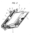
- FIG. 2 is a perspective explanatory diagram of the manual inserting sheet feeding apparatus.
- a bundle of sheets S are stacked onto the tray 1.
- Side regulating members 4a and 4b are in contact with both side edge portions in the width direction (direction which perpendicularly crosses a sheet feeding direction) of the sheet S.
- the side regulating members 4a and 4b guide the fed sheet so that it does not move obliquely and are movable in the sheet width direction according to a sheet width.
- the sheet detecting sensor 5 to detect the sheet type is provided for one of the side regulating members (in this case, 4a) between the side regulating members 4a and 4b.
- An extending portion 70 which extends to a downstream side of the sheet feeding portion is formed to the side regulating member 4a.
- the sheet detecting sensor 5 is provided for the extending portion 70.
- the sheet detecting sensor 5 in the embodiment is arranged on the sheet feeding direction downstream side of the contact portion between the feed roller 2 and the separating pad.
- the sheet detecting sensor 5 is a transmissive photosensor arranged in such a manner that a light emitting portion 5a for emitting light and a photosensing portion 5b for receiving the light emitted from the light emitting portion 5a face in the vertical direction.
- the sheet detecting sensor 5 discriminates the type of the sheet protruded. At this time, the other part of the protruded sheet is still on the tray 1.
- the feed roller 2 protrudes a part of one sheet of sheets stacked on the tray 1 from the tray 1.
- the sheet detecting sensor 5 in the embodiment detects whether or not the sheet type indicates the OHP sheet by the light transmittance. Further, the sheet detecting sensor 5 in the embodiment detects whether the sheet is thick paper or thin paper by the light transmittance.
- FIG. 3 is an explanatory diagram of the sheet feeding apparatus in which the sheets S whose size is smaller than that in the case of FIG. 2 have been stacked.
- the sheet detecting sensor 5 attached to the extending portion 70 of the side regulating member 4a moves integratedly with the movement of the side regulating member 4a. Therefore, irrespective of the sheet size, an edge portion of the sheet which is fed passes through the sheet detecting sensor 5 and the sheet type can be certainly detected.
- the sheet detecting sensor is a sensor in which the light emitting portion 5a and the photosensing portion 5b are integrated.
- the sheet detecting sensor 5 has a coupling portion 5c (refer to FIG. 5 ) which couples the light emitting portion 5a and the photosensing portion 5b.
- the sheet type can be detected by the edge portion of the sheet. Therefore, the sheet detecting sensor 5 can be attached to the side regulating member 4a.
- a vibration is applied to the sheet detecting sensor 5 in association with the movement of the side regulating member 4a.
- the transmissive photosensor is used as a sheet detecting sensor 5, for example, an influence of an output fluctuation that is caused due to the fluttering of the sheet is smaller than that of the reflecting type sensor and the erroneous detection of the sheet type can be prevented.
- the sheet detecting sensor 5 is arranged on the downstream side in the sheet feeding direction of the sheet feeding portion, when the sheet type is detected, the separating operation has been finished and the fluttering of the sheet has already been settled. Therefore, a stable output can be obtained in the sheet detecting portion and the erroneous detection can be prevented. With respect to each of the sheets which have been separated and fed one by one by the sheet feeding portion, the sheet detecting sensor 5 detects the sheet type. Thus, even if the sheets S are set onto the tray 1 in the state where different types of sheets are mixed, the sheet type is hardly erroneously detected.
- guiding portions 6 for guiding the sheet which is fed are formed in the extending portion 70 on the upstream and downstream sides in the sheet feeding direction of the sheet detecting sensor 5.
- the guiding portions 6 guide the edge portions of the sheet fed by the feed roller 2 to a position between the light emitting portion 5a and the photosensing portion 5b.
- the guiding portions 6 also guide the sheet which passed through the sheet detecting sensor (between the light emitting portion 5a and the photosensing portion 5b) 5 to the image forming portion.
- the light emitting portion 5a and the photosensing portion 5b formed as a sheet detecting sensor 5 unit construct a part of the guiding portion which guides the sheet which is fed.
- the motion of the sheet which passes through the sheet detecting sensor 5 is stabilized and the detecting precision of the sheet type is also stabilized.
- the sheet detecting sensor 5 as a part of the sheet guides, the light emitting portion 5a and the photosensing portion 5b can be made to further approach the sheet.
- the sheet type can be detected at higher precision.
- the sheet type by detecting the sheet type at the edge portions in the sheet width direction, the sheet type can be detected by the sensor in which the photosensing portion and the light emitting portion are integrated. Further, even in the case where since the side regulating members move, the vibration is applied to the sheet detecting sensor and the sensor surfaces are covered with the foreign substance, the foreign substance is dropped by the vibration. Therefore, there is also such an effect that a troublesomeness such as cleaning or the like is reduced.
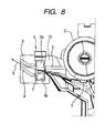
- a dust proofing member for preventing a foreign substance such as paper powder or the like from being deposited onto the sensor surfaces of the sheet detecting sensor 5 may be provided.
- a sheet member 7 is provided so as to cover the upper surface of the photosensing portion 5b whose sensor surface faces upward between the light emitting portion 5a and the photosensing portion 5b.
- the sheet member 7 is made of a transparent flexible sheet. One edge portion of the sheet member 7 is adhered to the edge portion of the tray 1 and the other edge side is extended between the light emitting portion 5a and the photosensing portion 5b.
- a transparent polyester sheet having a thickness of about 0.3mm is used as a sheet member 7.
- the sheet member 7 is pressed and bent by the sheet S and the sensor surface of the photosensing portion 5b is covered with the sheet member 7. Therefore, the paper powder or the like deposited to the sheet S is not dropped and adhered onto the sensor surface of the photosensing portion 5b and the erroneous detection of the sheet type can be prevented. Even if the paper powder or the like has been adhered onto the sheet member 7, when the sheet member 7 is pressed and bent by the sheet which is fed, the paper powder or the like is dropped out from the sheet member 7. Since the sheet member 7 is provided so as to cover the sensor surface of the photosensing portion 5b, the paper powder or the like dropped out from the sheet S is not dropped onto the sensor surface of the photosensing portion 5b.
- the type of sheet S which is fed to the image forming portion is discriminated as mentioned above.
- the image is formed by the image forming portion based on a discrimination result. For example, if the fed sheet is an OHP sheet, even if the user selected the duplex recording, the recording mode is changed to the simplex recording and the image is recorded without executing the duplex recording. Thus, a wasteful execution of an image forming process can be prevented.
Description
- The present invention relates to a sheet feeding apparatus for separating and feeding stacked sheets one by one and to an image forming apparatus such as copying apparatus or printer using the sheet feeding apparatus.
- An image forming apparatus such as copying apparatus or printer separates and feeds stacked sheets one by one and forms an image. However, in such an image forming apparatus, the operation is limited depending on a type of sheet which is fed. For example, in the case of a transparent sheet such as an OHP sheet, duplex printing cannot be performed. If the user erroneously selected the duplex printing, generally, the image forming apparatus stops the operation or controls so as to automatically perform simplex printing.
- For this purpose, it is necessary to detect the sheet type. As a method of detecting the sheet type, for example, there is a method whereby a reflecting type sensor is used, the sheet type is detected by reflectance of the sheet, and the image forming apparatus is controlled based on a detection result (refer to Japanese Patent Application Laid-Open No.
2000-098813 - However, in the case of a construction using the reflecting type sensor as disclosed in Japanese Patent Application Laid-Open No.
2000-098813 - Further, there occurs a case where a foreign substance or the like is deposited onto the sensor surface due to the passage of the sheet and an accurate output is derived.
- A construction in which a reflecting type sensor is attached to a side regulating plate and a type of stacked sheet bundle is detected by the sensor has been disclosed in Japanese Patent Application Laid-Open No.
2002-139963 2002-139963 - In the construction disclosed in Japanese Patent Application Laid-Open No.
2002-139963 - Document
JP 07 196 207 A - The invention is made in consideration of the above problems and it is an object of the invention to provide a sheet feeding apparatus which can certainly detect a sheet type and an image forming apparatus using the sheet feeding apparatus.
- With respect to the sheet feeding apparatus, the above object is solved by a sheet feeding apparatus having the features of claim 1. With respect to the image forming apparatus, the above object is solved by an image forming apparatus having the features of claim 4. Further developments are stated in the dependent claims.
- Further features of the present invention will become apparent from the following description of exemplary embodiments with reference to the attached drawings.
-
FIG. 1 is a cross sectional explanatory diagram illustrating a whole image forming apparatus. -
FIG. 2 is a perspective explanatory diagram of a sheet feeding apparatus. -
FIG. 3 is a perspective explanatory diagram of the sheet feeding apparatus in the case where a side regulating member has been moved. -
FIG. 4 is a cross sectional explanatory diagram of the sheet feeding apparatus. -
FIG. 5 is a constructional explanatory diagram of a sheet detecting sensor. -
FIG. 6 is a constructional explanatory diagram of the sheet detecting sensor. -
FIG. 7 is a constructional explanatory diagram of the sheet detecting sensor having a dust proofing member. -
FIG. 8 is a constructional explanatory diagram of the sheet detecting sensor having the dust proofing member. - An image forming apparatus using a sheet feeding apparatus according to an embodiment of the invention will now be described with reference to the drawings.
- {Whole construction of image forming apparatus}
- First, a whole construction of the image forming apparatus will be briefly described with reference to
FIG. 1 . A sheet feeding apparatus A of a cassette type and a sheet feeding apparatus B of a manual inserting type are arranged in a lower portion of the apparatus main body. In an image forming portion C, an image is formed onto a sheet which is fed from one of the sheet feeding apparatuses. The image forming portion of the embodiment uses an electrophotographic system. That is, a latent image is formed by selectively exposing onto a rotatingphotosensitive drum 100 from anoptical scanner 101. The latent image is developed with toner by a developingunit 102 and visualized. The toner image is transferred onto the fed sheet, thereby recording the image. Further, the sheet is conveyed to afixing unit 103 and the toner image is fixed with a heat. Thereafter, the sheet is discharged to adischarge portion 105 by adischarge roller pair 104. - An
original reading apparatus 106 is arranged over the apparatus main body. Theoriginal reading apparatus 106 optically reads information of an original document and converts the information into a digital signal. Theoptical scanner 101 selectively exposes based on the digital signal. - {Sheet feeding apparatus}
- As illustrated in
FIG. 1 , according to the sheet feeding apparatus A of the cassette type, sheets S have been stacked on asheet cassette 200 which is detachable for the apparatus main body, and the sheets S are fed to a separating portion by apickup roller 201. The separating portion is constructed by: afeed roller 202 which rotates in such a direction as to feed the sheet; and aretard roller 203 which rotates in such a direction as to return the sheet. Thus, the sheets are separated and fed one by one. - According to the sheet feeding apparatus B of the manual inserting type, a tray 1 as a sheet setting portion is rotatably provided for the apparatus main body. The tray 1 is opened as illustrated in
FIG. 1 and the sheets S are stacked thereon. The sheets are fed to the image forming portion C by afeed roller 2. Thefeed roller 2 faces a separatingpad 3. The fed sheets S are separated one by one by a frictional force of the separatingpad 3 and fed by thefeed roller 2. In the embodiment, a sheet feeding portion is constructed by thefeed roller 2 and theseparating pad 3. - (Sheet detecting construction)
- A
sheet detecting sensor 5 to detect a type of sheet which is fed is provided for the sheet feeding apparatus B of the manual inserting type of the embodiment. A detecting construction of the sheet type will now be described. -
FIG. 2 is a perspective explanatory diagram of the manual inserting sheet feeding apparatus. A bundle of sheets S are stacked onto the tray 1.Side regulating members side regulating members - The
sheet detecting sensor 5 to detect the sheet type is provided for one of the side regulating members (in this case, 4a) between theside regulating members portion 70 which extends to a downstream side of the sheet feeding portion is formed to theside regulating member 4a. Thesheet detecting sensor 5 is provided for the extendingportion 70. Thesheet detecting sensor 5 in the embodiment is arranged on the sheet feeding direction downstream side of the contact portion between thefeed roller 2 and the separating pad. Thesheet detecting sensor 5 is a transmissive photosensor arranged in such a manner that alight emitting portion 5a for emitting light and aphotosensing portion 5b for receiving the light emitted from thelight emitting portion 5a face in the vertical direction. - In the state in which a part of one sheet of the sheets stacked on the tray 1 is protruded from the tray 1 by the
feed roller 2, thesheet detecting sensor 5 discriminates the type of the sheet protruded. At this time, the other part of the protruded sheet is still on the tray 1. Thefeed roller 2 protrudes a part of one sheet of sheets stacked on the tray 1 from the tray 1. When the protruded part of the sheet passes between thelight emitting portion 5a and thephotosensing portion 5b, if the sheet is an OHP sheet, the light transmits and if the sheet is an opaque sheet, the light is shut off. Among the light transmitting sheets, there are a sheet such as an OHP sheet whose light transmittance is equal to, for example, about 80% and through which the light can easily transmit and a sheet such as tracing paper whose light transmittance is equal to a low value within a range, for example, from 30 to 50 %. Therefore, by detecting a difference between the amounts of light which passed through the sheets and received by thephotosensing portion 5b, the sheet type can be discriminated. When showing a specific example as a reference, in the case of general paper, a light transmittance is equal to about 10% and in the case of thick paper, a light transmittance is equal to about 2 to 3 %. That is, thesheet detecting sensor 5 in the embodiment detects whether or not the sheet type indicates the OHP sheet by the light transmittance. Further, thesheet detecting sensor 5 in the embodiment detects whether the sheet is thick paper or thin paper by the light transmittance. -
FIG. 3 is an explanatory diagram of the sheet feeding apparatus in which the sheets S whose size is smaller than that in the case ofFIG. 2 have been stacked. Thesheet detecting sensor 5 attached to the extendingportion 70 of theside regulating member 4a moves integratedly with the movement of theside regulating member 4a. Therefore, irrespective of the sheet size, an edge portion of the sheet which is fed passes through thesheet detecting sensor 5 and the sheet type can be certainly detected. - The sheet detecting sensor is a sensor in which the
light emitting portion 5a and thephotosensing portion 5b are integrated. Thesheet detecting sensor 5 has acoupling portion 5c (refer toFIG. 5 ) which couples thelight emitting portion 5a and thephotosensing portion 5b. By using the transmissive photosensor in which thelight emitting portion 5a and thephotosensing portion 5b are integrated, the sheet type can be detected by the edge portion of the sheet. Therefore, thesheet detecting sensor 5 can be attached to theside regulating member 4a. Each time the sheet size is changed, a vibration is applied to thesheet detecting sensor 5 in association with the movement of theside regulating member 4a. Therefore, even if a foreign substance such as paper powder or the like was adhered onto the sensor surfaces (the surface onto which thelight emitting portion 5a emits the light and the surface on which thephotosensing portion 5b receives the light), since the foreign substance is dropped out by the vibration, a troublesomeness such as cleaning or the like is also reduced. - Since the transmissive photosensor is used as a
sheet detecting sensor 5, for example, an influence of an output fluctuation that is caused due to the fluttering of the sheet is smaller than that of the reflecting type sensor and the erroneous detection of the sheet type can be prevented. - Further, since the
sheet detecting sensor 5 is arranged on the downstream side in the sheet feeding direction of the sheet feeding portion, when the sheet type is detected, the separating operation has been finished and the fluttering of the sheet has already been settled. Therefore, a stable output can be obtained in the sheet detecting portion and the erroneous detection can be prevented. With respect to each of the sheets which have been separated and fed one by one by the sheet feeding portion, thesheet detecting sensor 5 detects the sheet type. Thus, even if the sheets S are set onto the tray 1 in the state where different types of sheets are mixed, the sheet type is hardly erroneously detected. - As illustrated in
FIGs. 4 to 6 , guidingportions 6 for guiding the sheet which is fed are formed in the extendingportion 70 on the upstream and downstream sides in the sheet feeding direction of thesheet detecting sensor 5. The guidingportions 6 guide the edge portions of the sheet fed by thefeed roller 2 to a position between thelight emitting portion 5a and thephotosensing portion 5b. The guidingportions 6 also guide the sheet which passed through the sheet detecting sensor (between thelight emitting portion 5a and thephotosensing portion 5b) 5 to the image forming portion. Thelight emitting portion 5a and thephotosensing portion 5b formed as asheet detecting sensor 5 unit construct a part of the guiding portion which guides the sheet which is fed. - Consequently, as illustrated in
FIG. 6 , the motion of the sheet which passes through thesheet detecting sensor 5 is stabilized and the detecting precision of the sheet type is also stabilized. By constructing thesheet detecting sensor 5 as a part of the sheet guides, thelight emitting portion 5a and thephotosensing portion 5b can be made to further approach the sheet. The sheet type can be detected at higher precision. - In the construction of the embodiment, by detecting the sheet type at the edge portions in the sheet width direction, the sheet type can be detected by the sensor in which the photosensing portion and the light emitting portion are integrated. Further, even in the case where since the side regulating members move, the vibration is applied to the sheet detecting sensor and the sensor surfaces are covered with the foreign substance, the foreign substance is dropped by the vibration. Therefore, there is also such an effect that a troublesomeness such as cleaning or the like is reduced.
- A dust proofing member for preventing a foreign substance such as paper powder or the like from being deposited onto the sensor surfaces of the
sheet detecting sensor 5 may be provided. For example, as illustrated inFIG. 7 , asheet member 7 is provided so as to cover the upper surface of thephotosensing portion 5b whose sensor surface faces upward between thelight emitting portion 5a and thephotosensing portion 5b. Thesheet member 7 is made of a transparent flexible sheet. One edge portion of thesheet member 7 is adhered to the edge portion of the tray 1 and the other edge side is extended between thelight emitting portion 5a and thephotosensing portion 5b. In the example ofFIG. 7 , a transparent polyester sheet having a thickness of about 0.3mm is used as asheet member 7. - As illustrated in
FIG. 8 , when the sheet S is fed to thesheet detecting sensor 5, thesheet member 7 is pressed and bent by the sheet S and the sensor surface of thephotosensing portion 5b is covered with thesheet member 7. Therefore, the paper powder or the like deposited to the sheet S is not dropped and adhered onto the sensor surface of thephotosensing portion 5b and the erroneous detection of the sheet type can be prevented. Even if the paper powder or the like has been adhered onto thesheet member 7, when thesheet member 7 is pressed and bent by the sheet which is fed, the paper powder or the like is dropped out from thesheet member 7. Since thesheet member 7 is provided so as to cover the sensor surface of thephotosensing portion 5b, the paper powder or the like dropped out from the sheet S is not dropped onto the sensor surface of thephotosensing portion 5b. - In the image forming apparatus in any of the foregoing embodiments, the type of sheet S which is fed to the image forming portion is discriminated as mentioned above. The image is formed by the image forming portion based on a discrimination result. For example, if the fed sheet is an OHP sheet, even if the user selected the duplex recording, the recording mode is changed to the simplex recording and the image is recorded without executing the duplex recording. Thus, a wasteful execution of an image forming process can be prevented.
- While the present invention has been described with reference to exemplary embodiments, it is to be understood that the invention is not limited to the disclosed exemplary embodiments, but by the scope of the following claims.
Claims (6)
- A sheet feeding apparatus comprising:a tray (1) on which sheets (S) to be fed are stacked;a sheet feeding portion (2, 3) which separates and feeds the sheets (S) stacked on the tray (1) one by one; anda sensor (5) which is a transmissive photosensor and discriminates a type of sheets,wherein in a state in which one sheet (S) of the sheets stacked on the tray is protruded from the tray (1) by the sheet feeding portion (2, 3), the sensor (5) discriminates the type of the protruded sheets; characterized in thatthe apparatus further comprising a regulating member (4a, 4b) which is movable in a width direction which crosses a feeding direction of the sheets (S) stacked on the tray (1) and regulates a position of an edge portion of each of the sheets (S) stacked on the tray (1) in a width direction which crosses a feeding direction of the sheets,wherein the regulating member (4a, 4b) comprises an extending portion (70) which extends to a downstream side of the sheet feeding portion (2, 3), andwherein the sensor (5) is provided at the extending portion (70).
- An apparatus according to claim 1, wherein
the sensor (5) has
a light emitting portion (5a) which emits light; and
a photosensing portion (5b) which receives the light that has been emitted by the light emitting portion (5a) and has transmitted the sheet (S) fed by the sheet feeding portion (2, 3); and
wherein the sensor (5) is a sensor in which the light emitting portion (5a) and the photosensing portion (5b) are integrated. - An apparatus according to claim 2, further comprising:a guiding portion (6), formed in the regulating member (4a, 4b), which guides the sheet fed by the sheet feeding portion (2, 3) to a position between the light emitting portion (5a) and the photosensing portion (5b).
- An apparatus according to claim 1, further comprising
a dust proofing member which prevents a foreign substance from being deposited onto a sensor surface of the sensor (5). - An image forming apparatus comprising:the sheet feeding apparatus according to one of the claims 1 to 4; andan image forming portion (C) which forms an image onto the fed sheet (S).
- An apparatus according to claim 5, wherein the image forming portion (C) forms the image according to the sheet type determined based on an output of the sensor (5).
Applications Claiming Priority (1)
| Application Number | Priority Date | Filing Date | Title |
|---|---|---|---|
| JP2006085120A JP4709044B2 (en) | 2006-03-27 | 2006-03-27 | Sheet feeding apparatus and image forming apparatus |
Publications (3)
| Publication Number | Publication Date |
|---|---|
| EP1839886A2 EP1839886A2 (en) | 2007-10-03 |
| EP1839886A3 EP1839886A3 (en) | 2010-03-03 |
| EP1839886B1 true EP1839886B1 (en) | 2013-02-27 |
Family
ID=38167960
Family Applications (1)
| Application Number | Title | Priority Date | Filing Date |
|---|---|---|---|
| EP07104503A Expired - Fee Related EP1839886B1 (en) | 2006-03-27 | 2007-03-20 | Sheet feeding apparatus and image forming apparatus |
Country Status (5)
| Country | Link |
|---|---|
| US (1) | US7578500B2 (en) |
| EP (1) | EP1839886B1 (en) |
| JP (1) | JP4709044B2 (en) |
| KR (1) | KR20070096927A (en) |
| CN (1) | CN100549850C (en) |
Families Citing this family (14)
| Publication number | Priority date | Publication date | Assignee | Title |
|---|---|---|---|---|
| JP4229128B2 (en) * | 2006-02-24 | 2009-02-25 | ブラザー工業株式会社 | Image forming apparatus |
| TWI329611B (en) * | 2007-04-02 | 2010-09-01 | Avision Inc | Sheet-conveying apparatus and method for detection of multiple documents thereof |
| TWI325408B (en) * | 2007-04-24 | 2010-06-01 | Primax Electronics Ltd | Automatic document feeder |
| JP5621680B2 (en) | 2011-03-29 | 2014-11-12 | ブラザー工業株式会社 | Image reading device |
| CN102951316B (en) * | 2011-08-19 | 2014-12-31 | 广州广电运通金融电子股份有限公司 | Slice type medium stacking and guiding device and control system and control method based on same |
| JP5760996B2 (en) * | 2011-11-30 | 2015-08-12 | ブラザー工業株式会社 | Sheet transport device |
| TWI517980B (en) * | 2011-12-13 | 2016-01-21 | 金寶電子工業股份有限公司 | Multi-function peripheral |
| JP6115431B2 (en) * | 2013-09-27 | 2017-04-19 | ブラザー工業株式会社 | Sheet conveying apparatus and image reading apparatus |
| US9541891B2 (en) * | 2014-05-29 | 2017-01-10 | Kyocera Document Solutions Inc. | Image forming apparatus |
| CN107175923A (en) * | 2017-05-08 | 2017-09-19 | 陕西赛富网络科技有限责任公司 | Detect method, device and the printer of print paper material |
| CN107160867A (en) * | 2017-05-08 | 2017-09-15 | 西安印艺苑实业有限公司 | Recognize method, device and the printer of print paper attribute |
| JP6672239B2 (en) * | 2017-11-14 | 2020-03-25 | シャープ株式会社 | Sensor device and image forming device |
| JP2020134539A (en) * | 2019-02-12 | 2020-08-31 | 京セラドキュメントソリューションズ株式会社 | Image forming apparatus |
| JP7242143B2 (en) * | 2019-07-24 | 2023-03-20 | 株式会社ディスコ | Protective tape identification method, workpiece processing method, identification device, and processing device |
Family Cites Families (33)
| Publication number | Priority date | Publication date | Assignee | Title |
|---|---|---|---|---|
| JPS5961948U (en) * | 1982-10-18 | 1984-04-23 | 株式会社東芝 | Paper feeding device |
| JPS6132154A (en) * | 1984-07-24 | 1986-02-14 | Fujitsu Ltd | Managing system of paid program |
| JPS6132154U (en) * | 1984-07-31 | 1986-02-26 | 株式会社リコー | Manual paper feeder |
| JPS61174035A (en) * | 1985-01-25 | 1986-08-05 | Sharp Corp | Paper sheet set table |
| DE3763262D1 (en) * | 1986-03-14 | 1990-07-19 | Sharp Kk | CASSETTE FOR COPIES. |
| JPH04182242A (en) * | 1990-11-16 | 1992-06-29 | Canon Inc | Image forming device provided with paper discharge tray |
| JPH05178469A (en) * | 1991-12-25 | 1993-07-20 | Ricoh Co Ltd | Image forming device |
| JPH0635276A (en) * | 1992-07-15 | 1994-02-10 | Konica Corp | Image forming device |
| JP2966266B2 (en) * | 1993-11-25 | 1999-10-25 | キヤノン株式会社 | Developer presence detector |
| JPH07196207A (en) | 1993-12-28 | 1995-08-01 | Shinko Electric Co Ltd | Method for discriminating kind of paper |
| JPH07247040A (en) * | 1994-03-08 | 1995-09-26 | Canon Inc | Sheet feeding device and image forming device |
| US5927702A (en) * | 1996-07-11 | 1999-07-27 | Canon Kabushiki Kaisha | Sheet feeder and image forming apparatus using the same |
| JPH1039556A (en) | 1996-07-19 | 1998-02-13 | Canon Inc | Image recorder and method for discriminating type of recording medium thereof |
| KR19990049391A (en) | 1997-12-12 | 1999-07-05 | 윤종용 | Paper feeder of printing machine |
| JPH11292344A (en) * | 1998-04-13 | 1999-10-26 | Konica Corp | Automatic document feeder |
| US6164639A (en) * | 1998-09-11 | 2000-12-26 | Hewlett-Packard Company | Apparatus and method for measuring a dimension of an object |
| JP2000098813A (en) * | 1998-09-22 | 2000-04-07 | Seiko Epson Corp | Image forming device |
| US6499732B1 (en) * | 2000-06-26 | 2002-12-31 | Toshiba Tec Kabushiki Kaisha | Manual feed apparatus in image forming system |
| JP2002139963A (en) | 2000-11-06 | 2002-05-17 | Ricoh Co Ltd | Image forming apparatus and copying machine |
| JP4428855B2 (en) * | 2000-12-12 | 2010-03-10 | キヤノン株式会社 | Image forming apparatus |
| JP2003029581A (en) * | 2001-05-07 | 2003-01-31 | Ricoh Co Ltd | Image forming device |
| TW509219U (en) * | 2001-12-31 | 2002-11-01 | Avision Inc | Detecting device for positions of document placement |
| JP3839342B2 (en) * | 2002-04-11 | 2006-11-01 | 株式会社リコー | Paper feeding device and image forming apparatus having the same |
| JP4289827B2 (en) * | 2002-04-12 | 2009-07-01 | キヤノン株式会社 | Image forming apparatus |
| US7549631B2 (en) * | 2003-03-07 | 2009-06-23 | Canon Kabushiki Kaisha | Sheet feeding apparatus and image forming apparatus |
| JP4503253B2 (en) * | 2003-08-26 | 2010-07-14 | 株式会社リコー | Image forming apparatus |
| DE102004017676B4 (en) * | 2004-04-10 | 2008-09-11 | Baldwin Germany Gmbh | Error detection device of a web-fed rotary printing press |
| JP4663407B2 (en) * | 2004-06-11 | 2011-04-06 | キヤノン株式会社 | Recording material discrimination device and method |
| JP4515199B2 (en) * | 2004-08-30 | 2010-07-28 | 沖電気工業株式会社 | Translucent member used in optical sensor device |
| JP2006115428A (en) * | 2004-10-18 | 2006-04-27 | Sharp Corp | Document reader and image forming apparatus |
| US20060255531A1 (en) * | 2005-05-10 | 2006-11-16 | Xerox Corporation | Automatic printer stack edge guide alignment information |
| US7383015B2 (en) * | 2005-06-30 | 2008-06-03 | Kabushiki Kaisha Toshiba | Sheet conveying device and image forming apparatus |
| JP4597823B2 (en) * | 2005-09-14 | 2010-12-15 | 株式会社リコー | Image forming apparatus |
-
2006
- 2006-03-27 JP JP2006085120A patent/JP4709044B2/en not_active Expired - Fee Related
-
2007
- 2007-03-20 US US11/688,330 patent/US7578500B2/en not_active Expired - Fee Related
- 2007-03-20 EP EP07104503A patent/EP1839886B1/en not_active Expired - Fee Related
- 2007-03-26 KR KR1020070028976A patent/KR20070096927A/en not_active Application Discontinuation
- 2007-03-27 CN CNB2007100884430A patent/CN100549850C/en not_active Expired - Fee Related
Also Published As
| Publication number | Publication date |
|---|---|
| EP1839886A2 (en) | 2007-10-03 |
| JP2007261694A (en) | 2007-10-11 |
| JP4709044B2 (en) | 2011-06-22 |
| US20070222140A1 (en) | 2007-09-27 |
| KR20070096927A (en) | 2007-10-02 |
| EP1839886A3 (en) | 2010-03-03 |
| CN101046643A (en) | 2007-10-03 |
| CN100549850C (en) | 2009-10-14 |
| US7578500B2 (en) | 2009-08-25 |
Similar Documents
| Publication | Publication Date | Title |
|---|---|---|
| EP1839886B1 (en) | Sheet feeding apparatus and image forming apparatus | |
| US10545443B2 (en) | Image forming apparatus incorporating information detector | |
| US7912384B2 (en) | Image forming device adjusting conveying gap between consecutively fed sheets | |
| JP4579312B2 (en) | Medium thickness detection apparatus and image forming apparatus | |
| EP1256851A1 (en) | Image forming apparatus capable of determining type of recording sheet to prevent sheet jam | |
| US10108128B2 (en) | Automatic document feeder, image reading device incorporating the automatic document feeder, and image forming apparatus incorporating the image reading device with the automatic document feeder | |
| US20230148210A1 (en) | Sheet feeder apparatus | |
| US8913309B2 (en) | Image reading apparatus and image forming apparatus | |
| JP4152136B2 (en) | Medium thickness detection apparatus and image forming apparatus | |
| US20030044189A1 (en) | Transparent recordable medium, image-forming device, and recordable medium type identification device | |
| JP2009075370A (en) | Image forming apparatus and control method | |
| JP7472986B2 (en) | Image reader | |
| US9992370B2 (en) | Double-sided image reading device and image forming device | |
| US8490968B2 (en) | Image forming apparatus with conveyance interval adjustment for recording paper | |
| JP2016104659A (en) | Sheet conveyance device, auto document feeder, and image formation apparatus | |
| US10705466B2 (en) | Image forming apparatus | |
| JP2007108569A (en) | Image forming apparatus | |
| JP2015105173A (en) | Image formation device | |
| US20230254424A1 (en) | Identification apparatus and image forming apparatus | |
| US10894689B2 (en) | Sheet type determining device and image forming device | |
| JP2001199573A (en) | Sheet feeder and image forming device | |
| JP2009034896A (en) | Image formation device | |
| JP2007145506A (en) | Image forming device |
Legal Events
| Date | Code | Title | Description |
|---|---|---|---|
| PUAI | Public reference made under article 153(3) epc to a published international application that has entered the european phase |
Free format text: ORIGINAL CODE: 0009012 |
|
| AK | Designated contracting states |
Kind code of ref document: A2 Designated state(s): AT BE BG CH CY CZ DE DK EE ES FI FR GB GR HU IE IS IT LI LT LU LV MC MT NL PL PT RO SE SI SK TR |
|
| AX | Request for extension of the european patent |
Extension state: AL BA HR MK YU |
|
| PUAL | Search report despatched |
Free format text: ORIGINAL CODE: 0009013 |
|
| AK | Designated contracting states |
Kind code of ref document: A3 Designated state(s): AT BE BG CH CY CZ DE DK EE ES FI FR GB GR HU IE IS IT LI LT LU LV MC MT NL PL PT RO SE SI SK TR |
|
| AX | Request for extension of the european patent |
Extension state: AL BA HR MK RS |
|
| 17P | Request for examination filed |
Effective date: 20100903 |
|
| 17Q | First examination report despatched |
Effective date: 20100928 |
|
| 17Q | First examination report despatched |
Effective date: 20101015 |
|
| AKX | Designation fees paid |
Designated state(s): DE FR GB IT |
|
| R17C | First examination report despatched (corrected) |
Effective date: 20101019 |
|
| GRAJ | Information related to disapproval of communication of intention to grant by the applicant or resumption of examination proceedings by the epo deleted |
Free format text: ORIGINAL CODE: EPIDOSDIGR1 |
|
| GRAP | Despatch of communication of intention to grant a patent |
Free format text: ORIGINAL CODE: EPIDOSNIGR1 |
|
| GRAP | Despatch of communication of intention to grant a patent |
Free format text: ORIGINAL CODE: EPIDOSNIGR1 |
|
| GRAS | Grant fee paid |
Free format text: ORIGINAL CODE: EPIDOSNIGR3 |
|
| GRAA | (expected) grant |
Free format text: ORIGINAL CODE: 0009210 |
|
| AK | Designated contracting states |
Kind code of ref document: B1 Designated state(s): DE FR GB IT |
|
| REG | Reference to a national code |
Ref country code: GB Ref legal event code: FG4D |
|
| REG | Reference to a national code |
Ref country code: DE Ref legal event code: R096 Ref document number: 602007028648 Country of ref document: DE Effective date: 20130425 |
|
| PG25 | Lapsed in a contracting state [announced via postgrant information from national office to epo] |
Ref country code: IT Free format text: LAPSE BECAUSE OF FAILURE TO SUBMIT A TRANSLATION OF THE DESCRIPTION OR TO PAY THE FEE WITHIN THE PRESCRIBED TIME-LIMIT Effective date: 20130227 |
|
| PLBE | No opposition filed within time limit |
Free format text: ORIGINAL CODE: 0009261 |
|
| STAA | Information on the status of an ep patent application or granted ep patent |
Free format text: STATUS: NO OPPOSITION FILED WITHIN TIME LIMIT |
|
| 26N | No opposition filed |
Effective date: 20131128 |
|
| REG | Reference to a national code |
Ref country code: DE Ref legal event code: R097 Ref document number: 602007028648 Country of ref document: DE Effective date: 20131128 |
|
| PGFP | Annual fee paid to national office [announced via postgrant information from national office to epo] |
Ref country code: GB Payment date: 20150316 Year of fee payment: 9 |
|
| PGFP | Annual fee paid to national office [announced via postgrant information from national office to epo] |
Ref country code: DE Payment date: 20150331 Year of fee payment: 9 |
|
| PG25 | Lapsed in a contracting state [announced via postgrant information from national office to epo] |
Ref country code: FR Free format text: LAPSE BECAUSE OF NON-PAYMENT OF DUE FEES Effective date: 20130331 |
|
| REG | Reference to a national code |
Ref country code: DE Ref legal event code: R119 Ref document number: 602007028648 Country of ref document: DE |
|
| GBPC | Gb: european patent ceased through non-payment of renewal fee |
Effective date: 20160320 |
|
| PG25 | Lapsed in a contracting state [announced via postgrant information from national office to epo] |
Ref country code: GB Free format text: LAPSE BECAUSE OF NON-PAYMENT OF DUE FEES Effective date: 20160320 Ref country code: DE Free format text: LAPSE BECAUSE OF NON-PAYMENT OF DUE FEES Effective date: 20161001 |