EP1839843B1 - Method for producing a structured plastic component - Google Patents
Method for producing a structured plastic component Download PDFInfo
- Publication number
- EP1839843B1 EP1839843B1 EP20070006314 EP07006314A EP1839843B1 EP 1839843 B1 EP1839843 B1 EP 1839843B1 EP 20070006314 EP20070006314 EP 20070006314 EP 07006314 A EP07006314 A EP 07006314A EP 1839843 B1 EP1839843 B1 EP 1839843B1
- Authority
- EP
- European Patent Office
- Prior art keywords
- structuring
- layer
- vault
- structuring layer
- plastic component
- Prior art date
- Legal status (The legal status is an assumption and is not a legal conclusion. Google has not performed a legal analysis and makes no representation as to the accuracy of the status listed.)
- Ceased
Links
- 229920003023 plastic Polymers 0.000 title claims description 74
- 239000004033 plastic Substances 0.000 title claims description 74
- 238000004519 manufacturing process Methods 0.000 title claims description 5
- 239000010410 layer Substances 0.000 claims description 262
- 238000000034 method Methods 0.000 claims description 88
- 239000000463 material Substances 0.000 claims description 71
- 239000011230 binding agent Substances 0.000 claims description 42
- 230000008093 supporting effect Effects 0.000 claims description 27
- 239000000835 fiber Substances 0.000 claims description 24
- 239000012779 reinforcing material Substances 0.000 claims description 22
- 229920005989 resin Polymers 0.000 claims description 21
- 239000011347 resin Substances 0.000 claims description 21
- 238000006243 chemical reaction Methods 0.000 claims description 15
- 229910052751 metal Inorganic materials 0.000 claims description 15
- 239000002184 metal Substances 0.000 claims description 15
- 239000000203 mixture Substances 0.000 claims description 14
- 229920001971 elastomer Polymers 0.000 claims description 13
- 238000010438 heat treatment Methods 0.000 claims description 13
- 230000000694 effects Effects 0.000 claims description 10
- 239000004753 textile Substances 0.000 claims description 10
- 239000000806 elastomer Substances 0.000 claims description 9
- 238000003825 pressing Methods 0.000 claims description 9
- 239000000126 substance Substances 0.000 claims description 9
- 230000007704 transition Effects 0.000 claims description 9
- 239000002131 composite material Substances 0.000 claims description 8
- 229910052782 aluminium Inorganic materials 0.000 claims description 7
- XAGFODPZIPBFFR-UHFFFAOYSA-N aluminium Chemical compound [Al] XAGFODPZIPBFFR-UHFFFAOYSA-N 0.000 claims description 7
- 229920001187 thermosetting polymer Polymers 0.000 claims description 7
- 238000010924 continuous production Methods 0.000 claims description 6
- 239000003365 glass fiber Substances 0.000 claims description 6
- 229920000642 polymer Polymers 0.000 claims description 6
- 239000005060 rubber Substances 0.000 claims description 5
- 238000013461 design Methods 0.000 claims description 4
- 230000001939 inductive effect Effects 0.000 claims description 4
- 229920001169 thermoplastic Polymers 0.000 claims description 4
- 229920003043 Cellulose fiber Polymers 0.000 claims description 3
- 229910000831 Steel Inorganic materials 0.000 claims description 3
- 239000003638 chemical reducing agent Substances 0.000 claims description 3
- 239000011248 coating agent Substances 0.000 claims description 3
- 238000000576 coating method Methods 0.000 claims description 3
- 239000013536 elastomeric material Substances 0.000 claims description 3
- 229920001568 phenolic resin Polymers 0.000 claims description 3
- 239000005011 phenolic resin Substances 0.000 claims description 3
- 229920000728 polyester Polymers 0.000 claims description 3
- 238000012805 post-processing Methods 0.000 claims description 3
- 239000010959 steel Substances 0.000 claims description 3
- 229920002994 synthetic fiber Polymers 0.000 claims description 3
- 239000012815 thermoplastic material Substances 0.000 claims description 3
- 229920006305 unsaturated polyester Polymers 0.000 claims description 3
- PEEHTFAAVSWFBL-UHFFFAOYSA-N Maleimide Chemical compound O=C1NC(=O)C=C1 PEEHTFAAVSWFBL-UHFFFAOYSA-N 0.000 claims description 2
- 229920000877 Melamine resin Polymers 0.000 claims description 2
- 229920001807 Urea-formaldehyde Polymers 0.000 claims description 2
- 150000001252 acrylic acid derivatives Chemical class 0.000 claims description 2
- 150000005130 benzoxazines Chemical class 0.000 claims description 2
- 150000001875 compounds Chemical class 0.000 claims description 2
- XLJMAIOERFSOGZ-UHFFFAOYSA-M cyanate Chemical compound [O-]C#N XLJMAIOERFSOGZ-UHFFFAOYSA-M 0.000 claims description 2
- 239000003822 epoxy resin Substances 0.000 claims description 2
- LNEPOXFFQSENCJ-UHFFFAOYSA-N haloperidol Chemical compound C1CC(O)(C=2C=CC(Cl)=CC=2)CCN1CCCC(=O)C1=CC=C(F)C=C1 LNEPOXFFQSENCJ-UHFFFAOYSA-N 0.000 claims description 2
- 238000009434 installation Methods 0.000 claims description 2
- 239000012948 isocyanate Substances 0.000 claims description 2
- 150000002513 isocyanates Chemical class 0.000 claims description 2
- 238000005304 joining Methods 0.000 claims description 2
- BCCOBQSFUDVTJQ-UHFFFAOYSA-N octafluorocyclobutane Chemical class FC1(F)C(F)(F)C(F)(F)C1(F)F BCCOBQSFUDVTJQ-UHFFFAOYSA-N 0.000 claims description 2
- 235000019407 octafluorocyclobutane Nutrition 0.000 claims description 2
- 229920003192 poly(bis maleimide) Polymers 0.000 claims description 2
- 229920000647 polyepoxide Polymers 0.000 claims description 2
- 229920002050 silicone resin Polymers 0.000 claims description 2
- 150000003673 urethanes Chemical class 0.000 claims description 2
- 229920001567 vinyl ester resin Polymers 0.000 claims description 2
- 125000000391 vinyl group Chemical group [H]C([*])=C([H])[H] 0.000 claims description 2
- OKTJSMMVPCPJKN-UHFFFAOYSA-N Carbon Chemical compound [C] OKTJSMMVPCPJKN-UHFFFAOYSA-N 0.000 claims 2
- 229910052799 carbon Inorganic materials 0.000 claims 2
- 239000004411 aluminium Substances 0.000 claims 1
- 238000007688 edging Methods 0.000 claims 1
- 239000011229 interlayer Substances 0.000 claims 1
- 239000002985 plastic film Substances 0.000 claims 1
- 229920006255 plastic film Polymers 0.000 claims 1
- 229920002379 silicone rubber Polymers 0.000 claims 1
- 238000000059 patterning Methods 0.000 description 41
- 230000008569 process Effects 0.000 description 34
- 230000008901 benefit Effects 0.000 description 21
- 239000002657 fibrous material Substances 0.000 description 14
- 239000004744 fabric Substances 0.000 description 12
- 239000011324 bead Substances 0.000 description 10
- 229920002430 Fibre-reinforced plastic Polymers 0.000 description 9
- 239000011151 fibre-reinforced plastic Substances 0.000 description 9
- 238000005452 bending Methods 0.000 description 8
- 238000010276 construction Methods 0.000 description 8
- 238000007493 shaping process Methods 0.000 description 8
- 238000012545 processing Methods 0.000 description 7
- 208000012839 conversion disease Diseases 0.000 description 6
- 230000009477 glass transition Effects 0.000 description 6
- 230000001965 increasing effect Effects 0.000 description 5
- 230000036961 partial effect Effects 0.000 description 5
- 239000011265 semifinished product Substances 0.000 description 5
- 238000004132 cross linking Methods 0.000 description 4
- -1 felts Substances 0.000 description 4
- 239000011152 fibreglass Substances 0.000 description 4
- 230000001976 improved effect Effects 0.000 description 4
- 238000000926 separation method Methods 0.000 description 4
- 230000009466 transformation Effects 0.000 description 4
- 229920000049 Carbon (fiber) Polymers 0.000 description 3
- 239000004743 Polypropylene Substances 0.000 description 3
- 239000004917 carbon fiber Substances 0.000 description 3
- 238000007796 conventional method Methods 0.000 description 3
- 150000001913 cyanates Chemical class 0.000 description 3
- 239000011888 foil Substances 0.000 description 3
- 239000007769 metal material Substances 0.000 description 3
- 238000000465 moulding Methods 0.000 description 3
- 230000007935 neutral effect Effects 0.000 description 3
- 239000000047 product Substances 0.000 description 3
- 230000002829 reductive effect Effects 0.000 description 3
- 239000002356 single layer Substances 0.000 description 3
- 239000007787 solid Substances 0.000 description 3
- 230000015572 biosynthetic process Effects 0.000 description 2
- 239000007795 chemical reaction product Substances 0.000 description 2
- 239000003795 chemical substances by application Substances 0.000 description 2
- 230000007423 decrease Effects 0.000 description 2
- 239000010408 film Substances 0.000 description 2
- 239000011521 glass Substances 0.000 description 2
- 238000003780 insertion Methods 0.000 description 2
- 230000037431 insertion Effects 0.000 description 2
- 150000002739 metals Chemical class 0.000 description 2
- 239000004745 nonwoven fabric Substances 0.000 description 2
- 230000003287 optical effect Effects 0.000 description 2
- 230000035515 penetration Effects 0.000 description 2
- 229920001155 polypropylene Polymers 0.000 description 2
- 229920002620 polyvinyl fluoride Polymers 0.000 description 2
- 238000007639 printing Methods 0.000 description 2
- 238000004886 process control Methods 0.000 description 2
- 230000035484 reaction time Effects 0.000 description 2
- 230000009467 reduction Effects 0.000 description 2
- 230000002441 reversible effect Effects 0.000 description 2
- 238000001338 self-assembly Methods 0.000 description 2
- 239000010935 stainless steel Substances 0.000 description 2
- 229910001220 stainless steel Inorganic materials 0.000 description 2
- 238000012360 testing method Methods 0.000 description 2
- 239000004416 thermosoftening plastic Substances 0.000 description 2
- 239000010409 thin film Substances 0.000 description 2
- 230000037303 wrinkles Effects 0.000 description 2
- KXGFMDJXCMQABM-UHFFFAOYSA-N 2-methoxy-6-methylphenol Chemical compound [CH]OC1=CC=CC([CH])=C1O KXGFMDJXCMQABM-UHFFFAOYSA-N 0.000 description 1
- 244000025254 Cannabis sativa Species 0.000 description 1
- 235000012766 Cannabis sativa ssp. sativa var. sativa Nutrition 0.000 description 1
- 235000012765 Cannabis sativa ssp. sativa var. spontanea Nutrition 0.000 description 1
- 229920000784 Nomex Polymers 0.000 description 1
- 239000004698 Polyethylene Substances 0.000 description 1
- 238000010521 absorption reaction Methods 0.000 description 1
- 230000009471 action Effects 0.000 description 1
- 230000006978 adaptation Effects 0.000 description 1
- 239000000956 alloy Substances 0.000 description 1
- 229910045601 alloy Inorganic materials 0.000 description 1
- 238000000137 annealing Methods 0.000 description 1
- 230000002238 attenuated effect Effects 0.000 description 1
- 238000010923 batch production Methods 0.000 description 1
- 230000005540 biological transmission Effects 0.000 description 1
- 235000009120 camo Nutrition 0.000 description 1
- 230000015556 catabolic process Effects 0.000 description 1
- 235000005607 chanvre indien Nutrition 0.000 description 1
- 238000005253 cladding Methods 0.000 description 1
- 230000000295 complement effect Effects 0.000 description 1
- 230000006835 compression Effects 0.000 description 1
- 238000007906 compression Methods 0.000 description 1
- 238000001816 cooling Methods 0.000 description 1
- 239000012792 core layer Substances 0.000 description 1
- 238000005336 cracking Methods 0.000 description 1
- 230000007812 deficiency Effects 0.000 description 1
- 230000001419 dependent effect Effects 0.000 description 1
- 239000013013 elastic material Substances 0.000 description 1
- 238000005516 engineering process Methods 0.000 description 1
- 230000004907 flux Effects 0.000 description 1
- 239000011487 hemp Substances 0.000 description 1
- 230000002706 hydrostatic effect Effects 0.000 description 1
- 230000009474 immediate action Effects 0.000 description 1
- 230000001771 impaired effect Effects 0.000 description 1
- 230000006698 induction Effects 0.000 description 1
- 230000002427 irreversible effect Effects 0.000 description 1
- 230000009191 jumping Effects 0.000 description 1
- 238000003475 lamination Methods 0.000 description 1
- 239000007788 liquid Substances 0.000 description 1
- 239000004763 nomex Substances 0.000 description 1
- 238000013001 point bending Methods 0.000 description 1
- 229920000515 polycarbonate Polymers 0.000 description 1
- 239000004417 polycarbonate Substances 0.000 description 1
- 229920000573 polyethylene Polymers 0.000 description 1
- 229920000193 polymethacrylate Polymers 0.000 description 1
- 229920001296 polysiloxane Polymers 0.000 description 1
- 229920001343 polytetrafluoroethylene Polymers 0.000 description 1
- 239000004810 polytetrafluoroethylene Substances 0.000 description 1
- 238000004080 punching Methods 0.000 description 1
- 239000012783 reinforcing fiber Substances 0.000 description 1
- 230000000717 retained effect Effects 0.000 description 1
- 239000007858 starting material Substances 0.000 description 1
- 239000012209 synthetic fiber Substances 0.000 description 1
- 230000002123 temporal effect Effects 0.000 description 1
- 238000007669 thermal treatment Methods 0.000 description 1
- 230000036962 time dependent Effects 0.000 description 1
- 230000001052 transient effect Effects 0.000 description 1
Images


Classifications
-
- B—PERFORMING OPERATIONS; TRANSPORTING
- B29—WORKING OF PLASTICS; WORKING OF SUBSTANCES IN A PLASTIC STATE IN GENERAL
- B29C—SHAPING OR JOINING OF PLASTICS; SHAPING OF MATERIAL IN A PLASTIC STATE, NOT OTHERWISE PROVIDED FOR; AFTER-TREATMENT OF THE SHAPED PRODUCTS, e.g. REPAIRING
- B29C70/00—Shaping composites, i.e. plastics material comprising reinforcements, fillers or preformed parts, e.g. inserts
- B29C70/04—Shaping composites, i.e. plastics material comprising reinforcements, fillers or preformed parts, e.g. inserts comprising reinforcements only, e.g. self-reinforcing plastics
- B29C70/28—Shaping operations therefor
- B29C70/40—Shaping or impregnating by compression not applied
- B29C70/50—Shaping or impregnating by compression not applied for producing articles of indefinite length, e.g. prepregs, sheet moulding compounds [SMC] or cross moulding compounds [XMC]
- B29C70/504—Shaping or impregnating by compression not applied for producing articles of indefinite length, e.g. prepregs, sheet moulding compounds [SMC] or cross moulding compounds [XMC] using rollers or pressure bands
-
- B—PERFORMING OPERATIONS; TRANSPORTING
- B29—WORKING OF PLASTICS; WORKING OF SUBSTANCES IN A PLASTIC STATE IN GENERAL
- B29C—SHAPING OR JOINING OF PLASTICS; SHAPING OF MATERIAL IN A PLASTIC STATE, NOT OTHERWISE PROVIDED FOR; AFTER-TREATMENT OF THE SHAPED PRODUCTS, e.g. REPAIRING
- B29C53/00—Shaping by bending, folding, twisting, straightening or flattening; Apparatus therefor
- B29C53/02—Bending or folding
- B29C53/04—Bending or folding of plates or sheets
-
- B—PERFORMING OPERATIONS; TRANSPORTING
- B29—WORKING OF PLASTICS; WORKING OF SUBSTANCES IN A PLASTIC STATE IN GENERAL
- B29C—SHAPING OR JOINING OF PLASTICS; SHAPING OF MATERIAL IN A PLASTIC STATE, NOT OTHERWISE PROVIDED FOR; AFTER-TREATMENT OF THE SHAPED PRODUCTS, e.g. REPAIRING
- B29C53/00—Shaping by bending, folding, twisting, straightening or flattening; Apparatus therefor
- B29C53/22—Corrugating
- B29C53/24—Corrugating of plates or sheets
Definitions
- the invention relates to a method for producing a structured plastic component, in particular a method for self-structuring a fiber-reinforced, in particular layer-shaped material (structuring layer).
- the invention further relates to a plastic component produced by this method, in particular a self-structured fiber-reinforced plastic component, and its applications.
- the three-dimensional self-structuring is here also comprehensively referred to as vault structuring or bulge structuring.
- the forms formed in the three-dimensional self-structuring are referred to in particular with the terms explained below primary arch structure (or simply: vault structure), three-dimensional wave-shaped structure and three-dimensional facet structure.
- the three-dimensional self-structuring is a structuring method in which a thin material web is given a uniform, staggered buckling structure by having curved walls on its inside through support rings or supporting spirals be supported and acted upon by external pressure or internal negative pressure ( DE 43 11 978 C1 . DE 44 01 974 Al).
- the material forms a regular array of local troughs or dents.
- the troughs or dents are also called dents.
- the individual curvatures form locally curved surface areas of the material, which are separated from one another by linear areas (also called folds or webs).
- a minimum of plastic deformation of the material web occurs when the material can deform in free geometric self-adjustment.
- the Beul Vietnamese is only specified by means of support elements in the deformation of the web by means of a hydraulic or elastic pressure transmission.
- these supporting elements yield, so that the structural folds take over the function of the support elements themselves and assume the Beulalten and Beulmulden in free self-adjustment such an optimal shape that they withstand the prevailing deformation pressure with minimal plasticization ( EP 0 888 208 B1 ).
- crest-shaped structures arise, in which approximately s-shaped bent bellows each enclose a depression, and in this way a three-dimensional crest shape is created.
- the three-dimensional self-structuring of the material web can be carried out continuously using rollers which carry the pressure and support elements.
- the beul Vietnamese and directed web is also referred to as a "primary vault structured” (or simply: “vault structured”) material.
- an additional elastomeric material web can be performed, as in DE 10 2005 041 516.4 is described.
- the dynamic breakdown is attenuated, and thus instead of the folds (with the tight bending radii) gentler curves, which are called “beads" be designated.
- the bumps that are trapped by the beads form by themselves to domes with a uniform curvature, which are contrary to the above-mentioned depressions not or only minimally distorted geometric.
- the buckling structures created in this way appear like multi-dimensional wave trains and are therefore called "three-dimensional wave-shaped structures".
- the structured material can furthermore be subjected to multistage, in particular two-stage, three-dimensional structuring, in particular in order to produce spatially facet-shaped structures, as in FIG DE 10 2005 041 555.5 (unpublished on the priority date of the present patent application).
- the material web to be structured is provided in a primary structuring step, for example with hexagonal bulge structures or with three-dimensional wavy structures, wherein the neutral bend line is shifted unilaterally in the direction of the trough or dome by the structuring from its original center plane ,
- a primary structuring step for example with hexagonal bulge structures or with three-dimensional wavy structures, wherein the neutral bend line is shifted unilaterally in the direction of the trough or dome by the structuring from its original center plane ,
- the secondary structuring step the individual troughs or dome are supported on their inner side by linear support elements and pressurized from the outside with pressure.
- this secondary "counterbumps" form three-dimensional Facet structures in the web of what look like juxtaposed cubes or pyramid tips.
- the three-dimensional facet-structured materials receive an approximately direction-independent (isotropic) stiffening, because the approximately hexagonal primary structures (with 60 ° symmetry) are each geometrically divided into a plurality of - preferably three - partial surfaces of the secondary structures.
- the three-dimensional self-structuring is characterized by the irreversible jumping (dynamic penetration) of the thin-walled material in the structured state, in which the regular arrangement of the local curvatures (in the primary vault structuring) is formed.
- the curved material it is necessary for the curved material to be structured to initially oppose the external pressure with an elastic counterforce so as to remain fixed in the structured state after it has been inserted by partially plastifying the material, in particular in the region of the folds or beads.
- the use of conventional self-structuring methods has hitherto been limited to certain materials which permit the transition from an elastic to a plastically deformed material state. These materials include, for example, metals or thermoplastics (see DE 10 2004 031 240 A1 . DE 102 59 591 A1 ).
- DE 4 437 986A1 discloses a method according to the preamble of claim 1 and a plastic component according to the preamble of claim 30.
- the object of the invention is to provide an improved patterning method, with which the disadvantages of the conventional techniques are overcome and which has an extended scope.
- the object of the invention is also to provide an improved multi-dimensionally structured plastic component.
- the invention is based in particular on the technical teaching of subjecting a structuring layer comprising a composition of a reinforcing material, preferably a textile fabric, and a crosslinkable binder, to shaping by which a self-structured three-dimensional structure, in particular with a primary arch structure, is formed three-dimensional wavy structure or a three-dimensional facet structure is formed.
- the composition of reinforcing material and crosslinkable binder which is chemically feasible until fully cured, is also referred to herein as prepreg.
- the binder comprises a prepolymer (typically a reactive resin having a degree of cure below a predetermined critical conversion (gel point)) or a crosslinkable polymer.
- the prepreg thus comprises, in particular, a fiber-reinforced material impregnated with reactive resin and precrosslinked (in particular textile fabric).
- the prepreg is preferably in a non-sticky state.
- the prepreg represents a semi-finished product, ie an object which is intended for further processing into a finished product.
- the inventors have found that the above requirements for the materials that undergo the self-organized, three-dimensional structuring can surprisingly be met using prepregs.
- the advantages of the gentle deformation, which are characteristic of self-structuring, have a particularly advantageous effect in the processing of prepregs.
- the partially or almost cured prepreg can be subjected to self-structuring, during which process the binder of the prepreg changes from a rubbery state to a glassy state (glass transition) and the prepreg can be similarly self-structurally patterned as metallic materials.
- self-structuring preference is given to material-specific reaction conditions (so-called process window) of the temperature- and time-dependent chemical reaction conversion for the curing process of the prepreg.
- process window material-specific reaction conditions
- the reaction conditions during the three-dimensional structuring are selected within a range in which the viscosity of the prepreg increases as a function of the temperature-parallel to the chemical reaction conversion (see below). FIG. 4 ).
- the contact pressure is preferably chosen so that a loosening of the bond between the reinforcing material and the binder (for example, a conceivable shrinkage) avoided and an optimal surface is produced.
- the reaction conditions in the process window are chosen so that the structures produced are retained in the fiber-reinforced plastic at its final curing at elevated temperature and the plastic components - especially in the region of the folds and beads - the structures produced are sufficiently fixed. It has been shown that this is possible, although an increased temperature during curing reduces the modulus of elasticity and could tend to result in a shift in the material stresses occurring from the plastic to the elastic region (see below). FIG. 5 ).
- the reaction conditions in the process window can be determined by a person skilled in the art with the actual prepreg used from tabulated values or by simple test series.
- the non-cured or only slightly cured prepreg may be subjected to the structuring as a multi-layer layer together with at least one support layer, preferably with metallic, thin upper and lower belts.
- the straps are in the elastic / plastic transition state and thus meet the requirements of self-structuring.
- the embedded between the straps prepreg is thereby isometrically deformed by means of the straps.
- the special feature here is that although the prepreg is molded between the straps, the advantages of material-saving, multi-dimensional three-dimensional self-structuring are maintained.
- the reinforcing fibers between the straps can even rearrange and interlock in microscopic dimensions even in the area of the multidimensional curvatures of the structured multilayer coating.
- the transition from the rubber-elastic to the glassy state occurs during curing, but this can be done by the action of the support layers temporally after the forming.
- the geometric structure in particular the primary arch structure, the three-dimensional wavy structure or the three-dimensional facet structure can be formed.
- the three-dimensional wave-like structuring may be preferable to the primary vault structure, because the curves of the beads are gentler than those of the folds, and thus less stress on the reinforcing material, especially in carbon fibers, and also somewhat easier on a subsequent straightening process into the planar shape.
- the three-dimensional facet structure offers the significant advantage that the fiber-reinforced and structured plastic not only gains an improved isotropic stiffness, but at the same time achieves a good flatness with reduced straightening effort.
- the principle of three-dimensional wave structuring can be integrated into the three-dimensional facet structure by producing the beads with the aid of an additional elastic intermediate layer instead of the folds.
- An important advantage of the invention is that fiber cracks are avoided in the three-dimensional structuring and at the same time the fiber-reinforced plastic is provided with a high multi-dimensional stiffness.
- the stated object of the invention is correspondingly achieved by providing a plastic component with a structuring layer, the reinforcing material and binder and has a vault structure formed by self-organization, in particular self-structuring, in particular with the primary vault structure, the three-dimensional wave-like structure or the three-dimensional facet structure.
- the plastic component is in particular a lightweight component with a fiber-reinforced plastic material, which is characterized by mechanical and optical properties that have not yet been achieved with fiber-reinforced materials. For example, the bending stiffness per surface could be increased with a plastic component according to the invention by up to a factor of 20 in comparison to conventional fiber-reinforced plastic layer materials.
- the structuring layer having the composition of reinforcing material and incompletely crosslinked binder having a first (e.g., lower) surface is disposed on first support members, while on the opposite (eg upper) surface a first Pressure element surface 'rests. When the support and pressure elements are pressed together, a pressure is applied to the structuring layer, under the effect of which the regular arch structure is formed.
- the structuring layer may have a curvature, as the neutral bending line has been pushed out of the original layer plane by the curvatures. Depending on the actual application of the Invention, this curvature may be undesirable. This possibly unwanted curvature can be reduced by means of an elastic intermediate layer, as in DE 10 2005 041 516.4 is described.
- the vault-structured or the three-dimensional wave-shaped structuring layer can subsequently be subjected to a post-structuring (secondary structuring) in which the already vault-structured or three-dimensional corrugated structuring layer is subjected to a further self-structuring with a further combination of second pressure and support elements.
- the post-structuring preferably comprises the steps that are described in DE 10 2005 041 555.5 are described, wherein the three-dimensional facet-shaped structures arise.
- the post-structuring is carried out in accordance with preferably with a reverse to the Völb Modelltechnik orientation.
- straightening may be provided if the vault-structured or three-dimensionally wave-shaped structuring layer is still in a pre-crosslinked or partially crosslinked state. The straightening thus takes place in a time range in which the vault-structured or three-dimensional wave-shaped structuring layer has not yet completely cured.
- the formation of the self-structured three-dimensional structure (primary arch structures, three-dimensional wave-shaped structures or three-dimensional facet-shaped structures) of the structuring layer according to the above-mentioned.
- first embodiment variant by the pressurization by means of self-organization of the structuring layer.
- the first or second support elements can be used as molding tools be used and for this purpose have a geometry corresponding to a structure formed by self-organization, so that the three-dimensional structuring is carried out by the pressurization by forming the structuring layer by the first or second support elements.
- the first or second support elements preferably have surfaces whose contours are topographically removed and shaped from the self-structuring methods known per se.
- Another important advantage of the invention is that the curing of the binder, i. the conversion to a fully crosslinked state according to various embodiments of the invention during self-patterning or after self-patterning can take place.
- the inventors have found that, on the one hand, the three-dimensional structuring of the structuring layer and, on the other hand, the curing of the structuring layer can be carried out independently of one another.
- the prepreg has a glass transition temperature above the ambient temperature at which the further processing and / or application of the plastic component takes place, typically a glass transition temperature above room temperature, such. B. above 50 ° C, it is not absolutely necessary that the curing takes place immediately during the three-dimensional structuring.
- a curing device preferably with integrated temperature control (for the chemical conversion reaction), can be integrated in particular into the combination of printing elements and three-dimensional support elements. In this way, at the same time a sufficient contact pressure for the intimate Fiber / plastic composite are produced so that a finished structured plastic component can be produced with a single machine.
- the curing takes place after the three-dimensional structuring, there may be advantages for the gentle shaping of the structuring layer during the three-dimensional structuring and / or the increased variability in a possible further processing.
- the curing after the three-dimensional structuring may mean that the curing takes place temporally immediately after the structuring, ie without the interposition of further process steps.
- the self-structured structuring layer is arranged directly on exit from the combination of support and pressure elements in a curing device and there subjected to the curing.
- intermediate steps can be provided between the three-dimensional structuring and the curing, which include, for example, the adaptation of the plastic component to the geometric, mechanical, optical or other requirements of a specific application.
- the curing is effected by heating the structuring layer, the heating can be started even before the three-dimensional structuring, in particular with continuous process control, depending on the rate of chemical curing and the transport speed of the structuring layer. This advantageously avoids a delay which would be caused by a normally unsteady heat flow from a heating source into the structuring layer.
- the curing may be provided accordingly during or after the post-structuring.
- a plastic component according to the invention comprises the composition of reinforcing material and binder corresponding to a condition of the binder, which is fully crosslinked (after curing), so that a plastic is formed.
- the plastic component may be only partially cured or partially crosslinked as during the three-dimensional structuring and contain crosslinkable binder.
- the curing of the binder comprises a thermal treatment of the structuring layer, a radiation-chemical treatment of the structuring layer or a combination thereof.
- available hardening facilities such. B. heaters and / or irradiation facilities, such as. B. UV light sources can be used.
- Another important advantage of the invention is the high degree of design freedom in providing the structuring layer between the printing and supporting elements.
- only the structuring layer consisting of the composition of reinforcing material and crosslinkable binder is subjected to self-structuring.
- the inventors have found that a behavior similar to the above-described insertion of conventionally used materials into the structured state can be achieved with partially cross-linked binders, in particular partially cross-linked resins.
- the self-structuring of individual structuring layers has advantages in particular in terms of simple process management and the provision of particularly lightweight plastic components.
- the structuring layer can be arranged as part of a layer structure between the pressure and support elements.
- the layer structure comprises at least one support layer, which is correspondingly connected at least on one side to the structuring layer containing the reinforcing material and the crosslinkable binder.
- the at least one support layer comprises a material which is suitable for self-structuring.
- the self-organizing structuring of the structuring layer can be supported by the combination of the structuring layer with the at least one support layer.
- Two support layers are preferably provided, between which the structuring layer is arranged during the three-dimensional self-patterning.
- the embedding of the structuring layer between two support layers advantageously has three effects which, individually or in combination, improve the mechanical properties of the plastic component according to the invention.
- the first effect is to aid in the process of breaking the patterning layer into the geometric structures, for example, primary dome structure.
- prepregs can be subjected to self-structuring. Any restrictions on the material properties are overcome.
- the second effect is that the self-structuring support layers make relative movement with respect to the patterning layer.
- the reinforcing material in particular the fiber material
- the structuring layer is entangled in the structuring layer, so that the mechanical properties the plastic component, in particular the tensile and tear strength can be significantly improved.
- the third effect is that a frictional engagement exists between the structuring layer and the support layers, in particular during the self-structuring. Due to the mutual friction forces are derived in particular at the webs or folds of the structured structuring layer, so that the deformation of the prepreg is particularly gentle. Reduction of the deformation of the prepregs to a minimum is particularly advantageous for prepregs containing crack or fragile fibers.
- At least one support layer is made of a metallic material and / or a plastic material.
- all metals or alloys can be used which have the desired elastic-plastic transition region for the insertion of the self-organizing structure, such as. As steel or aluminum.
- a plastic backing layer is preferably made of a thermoplastic material such. B. PVC.
- the at least one support layer may be perforated.
- advantages can be achieved by an immediate action of a curing device on the patterning layer, for. B. irradiation, or by a weight saving.
- Support layers made of metallic materials have the additional advantage that they can be used for inductive heating of the patterning layer.
- the at least one support layer can not only support the self-structuring of the patterning layer with the above-mentioned effects, but as an independent part of the invention Be provided plastic component.
- the plastic component comprises the self-structured structuring layer, which is connected at least on one side with an identically self-structured support layer, preferably based on metal or plastic.
- a separation of the structuring layer from the at least one support layer may be provided after the self-structuring, preferably after the curing.
- the structuring layer or the at least one support layer at least on one side carries an adhesion-reducing agent, such as PTFE or silicone.
- the structuring layer can be arranged as part of a layer structure between the pressure and support elements, wherein an elastic additional layer between the support elements, in particular the support element roller (see below) and the structuring layer is used.
- an elastic additional layer between the support elements, in particular the support element roller (see below) and the structuring layer is used.
- the advantage of the elastic additional layer is also that it allows a material-friendly entanglement of the fibers in the structuring layer in an analogous manner as the solid support layers (eg., From metal or plastic) and beyond reusable.
- the elastic additional layer can according to a preferred variant firmly connected to the support elements, d. H. be an integral part of the roller with the support elements.
- the support elements form a tool with a rigid geometric tool surface, which is formed so that it corresponds to the surface shape of the self-structured structuring layer.
- the support elements are shaped in the same way as the self-organized geometric structure of the structuring layer. This shaping can be provided exactly or approximately.
- An approximate shaping according to the desired shape of the structuring layer is provided, for example, if the support elements are aligned complementary to the shape and orientation of the convexities of the structured structuring layer.
- this also achieves a crack-free or break-free entanglement of fibers in the structuring layer. This entanglement can be promoted with a thin film between the patterning layer and the support elements. It can be provided that this film is removed after the self-structuring of the plastic component.
- the implementation of the invention is not limited to the use of certain reinforcing materials in the structuring layer.
- natural fibers or synthetic fibers can be used.
- the use of cellulose fibers, glass fibers, textile fibers, carbon fibers or compositions of these has the particular advantage that these types of fibers tolerate the self-structuring used according to the invention particularly well.
- Nonwovens, felts, fabrics, braids, Knitted fabrics, scrims or combinations of these include.
- the use of textile semifinished textile products in particular makes it possible to carry out the method according to the invention with a preparatory step in which the semifinished product is impregnated with the cross-linkable binder before the composition of the reinforcing material and the binder is subjected to self-structuring.
- Paper is used as the fibrous semifinished product, special advantages result, in particular for the lightweight construction technique. Paper can be provided with a particularly small thickness, impregnated with the binder and then subjected to self-structuring.
- the binder used in the patterning layer according to the invention preferably comprises a crosslinkable polymer, a prepolymer, a combination of a crosslinkable polymer or a prepolymer with a thermoplastic material and / or with an elastomeric material, a compound with chemically reactive groups or a combination thereof.
- the binder is assigned to at least one of the following substance classes or combinations thereof: phenolic resins, melamine resins, urea resins, urethanes, isocyanates, epoxy resins, acrylates, unsaturated polyesters, polyesters, vinyl esters, silicone resins, cyanate resins, bismaleimides, Maleimide resins, benzoxazines, perfluorocyclobutanes, biscyclobutanes.
- these substances can be converted by the curing of the patterning layer in a thermoset or an elastomer material with modified crosslinking density, so that the plastic component according to the invention can be equipped with the particular desired mechanical properties of thermosets or elastomers.
- the structuring layer structured according to the invention contains, in addition to the reinforcing material and the binder, a thermoplastic polymer, e.g. Polyester, polycarbonate, polymethacrylate, polypropylene, polyethylene, the mechanical elastic properties of the finished plastic component can advantageously be additionally influenced.
- a thermoplastic polymer e.g. Polyester, polycarbonate, polymethacrylate, polypropylene, polyethylene
- the structuring layer consists of a single layer of the composition of reinforcing material and binder or alternatively is formed in multiple layers.
- the single-layer construction has advantages, in particular for lightweight construction, while the multilayer structure advantageously makes it possible to combine different reinforcing materials and / or binders. In this case, certain functional properties of the finished plastic component can be adjusted.
- the structuring method comprises a continuous process, in which the structuring layer is carried out as an elongated material web between revolving rollers, which support the support and pressure elements, so that advantageously particularly large-area components can be produced.
- an elastic intermediate layer may be provided on at least one of the rollers.
- this prevents that the patterning layer comes into direct contact with the typically metallic support elements, so that the deformation takes place particularly gentle on the material.
- the Contours (wrinkles) provided with a particularly gentle curve. Because the height of the geometric structures can be maintained, it is advantageously avoided that the high flexural stiffness of the structured structuring layer is impaired.
- the realization of a continuous process control represents a significant advantage of the invention.
- the invention provides for the first time a continuous shaping of prepregs.
- the structured layer may be subjected to post-processing before or after curing in order to produce the finished plastic component according to the invention.
- the post-processing preferably comprises edge processing, disassembly into individual parts, a connection with other plastic components, a coating, the curing or a combination of these methods.
- edge processing can be provided that on the structuring layer on one or more pages a flat (not structured) or finely textured edge is formed, which is based on the connection with further structuring layers such. B. advantageous by mechanical, thermal or chemical joining.
- connection with other plastic components the formation of a sandwich construction with multiple layers of superimposed, z. B. bonded webs, wherein only one or more inner core layers have the structure formed according to the invention. It may be a composite structure of several different materials, eg. B. off fiber reinforced plastic and metal, e.g. As aluminum or steel are formed.
- plastic component according to the invention which contains in particular at least one stiffened, hardened structuring layer, consist in the provision of sound-absorbing properties, e.g. B. in buildings or vehicles, in lightweight construction, in installation technology, z.
- sound-absorbing properties e.g. B. in buildings or vehicles, in lightweight construction, in installation technology, z.
- thermostable component as a housing component, in particular in vehicle construction, for crash absorption and / or as a design element.
- thermosetting prepreg variables: Time, temperature and chemical reaction conversion
- the structuring layer for the generation of the third dimension can be gathered in several directions at the same time, because the average diameter of the cylindrically curved, initially smooth (that is, unstructured) Material web through the "strike through” (the structuring process) is slightly smaller, through the "light” (that is, averaged) cylindrical surface is slightly smaller, and thus this released differential area for the creation of the multi-dimensional structure / third dimension is provided , As a result, the isometric multi-dimensional deformation / stiffening is realized, and this is advantageously possible even without elaborate molding tools which would stretch the structuring layer and rupture the fibers.
- the multi-dimensional isometric effect of "puncturing” succeeds with the aid of preferably metallic straps (material in the elastic / plastic transition region) or even if (without straps) the nearly cured prepreg itself is in a crosslinking state immediately before the glass state for the structuring.
- the forming of the prepreg succeeds as the binder transitions from the rubber-elastic to the glassy state during structuring and curing (glass transition). In the latter case, the chemical editorial time is selected accordingly in order to realize the process window described above.
- the fibers are only rearranged / crossed by themselves, whereby the viscosity of the binder ( FIG. 4 ) in the process window is not very low, but not too high.
- the viscosity of the binder ( FIG. 4 ) in the process window is not very low, but not too high.
- the alignment and entanglement of the fibers is possible. Especially with the help of gently rounded beads, these are realized very gentle on the material.
- the pressing or compression of the structuring layer according to (c) is achieved by means of supporting measures, such as straps, preferably of metal.
- the metallic straps may remain on the finished cured fiber reinforced plastic and provide as a sandwich an end product, for example for aircraft.
- the straps can also advantageously be removed again after the prepreg has completely cured (finished product), then recycled in the course of a continuous structuring process and thus reused (avoidance of rejects if the belt layers are no longer needed in the context of the end product).
- the structured belts (after peeling from the cured prepreg) with the aid of smooth rollers are smoothed again.
- belts of other materials, preferably in elastic / plastic transition behavior, such as temperature-stable thermoplastics or fabric layers can be used.
- the contact contact between the structuring layer and the structuring roller that is as long as possible (preferably heated) is realized by providing the greatest possible degree of entanglement of the structuring layer around the structuring roller with simultaneous short chemical reaction time (of a few seconds) becomes.
- a large degree of wrap is preferably formed so that the patterning layer is bent by 180 ° about the patterning roller, wherein the running direction of the structuring layer reverses completely (180 °).
- an average degree of wrap of 90 ° occurs when the structuring layer is bent by 90 ° about the structuring roller.
- a small degree of wrap of a few degrees is preferably carried out when - especially with almost cured prepreg - the patterning layer is to be deflected only slightly.
- the minimum wrap angle (in the primary vault patterning) should preferably be about equal to or greater than the angle that occurs when the elastic pressure roll presses against the patterning layer and the rubber impression in the circumferential direction just corresponds to a single formed dome structure. If this rubber impression is significantly smaller, the prerequisites for self-structuring ("popping effect" from the curvature) no longer exist and then often the unwanted, geometrically distorted structures arise.
- the straightening of the structured material web in the flat position is substantially facilitated by the three-dimensional wavy structuring, because the structuring layer does not conform as closely to the structuring roller during structuring as in the case of primary arch structuring.
- the directing of the structured material web into the flat position is almost completely done by the secondary, counter-directed puncturing during the three-dimensional facet-shaped structuring by itself.
- a message in the exact plane of the plan position may still be required because of the non-excludable relaxation behavior in the final final curing / cooling in certain applications.
- Embodiments of the invention are described below with reference to the materials used in accordance with the invention and the particularities resulting from the use of these materials for the self-structuring process. Details of the process of self-structuring and the machines used therefor are known from the prior art and are therefore not explained here. Rather, especially the WO 94/22612 A1 . WO 79/35705 A1 . WO 97/39846 A1 . DE 102 18 144 A1 . DE 10 2005 041 555.5 and DE 10 2005 041 516.4 included features of the tools and machines for self-structuring, the design of the support elements, the generation of pressure and the continuous procedure and the use of rotating rollers by reference in the present patent application.
- the self-assembled structure formed in the patterning layer according to the invention is hardly determined by material properties, but mainly by the geometry of the self-assembly induced by the geometry of the support elements.
- the structure of the structuring layer desired for the specific application can be selected decisively by the selection of the structure of the support elements, as is known from the conventional methods for self-structuring.
- the continuous process can be replaced by a batch process, in particular with tools comprising the support elements and the pressure element replace.
- the pressure element is not necessarily provided by an elastic surface, but may alternatively by a device for generating a hydrostatic or pneumatic pressure (so-called active medium) are formed.
- Figure 1A shows the schematic structure of a device 100 for producing a structured plastic component 10.
- the device 100 has first support elements 20, which are arranged on the lateral surface of a rotatable support roller 21 (shown schematically), a first pressure element 30, through the elastic surface of the pressure roller 31st is formed, and the curing device 40 (shown schematically), which in the direction of passage (see arrow) of the combination of support and pressure elements 20, 30 arranged downstream or in one of the rollers 21, 31 is integrated.
- the curing device 40 includes z.
- an electric induction heater As an electrical convection or radiant heating or, in particular when using metallic support layers (see FIG. 1D ) an electric induction heater. It can, for. Example, a standard in belt systems inductive heating are used, as is customary for the annealing of sheets.
- the heating power is selected according to the temperature required for curing temperature of the structuring layer. If necessary, the electrical heating can already take place or be switched on between the rollers 21, 31 immediately prior to the entry of the structuring layer 11 be, because the transient heat flux enters the structuring layer 11 with a time delay. In this way, depending on the transport speed of the structuring layer 11, it is possible to achieve partial curing and thus to further improve the self-structuring of the structuring layer.
- the device 100 is preferably arranged such that the structured material web of the plastic component 10 closely conforms to the curvature of the structural elements 20 as a vault-structured material and particularly preferably leaves the device 100 bent downwards (not explicitly shown in the schematic representation).
- the structured material web leaves only weakly curved downwards, essentially slightly prepared, the device 100.
- the patterning layer 11 is preferably formed with a single or multilayer structure and / or combined with other layers, as shown schematically in the FIGS. 1B to 1F is illustrated.
- a single, single-layer structuring layer 11 is provided, which is formed, for example, with the features of Example Complex 1 (see below).
- the composition and the optionally provided partial degree of crosslinking of the structuring layer 11 are selected by the person skilled in the art according to the requirements of the specific application of the plastic component.
- the patterning layer 11 is inserted between the support and pressure elements 20, 30 with a layer structure 70 comprising the patterning layer 11 (eg according to Example Complex 1) and a (lower) support layer 71.
- the support layer 71 is z.
- the layer structure 70 is modified in such a way that the structuring layer 11 is embedded on both sides by support layers 71, 72, wherein additionally a layer 74 with an adhesion-reducing agent is unilaterally or in accordance with FIG Figure 1E can be provided on both sides of the patterning layer 11.
- the support layers 71, 72 are also referred to as belts in a continuous process control (see below, FIG. 6 ).
- the features compiled in example complexes 2 to 5 may be provided.
- FIG. 1F an example analogous to FIG. 1B with a multilayer structure of the structuring layer 11 with a plurality of individual layers 15.
- the structuring of the structuring layer 11 for producing the plastic component 10 takes place with the following work steps. First, the patterning layer 11 in the uncured state z. B. according to FIG. 1D positioned between two metal foils and then performed as a continuous web between the support and pressure rollers 21, 31. In this case, the flexible lateral surface of the pressure roller 31 is pressed against the support elements 20.
- the layer structure 70 is curved and thereby supported from the inside with the support elements 20 and from the outside subjected to pressure by the pressure element 30, so that the metal support layers (metal foils) 71, 72 are vault structured and wherein the fibers contained in the patterning layer 11 by a frictional engagement between the support layers 71, 72 and by the embedding in the uncured binder bend flexible and low tension.
- the support layers 71, 72 make it possible for the plastic or partially plastic composite of the structuring layer 11 to move freely during the self-structuring process, relative to the tool surfaces of the support elements 20 and the pressure element 30.
- this avoids sharp kinks or cracks of fibers.
- the structuring layer 11 enters the structured state, wherein depressions 2 form, which are separated from one another by webs 1.
- the transformation into the structured state takes place without the structuring layer 11 touching a solid tool surface in the region of the troughs 2.
- the troughs 2 are formed facing the lower surface 13 of the patterning layer 11 and accordingly have a concave shape with respect to the upper surface 14.
- the passage speed of the material web between the support and pressure rollers 21, 31 is z. B. 0.1 to 0.2 m / s, but can also be set higher or lower.
- the flow rate can be adjusted in particular depending on the curing rate of the concrete plastic selected.
- the integrated heating of the layer structure 70 to harden the binder takes place in the structuring layer 11.
- the structuring layer 11 is first subjected to self-structuring between the first support elements 20 and the first pressure element 30 and the structuring layer 12, which is structured in three dimensions, subsequently subjected to post-structuring using a further combination of second support elements 50 and a second pressure element 60 to form the plastic component 10 manufacture.
- Details of the poststructuring, in particular for the three-dimensional facet-shaped structures, are in DE 10 2005 041 555.5 or DE 10 2005 041 516.4 described.
- the patterning layer 12 after the vaulting first the in FIG. 3A Having shown concave, hexagonal structure
- the plastic component 10 after post-structuring with the in FIG. 3B formed, three-dimensional facet structure formed.
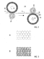
- the three-dimensional facet structures are formed geometrically preferably in that in each case three support elements 50 converging to form a star point (in the view of FIG Fig. 2 not explicitly shown) against the concave side of a trough 2 or dome of the structured layer 12 press and trigger the secondary structuring.
- the in the FIGS. 3A and 3B shown hexagonal or three-dimensional facet-shaped structures have straight folds or webs. These folds or webs may according to a modified embodiment of the invention have a curved shape.
- FIG. 3A illustrates the top view of the vault-structured material web, where wrinkles are made visible as narrow lines.
- the beads of the three-dimensional wave-shaped structures a representation would result in which the lines are formed wider according to the wider-shaped support elements.
- the three-dimensional facets may alternatively be formed with beads (broad lines).
- the binder of the prepreg during the structuring passes with simultaneous curing from the rubber-elastic to the vitreous state (described in US Pat FIGS. 4 and 5 ).
- FIG. 4 shows schematically the viscosity of the binder in the prepreg as a function of the temperature, the reaction conversion and of the time, wherein the variables temperature and time are linked to the specific reaction conversion of the thermosetting prepreg.
- the viscosity decreases with increasing temperature. Only to the right of the vertical line, the viscosity increases steeply, because before reaching the gel point, the cross-linking of the molecules increases significantly.
- the prepreg is in the partially cured state before structuring, ie the curing state of the binder is located in front of the process window. The structuring with further curing takes place in the process window, where a transformation of the prepreg is advantageous.
- FIG. 5 schematically shows the modulus of elasticity of the structuring layer in the cured state.
- the modulus of elasticity decreases sharply. Therefore, the cured patterning layer behaves substantially "rubbery" at high temperatures (above the glass transition point).
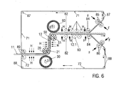
- FIG. 6 schematically shows a further embodiment of the inventive two-stage process for self-structuring a vault structure and a three-dimensional facet-shaped structure in a continuous manufacturing process.
- the supplied structuring layer prepreg 11
- the straps 71, 72 form support layers (see above, FIGS. 1D, E ) and are preferably made of thin metal strip, for example of a stainless steel strip with a thickness of about 0.1 mm.
- the layer structure of upper belt 71, structuring layer 11 and lower belt 72 is then fed to a first structuring unit, consisting of the support element roller 21 and the support elements 20 and the pressure roller 31 with the elastomer layer 30.
- a temperature control of the layer structure supply of heat with heaters H, in particular radiant heaters or inductive radiators may be provided to adjust the temperature of the prepreg in the desired process window.
- the reaction temperature can additionally be set reaction-specifically by the heated pressure element roller 21 and / or by the heating devices H.
- a three-dimensionally wave-shaped structure can be produced in the structuring layer, by additionally forming an elastomer layer (in FIG. 2) between the upper side of the structuring layer and the supporting elements 20 FIG. 6 not shown) or by providing the support elements 20 with such a contour are, as they would result from the self-structuring of the beads in the three-dimensional wave-like structuring.
- the structured patterning layer 12 of the post-structuring (secondary structuring) and the second structuring unit, consisting of the support element roller 51 and its support members 50 and the pressure roller 61 with the elastomer layer 60 is supplied.
- the prepreg is still in the process window, so that advantageously the further structuring can be complete and effective and the risk is reduced or eliminated that fibers break or the tight material composite dissolves.
- the arrangement of the patterning rollers 21 and 51 is selected such that a large angle of wrap occurs.
- the arrangement of the rollers 51 and 61 can also be chosen so that the structuring layer without further deflection, ie directed (analogous to FIG. 2 ), the structuring device leaves (in FIG. 6 not explicitly shown).
- tracking rollers adapted to the structure, chain links and / or elastomer bands, which are circulated and supported by rollers may be provided, as shown downstream of the second structuring unit.
- Pressure rollers 82 hold the composite with the structures 12.1 together, even if for the purpose of final curing nor heating energy to be supplied with a heater H from the outside.
- straightening rollers 83 With the help of straightening rollers 83, the almost cured structuring layer brought into the flatness.
- the upper belt 71 and the lower belt 72 are peeled (peeled off) from the cured patterning layer, deflected by means of deflection rollers 84 and smooth leveling rollers 85, 86, which press with a force F against the structured straps fed.
- the upper belt 71 are returned via the upper deflection rollers 87 and the lower belt 72 via the lower deflection rollers 88.
- a release layer of, for example, PP (polypropylene), PVF (polyvinyl fluoride), or an elastic layer on the top and bottom of the structuring layer may be carried through the process.
- the elastic separating layer can compensate for the possible residual unevenness of the smoothed straps in order to ensure a good surface of the structuring layer.
- the straps may be provided with a release agent.
- the embodiment of the in FIG. 6 shown two-stage process according to the invention can be modified so that the structuring takes place without the straps.
- the curing takes place with a first partial curing at the first structuring unit and a second partial curing at the second structuring unit, wherein in both cases the prepreg is in a state in the process window described above.
- the downstream pressure rollers, chain links or Elastomerb sections can be dispensed with. It is advantageous in this case, a small wrap angle or even the wrap angle of about zero.
- a 21 * 30 mm 2 prepreg was prepared from a fiber material and an unsaturated polyester.
- the Völb Modelltechniksrea, z. B. according to FIG. 1 applied.
- arch structures with a typical structure size of 33 mm were produced.
- the curing of the prepreg took place directly during or after the straightening of the vault-structured layer of the plastic component 10.
- the fiber material used was glass cloth with satin weave 1/7.
- the prepreg has an average thickness of about 0.3 mm.
- the prepreg was sandwiched between two release-treated aluminum sheets (AlMg3 and A199.5 - 0.3 mm thick, respectively) and then fed to the vatting patterning process. In this case, arch structures with 33 mm and 17 mm structure size were produced. Subsequently, the structured prepreg was thermally cured and the sheets removed. For Examples 2 to 5, modified cyanate resins were used.
- the fiber material used was fiberglass fabric of various grammage with satin weave 1/7.
- the resin content of the prepregs varied between 31-48%.
- flexural stiffnesses were determined by means of a 3-point bending test in comparison to flat reference layers (unstructured glass fiber reinforced structuring layers) of the same composition.
- the flexural stiffnesses of the vault-structured glass-fiber-reinforced structuring layers are larger by a factor of 4 to 5 than the flat reference layers.
- the fiber material used was fiberglass nonwovens of different basis weight.
- the resin content of the prepregs was between 50-60%.
- the prepregs had resin contents of about 40-60%.
- hemp fabrics of different basis weight were used.
- the resin content of the prepregs varied between 30-60%.
- the fiber material used were knits made of Nomex fibers with different basis weights.
- the prepregs had resin contents of 60-70%.
- Phenolic resin prepregs with Atlas weave 1/7 glass fiber fabric were used as the reinforcing material.
- the prepregs had resin contents of about 30-70%.
- a prepreg in the format 21 * 30 mm 2 with an average thickness of 0.3 mm was prepared. Thereafter, the prepreg was sandwiched between two release-treated aluminum sheets (AlMg3 and A199.5 - 0.3 mm thick, respectively) and then fed to the vatting patterning process. The curing of the prepregs took place immediately after or after straightening the vault-structured parts. Arch structures with 33 mm and 17 mm structure size were produced. For Example 1, modified cyanate resins were used.
- the fiber material used was fiberglass fabric of various grammage with satin weave 1/7.
- the fiber material used was fiberglass fabric of various grammage with satin weave 1/7.
Landscapes
- Engineering & Computer Science (AREA)
- Mechanical Engineering (AREA)
- Chemical & Material Sciences (AREA)
- Composite Materials (AREA)
- Laminated Bodies (AREA)
- Moulding By Coating Moulds (AREA)
- Casting Or Compression Moulding Of Plastics Or The Like (AREA)
- Reinforced Plastic Materials (AREA)
Description
Die Erfindung betrifft ein Verfahren zur Herstellung eines strukturierten Kunststoffbauteils, insbesondere ein Verfahren zur Selbststrukturierung eines faserverstärkten, insbesondere schichtförmigen Materials (Strukturierungsschicht). Die Erfindung betrifft des Weiteren ein mit diesem Verfahren hergestelltes Kunststoffbauteil, insbesondere ein selbststrukturiertes faserverstärktes Kunststoffbauteil, und dessen Anwendungen.The invention relates to a method for producing a structured plastic component, in particular a method for self-structuring a fiber-reinforced, in particular layer-shaped material (structuring layer). The invention further relates to a plastic component produced by this method, in particular a self-structured fiber-reinforced plastic component, and its applications.
Es ist bekannt, dünnwandige Materialien, wie z. B. Bleche oder Folien einer dreidimensionalen Selbststrukturierung zu unterziehen, beispielsweise um die Steifigkeit, die ästhetische Ansicht oder haptische Eigenschaften des Materials zu verbessern. Die dreidimensionale Selbststrukturierung wird beispielsweise in
Die dreidimensionale Selbststrukturierung wird hier umfassend auch als Wölbstrukturierung oder Beulstrukturierung bezeichnet. Die bei der dreidimensionalen Selbststrukturierung gebildeten Formen werden insbesondere mit den im Folgenden erläuterten Begriffen primäre Wölbstruktur (oder einfach: Wölbstruktur), dreidimensional wellenförmige Struktur und dreidimensionale Facettenstruktur bezeichnet.The three-dimensional self-structuring is here also comprehensively referred to as vault structuring or bulge structuring. The forms formed in the three-dimensional self-structuring are referred to in particular with the terms explained below primary arch structure (or simply: vault structure), three-dimensional wave-shaped structure and three-dimensional facet structure.
Die dreidimensionale Selbststrukturierung ist ein Strukturierungsverfahren, bei dem eine dünne Materialbahn dadurch eine gleichmäßige, versetzte Beulstruktur erhält, dass gekrümmte Wände auf ihrer Innenseite durch Stützringe oder Stützspiralen abgestützt und durch äußeren Überdruck oder inneren Unterdruck beaufschlagt werden (
Unter dreidimensionaler Selbststrukturierung mit der Selbstorganisation der Beulfalten ist somit ein Vorgang zu verstehen, bei dem sich der Werkstoff mehrdimensional nahezu selbstständig faltet, wodurch sich seine Formsteifigkeit verbessert. Dieser Umformprozess des Beulstrukturierens erfolgt beispielsweise in der Weise, dass das gekrümmte, dünnwandige Material, das innen durch im Abstand zueinander angeordnete, starre Stützringe oder durch eine schraubenförmige, starre Stützspirale (
Ein Minimum an plastischer Verformung der Materialbahn tritt dann auf, wenn sich das Material in freier geometrischer Selbsteinstellung verformen kann. Hierzu wird bei der Verformung der Materialbahn mittels einer hydraulischen oder elastischen Druckübertragung die Beulstruktur mittels Stützelementen nur vorgegeben. Im Laufe der geometrischen, dreidimensionalen Strukturierung geben diese Stützelemente nach, so dass die Strukturfalten die Funktion der Stützelemente selbst übernehmen und die Beulfalten und Beulmulden in freier Selbsteinstellung eine solche optimale Form annehmen, dass sie dem herrschenden Verformungsdruck bei minimaler Plastifizierung standhalten (
Beispielsweise kann die dreidimensionale Selbststrukturierung der Materialbahn unter Verwendung von Walzen, welche die Druck- und Stützelemente tragen, kontinuierlich ausgeführt werden. Die so beulstrukturierte und gerichtete Materialbahn wird auch als "primär wölbstrukturiertes" (oder einfach: "wölbstrukturiertes") Material bezeichnet.For example, the three-dimensional self-structuring of the material web can be carried out continuously using rollers which carry the pressure and support elements. The beulstrukturierte and directed web is also referred to as a "primary vault structured" (or simply: "vault structured") material.
Zwischen der zu strukturierenden Materialbahn und der Walze mit den Stützelementen kann auch eine zusätzliche elastomere Materialbahn geführt werden, wie in
Das strukturierte Material kann des Weiteren einer mehrstufigen, insbesondere zweistufigen dreidimensionalen Strukturierung unterzogen werden, insbesondere um räumlich facettenförmige Strukturen zu erzeugen, wie in
Bei der zweistufigen dreidimensionalen Strukturierung wird die zu strukturierende Materialbahn in einem primären Strukturierungsschritt beispielsweise mit sechseckigen Beul- bzw. Wölbstrukturen oder mit dreidimensional wellenförmigen Strukturen versehen, wobei die neutrale Biegelinie durch das Strukturieren aus ihrer ursprünglichen Mittelebene einseitig in Richtung der Mulde bzw. Kalotte verschoben wird. Dadurch entsteht eine häufig unerwünschte Anisotropie, welche beispielsweise den Richtprozess erheblich erschweren kann. Im sekundären Strukturierungsschritt werden die einzelnen Mulden bzw. Kalotten auf ihrer Innenseite durch linienförmige Stützelemente abgestützt und von außen mit Druck beaufschlagt. Bei diesem sekundären "Gegenbeulen" bilden sich dreidimensionale Facettenstrukturen in der Materialbahn aus, die wie aneinander gereihte Würfel oder Pyramidenspitzen aussehen. Das besondere Merkmal dabei ist, dass trotz des dynamischen Durchschlagens beim "Gegenbeulen" nicht wieder stark gekrümmte, d.h. runde, geometrische Strukturen, sondern räumlich angeordnete Strukturflächen entstehen, die überraschenderweise im wesentlichen eben oder bestenfalls nur ganz wenig gekrümmt sind. Deshalb werden die auf diese Weise selbsteinstellend gebildeten geometrischen Strukturen mit "dreidimensionalen Facettenstrukturen" bezeichnet (
Es ist ferner bekannt, Folien oder Bleche mit einem Schichtaufbau (Sandwichkonstruktion) dreidimensional zu strukturieren. So wird z. B. in
Die dreidimensionale Selbststrukturierung zeichnet sich durch das irreversible Einspringen (dynamisches Durchschlagen) des dünnwandigen Materials in den strukturierten Zustand aus, in dem die regelmäßige Anordnung der lokalen Wölbungen (beim primären Wölbstrukturieren) gebildet ist. Zur Realisierung der Selbststrukturierung ist es erforderlich, dass das zu strukturierende, gekrümmte Material dem äußeren Druck zunächst eine elastische Gegenkraft entgegensetzt, um dann nach dem Einspringen durch teilweises Plastifizieren des Werkstoffs - insbesondere im Bereich der Falten oder Wülste - im strukturierten Zustand fixiert zu bleiben. Durch diese Anforderung war die Anwendung der herkömmlichen Verfahren zur Selbststrukturierung bisher auf bestimmte Materialien beschränkt, die den Übergang von einem elastischen in den plastisch deformierten Werkstoffzustand ermöglichen. Zu diesen Materialien zählen beispielsweise Metalle oder thermoplastische Kunststoffe (siehe
Eine Anwendung der Selbststrukturierung war bei ausschließlich elastischen Materialien, beispielsweise Gummi, die lediglich ein reversibles Einspringen in den strukturierten Zustand ermöglichen würden (bei Druckentlastung verschwinden die geometrischen Strukturen wieder), und bei ausschließlich plastisch deformierbaren Materialien, die als Strukturierung lediglich einen erzwungenen Abdruck der Stützelemente ermöglichen oder zerstört werden würden (Rissbildung), ausgeschlossen.One application of self-structuring was to use exclusively elastic materials, for example rubber, which would allow only a reversible jump into the structured state (when pressure is released, the geometric structures disappear again), and in the case of exclusively plastically deformable materials, which only requires a forced impression of the support elements as structuring allow or be destroyed (cracking), excluded.
Aus der Praxis ist auch bekannt, eine Faserschicht mit flüssigem Harz zu tränken und dabei manuell oder mit einer Maschine zwischen Blechen zu laminieren. Die Bleche werden vorgeformt oder beim Laminieren mit der Maschine geformt. Diese Techniken sind jedoch nicht zur oben beschriebenen, selbstorganisierten dreidimensionalen Strukturierung geeignet.From practice it is also known to impregnate a fiber layer with liquid resin and to laminate it manually or with a machine between sheets. The sheets are preformed or formed by machine during lamination. These However, techniques are not suitable for the self-organized three-dimensional structuring described above.
Die Formgebung von Kunststoffbauteilen aus faserverstärktem Harz mittels Pressverfahren, bei denen eine vorgegebene Werkzeugoberfläche in das Kunststoffmaterial gepresst und dieses anschließend ausgehärtet wird, sind aus
Die Aufgabe der Erfindung ist es, ein verbessertes Strukturierungsverfahren anzugeben, mit dem die Nachteile der herkömmlichen Techniken überwunden werden und das einen erweiterten Anwendungsbereich aufweist. Die Aufgabe der Erfindung besteht auch in der Bereitstellung eines verbesserten mehrdimensional strukturierten Kunststoffbauteils.The object of the invention is to provide an improved patterning method, with which the disadvantages of the conventional techniques are overcome and which has an extended scope. The object of the invention is also to provide an improved multi-dimensionally structured plastic component.
Diese.Aufgaben werden durch ein Verfahren und ein Kunststoffbauteil mit den Merkmalen der unabhängigen Ansprüche gelöst. Vorteilhafte Ausführungsformen und Anwendungen der Erfindung ergeben sich aus den abhängigen Ansprüchen.These objects are achieved by a method and a plastic component having the features of the independent claims. Advantageous embodiments and applications of the invention will become apparent from the dependent claims.
Verfahrensbezogen beruht die Erfindung insbesondere auf der technischen Lehre, eine Strukturierungsschicht, die eine Zusammensetzung aus einem Verstärkungsmaterial, vorzugsweise einem textilen Flächengebilde, und einem vernetzbaren Bindemittel enthält, einer Formung zu unterziehen, durch die eine selbststrukturierte dreidimensionale Struktur, insbesondere mit einer primären Wölbstruktur, einer dreidimensionalen wellenförmigen Struktur oder einer dreidimensionalen Facettenstruktur, gebildet wird. Die Zusammensetzung aus Verstärkungsmaterial und vernetzbarem Bindemittel, die chemisch bis zu einer vollständigen Aushärtung umsetzbar ist, wird hier auch als Prepreg bezeichnet. Das Bindemittel umfasst insbesondere ein Prepolymer (typischerweise ein Reaktivharz, das einen Aushärtungsgrad unterhalb eines vorbestimmten kritischen Umsatzes (Gelpunkt) besitzt) oder ein vernetzbares Polymer. Das Prepreg umfasst somit insbesondere ein mit Reaktivharz getränktes und vorvernetztes Faserverstärkungsmaterial (insbesondere textiles Flächengebilde). Das Prepreg ist vorzugsweise in einem nicht-klebrigen Zustand. Das Prepreg stellt ein Halbzeug, d.h. einen Gegenstand dar, der für die Weiterverarbeitung zu einem Fertigerzeugnis bestimmt ist.In terms of method, the invention is based in particular on the technical teaching of subjecting a structuring layer comprising a composition of a reinforcing material, preferably a textile fabric, and a crosslinkable binder, to shaping by which a self-structured three-dimensional structure, in particular with a primary arch structure, is formed three-dimensional wavy structure or a three-dimensional facet structure is formed. The composition of reinforcing material and crosslinkable binder, which is chemically feasible until fully cured, is also referred to herein as prepreg. In particular, the binder comprises a prepolymer (typically a reactive resin having a degree of cure below a predetermined critical conversion (gel point)) or a crosslinkable polymer. The prepreg thus comprises, in particular, a fiber-reinforced material impregnated with reactive resin and precrosslinked (in particular textile fabric). The prepreg is preferably in a non-sticky state. The prepreg represents a semi-finished product, ie an object which is intended for further processing into a finished product.
Die Erfinder haben festgestellt, dass die oben genannten Anforderungen an die Materialien, die der selbstorganisierten, dreidimensionalen Strukturierung unterzogen werden, überraschenderweise unter Verwendung von Prepregs erfüllt werden können. Dabei wirken sich die Vorteile der schonenden Deformation, die für die Selbststrukturierung charakteristisch sind, bei der Bearbeitung von Prepregs besonders vorteilhaft aus. Indem die noch nicht ausgehärtete Strukturierungsschicht, sondern das Halbzeug (Prepreg) der Selbststrukturierung oder einer entsprechenden Abformung unterzogen wird, können die beschriebenen Defizite der bekannten Verfahren beseitigt werden. Das erfindungsgemäße Verfahren kann insbesondere mit den zwei folgenden Verfahrensweisen beschrieben werden.The inventors have found that the above requirements for the materials that undergo the self-organized, three-dimensional structuring can surprisingly be met using prepregs. The advantages of the gentle deformation, which are characteristic of self-structuring, have a particularly advantageous effect in the processing of prepregs. By subjecting the not yet finished structuring layer, but the semifinished product (prepreg) of self-structuring or a corresponding impression, the described deficiencies of the known methods can be eliminated. The method according to the invention can be described in particular with the following two methods.
Gemäß einer ersten Ausführungsvariante kann das teilweise oder nahezu ausgehärtete Prepreg der Selbststrukturierung unterzogen werden, wobei das Bindemittel des Pregregs während dieses Vorgangs vom gummielastischen in einen glasartigen Zustand übergeht (Glasübergang) und sich das Prepreg auf diese Weise ähnlich gut selbststrukturieren lässt wie metallische Werkstoffe. Bei dieser Selbststrukturierung werden bevorzugt materialspezifische Reaktionsbedingungen (so genanntes Prozessfenster) des temperatur- und zeitabhängigen chemischen Reaktionsumsatzes für den Aushärtevorgang des Prepregs eingehalten. Die Reaktionsbedingungen während der dreidimensionalen Strukturierung werden in einem Bereich gewählt, in dem die Viskosität des Prepregs in Abhängigkeit von der Temperatur - parallel zum chemischen Reaktionsumsatz ansteigt (siehe unten,
Gemäß einer zweiten Ausführungsvariante kann das nicht oder nur wenig ausgehärtete Prepreg als Mehrlagenschicht gemeinsam mit mindestens einer Stützschicht, vorzugsweise mit metallischen, dünnen oberen und unteren Gurten der Strukturierung unterzogen werden. Dabei befinden sich die Gurte im elastisch/plastischen Übergangszustand und genügen somit den Anforderungen der Selbststrukturierung. Das zwischen den Gurten eingebettete Prepreg wird dabei mit Hilfe der Gurte isometrisch verformt. Das besondere Merkmal besteht hierbei darin, dass das Prepreg zwischen den Gurten zwar abgeformt wird, jedoch die Vorteile der materialschonenden, mehrdimensionalen dreidimensionalen Selbststrukturierung aufrecht erhalten bleiben. Dabei können sich die Verstärkungsfasern zwischen den Gurten sogar im Bereich der mehrdimensionalen Krümmungen der strukturierten Mehrlagenschicht in mikroskopischen Dimensionen umordnen und verschränken.According to a second embodiment, the non-cured or only slightly cured prepreg may be subjected to the structuring as a multi-layer layer together with at least one support layer, preferably with metallic, thin upper and lower belts. The straps are in the elastic / plastic transition state and thus meet the requirements of self-structuring. The embedded between the straps prepreg is thereby isometrically deformed by means of the straps. The special feature here is that although the prepreg is molded between the straps, the advantages of material-saving, multi-dimensional three-dimensional self-structuring are maintained. The reinforcing fibers between the straps can even rearrange and interlock in microscopic dimensions even in the area of the multidimensional curvatures of the structured multilayer coating.
Auch bei der zweiten Ausführungsvariante erfolgt bei der Aushärtung der Übergang vom gummielastischen in den glasartigen Zustand (Glasübergang), wobei dies jedoch durch die Wirkung der Stützschichten zeitlich nach der Umformung erfolgen kann.In the second embodiment, the transition from the rubber-elastic to the glassy state (glass transition) occurs during curing, but this can be done by the action of the support layers temporally after the forming.
In beiden Fällen kann die geometrische Struktur, insbesondere der primären Wölbstruktur, der dreidimensionalen wellenförmigen Struktur oder der dreidimensionalen Facettenstruktur, gebildet werden. Die dreidimensional wellenförmige Strukturierung kann der primären Wölbstrukturierung vorzuziehen sein, weil die Rundungen der Wülste sanfter sind als die der Falten und so das Verstärkungsmaterial, insbesondere bei Kohlefasern, weniger belastet wird und ferner ein nachfolgender Richtprozess in die ebene Gestalt etwas einfacher wird. Die dreidimensionale Facettenstrukturierung bietet den wesentlichen Vorteil, dass der faserverstärkte und strukturierte Kunststoff nicht nur eine verbesserte isotrope Steifigkeit gewinnt, sondern gleichzeitig mit reduziertem Richtaufwand eine gute Planlage erzielt wird. Vorteilhaft kann das Prinzip der dreidimensionalen Wellenstrukturierung in das dreidimensionale Facettenstrukturieren integriert werden, indem mit Hilfe einer zusätzlichen elastischen Zwischenlage anstatt der Falten die Wülste erzeugt werden.In both cases, the geometric structure, in particular the primary arch structure, the three-dimensional wavy structure or the three-dimensional facet structure can be formed. The three-dimensional wave-like structuring may be preferable to the primary vault structure, because the curves of the beads are gentler than those of the folds, and thus less stress on the reinforcing material, especially in carbon fibers, and also somewhat easier on a subsequent straightening process into the planar shape. The three-dimensional facet structure offers the significant advantage that the fiber-reinforced and structured plastic not only gains an improved isotropic stiffness, but at the same time achieves a good flatness with reduced straightening effort. Advantageously, the principle of three-dimensional wave structuring can be integrated into the three-dimensional facet structure by producing the beads with the aid of an additional elastic intermediate layer instead of the folds.
Ein wichtiger Vorteil der Erfindung besteht darin, dass Faserrisse beim dreidimensionalen Strukturieren vermieden werden und zugleich der faserverstärkte Kunststoff mit einer hohen mehrdimensionalen Formsteifigkeit ausgestattet wird. Die Anwendung der Selbststrukturierung auf Prepregs stellt entsprechend einen erheblichen Fortschritt dar.An important advantage of the invention is that fiber cracks are avoided in the three-dimensional structuring and at the same time the fiber-reinforced plastic is provided with a high multi-dimensional stiffness. The application of self-structuring on prepregs accordingly represents a significant advance.
Vorrichtungsbezogen wird die genannte Aufgabe der Erfindung entsprechend durch die Bereitstellung eines Kunststoffbauteils mit einer Strukturierungsschicht gelöst, die Verstärkungsmaterial und Bindemittel enthält und eine durch Selbstorganisation, insbesondere Selbststrukturierung gebildete Wölbstruktur,insbesondere mit der primären Wölbstruktur, der dreidimensional wellenförmigen Struktur oder der dreidimensionalen Facettenstruktur aufweist. Das Kunststoffbauteil stellt insbesondere ein Leichtbauteil mit einem faserverstärkten Kunststoffmaterial dar, das sich durch mechanische und optische Eigenschaften auszeichnet, die mit faserverstärkten Materialien bisher nicht erreicht wurden. Beispielsweise konnte die Biegesteifigkeit pro Fläche mit einem erfindungsgemäßen Kunststoffbauteil etwa bis zu einem Faktor 20 im Vergleich zu herkömmlichen Schichtmaterialien aus faserverstärktem Kunststoff erhöht werden.In terms of apparatus, the stated object of the invention is correspondingly achieved by providing a plastic component with a structuring layer, the reinforcing material and binder and has a vault structure formed by self-organization, in particular self-structuring, in particular with the primary vault structure, the three-dimensional wave-like structure or the three-dimensional facet structure. The plastic component is in particular a lightweight component with a fiber-reinforced plastic material, which is characterized by mechanical and optical properties that have not yet been achieved with fiber-reinforced materials. For example, the bending stiffness per surface could be increased with a plastic component according to the invention by up to a factor of 20 in comparison to conventional fiber-reinforced plastic layer materials.
Wenn die Selbststrukturierung der Strukturierungsschicht mit den an sich bekannten Selbststrukturierungsverfahren erfolgt, wie sie beispielsweise in
Nach der Wölbstrukturierung kann die Strukturierungsschicht eine Krümmung aufweisen, da durch die Wölbungen die neutrale Biegelinie aus der ursprünglichen Schichtebene herausgeschoben wurde. In Abhängigkeit von der konkreten Anwendung der Erfindung kann diese Krümmung unerwünscht sein. Diese ggf. unerwünschte Krümmung kann mit Hilfe einer elastischen Zwischenlage reduziert werden, wie sie in
Vorzugsweise erfolgt die Bildung der selbststrukturierten dreidimensionalen Struktur (primäre Wölbstrukturen, dreidimensional wellenförmige Strukturen oder dreidimensional facettenförmigen Strukturen) der Strukturierungsschicht gemäß der o. g. ersten Ausführungsvariante durch die Druckbeaufschlagung mittels Selbstorganisation der Strukturierungsschicht.Preferably, the formation of the self-structured three-dimensional structure (primary arch structures, three-dimensional wave-shaped structures or three-dimensional facet-shaped structures) of the structuring layer according to the above-mentioned. first embodiment variant by the pressurization by means of self-organization of the structuring layer.
Alternativ können gemäß ebenfalls der o. g. ersten Ausführungsvariante die ersten oder zweiten Stützelemente als Formwerkzeuge verwendet werden und hierzu eine Geometrie entsprechend einer durch Selbstorganisation gebildeten Struktur aufweisen, so dass die dreidimensionale Strukturierung durch die Druckbeaufschlagung mittels Formung der Strukturierungsschicht durch die ersten oder zweiten Stützelementen erfolgt. In diesem Fall weisen die ersten oder zweiten Stützelemente vorzugsweise Oberflächen auf, deren Konturen aus den an sich bekannten Selbststrukturierungsverfahren topographisch entnommen und geformt sind.Alternatively, according to likewise the above-mentioned first embodiment variant, the first or second support elements can be used as molding tools be used and for this purpose have a geometry corresponding to a structure formed by self-organization, so that the three-dimensional structuring is carried out by the pressurization by forming the structuring layer by the first or second support elements. In this case, the first or second support elements preferably have surfaces whose contours are topographically removed and shaped from the self-structuring methods known per se.
Ein weiterer wichtiger Vorteil der Erfindung besteht darin, dass die Aushärtung des Bindemittels, d.h. die Umwandlung in einen vollständig vernetzten Zustand, entsprechend verschiedenen Gestaltungen der Erfindung während der Selbststrukturierung oder zeitlich nach der Selbststrukturierung erfolgen kann. Die Erfinder haben festgestellt, dass einerseits die dreidimensionale Strukturierung der Strukturierungsschicht und andererseits die Aushärtung der Strukturierungsschicht unabhängig voneinander ausführbar sind. Wenn das Prepreg eine Glastemperatur oberhalb der Umgebungstemperatur aufweist, unter der die weitere Verarbeitung und/oder Anwendung des Kunststoffbauteils erfolgt, typischerweise eine Glastemperatur oberhalb der Raumtemperatur, wie z. B. oberhalb von 50°C, so ist es nicht zwingend erforderlich, dass die Aushärtung sofort während der dreidimensionalen Strukturierung erfolgt.Another important advantage of the invention is that the curing of the binder, i. the conversion to a fully crosslinked state according to various embodiments of the invention during self-patterning or after self-patterning can take place. The inventors have found that, on the one hand, the three-dimensional structuring of the structuring layer and, on the other hand, the curing of the structuring layer can be carried out independently of one another. When the prepreg has a glass transition temperature above the ambient temperature at which the further processing and / or application of the plastic component takes place, typically a glass transition temperature above room temperature, such. B. above 50 ° C, it is not absolutely necessary that the curing takes place immediately during the three-dimensional structuring.
Wenn die Aushärtung des Bindemittels während der dreidimensionalen Strukturierung beginnt oder erfolgt, so kann dies Vorteile für eine schnelle und effektive Prozessführung haben. Eine Aushärtungseinrichtung vorzugsweise mit integrierter Temperierung (für die chemische Umsatz-Reaktion) kann insbesondere in die Kombination aus Druckelementen - und dreidimensionalen Stützelementen integriert sein. Auf diese Weise kann gleichzeitig ein ausreichender Anpressdruck für den innigen Faser/Kunststoff-Verbund erzeugt werden, so dass mit einer einzigen Maschine ein fertig strukturiertes Kunststoffbauteil herstellbar ist. Wenn die Aushärtung nach der dreidimensionalen Strukturierung erfolgt, können sich Vorteile für die schonende Umformung der Strukturierungsschicht während der dreidimensionalen Strukturierung und/oder die vergrößerte Variabilität bei einer eventuellen Weiterverarbeitung ergeben. Die Aushärtung nach der dreidimensionalen Strukturierung kann bedeuten, dass die Aushärtung zeitlich unmittelbar nach der Strukturierung, d.h. ohne Zwischenschaltung weiterer Verfahrensschritte erfolgt. Die selbststrukturierte Strukturierungsschicht wird beim Austritt aus der Kombination aus Stütz- und Druckelementen direkt in einer Aushärtungseinrichtung angeordnet und dort der Aushärtung unterzogen. Alternativ können zwischen der dreidimensionalen Strukturierung und der Aushärtung Zwischenschritte vorgesehen sein, die beispielsweise die Anpassung des Kunststoffbauteils an die geometrischen, mechanischen, optischen oder weiteren Anforderungen einer konkreten Anwendung umfassen. Wenn die Aushärtung durch eine Erwärmung der Strukturierungsschicht bewirkt wird, so kann die Erwärmung insbesondere bei kontinuierlicher Prozessführung in Abhängigkeit von der Geschwindigkeit des chemischen Aushärtens und der Transportgeschwindigkeit der Strukturierungsschicht bereits vor der dreidimensionalen Strukturierung begonnen werden. Damit wird vorteilhafterweise eine Verzögerung vermieden, die durch einen in der Regel instationären Wärmefluss von einer Heizquelle in die Strukturierungsschicht verursacht werden würde.If the curing of the binder begins or occurs during three-dimensional structuring, this can have advantages for fast and effective process control. A curing device, preferably with integrated temperature control (for the chemical conversion reaction), can be integrated in particular into the combination of printing elements and three-dimensional support elements. In this way, at the same time a sufficient contact pressure for the intimate Fiber / plastic composite are produced so that a finished structured plastic component can be produced with a single machine. If the curing takes place after the three-dimensional structuring, there may be advantages for the gentle shaping of the structuring layer during the three-dimensional structuring and / or the increased variability in a possible further processing. The curing after the three-dimensional structuring may mean that the curing takes place temporally immediately after the structuring, ie without the interposition of further process steps. The self-structured structuring layer is arranged directly on exit from the combination of support and pressure elements in a curing device and there subjected to the curing. Alternatively, intermediate steps can be provided between the three-dimensional structuring and the curing, which include, for example, the adaptation of the plastic component to the geometric, mechanical, optical or other requirements of a specific application. If the curing is effected by heating the structuring layer, the heating can be started even before the three-dimensional structuring, in particular with continuous process control, depending on the rate of chemical curing and the transport speed of the structuring layer. This advantageously avoids a delay which would be caused by a normally unsteady heat flow from a heating source into the structuring layer.
Wenn die oben genannte zweistufige Selbststrukturierung mit einer primären Wölbstruktur bzw. dreidimensional wellenförmigen Strukturierung und einer anschließenden Nachstrukturierung vorgesehen ist, kann die Aushärtung entsprechend während oder nach der Nachstrukturierung vorgesehen sein.If the abovementioned two-stage self-structuring with a primary arch structure or a three-dimensional corrugated structuring and a subsequent post-structuring is provided, the curing may be provided accordingly during or after the post-structuring.
Ein erfindungsgemäßes Kunststoffbauteil umfasst die Zusammensetzung aus Verstärkungsmaterial und Bindemittel entsprechend mit einem Zustand des Bindemittels, das (nach der Aushärtung) vollständig vernetzt ist, so dass ein Kunststoff gebildet wird. Alternativ kann das Kunststoffbauteil nur teilweise ausgehärtet oder wie während der dreidimensionalen Strukturierung teilvernetzt sein und vernetzbares Bindemittel enthalten.A plastic component according to the invention comprises the composition of reinforcing material and binder corresponding to a condition of the binder, which is fully crosslinked (after curing), so that a plastic is formed. Alternatively, the plastic component may be only partially cured or partially crosslinked as during the three-dimensional structuring and contain crosslinkable binder.
Gemäß bevorzugten Gestaltungen der Erfindung umfasst die Aushärtung des Bindemittels eine thermische Behandlung der Strukturierungsschicht, eine strahlenchemische Behandlung der Strukturierungsschicht oder eine Kombination aus diesen. Vorteilhafterweise können hierzu an sich verfügbare Aushärtungseinrichtungen, wie z. B. Heizeinrichtungen und/oder Bestrahlungseinrichtungen, wie z. B. UV-Lichtquellen verwendet werden.According to preferred embodiments of the invention, the curing of the binder comprises a thermal treatment of the structuring layer, a radiation-chemical treatment of the structuring layer or a combination thereof. Advantageously, for this purpose available hardening facilities such. B. heaters and / or irradiation facilities, such as. B. UV light sources can be used.
Ein weiterer wichtiger Vorteil der Erfindung besteht in der hohen Gestaltungsfreiheit bei der Bereitstellung der Strukturierungsschicht zwischen den Druck- und Stützelementen. Gemäß einer ersten Variante der Erfindung wird ausschließlich die Strukturierungsschicht, bestehend aus der Zusammensetzung aus Verstärkungsmaterial und vernetzbarem Bindemittel der Selbststrukturierung unterzogen. In diesem Fall wird vorzugsweise ein trockenes, nicht-klebriges Prepreg der Selbststrukturierung unterzogen. Die Erfinder haben festgestellt, dass ein zu dem oben beschriebenen Einspringen herkömmlich verwendeter Materialien in den strukturierten Zustand ähnliches Verhalten mit teilweise vernetzten Bindemitteln, insbesondere teilvernetzten Harzen realisierbar ist. Die Selbststrukturierung einzelner Strukturierungsschichten hat Vorteile insbesondere in Bezug auf die einfache Verfahrensführung und die Bereitstellung besonders leichter Kunststoffbauteile.Another important advantage of the invention is the high degree of design freedom in providing the structuring layer between the printing and supporting elements. According to a first variant of the invention, only the structuring layer consisting of the composition of reinforcing material and crosslinkable binder is subjected to self-structuring. In this case, it is preferable to subject a dry, non-tacky prepreg to self-patterning. The inventors have found that a behavior similar to the above-described insertion of conventionally used materials into the structured state can be achieved with partially cross-linked binders, in particular partially cross-linked resins. The self-structuring of individual structuring layers has advantages in particular in terms of simple process management and the provision of particularly lightweight plastic components.
Gemäß der o. g. zweiten Ausführungsvariante der Erfindung kann die Strukturierungsschicht als Teil eines Schichtaufbaus zwischen den Druck- und Stützelementen angeordnet werden. Der Schichtaufbau umfasst mindestens eine Stützschicht, die entsprechend mindestens einseitig mit der Strukturierungsschicht verbunden ist, die das Verstärkungsmaterial und das vernetzbare Bindemittel enthält. Die mindestens eine Stützschicht umfasst ein Material, das zur Selbststrukturierung geeignet ist. Vorteilhafterweise kann durch die Kombination der Strukturierungsschicht mit der mindestens einen Stützschicht die selbstorganisierende Strukturierung der Strukturierungsschicht unterstützt werden.According to the o. G. In the second variant of the invention, the structuring layer can be arranged as part of a layer structure between the pressure and support elements. The layer structure comprises at least one support layer, which is correspondingly connected at least on one side to the structuring layer containing the reinforcing material and the crosslinkable binder. The at least one support layer comprises a material which is suitable for self-structuring. Advantageously, the self-organizing structuring of the structuring layer can be supported by the combination of the structuring layer with the at least one support layer.
Es sind vorzugsweise zwei Stützschichten vorgesehen, zwischen denen die Strukturierungsschicht während der dreidimensionalen Selbststrukturierung angeordnet ist. Die Einbettung der Strukturierungsschicht zwischen zwei Stützschichten hat vorteilhafterweise drei Wirkungen, die einzeln oder in Kombination die mechanischen Eigenschaften des erfindungsgemäßen Kunststoffbauteils verbessern. Die erste Wirkung besteht in der Unterstützung des Einspringens der Strukturierungsschicht in die geometrischen Strukturen, beispielsweise primären Wölbstruktur. Damit kann erfindungsgemäß erleichtert werden, dass Prepregs der Selbststrukturierung unterzogen werden können. Eventuelle Beschränkungen hinsichtlich der Materialeigenschaften werden überwunden. Die zweite Wirkung besteht darin, dass die Stützschichten bei der Selbststrukturierung eine Relativbewegung in Bezug auf die Strukturierungsschicht ausführen. Im Ergebnis wird das Verstärkungsmaterial, insbesondere das Fasermaterial, in der Strukturierungsschicht verschränkt, so dass die mechanischen Eigenschaften des Kunststoffbauteils, insbesondere die Zug- und Reißfestigkeit erheblich verbessert werden. Die dritte Wirkung besteht darin, dass zwischen der Strukturierungsschicht und den Stützschichten insbesondere während der Selbststrukturierung ein Reibschluss besteht. Durch die gegenseitige Reibung werden Kräfte insbesondere an den Stegen oder Falten der strukturierten Strukturierungsschicht abgeleitet, so dass die Deformation des Prepregs besonders schonend erfolgt. Die Verminderung der Deformation der Prepregs auf ein Minimum ist insbesondere bei Prepregs, die riss- oder bruchempfindliche Fasern enthalten, von Vorteil.Two support layers are preferably provided, between which the structuring layer is arranged during the three-dimensional self-patterning. The embedding of the structuring layer between two support layers advantageously has three effects which, individually or in combination, improve the mechanical properties of the plastic component according to the invention. The first effect is to aid in the process of breaking the patterning layer into the geometric structures, for example, primary dome structure. Thus, it can be facilitated according to the invention that prepregs can be subjected to self-structuring. Any restrictions on the material properties are overcome. The second effect is that the self-structuring support layers make relative movement with respect to the patterning layer. As a result, the reinforcing material, in particular the fiber material, is entangled in the structuring layer, so that the mechanical properties the plastic component, in particular the tensile and tear strength can be significantly improved. The third effect is that a frictional engagement exists between the structuring layer and the support layers, in particular during the self-structuring. Due to the mutual friction forces are derived in particular at the webs or folds of the structured structuring layer, so that the deformation of the prepreg is particularly gentle. Reduction of the deformation of the prepregs to a minimum is particularly advantageous for prepregs containing crack or fragile fibers.
Vorzugsweise ist mindestens eine Stützschicht aus einem metallischen Material und/oder einem Kunststoffmaterial hergestellt. Erfindungsgemäß können alle Metalle oder Legierungen verwendet werden, die den gewünschten elastischen-plastischen Übergangsbereich für das Einspringen der selbstorganisierenden Struktur aufweisen, wie z. B. Stahl oder Aluminium. Eine Kunststoff-Stützschicht besteht vorzugsweise aus einem thermoplastischen Werkstoff wie z. B. PVC.Preferably, at least one support layer is made of a metallic material and / or a plastic material. According to the invention, all metals or alloys can be used which have the desired elastic-plastic transition region for the insertion of the self-organizing structure, such as. As steel or aluminum. A plastic backing layer is preferably made of a thermoplastic material such. B. PVC.
Vorteilhafterweise kann die mindestens eine Stützschicht gelocht sein. In diesem Fall können sich Vorteile durch eine unmittelbare Einwirkung einer Aushärtungseinrichtung auf die Strukturierungsschicht, z. B. Bestrahlung, oder durch eine Gewichtsersparnis ergeben. Aus metallischen Materialien hergestellte Stützschichten haben den zusätzlichen Vorteil, dass sie für eine induktive Heizung der Strukturierungsschicht verwendet werden können.Advantageously, the at least one support layer may be perforated. In this case, advantages can be achieved by an immediate action of a curing device on the patterning layer, for. B. irradiation, or by a weight saving. Support layers made of metallic materials have the additional advantage that they can be used for inductive heating of the patterning layer.
Vorteilhafterweise kann die mindestens eine Stützschicht nicht nur zur Unterstützung der Selbststrukturierung der Strukturierungsschicht mit den obengenannten Wirkungen, sondern als eigenständiger Bestandteil des erfindungsgemäßen Kunststoffbauteils vorgesehen sein. Entsprechend umfasst gemäß einer bevorzugten Ausführungsform der Erfindung das Kunststoffbauteil die selbststrukturierte Strukturierungsschicht, die mindestens einseitig mit einer identisch selbststrukturierten Stützschicht, vorzugsweise auf der Grundlage von Metall oder Kunststoff, verbunden ist. Alternativ kann eine Trennung der Strukturierungsschicht von der mindestens einen Stützschicht nach der Selbststrukturierung, vorzugsweise nach der Aushärtung vorgesehen sein. In diesem Fall trägt gemäß einer weiteren bevorzugten Gestaltung der Erfindung die Strukturierungsschicht oder die mindestens eine Stützschicht mindestens einseitig ein haftverminderndes Mittel, wie z.B. PTFE oder Silikon.Advantageously, the at least one support layer can not only support the self-structuring of the patterning layer with the above-mentioned effects, but as an independent part of the invention Be provided plastic component. Accordingly, according to a preferred embodiment of the invention, the plastic component comprises the self-structured structuring layer, which is connected at least on one side with an identically self-structured support layer, preferably based on metal or plastic. Alternatively, a separation of the structuring layer from the at least one support layer may be provided after the self-structuring, preferably after the curing. In this case, according to a further preferred embodiment of the invention, the structuring layer or the at least one support layer at least on one side carries an adhesion-reducing agent, such as PTFE or silicone.
Gemäß einer weiteren Variante der Erfindung kann die Strukturierungsschicht als Teil eines Schichtaufbaus zwischen den Druck- und Stützelementen angeordnet werden, wobei eine elastische Zusatzschicht zwischen den Stützelementen, insbesondere der Stützelementwalze (siehe unten) und der Strukturierungsschicht verwendet wird. In diesem Fall ergeben sich insbesondere dann Vorteile, wenn die Zusatzschicht später nicht mehr als fester Bestandteil des wölbstrukturierten Kunststoffbauteils benötigt wird. Der Vorteil der elastischen Zusatzschicht besteht ferner darin, dass sie in analoger Weise wie die festen Stützschichten (z. B. aus Metall oder Kunststoff) ein materialschonendes Verschränken der Fasern in der Strukturierungsschicht ermöglicht und darüber hinaus wiederverwendbar ist. Die elastische Zusatzschicht kann gemäß einer bevorzugten Variante mit den Stützelementen fest verbunden, d. h. integraler Bestandteil der Walze mit den Stützelementen sein.According to a further variant of the invention, the structuring layer can be arranged as part of a layer structure between the pressure and support elements, wherein an elastic additional layer between the support elements, in particular the support element roller (see below) and the structuring layer is used. In this case, particular advantages arise when the additional layer is no longer needed later as a solid part of the vault structured plastic component. The advantage of the elastic additional layer is also that it allows a material-friendly entanglement of the fibers in the structuring layer in an analogous manner as the solid support layers (eg., From metal or plastic) and beyond reusable. The elastic additional layer can according to a preferred variant firmly connected to the support elements, d. H. be an integral part of the roller with the support elements.
Zusätzlich kann zwischen der Zusatzschicht und der Strukturierungsschicht eine dünne Folie, z. B. aus Kunststoff vorgesehen sein, die sich nach dem Strukturieren wieder leicht von der strukturierten Strukturierungsschicht abziehen lässt.In addition, between the additional layer and the patterning layer, a thin film, for. B. made of plastic which, after structuring, can easily be removed again from the structured structuring layer.
Gemäß einer weiteren Variante der Erfindung bilden die Stützelemente ein Werkzeug mit einer starren geometrischen Werkzeugoberfläche, die so gebildet ist, dass sie der Oberflächengestalt der selbststrukturierten Strukturierungsschicht entspricht. Die Stützelemente sind so geformt, wie die durch Selbstorganisation gebildete geometrische Struktur der Strukturierungsschicht. Diese Formung kann exakt oder angenähert vorgesehen sein. Eine näherungsweise Formung entsprechend der gewünschten Gestalt der Strukturierungsschicht ist bspw. gegeben, wenn die Stützelemente komplementär zur Form und Ausrichtung der Wölbungen der strukturierten Strukturierungsschicht ausgerichtet sind. Vorteilhafterweise wird damit ebenfalls eine riss- oder bruchfreie Verschränkung von Fasern in der Strukturierungsschicht erreicht. Diese Verschränkung kann mit einer dünnen Folie zwischen der Strukturierungsschicht und den Stützelementen begünstigt werden. Es kann vorgesehen sein, dass diese Folie nach der Selbststrukturierung vom Kunststoffbauteil abgezogen wird.According to a further variant of the invention, the support elements form a tool with a rigid geometric tool surface, which is formed so that it corresponds to the surface shape of the self-structured structuring layer. The support elements are shaped in the same way as the self-organized geometric structure of the structuring layer. This shaping can be provided exactly or approximately. An approximate shaping according to the desired shape of the structuring layer is provided, for example, if the support elements are aligned complementary to the shape and orientation of the convexities of the structured structuring layer. Advantageously, this also achieves a crack-free or break-free entanglement of fibers in the structuring layer. This entanglement can be promoted with a thin film between the patterning layer and the support elements. It can be provided that this film is removed after the self-structuring of the plastic component.
Vorteilhafterweise ist die Umsetzung der Erfindung nicht auf die Verwendung bestimmter Verstärkungsmaterialien in der Strukturierungsschicht beschränkt. Es können insbesondere Naturfasern oder synthetische Fasern verwendet werden. Die Verwendung von Zellulosefasern, Glasfasern, Textilfasern, Kohlefasern oder Zusammensetzungen aus diesen hat den besonderen Vorteil, dass diese Faserarten die erfindungsgemäß verwendete Selbststrukturierung besonders gut tolerieren.Advantageously, the implementation of the invention is not limited to the use of certain reinforcing materials in the structuring layer. In particular, natural fibers or synthetic fibers can be used. The use of cellulose fibers, glass fibers, textile fibers, carbon fibers or compositions of these has the particular advantage that these types of fibers tolerate the self-structuring used according to the invention particularly well.
Besondere Vorteile für die Verfahrensführung ergeben sich, wenn als Fasermaterial faserhaltige Flächenhalbzeuge verwendet werden, die z. B. Vliese, Filze, Gewebe, Geflechte, Gestricke, Gelege oder Kombinationen aus diesen umfassen. Die Verwendung von insbesondere textilen Flächenhalbzeugen ermöglicht, dass das erfindungsgemäße Verfahren mit einem Vorbereitungsschritt ausgeführt wird, bei dem das Flächenhalbzeug mit dem vernetzbaren Bindemittel getränkt wird, bevor die Zusammensetzung aus dem Verstärkungsmaterial und dem Bindemittel der Selbststrukturierung unterzogen wird.Special advantages for the process result, if used as fiber material fibrous semi-finished products, the z. Nonwovens, felts, fabrics, braids, Knitted fabrics, scrims or combinations of these include. The use of textile semifinished textile products in particular makes it possible to carry out the method according to the invention with a preparatory step in which the semifinished product is impregnated with the cross-linkable binder before the composition of the reinforcing material and the binder is subjected to self-structuring.
Wenn als faserhaltiges Flächenhalbzeug Papier verwendet wird, ergeben sich besondere Vorteile insbesondere für die Leichtbautechnik. Papier kann mit einer besonders geringen Dicke bereitgestellt, mit dem Bindemittel getränkt und anschließend der Selbststrukturierung unterzogen werden.If paper is used as the fibrous semifinished product, special advantages result, in particular for the lightweight construction technique. Paper can be provided with a particularly small thickness, impregnated with the binder and then subjected to self-structuring.
Das erfindungsgemäß in der Strukturierungsschicht verwendete Bindemittel umfasst vorzugsweise ein vernetzbares Polymer, ein Prepolymer, eine Kombination eines vernetzbaren Polymers oder eines Prepolymers mit einem thermoplastischen Material und/oder mit einem elastomeren Material, eine Verbindung mit chemisch reaktionsfähigen Gruppen oder eine Kombination aus diesen.The binder used in the patterning layer according to the invention preferably comprises a crosslinkable polymer, a prepolymer, a combination of a crosslinkable polymer or a prepolymer with a thermoplastic material and / or with an elastomeric material, a compound with chemically reactive groups or a combination thereof.
Gemäß bevorzugten Varianten der Erfindung ist das Bindemittel mindestens einer der nachfolgend genannten Stoffklassen oder deren Kombinationen zuzuordnen: Phenolharze, Melaminharze, Harnstoffharze, Urethane, Isocyanate, Epoxidharze, Acrylate, ungesättigte Polyester, Polyester, Vinylester, Silikonharze bzw. -Kautschuke, Cyanatharze, Bismaleimide, Maleimidharze, Benzoxazine, Perfluorcyclobutane, Biscyclobutane.According to preferred variants of the invention, the binder is assigned to at least one of the following substance classes or combinations thereof: phenolic resins, melamine resins, urea resins, urethanes, isocyanates, epoxy resins, acrylates, unsaturated polyesters, polyesters, vinyl esters, silicone resins, cyanate resins, bismaleimides, Maleimide resins, benzoxazines, perfluorocyclobutanes, biscyclobutanes.
Vorteilhafterweise können diese Substanzen durch die Aushärtung der Strukturierungsschicht in einen Duroplast- oder einen Elastomer-Werkstoff mit veränderter Vernetzungsdichte umgesetzt werden, so dass das erfindungsgemäße Kunststoffbauteil mit den jeweils gewünschten mechanischen Eigenschaften von Duroplasten oder Elastomeren ausgestattet sein kann.Advantageously, these substances can be converted by the curing of the patterning layer in a thermoset or an elastomer material with modified crosslinking density, so that the plastic component according to the invention can be equipped with the particular desired mechanical properties of thermosets or elastomers.
Wenn die erfindungsgemäß strukturierte Strukturierungsschicht zusätzlich zu dem Verstärkungsmaterial und dem Bindemittel ein thermoplastisches Polymer enthält, wie z.B. Polyester, Polycarbonat, Polymethacrylat, Polypropylen, Polyethylen können die mechanisch-elastischen Eigenschaften des fertigen Kunststoffbauteils vorteilhafterweise zusätzlich beeinflusst werden.When the structuring layer structured according to the invention contains, in addition to the reinforcing material and the binder, a thermoplastic polymer, e.g. Polyester, polycarbonate, polymethacrylate, polypropylene, polyethylene, the mechanical elastic properties of the finished plastic component can advantageously be additionally influenced.
Bei weiteren Varianten der Erfindung kann vorgesehen sein, dass die Strukturierungsschicht aus einer einzigen Lage der Zusammensetzung aus Verstärkungsmaterial und Bindemittel besteht oder alternativ mehrlagig gebildet ist. Der einlagige Aufbau hat Vorteile insbesondere für den Leichtbau, während der mehrlagige Aufbau vorteilhafterweise die Kombination verschiedener Verstärkungsmaterialien und/oder Bindemittel ermöglicht. In diesem Fall können bestimmte funktionelle Eigenschaften des fertigen Kunststoffbauteils eingestellt werden.In further variants of the invention it can be provided that the structuring layer consists of a single layer of the composition of reinforcing material and binder or alternatively is formed in multiple layers. The single-layer construction has advantages, in particular for lightweight construction, while the multilayer structure advantageously makes it possible to combine different reinforcing materials and / or binders. In this case, certain functional properties of the finished plastic component can be adjusted.
Gemäß einer besonders bevorzugten Ausführungsform der Erfindung umfasst das Strukturierungsverfahren einen kontinuierlichen Prozess, bei dem die Strukturierungsschicht als langgestreckte Materialbahn zwischen umlaufenden Walzen durchgeführt wird, welche die Stütz- und Druckelemente tragen, so dass vorteilhafterweise besonders großflächige Bauteile hergestellt werden können. Zur besonders schonenden Umformung der Strukturierungsschicht kann auf wenigstens einer der Walzen eine elastische Zwischenschicht vorgesehen sein. Vorteilhafterweise wird dadurch verhindert, dass die Strukturierungsschicht mit den typischerweise metallischen Stützelementen in direkte Berührung kommt, so dass die Umformung besonders werkstoffschonend erfolgt. Gleichzeitig werden damit die Konturen (Falten) mit einer besonders sanften Rundung versehen. Weil die Höhe der geometrischen Strukturen aufrechterhalten bleiben kann, wird vorteilhafterweise vermieden, dass es zu Einbußen der hohen Biegesteifigkeit der strukturierten Strukturierungsschicht kommt.According to a particularly preferred embodiment of the invention, the structuring method comprises a continuous process, in which the structuring layer is carried out as an elongated material web between revolving rollers, which support the support and pressure elements, so that advantageously particularly large-area components can be produced. For particularly gentle shaping of the structuring layer, an elastic intermediate layer may be provided on at least one of the rollers. Advantageously, this prevents that the patterning layer comes into direct contact with the typically metallic support elements, so that the deformation takes place particularly gentle on the material. At the same time, the Contours (wrinkles) provided with a particularly gentle curve. Because the height of the geometric structures can be maintained, it is advantageously avoided that the high flexural stiffness of the structured structuring layer is impaired.
Die Realisierung einer kontinuierlichen Prozessführung stellt einen wesentlichen Vorteil der Erfindung dar. Im Gegensatz zu herkömmlichen Techniken, bei denen eine Verarbeitung von Prepregs stets diskontinuierlich erfolgt, wird erfindungsgemäß erstmalig eine kontinuierliche Formung von Prepregs bereitgestellt.The realization of a continuous process control represents a significant advantage of the invention. In contrast to conventional techniques, in which a processing of prepreg always takes place discontinuously, the invention provides for the first time a continuous shaping of prepregs.
Gemäß einer weiteren Ausführungsform der Erfindung kann die strukturierte Schicht vor oder nach der Aushärtung einer Nachbearbeitung unterzogen werden, um das fertige erfindungsgemäße Kunststoffbauteil herzustellen. Die Nachbearbeitung umfasst vorzugsweise eine Randbearbeitung, eine Zerlegung in Einzelteile, eine Verbindung mit weiteren Kunststoffbauteilen, eine Beschichtung, die Aushärtung oder eine Kombination aus diesen Verfahren. Zur Randbearbeitung kann vorgesehen sein, dass an der Strukturierungsschicht ein- oder mehrseitig ein ebener (nicht strukturierter) oder feinstrukturierter Rand gebildet wird, der sich auf das Verbinden mit weiteren Strukturierungsschichten, wie z. B. durch mechanisches, thermisches oder chemisches Fügen vorteilhaft auswirkt.According to a further embodiment of the invention, the structured layer may be subjected to post-processing before or after curing in order to produce the finished plastic component according to the invention. The post-processing preferably comprises edge processing, disassembly into individual parts, a connection with other plastic components, a coating, the curing or a combination of these methods. For edge processing can be provided that on the structuring layer on one or more pages a flat (not structured) or finely textured edge is formed, which is based on the connection with further structuring layers such. B. advantageous by mechanical, thermal or chemical joining.
Die Verbindung mit weiteren Kunststoffbauteilen kann die Bildung eines Sandwich-Aufbaus mit mehreren Lagen von übereinander liegenden, z. B. verklebten Materialbahnen aufweist, wobei nur eine oder mehrere innen liegende Kernlagen die erfindungsgemäß gebildete Struktur aufweisen. Es kann ein Verbundaufbau aus mehreren unterschiedlichen Werkstoffen, z. B. aus faserverstärktem Kunststoff und Metall, z. B. Aluminium oder Stahl gebildet werden.The connection with other plastic components, the formation of a sandwich construction with multiple layers of superimposed, z. B. bonded webs, wherein only one or more inner core layers have the structure formed according to the invention. It may be a composite structure of several different materials, eg. B. off fiber reinforced plastic and metal, e.g. As aluminum or steel are formed.
Bevorzugte Anwendungen des Kunststoffbauteils gemäß der Erfindung, das insbesondere mindestens eine versteifte, ausgehärtete Strukturierungsschicht enthält, bestehen bei der Bereitstellung schallabsorbierender Eigenschaften, z. B. in Bauwerken oder Fahrzeugen, im Leichtbau, in der Installationstechnik, z. B. bei der Verkleidung von Rohren oder Kanälen, als thermostabiles Bauteil, als Gehäusebauteil, insbesondere im Fahrzeugbau, zur Crash-Absorption und/oder als Gestaltungselement.Preferred applications of the plastic component according to the invention, which contains in particular at least one stiffened, hardened structuring layer, consist in the provision of sound-absorbing properties, e.g. B. in buildings or vehicles, in lightweight construction, in installation technology, z. As in the cladding of pipes or channels, as a thermostable component, as a housing component, in particular in vehicle construction, for crash absorption and / or as a design element.
Die Erkenntnisse der Erfinder können mit den folgenden Gesichtspunkten zusammengefasst werden. Erfindungsgemäß wird ein Kunststoffbauteil bereitgestellt, das sich durch eine allseitige (d. h. in mehreren Raumrichtungen der Strukturierungsschicht) Formsteifigkeit und eine besonders materialschonende (insbesondere die Fasern schonende), aus der Ebene der Strukturierungsschicht (in die "dritte Dimension") herausführende dreidimensionale Strukturierung, wobei sich ein hohes Flächenträgheitsmoment ergibt, auszeichnet. Um diese Vorteile zu erreichen, werden die drei folgenden Merkmalskomplexe vorzugsweise zugleich realisiert.
- (a) Weil sich textile Flächengebilde (lange Fasern, die durch verschiedene Bindungen miteinander verknüpft sind), insbesondere Kohlefasern, nicht dehnen oder plastifizieren und knicken (oder eng biegen) lassen, und dennoch eine mehrdimensionale Versteifung erzielt werden soll, wird eine so genannte isometrische Umformung bereitgestellt (d. h. der Flächeninhalt wird durch das Strukturieren nicht verändert), die zugleich nur sanfte Biegeradien, dafür aber vergleichsweise tiefe Strukturen (hohes mechanisches Flächenträgheitsmoment) aufweist. Dafür ist eine geometrische Raffung der Strukturierungsschicht aus einer ebenen Fläche in zugleich mehreren Richtungen erforderlich, was mit den herkömmlichen Umformtechniken mittels geometrisch komplexen Werkzeugen in der Regel deshalb nicht möglich ist, weil deren geometrische Konturen das zu-verformende dünnwandige Material beim Umformprozess "einsperren" und dadurch erheblich dehnen. Bei den rissempfindlichen faserverstärkten Kunststoffen ist das nicht möglich. Ferner ist das Bindemittel noch nicht vollständig ausgehärtet, weil Duromere nicht umformbar bzw. plastifizierbar sind.
- (b) Die Fasern können sich durch Umorientierungen und Verschränkungen in Mikrodimensionen schonend der mehrdimensional isometrischen Umformung (nach Punkt a) anpassen.
- (c) Während der Umformung und Strukturierung wird entlang des zeitlichen chemischen Reaktionsablaufs (Aushärtungsvorgang) ein Andrücken oder Zusammendrücken der Strukturierungsschicht oder eines Schichtaufbaus mit der Strukturierungsschicht aufrechterhalten, um eine Lockerung des Verbundes der Strukturierungsschicht (z. B. infolge Umformung, Kriechverhalten und Relaxation und bei denkbarer Schrumpfung/Gasabspaltung) und ferner Einbußen von der erzeugten geometrischen Steifigkeit (Reduzierung der dritten Dimension) zu verhindern und eine gute Oberflächenbeschaffenheit zu erzeugen. Durch Einstellung der Reaktionsbedingungen werden Einbußen der geometrischen Steifigkeit vermieden.
- (a) Because fabrics (long fibers interlinked by different bonds), especially carbon fibers, do not stretch or plasticize and buckle (or bend tightly), and yet multi-dimensional stiffening is to be achieved, so-called isometric Forming provided (ie the surface is not changed by the structuring), which at the same time only gentle bending radii, but rather comparatively deep structures (high mechanical moment of inertia) having. For a geometric gathering of the structuring layer of a flat surface in several directions is required, which is therefore usually not possible with the conventional forming techniques using geometrically complex tools, because their geometric contours "lock in" the to-deforming thin-walled material during the forming process and stretch considerably. This is not possible with the crack-sensitive fiber-reinforced plastics. Furthermore, the binder is not fully cured because thermosets are not deformable or plasticizable.
- (b) The fibers can be adapted by reorientation and entanglement in microdimensions gently the multidimensional isometric transformation (after point a).
- (c) During shaping and structuring, a pressing or compressing of the structuring layer or of a layer structure with the structuring layer is maintained along the temporal chemical reaction sequence (hardening process) in order to ease the structuring of the structure of the structuring layer (for example as a result of deformation, creep behavior and relaxation and relaxation) at conceivable shrinkage / gas separation) and further losses of the generated geometric rigidity (reduction of the third dimension) to prevent and to produce a good surface finish. By adjusting the reaction conditions, losses of geometric rigidity are avoided.
Überraschenderweise konnten diese drei Merkmalskomplexe mit dem erfindungsgemäßen Verfahren zugleich realisiert werden, indem die Selbststrukturierung (auf der Basis einer kontrollierten Selbstorganisation) unter Ausnutzung der spezifischen Werkstoffeigenschaften des aushärtenden Prepregs (Variablen: Zeit, Temperatur und chemischer Reaktionsumsatz) und mit einer Prozessführung in Kombination mit einem Andrücken und Aushärten auf faserverstärkten Kunststoff angewendet wird.Surprisingly, these three feature complexes could at the same time be realized with the method according to the invention by using the self-structuring (on the basis of a controlled self-assembly) by utilizing the specific material properties of the thermosetting prepreg (variables: Time, temperature and chemical reaction conversion) and with a process control in combination with a pressing and curing on fiber-reinforced plastic is applied.
Mit Hilfe der Selbststrukturierung der dreidimensionalen Strukturierungsformen (primäres Wölbstrukturieren, dreidimensional wellenförmiges Strukturieren, dreidimensional facettenförmiges Strukturieren) kann die Strukturierungsschicht für die Erzeugung der dritten Dimension zugleich in mehreren Richtungen gerafft werden, weil der mittlere Durchmesser der zylindrisch gekrümmten, zunächst glatten (das heißt nichtstrukturierten) Materialbahn durch das "Durchschlagen" (beim Strukturierungsprozeß) etwas kleiner wird, durch die "lichte" (das heißt gemittelte) zylindrische Fläche etwas kleiner wird und auf diese Weise diese frei werdende Differenzfläche für die Erzeugung der mehrdimensionalen Struktur/dritte Dimension zur Verfügung gestellt wird. Dadurch wird die isometrische mehrdimensionale Umformung/Versteifung realisiert, wobei dies vorteilhafterweise sogar ohne aufwendige Formwerkzeuge möglich ist, welche die Strukturierungsschicht dehnen und die Fasern zerreißen würden.With the help of the self-structuring of the three-dimensional structuring forms (primary vault structuring, three-dimensional wavy structuring, three-dimensional facet-shaped structuring), the structuring layer for the generation of the third dimension can be gathered in several directions at the same time, because the average diameter of the cylindrically curved, initially smooth (that is, unstructured) Material web through the "strike through" (the structuring process) is slightly smaller, through the "light" (that is, averaged) cylindrical surface is slightly smaller, and thus this released differential area for the creation of the multi-dimensional structure / third dimension is provided , As a result, the isometric multi-dimensional deformation / stiffening is realized, and this is advantageously possible even without elaborate molding tools which would stretch the structuring layer and rupture the fibers.
Der mehrdimensionale isometrische Effekt des "Durchschlagens" gelingt mit Hilfe der vorzugsweise metallischen Gurte (Werkstoff im elastischen/plastischen Übergangsbereich) oder auch dann, wenn (ohne Gurte) das nahezu ausgehärtete Prepreg selbst für die Strukturierung sich in einem Vernetzungszustand unmittelbar vor dem Glaszustand befindet. Die Umformung des Prepregs gelingt, da das Bindemittel während der Strukturierung und dem Aushärten vom gummielastischen in den glasartigen Zustand übergeht (Glasübergang). Im letzteren Fall wird die chemische Redaktionszeit entsprechend gewählt, um das oben beschriebene Prozessfenster zu realisieren.The multi-dimensional isometric effect of "puncturing" succeeds with the aid of preferably metallic straps (material in the elastic / plastic transition region) or even if (without straps) the nearly cured prepreg itself is in a crosslinking state immediately before the glass state for the structuring. The forming of the prepreg succeeds as the binder transitions from the rubber-elastic to the glassy state during structuring and curing (glass transition). In the latter case, the chemical editorial time is selected accordingly in order to realize the process window described above.
Wegen der isometrischen Umformung (nach a) werden die Fasern von selbst nur umgelagert/ verschränkt, wobei die Viskosität des Bindemittels (
Das Andrücken oder Zusammendrücken der Strukturierungsschicht gemäß (c) gelingt mit Hilfe stützender Maßnahmen, wie Gurten, vorzugsweise aus Metall. Die metallischen Gurte können auf dem fertig ausgehärteten faserverstärkten Kunststoff verbleiben und ergeben als Sandwich ein Endprodukt, beispielsweise für Luftfahrzeuge. Die Gurte können aber auch vorteilhaft nach dem vollständigen Aushärten des Prepregs (Fertigprodukt) wieder abgezogen werden, dann im Kreislauf eines kontinuierlichen Strukturierungsprozesses zurückgeführt und somit wiederverwendet werden (Vermeidung von Ausschuss, wenn die Gurtschichten im Rahmen des Endprodukts nicht mehr benötigt werden). Hierfür werden die strukturierten Gurte (nach dem Abschälen vom ausgehärteten Prepreg) mit Hilfe von glatten Walzen wieder geglättet. Alternativ können Gurte aus anderen Werkstoffen, vorzugsweise im elastisch/plastischen Übergangsverhalten, wie temperaturstabile Thermoplaste oder Gewebeschichten, verwendet werden.The pressing or compression of the structuring layer according to (c) is achieved by means of supporting measures, such as straps, preferably of metal. The metallic straps may remain on the finished cured fiber reinforced plastic and provide as a sandwich an end product, for example for aircraft. However, the straps can also advantageously be removed again after the prepreg has completely cured (finished product), then recycled in the course of a continuous structuring process and thus reused (avoidance of rejects if the belt layers are no longer needed in the context of the end product). For this purpose, the structured belts (after peeling from the cured prepreg) with the aid of smooth rollers are smoothed again. Alternatively belts of other materials, preferably in elastic / plastic transition behavior, such as temperature-stable thermoplastics or fabric layers can be used.
Es wird vorzugsweise ein zeitlich möglichst langer Berührungskontakt zwischen der Strukturierungsschicht und der Strukturierungswalze (vorzugsweise geheizt) realisiert, indem ein möglichst großer Umschlingungsgrad der Strukturierungsschicht um die Strukturierungswalze bei gleichzeitiger kurzer chemischer Reaktionszeit (von wenigen Sekunden) bereitgestellt wird. Ein großer Umschlingungsgrad ist vorzugsweise so gebildet, dass die Strukturierungsschicht um 180° um die Strukturierungswalze gebogen wird, wobei sich die Laufrichtung der Strukturierungsschicht vollständig (zu 180°) umkehrt. Beispielsweise erfolgt ein mittlerer Umschlingungsgrad von 90°, wenn die Strukturierungsschicht um 90° um die Strukturierungswalze gebogen wird. Ein kleiner Umschlingungsgrad von wenigen Graden erfolgt vorzugsweise dann, wenn - insbesondere bei fast ausgehärtetem Prepreg - die Strukturierungsschicht nur noch wenig umgelenkt werden soll. Jedoch soll hierbei der minimale Umschlingungswinkel (beim primären Wölbstrukturieren) vorzugsweise etwa gleich oder größer demjenigen Winkel sein, der sich einstellt, wenn die elastische Druckwalze gegen die Strukturierungsschicht drückt und der Gummiabdruck in Umfangsrichtung gerade einer einzelnen gebildeten Wölbstruktur entspricht. Wenn dieser Gummiabdruck deutlich kleiner ist, sind die Voraussetzungen für die Selbststrukturierung ("Plopp-Effekt" aus der Krümmung) nicht mehr gegeben und es entstehen dann häufig die unerwünschten, geometrisch verzerrten Strukturen.Preferably, the contact contact between the structuring layer and the structuring roller that is as long as possible (preferably heated) is realized by providing the greatest possible degree of entanglement of the structuring layer around the structuring roller with simultaneous short chemical reaction time (of a few seconds) becomes. A large degree of wrap is preferably formed so that the patterning layer is bent by 180 ° about the patterning roller, wherein the running direction of the structuring layer reverses completely (180 °). For example, an average degree of wrap of 90 ° occurs when the structuring layer is bent by 90 ° about the structuring roller. A small degree of wrap of a few degrees is preferably carried out when - especially with almost cured prepreg - the patterning layer is to be deflected only slightly. However, in this case, the minimum wrap angle (in the primary vault patterning) should preferably be about equal to or greater than the angle that occurs when the elastic pressure roll presses against the patterning layer and the rubber impression in the circumferential direction just corresponds to a single formed dome structure. If this rubber impression is significantly smaller, the prerequisites for self-structuring ("popping effect" from the curvature) no longer exist and then often the unwanted, geometrically distorted structures arise.
Gemäß einer weiteren Variante können, falls die Kontaktzeit für die chemische Reaktionszeit an den Strukturierungwalzen nicht ausreicht, bei der Strukturierung mitlaufende, der Struktur angepasste Andruckrollen, Kettenglieder und/oder Elastomerbänder, die im Kreislauf geführt und durch Rollen gestützt werden, mit integrierter Heizung vorgesehen sein.According to a further variant, if the contact time for the chemical reaction time on the structuring rollers is not sufficient, structurally matched pinch rollers, chain links and / or elastomeric bands, which are circulated and supported by rollers, can be provided with integrated heating ,
Das Richten der strukturierten Materialbahn in die Planlage wird wesentlich durch das dreidimensionale wellenförmige Strukturieren erleichtert, weil sich die Strukturierungsschicht beim Strukturieren nicht so eng an die Strukturierungswalze anschmiegt wie beim primären Wölbstrukturieren.The straightening of the structured material web in the flat position is substantially facilitated by the three-dimensional wavy structuring, because the structuring layer does not conform as closely to the structuring roller during structuring as in the case of primary arch structuring.
Das Richten der strukturierten Materialbahn in die Planlage wird durch das sekundäre, gegengerichtete Durchschlagen beim dreidimensional facettenförmigen Strukturieren von selbst fast völlig erledigt. Ein Nachrichten in die exakte Ebene der Planlage kann wegen des nicht auszuschließenden Relaxationsverhaltens bei der letzten Endaushärtung/Abkühlung in bestimmten Anwendungsfällen dennoch erforderlich sein.The directing of the structured material web into the flat position is almost completely done by the secondary, counter-directed puncturing during the three-dimensional facet-shaped structuring by itself. A message in the exact plane of the plan position may still be required because of the non-excludable relaxation behavior in the final final curing / cooling in certain applications.
Weitere Einzelheiten und Vorteile der Erfindung werden im Folgenden unter Bezug auf die beigefügten Zeichnungen beschrieben. Es zeigen:
- Figuren 1A bis 1F:
- eine erste Ausführungsform des erfindungsgemäßen Verfahrens zur Selbststrukturierung von Strukturierungsschichten;
- Figur 2:
- eine weitere Ausführungsform des erfindungsgemäßen Verfahrens zur Selbststrukturierung von Strukturierungsschichten,
- Figur 3:
- Beispiele von Oberflächen strukturierter Kunststoffbauteile gemäß der Erfindung,
- Figur 4:
- eine schematische graphische Darstellung der Viskosität des Bindemittels in Abhängigkeit von der Temperatur,
- Figur 5:
- eine schematische graphische Darstellung des Elastizitätsmoduls eines gehärteten Prepregs in Abhängigkeit von der Temperatur, und
- Figur 6:
- eine weitere Ausführungsform des erfindungsgemäßen Verfahrens zur kontinuierlichen Selbststrukturierung von Strukturierungsschichten.
- FIGS. 1A to 1F:
- a first embodiment of the method according to the invention for the self-structuring of patterning layers;
- FIG. 2:
- a further embodiment of the method according to the invention for the self-structuring of structuring layers,
- FIG. 3:
- Examples of surfaces of structured plastic components according to the invention,
- FIG. 4:
- a schematic graph of the viscosity of the binder as a function of the temperature,
- FIG. 5:
- a schematic graph of the modulus of elasticity of a cured prepreg as a function of the temperature, and
- FIG. 6:
- a further embodiment of the method according to the invention for continuous Self-structuring of structuring layers.
Ausführungsformen der Erfindung werden im Folgenden unter Bezug auf die erfindungsgemäß verwendeten Materialien und die Besonderheiten beschrieben, die sich aus der Verwendung dieser Materialien für das Verfahren der Selbststrukturierung ergeben. Einzelheiten des Vorgangs der Selbststrukturierung und der hierfür verwendeten Maschinen sind aus dem Stand der Technik bekannt und werden daher hier nicht erläutert. Vielmehr werden insbesondere die
Die in der Strukturierungsschicht erfindungsgemäß gebildete, selbstorganisierte Struktur wird kaum durch Materialeigenschaften, sondern hauptsächlich durch die Geometrie der Selbstorganisation, induziert durch die Geometrie der Stützelemente festgelegt. Entsprechend kann die für die konkrete Anwendung gewünschte Struktur der Strukturierungsschicht maßgeblich durch die Auswahl der Struktur der Stützelemente gewählt werden, wie dies von den herkömmlichen Verfahren zur Selbststrukturierung bekannt ist.The self-assembled structure formed in the patterning layer according to the invention is hardly determined by material properties, but mainly by the geometry of the self-assembly induced by the geometry of the support elements. Correspondingly, the structure of the structuring layer desired for the specific application can be selected decisively by the selection of the structure of the support elements, as is known from the conventional methods for self-structuring.
Es wird betont, dass die in den Figuren gezeigten Werkzeuge zur kontinuierlichen Selbststrukturierung von Strukturierungsschichten nicht zwingend zur Umsetzung der Erfindung vorgesehen sind. Das kontinuierliche Verfahren kann durch ein diskontinuierliches Verfahren insbesondere mit Werkzeugen ersetzt werden, welche die Stützelemente und das Druckelement ersetzen. Das Druckelement wird nicht zwingend durch eine elastische Fläche bereitgestellt, sondern kann alternativ durch eine Einrichtung zur Erzeugung eines hydrostatischen oder pneumatischen Druckes (so genanntes Wirkmedium) gebildet werden.It is emphasized that the tools shown in the figures for the continuous self-structuring of patterning layers are not necessarily intended to implement the invention. The continuous process can be replaced by a batch process, in particular with tools comprising the support elements and the pressure element replace. The pressure element is not necessarily provided by an elastic surface, but may alternatively by a device for generating a hydrostatic or pneumatic pressure (so-called active medium) are formed.
Die Beschreibung erfolgt unter Bezug auf die Variante der Erfindung, bei der die Stützelemente eine selbstorganisierte Wölbung der Strukturierungsschicht auslösen. Die Realisierung der alternativen Variante, bei der die Stützelemente ein Werkzeug mit einer starren geometrischen Werkzeugoberfläche bilden, erfolgt analog.The description is made with reference to the variant of the invention in which the support elements trigger a self-organized curvature of the structuring layer. The realization of the alternative variant, in which the support elements form a tool with a rigid geometric tool surface, takes place analogously.
Die Aushärtungseinrichtung 40 umfasst z. B. eine elektrische Konvektions- oder Strahlungsheizung oder, insbesondere bei der Verwendung metallischer Stützschichten (siehe
Die Vorrichtung 100 ist vorzugsweise so angeordnet, dass die strukturierte Materialbahn des Kunststoffbauteils 10 sich als wölbstrukturiertes Material eng an die Krümmung der Strukturelemente 20 anschmiegt und besonders bevorzugt die Vorrichtung 100 stark nach unten gebogen verlässt (in der schematischen Darstellung nicht explizit dargestellt). Im Falle der dreidimensional wellenförmigen Strukturierung wird zwischen der Strukturierungsschicht und den Stützelementen 20 eine zusätzliche Elastomerschicht geführt. In diesem Fall verlässt die strukturierte Materialbahn nur schwach nach unten gekrümmt, im Wesentlichen geringfügig vorgerichtet, die Vorrichtung 100.The
Die Strukturierungsschicht 11 ist vorzugsweise mit einem ein- oder mehrlagigen Aufbau gebildet und/oder mit weiteren Schichten kombiniert, wie dies schematisch in den
Gemäß
Gemäß
Gemäß
Schließlich illustriert
Die Strukturierung der Strukturierungsschicht 11 zur Erzeugung des Kunststoffbauteils 10 erfolgt mit den folgenden Arbeitsschritten. Zunächst wird die Strukturierungsschicht 11 im nicht-ausgehärteten Zustand z. B. gemäß
Durch den dabei auf die Strukturierungsschicht 11 aufgeprägten'Druck kommt es zum Einspringen der Strukturierungsschicht 11 in den strukturierten Zustand, wobei sich Mulden 2 bilden, die durch Stege 1 voneinander getrennt sind. Die Umformung in den strukturierten Zustand erfolgt, ohne dass die Strukturierungsschicht 11 im Bereich der Mulden 2 eine feste Werkzeugfläche berühren. Die Mulden 2 sind zu der unteren Oberfläche 13 der Strukturierungsschicht 11 weisend gebildet und haben entsprechend eine in Bezug auf die obere Oberfläche 14 konkave Form.As a result of the pressure impressed on the
Die Durchlaufgeschwindigkeit der Materialbahn zwischen den Stütz- und Druckwalzen 21, 31 beträgt z. B. 0,1 bis 0,2 m/s, kann aber auch höher oder niedriger eingestellt werden. Die Durchlaufgeschwindigkeit kann insbesondere in Abhängigkeit von der Aushärtgeschwindigkeit des konkret gewählten Kunststoffes eingestellt werden. In einem weiteren Arbeitsschritt, der zeitgleich mit der Selbststrukturierung oder daran anschließend vorgesehen sein kann, erfolgt die integrierte Erwärmung des Schichtaufbaus 70 zum Aushärten des Bindemittels in der Strukturierungsschicht 11.The passage speed of the material web between the support and
Noch vor der Aushärtung oder bei geeigneten Materialeigenschaften nach der Aushärtung folgt ein Richten des Schichtaufbaus 70 und ggf. eine Trennung der Stützschichten 71, 72 von der Strukturierungsschicht 11.Before curing or with suitable material properties after curing, straightening of the
Mit der in
Gemäß der o. g. ersten Ausführungsvariante geht das Bindemittel des Pregregs während der Strukturierung mit gleichzeitiger Aushärtung vom gummielastischen in den glasartigen Zustand über (beschrieben in den
Durch Druckbelastung der ersten Strukturierungseinheit springen Wölbungen in die Strukturierungsschicht 11 ein. Im Ergebnis wird die strukturierte Strukturierungsschicht 12 erzeugt. Die Reaktionstemperatur kann zusätzlich durch die beheizte Druckelementwalze 21 und/oder durch die Heizvorrichtungen H reaktionsspezifisch eingestellt werden. Alternativ kann in der ersten Strukturierungseinheit eine dreidimensional wellenförmige Struktur in der Strukturierungsschicht erzeugt werden, indem zusätzlich zwischen der Oberseite der Strukturierungsschicht und den Stützelementen 20 eine Elastomerschicht (in
Anschließend wird die strukturierte Strukturierungsschicht 12 der Nachstrukturierung (Sekundärstrukturierung) and der zweiten Strukturierungseinheit, bestehend aus der Stützelementwalze 51 und ihren Stützelementen 50 sowie der Druckwalze 61 mit der Elastomerschicht 60 zugeführt. Hierbei ist besonders bevorzugt vorgesehen, dass sich das Prepreg noch im Prozessfenster befindet, so dass vorteilhafterweise die weitere Strukturierung vollständig und effektiv erfolgen kann und die Gefahr vermindert oder ausgeschlossen wird, dass Fasern reißen oder der enge Materialverbund sich löst. Durch Druckbeaufschlagung entstehen vorzugsweise die dreidimensional facettenförmigen Strukturen 12.1 (
Gemäß
Erfindungsgemäß können bei der Strukturierung mitlaufende, der Struktur angepasste Andruckrollen, Kettenglieder und/oder Elastomerbänder, die im Kreislauf geführt und durch Rollen gestützt werden, vorgesehen sein, wie prozessabwärts nach der zweiten Strukturierungseinheit gezeigt ist. Druckrollen 82 halten den Verbund mit den Strukturen 12.1 zusammen, selbst wenn zwecks Endaushärtung noch Heizenergie mit einer Heizvorrichtung H von außen zugeführt werden soll. Mit Hilfe von Richtrollen 83 wird die nahezu ausgehärtete Strukturierungsschicht in die Planlage gebracht. Anschließend werden der obere Gurt 71 und der untere Gurt 72 von der ausgehärteten Strukturierungsschicht abgezogen (abgeschält), mit Hilfe von Umlenkrollen 84 umgelenkt und glatten Planierungswalzen 85, 86, die mit einer Kraft F gegen die strukturierten Gurte drücken, zugeführt. Im eingeebneten Zustand werden der obere Gurt 71 über die oberen Umlenkrollen 87 und der untere Gurt 72 über die unteren Umlenkrollen 88 zurückgeführt.According to the invention, during the structuring, tracking rollers adapted to the structure, chain links and / or elastomer bands, which are circulated and supported by rollers, may be provided, as shown downstream of the second structuring unit.
Um die Trennung der Gurte von der Strukturierungsschicht zu erleichtern, kann eine Trennschicht beispielsweise aus PP (Polypropylen), PVF (Polyvinylfluorid) oder eine elastische Schicht auf der Ober- und Unterseite der Strukturierungsschicht durch den Prozess mitgeführt werden. Dabei kann die elastische Trennschicht die möglichen Restunebenheiten der geglätteten Gurte ausgleichen, um eine gute Oberfläche der Strukturierungsschicht zu gewährleisten. Alternativ können die Gurte mit einem Trennmittel versehen sein.To facilitate the separation of the straps from the structuring layer, a release layer of, for example, PP (polypropylene), PVF (polyvinyl fluoride), or an elastic layer on the top and bottom of the structuring layer may be carried through the process. In this case, the elastic separating layer can compensate for the possible residual unevenness of the smoothed straps in order to ensure a good surface of the structuring layer. Alternatively, the straps may be provided with a release agent.
Die Ausführungsform des in
Die Anwendbarkeit des Wölbstrukturierens auf Strukturierungsschichten bestehend aus einem Fasermaterial und einem vernetzbaren Bindemittel wurde mit den folgenden Beispielen demonstriert.The applicability of Völbstrukturierens on patterning layers consisting of a fiber material and a crosslinkable Binder was demonstrated by the following examples.
Zuerst wurde aus einem Fasermaterial und einem ungesättigten Polyester ein Prepreg des Formats 21 * 30 mm2 hergestellt. Auf dieses Prepreg wurde der Wölbstrukturierungsprozess, z. B. gemäß
Als Fasermaterial wurde Glasfasergewebe mit Atlasbindung 1/7 verwendet. Das Prepreg hat eine mittlere Dicke von ca. 0,3 mm.The fiber material used was glass cloth with
Zunächst wurde aus einem Fasermaterial und einem Reaktivharz ein Prepreg im Format 21 * 30 mm2, mit einer mittleren Dicke von 0,3 mm, hergestellt. Im Folgenden wurde das Prepreg zwischen zwei mit Trennmittel behandelte Aluminiumbleche (AlMg3 bzw. A199,5 - 0,3 mm dick) gelegt und dann dem Wölbstrukturierungsprozess zugeführt. Dabei wurden Wölbstrukturen mit 33 mm und 17 mm Strukturgröße erzeugt. Anschließend wurde das strukturierte Prepreg thermisch ausgehärtet und die Bleche entfernt. Für die Beispiele 2 bis 5 wurden modifizierte Cyanatharze verwendet.First, a prepreg in the format of 21 * 30 mm 2 , with an average thickness of 0.3 mm, was prepared from a fiber material and a reactive resin. In the following, the prepreg was sandwiched between two release-treated aluminum sheets (AlMg3 and A199.5 - 0.3 mm thick, respectively) and then fed to the vatting patterning process. In this case, arch structures with 33 mm and 17 mm structure size were produced. Subsequently, the structured prepreg was thermally cured and the sheets removed. For Examples 2 to 5, modified cyanate resins were used.
Als Fasermaterial kam Glasfasergewebe verschiedenen Flächengewichts mit Atlasbindung 1/7 zum Einsatz. Der Harzgehalt der Prepregs variierte zwischen 31-48 %. An den ausgehärteten wölbstrukturierten glasfaserverstärkten Strukturierungsschichten wurden Biegesteifigkeiten mittels 3-Punkt-Biegeversuch im Vergleich zu ebenen Referenzschichten (unstrukturierte glasfaserverstärkte Strukturierungsschichten) der selben Zusammensetzung bestimmt. Die Biegesteifigkeiten der wölbstrukturierten glasfaserverstärkten Strukturierungsschichten sind gegenüber den ebenen Referenzschichten um den Faktor 4 bis 5 größer.The fiber material used was fiberglass fabric of various grammage with
Als Fasermaterial wurden Glasfaservliese verschiedenen Flächengewichts eingesetzt. Der Harzgehalt der Prepregs lag zwischen 50-60 %.The fiber material used was fiberglass nonwovens of different basis weight. The resin content of the prepregs was between 50-60%.
Als Verstärkungsmaterialien wurden Papiere verschiedenen Flächengewichts benutzt. Die Prepregs wiesen Harzgehalte von ca. 40-60 % auf.As reinforcing materials papers of different basis weight were used. The prepregs had resin contents of about 40-60%.
Als Fasermaterial wurden Hanfgewebe verschiedenen Flächengewichts eingesetzt. Der Harzgehalt der Prepregs variierte zwischen 30-60 %.As fiber material, hemp fabrics of different basis weight were used. The resin content of the prepregs varied between 30-60%.
Als Fasermaterial kamen Gestricke aus Nomexfasern mit verschiedenen Flächengewichten zum Einsatz. Die Prepregs wiesen Harzgehalte von 60-70 % auf.The fiber material used were knits made of Nomex fibers with different basis weights. The prepregs had resin contents of 60-70%.
Es wurden Phenolharzprepregs mit Glasfasergewebe in Atlasbindung 1/7 als Verstärkungsmaterial benutzt. Die Prepregs wiesen Harzgehalte von ca. 30-70 % auf.Phenolic resin prepregs with
Aus einem Fasermaterial und einem Reaktivharz wurde ein Prepreg im Format 21 * 30 mm2 mit einer mittleren Dicke von 0,3 mm hergestellt. Danach wurde das Prepreg zwischen zwei mit Trennmittel behandelte Aluminiumbleche (AlMg3 bzw. A199,5 - 0,3 mm dick) gelegt und dann dem Wölbstrukturierungsprozess zugeführt. Die Aushärtung der Prepregs erfolgte unmittelbar beim oder nach dem Richten der wölbstrukturierten Teile. Es wurden Wölbstrukturen mit 33 mm und 17 mm Strukturgröße erzeugt. Für das Beispiel 1 wurden modifizierte Cyanatharze verwendet.From a fiber material and a reactive resin, a prepreg in the
Als Fasermaterial kam Glasfasergewebe verschiedenen Flächengewichts mit Atlasbindung 1/7 zum Einsatz.The fiber material used was fiberglass fabric of various grammage with
Aus einem Fasermaterial und einem Reaktivharz wurde ein Prepreg im Format 21 * 30 mm2 mit einer mittleren Dicke von 0,3 mm hergestellt. Danach wurde jedes einzelne Prepreg zwischen zwei Aluminiumbleche (AlMg3 bzw. A199,5 - 0,3 mm dick) gelegt, wobei nur eines der Bleche mit Trennmittel behandelt war, und dann dem Wölbstrukturierungsprozess zugeführt. Nach der anschließenden Aushärtung wurde das mit Trennmittel behandelte Blech von dem "Sandwich" entfernt. Es entstand auf diese Weise ein wölbstrukturierter Verbund aus Metall und einer faserverstärkten Strukturierungsschicht mit einer Wölbstrukturgröße von 33 mm. Für das Beispiel 1 wurden modifizierte Cyanatharze verwendet.From a fiber material and a reactive resin was a prepreg in the
Als Fasermaterial kam Glasfasergewebe verschiedenen Flächengewichts mit Atlasbindung 1/7 zum Einsatz.The fiber material used was fiberglass fabric of various grammage with
Claims (41)
- A method for producing a plastic component (10), comprising the steps of:- providing a structuring layer (11, 12) between first supporting elements (20) and a first pressure element (30), and- vault-structuring the structuring layer (11, 12), wherein the vault-structuring of the structuring layer (11, 12) comprises the steps of:- supporting the structuring layer (11, 12) on a first surface (13) by the first supporting elements (20), and- applying pressure to the structuring layer (11, 12) on the opposing, second surface (14) between the first supporting elements (20) by the first pressure element (30), such that vaults (2) of a vault structure established by self-organisation form in the structuring layer (11, 12) between the first supporting elements (20),
characterized in that- the structuring layer (11, 12) contains a composition prepared from a reinforcing material and a crosslinkable binder, and- curing of the structuring layer (11, 12) is provided during or after the vault-structuring. - The method according to claim 1, in which, after the vault-structuring, the structuring layer (12) is arranged between second supporting elements (50) and a second pressure element (60) and subjected to post-structuring by applying pressure to the structuring layer (12).
- The method according to claim 2, in which the post-structuring proceeds with an inverse orientation with regard to the preceding vault-structuring.
- The method according to at least one of the preceding claims, in which the vault-structuring and/or the post-structuring by applying pressure proceeds by means of self-organisation of the structuring layer (11, 12).
- The method according to at least one of claims 1 to 3, in which the first or second supporting elements (20, 50) exhibit a geometry corresponding to a vault structure formed by self-organisation and the vault-structuring proceeds by applying pressure by means of forming the structuring layer (11, 12) by the first or second supporting elements (20, 50).
- The method according to claim 2, in which the curing of the structuring layer (12) is provided during or after post-structuring.
- The method according to at least one of the preceding claims, in which the curing proceeds by a thermal and/or radiation-chemical treatment of the structuring layer (11, 12).
- The method according to at least one of the preceding claims, in which the curing comprises a transition of the composition made of the reinforcing material and the binder from a rubber-elastic to a vitreous state.
- The method according to at least one of the preceding claims, in which providing the structuring layer (11) comprises arranging solely the structuring layer (11) between the first supporting elements (20) and the first pressure element (30).
- The method according to at least one of claims 1 to 7, in which providing the structuring layer (11) comprises arranging a layer structure (70), which contains the structuring layer (11) and at least one supporting layer (71, 72), between the first supporting elements (20) and the first pressure element (30), wherein the vault-structuring and/or post-structuring proceed by applying pressure by means of self-organisation of the at least one supporting layer (71, 72) and/or of the structuring layer (11, 12).
- The method according to claim 10, in which the layer structure (70) comprises a first supporting layer (71), the structuring layer (11) and a second supporting layer (72).
- The method according to claim 10 or claim 11, in which the at least one supporting layer comprises at least one metal layer and/or at least one plastic film.
- The method according to claim 12, in which the metal layer comprises steel sheet or aluminium sheet.
- The method according to claim 12 or claim 13, in which inductive heating of the at least one metal layer is provided for curing the structuring layer.
- The method according to at least one of claims 10 to 14, in which the at least one supporting layer (71, 72) is perforated.
- The method according to at least one of claims 10 to 15, in which an adhesion-reducing agent (73, 74) is applied onto at least one side of the structuring layer (11) or of the at least one supporting layer (71, 72).
- The method according to at least one of claims 10 to 16, in which arranging the layer structure (70) comprises bringing together upper and lower belts (71, 72), which form the supporting layers, and the structuring layer (11).
- The method according to claim 17, in which, after the vault-structuring or the post-structuring, the belts (71, 72) are smoothed and supplied to a continuous process for arranging the layer structure (70).
- The method according to at least one of the preceding claims, in which the fibre material contains natural fibres or synthetic fibres.
- The method according to claim 19, in which cellulose fibres, glass fibres, textile fibres and/or carbon fibre are used as the fibres.
- The method according to at least one of the preceding claims, in which semi-finished textiles are used as the fibre material.
- The method according to at least one of the preceding claims, in which the crosslinkable binder used is:(a) a crosslinkable polymer,(b) a prepolymer,(c) a combination of a crosslinkable polymer or of a prepolymer with a thermoplastic material,(d) a combination of a crosslinkable polymer or of a prepolymer with an elastomeric material,(e) a compound with chemically reactive groups, or(f) a combination of at least two binders according to (a) to (e).
- The method according to claim 22, in which the crosslinkable binder used is at least one substance which is selected from the group which comprises phenolic resins, melamine resins, urea resins, urethanes, isocyanates, epoxy resins, acrylates, unsaturated polyesters, polyesters, vinyl esters, silicone resins or rubbers, cyanate resins, bismaleimides, maleimide resins, benzoxazines, perfluorocyclobutanes and biscyclobutanes.
- The method according to at least one of the preceding claims, in which the curing comprises a reaction of the structuring layer to yield a thermoset or an elastomer.
- The method according to at least one of the preceding claims, in which a multi-ply structuring layer (15) is subjected to the vault-structuring.
- The method according to at least one of the preceding claims, in which the structuring layer (11, 12) comprises a material web and the provision and vault-structuring of the structuring layer (11, 12) proceed continuously, wherein the first supporting elements (20) are arranged on the circumferential surface of a rotatable supporting roller (21), while the first pressure element (30) is formed by a resilient circumferential surface of a pressure roller (31) and wherein the structuring layer (11, 12) is passed for vault-structuring between the supporting roller (21) and the pressure roller (31).
- The method according to at least one of the preceding claims, in which a resilient interlayer is arranged between the structuring layer (11, 12) and at least one of the first or second supporting elements (20, 50) and first or second pressure elements (30, 60).
- The method according to at least one of the preceding claims, in which the structuring layer (11, 12) is subjected to post-processing which comprises at least one of forming, division, joining with a further structuring layer, edging and coating.
- The method according to at least one of the preceding claims, in which the composition prepared from the reinforcing material and the crosslinkable binder comprises a prepreg.
- A plastic component which comprises a structuring layer with a vault structure, formed by self-organisation, of the structuring layer,
characterized in that the structuring layer comprises a composition prepared from a reinforcing material and a crosslinked binder. - The plastic component according to claim 30, in which the reinforcing material comprises natural fibres or synthetic fibres.
- The plastic component according to claim 31, in which the fibre material comprises cellulose fibres, glass fibres, textile fibres and/or carbon fibres.
- The plastic component according to at least one of claims 30 to 32, in which the fibre material comprises semi-finished textiles.
- The plastic component according to at least one of claims 30 to 33, in which the plastic component contains a thermoset or an elastomer.
- The plastic component according to at least one of claims 30 to 34, in which the structuring layer is single ply.
- The plastic component according to at least one of claims 30 to 36, in which the structuring layer is multi-ply.
- The plastic component according to claim 36, in which the structuring layer contains a thermoplastic polymer.
- The plastic component according to at least one of claims 30 to 37 which has a sandwich structure comprising a plurality of plies of material webs lying one upon the other, wherein only one or a plurality of internal core plies have a vault structure.
- The plastic component according to claim 38, which has a composite structure prepared from a plurality of different materials.
- The plastic component according to claim 39, which has a composite structure of plastic and metal.
- Use of a plastic component which is produced by a method according to at least one of claims 1 to 29, or of a plastic component according to at least one of claims 30 to 40 as:- a sound-absorbing component,- a lightweight wall,- an installation component, in particular for pipes or ducts,- a thermally stable component for use under fluctuating temperatures,- a housing component for machinery and vehicles, in particular aircraft, railway vehicles or spacecraft,- an impact-absorbing component, and/or- a design element, in particular with a glare-reducing effect.
Applications Claiming Priority (1)
| Application Number | Priority Date | Filing Date | Title |
|---|---|---|---|
| DE200610014049 DE102006014049B4 (en) | 2006-03-27 | 2006-03-27 | Process for producing a structured plastic component |
Publications (3)
| Publication Number | Publication Date |
|---|---|
| EP1839843A2 EP1839843A2 (en) | 2007-10-03 |
| EP1839843A3 EP1839843A3 (en) | 2008-08-27 |
| EP1839843B1 true EP1839843B1 (en) | 2011-08-31 |
Family
ID=38219474
Family Applications (1)
| Application Number | Title | Priority Date | Filing Date |
|---|---|---|---|
| EP20070006314 Ceased EP1839843B1 (en) | 2006-03-27 | 2007-03-27 | Method for producing a structured plastic component |
Country Status (2)
| Country | Link |
|---|---|
| EP (1) | EP1839843B1 (en) |
| DE (1) | DE102006014049B4 (en) |
Families Citing this family (10)
| Publication number | Priority date | Publication date | Assignee | Title |
|---|---|---|---|---|
| DE102009051603B4 (en) | 2009-11-02 | 2011-09-22 | Dr. Mirtsch Gmbh | A method of producing a structured pipe, structured product produced by the method and use thereof |
| DE102010042349B4 (en) * | 2010-10-12 | 2014-04-03 | Benteler Sgl Gmbh & Co. Kg | Semifinished textile product, in particular prepreg, based on carbon fiber nonwoven composed of recycled fibers, process for the production and use of the semi-finished textile product and carbon fiber reinforced composite material |
| DE102010034076B3 (en) * | 2010-08-12 | 2011-12-22 | Dr. Mirtsch Gmbh | Method for producing a structured, straight or one- or two-dimensionally curved material web / profile, associated / associated three-dimensionally structured / structured, straight / straight or one- or two-dimensionally curved / curved material web / profile, use thereof and a device for producing the same |
| DE102011017353B4 (en) | 2011-04-16 | 2016-01-14 | Daimler Ag | Process for producing a sandwich arrangement with a core layer and at least one vault-structured outer layer and sandwich arrangement |
| DE102013017644B4 (en) * | 2012-10-25 | 2017-09-21 | Dr. Mirtsch Gmbh | Method for producing a multi-dimensionally structured material web and use thereof |
| DE102014000083B4 (en) | 2014-01-02 | 2017-12-07 | Dr. Mirtsch Gmbh | Method for producing a partially three-dimensional vault-shaped structured material web, partially three-dimensional vault-shaped structured material web, use of the same and a device for producing the same |
| CN107253298B (en) * | 2017-06-25 | 2019-06-18 | 青岛中集创赢复合材料科技有限公司 | A kind of spray preparation method of the continuous fiber reinforced thermoplastic resin prepreg tape of low porosity |
| DE102019126825A1 (en) * | 2019-10-07 | 2021-04-08 | Lisa Dräxlmaier GmbH | METHOD OF MANUFACTURING A NATURAL FIBER REINFORCED FAIRING COMPONENT FOR A MOTOR VEHICLE |
| EP4245491A1 (en) * | 2022-03-14 | 2023-09-20 | PaperShell AB | Method for manufacturing a composite article |
| EP4245561B1 (en) * | 2022-03-14 | 2024-04-24 | PaperShell AB | Method for manufacturing a composite article |
Family Cites Families (13)
| Publication number | Priority date | Publication date | Assignee | Title |
|---|---|---|---|---|
| US3575765A (en) * | 1963-04-04 | 1971-04-20 | Owens Corning Fiberglass Corp | Process of forming a synthetic resin panel |
| LU45437A1 (en) * | 1963-12-17 | 1964-04-17 | ||
| US3717532A (en) * | 1970-12-24 | 1973-02-20 | E Kamp | Method and apparatus for producing controllably oriented fibrous product |
| DE2706899A1 (en) * | 1977-02-17 | 1978-08-31 | Muanyagipari Kutato Intezet | Reinforced tubes and containers having sandwich structure - produced by winding an inner layer, winding and gluing corrugated, glass-fibre reinforced tape over it, and curing |
| JPS5672931A (en) * | 1979-11-20 | 1981-06-17 | Natl House Ind Co Ltd | Manufacture of die plate for resin with cubic pattern |
| DE4401974A1 (en) * | 1993-04-06 | 1995-07-27 | Frank Prof Dr Mirtsch | Buckling method and apparatus |
| DE4437986A1 (en) * | 1994-10-24 | 1996-04-25 | Frank Dr Mirtsch | Structuring a material surface with bulges |
| DE19611478A1 (en) * | 1996-03-23 | 1997-09-25 | Frank Prof Dr Mirtsch | Process for increasing the dimensional stability of thin material webs |
| ATE225685T1 (en) * | 1996-04-18 | 2002-10-15 | Mirtsch Gmbh Dr | METHOD FOR SURFACE-FINISHING, STIFFENING STRUCTURING OF THIN MATERIAL WEBS |
| DE19634244A1 (en) * | 1996-08-25 | 1998-02-26 | Frank Prof Dr Mirtsch | Stiffening of sheet material with bulges |
| DE10218144B4 (en) * | 2002-04-23 | 2007-10-04 | Dr. Mirtsch Gmbh | Textured container |
| DE10259591A1 (en) * | 2002-12-19 | 2004-07-15 | Daimlerchrysler Ag | Bonnet with pedestrian protection |
| DE102004031240A1 (en) * | 2003-08-26 | 2005-03-31 | Daimlerchrysler Ag | Metal sheet to be used in production of vehicle body, first coated with several layers and pattern impressed in second step |
-
2006
- 2006-03-27 DE DE200610014049 patent/DE102006014049B4/en not_active Expired - Fee Related
-
2007
- 2007-03-27 EP EP20070006314 patent/EP1839843B1/en not_active Ceased
Also Published As
| Publication number | Publication date |
|---|---|
| DE102006014049B4 (en) | 2009-06-04 |
| EP1839843A2 (en) | 2007-10-03 |
| EP1839843A3 (en) | 2008-08-27 |
| DE102006014049A1 (en) | 2007-10-11 |
Similar Documents
| Publication | Publication Date | Title |
|---|---|---|
| EP1839843B1 (en) | Method for producing a structured plastic component | |
| EP2227379B1 (en) | Method for the production of a fiber-reinforced composite preform from a laminate, having at least two prepreg layers, and production device for such a method | |
| DE102011012499B4 (en) | Apparatus and method for producing a fiber composite workpiece | |
| EP2938478B1 (en) | Method and device for producing three-dimensional laid fibre scrims and component preforms made of fibres in two steps | |
| WO2012062828A1 (en) | Method and device for producing a three-dimensional preform during the production of fiber-reinforced molded parts | |
| EP2185339A1 (en) | Process for the production of a component, and fibre-reinforced thermoplastic component | |
| EP2637842A1 (en) | Method and device for producing a three-dimensional preform during the production of fiber-reinforced molded parts | |
| WO2011120717A1 (en) | Method and device for producing a fiber-reinforced thermoplastic composite component | |
| WO2015032982A2 (en) | Draping device for producing a three-dimensional preform of fibrous material | |
| DE4027092A1 (en) | METHOD AND DEVICE FOR BENDING AND SHAPING A FLAT COMPOSITE | |
| DE102016109284B3 (en) | Arched fiber composite preform and method for producing curved profiles | |
| EP2418028B1 (en) | Method for multi-dimensional structuring of a flat sheet of material | |
| EP2737987B1 (en) | Method and device for producing an internal trim lining | |
| WO2020069978A2 (en) | Semi-finished product and method for producing a structural component | |
| DE69810637T2 (en) | METHOD FOR MOLDING A LOAD SUPPORT PART FROM REINFORCED THERMOPLAST | |
| WO2008055459A2 (en) | Method for producing a leaf spring from a composite fiber material containing a thermoplastic material, and leaf spring obtained by means of said method | |
| EP2337671A2 (en) | Manufacturing method for hollow components made of fiber-composite materials in a hose-like structure, film hose and manufacturing method for a film hose | |
| DE202013104091U1 (en) | Draping device for producing a three-dimensional preform made of fiber material | |
| EP3560692B1 (en) | Method for producing a three-dimensional preform made of reinforcing fibres | |
| EP0719211A1 (en) | Process and device for continuously producing multilayered bodies | |
| DE102008008442A1 (en) | Method for manufacturing component, involves molding covering material with visible area of component and disposal area on carrier such that disposal area is not constituent of component after forming component | |
| DE102019132851A1 (en) | Process and system for the production of a hybrid profile component | |
| DE102019122664A1 (en) | Arrangement and method for producing a structural component for an aircraft from a composite material, and aircraft | |
| DE102023106988A1 (en) | Process and system for the continuous production of a profile component | |
| CH686820A5 (en) | Thermo-forming of semi-finished prods. made from composite materials |
Legal Events
| Date | Code | Title | Description |
|---|---|---|---|
| PUAI | Public reference made under article 153(3) epc to a published international application that has entered the european phase |
Free format text: ORIGINAL CODE: 0009012 |
|
| AK | Designated contracting states |
Kind code of ref document: A2 Designated state(s): AT BE BG CH CY CZ DE DK EE ES FI FR GB GR HU IE IS IT LI LT LU LV MC MT NL PL PT RO SE SI SK TR |
|
| AX | Request for extension of the european patent |
Extension state: AL BA HR MK YU |
|
| PUAL | Search report despatched |
Free format text: ORIGINAL CODE: 0009013 |
|
| AK | Designated contracting states |
Kind code of ref document: A3 Designated state(s): AT BE BG CH CY CZ DE DK EE ES FI FR GB GR HU IE IS IT LI LT LU LV MC MT NL PL PT RO SE SI SK TR |
|
| AX | Request for extension of the european patent |
Extension state: AL BA HR MK RS |
|
| RAP1 | Party data changed (applicant data changed or rights of an application transferred) |
Owner name: DR. MIRTSCH GMBHDE Owner name: INNOMAT GMBH |
|
| 17P | Request for examination filed |
Effective date: 20090116 |
|
| 17Q | First examination report despatched |
Effective date: 20090326 |
|
| AKX | Designation fees paid |
Designated state(s): DE FR GB |
|
| GRAP | Despatch of communication of intention to grant a patent |
Free format text: ORIGINAL CODE: EPIDOSNIGR1 |
|
| GRAS | Grant fee paid |
Free format text: ORIGINAL CODE: EPIDOSNIGR3 |
|
| REG | Reference to a national code |
Ref country code: DE Ref legal event code: R108 |
|
| RBV | Designated contracting states (corrected) |
Designated state(s): FR GB |
|
| GRAA | (expected) grant |
Free format text: ORIGINAL CODE: 0009210 |
|
| AK | Designated contracting states |
Kind code of ref document: B1 Designated state(s): FR GB |
|
| REG | Reference to a national code |
Ref country code: GB Ref legal event code: FG4D Free format text: NOT ENGLISH |
|
| REG | Reference to a national code |
Ref country code: DE Ref legal event code: R108 Effective date: 20110720 |
|
| PLBE | No opposition filed within time limit |
Free format text: ORIGINAL CODE: 0009261 |
|
| STAA | Information on the status of an ep patent application or granted ep patent |
Free format text: STATUS: NO OPPOSITION FILED WITHIN TIME LIMIT |
|
| 26N | No opposition filed |
Effective date: 20120601 |
|
| REG | Reference to a national code |
Ref country code: FR Ref legal event code: PLFP Year of fee payment: 10 |
|
| REG | Reference to a national code |
Ref country code: FR Ref legal event code: PLFP Year of fee payment: 11 |
|
| REG | Reference to a national code |
Ref country code: GB Ref legal event code: 732E Free format text: REGISTERED BETWEEN 20170427 AND 20170503 |
|
| REG | Reference to a national code |
Ref country code: FR Ref legal event code: PLFP Year of fee payment: 12 |
|
| PGFP | Annual fee paid to national office [announced via postgrant information from national office to epo] |
Ref country code: GB Payment date: 20190320 Year of fee payment: 13 Ref country code: FR Payment date: 20190322 Year of fee payment: 13 |
|
| PG25 | Lapsed in a contracting state [announced via postgrant information from national office to epo] |
Ref country code: FR Free format text: LAPSE BECAUSE OF NON-PAYMENT OF DUE FEES Effective date: 20200331 |
|
| GBPC | Gb: european patent ceased through non-payment of renewal fee |
Effective date: 20200327 |
|
| PG25 | Lapsed in a contracting state [announced via postgrant information from national office to epo] |
Ref country code: GB Free format text: LAPSE BECAUSE OF NON-PAYMENT OF DUE FEES Effective date: 20200327 |