EP1839721A1 - Gas-liquid separator - Google Patents
Gas-liquid separator Download PDFInfo
- Publication number
- EP1839721A1 EP1839721A1 EP07104142A EP07104142A EP1839721A1 EP 1839721 A1 EP1839721 A1 EP 1839721A1 EP 07104142 A EP07104142 A EP 07104142A EP 07104142 A EP07104142 A EP 07104142A EP 1839721 A1 EP1839721 A1 EP 1839721A1
- Authority
- EP
- European Patent Office
- Prior art keywords
- gas
- liquid
- discharge outlet
- exhaust pipe
- case member
- Prior art date
- Legal status (The legal status is an assumption and is not a legal conclusion. Google has not performed a legal analysis and makes no representation as to the accuracy of the status listed.)
- Granted
Links
- 239000007788 liquid Substances 0.000 title claims abstract description 156
- 239000000203 mixture Substances 0.000 claims abstract description 38
- 230000004888 barrier function Effects 0.000 description 8
- 230000002265 prevention Effects 0.000 description 8
- 238000004512 die casting Methods 0.000 description 6
- 239000000463 material Substances 0.000 description 5
- 238000002485 combustion reaction Methods 0.000 description 4
- 229920003002 synthetic resin Polymers 0.000 description 4
- 239000000057 synthetic resin Substances 0.000 description 4
- 239000000470 constituent Substances 0.000 description 3
- 230000002093 peripheral effect Effects 0.000 description 3
- 238000000926 separation method Methods 0.000 description 3
- 230000000694 effects Effects 0.000 description 2
- 230000001788 irregular Effects 0.000 description 2
- 239000002184 metal Substances 0.000 description 2
- 238000005192 partition Methods 0.000 description 2
- 238000000638 solvent extraction Methods 0.000 description 2
- 239000000853 adhesive Substances 0.000 description 1
- 230000001070 adhesive effect Effects 0.000 description 1
- 230000005484 gravity Effects 0.000 description 1
- 239000003595 mist Substances 0.000 description 1
- 238000003466 welding Methods 0.000 description 1
Images


Classifications
-
- B—PERFORMING OPERATIONS; TRANSPORTING
- B01—PHYSICAL OR CHEMICAL PROCESSES OR APPARATUS IN GENERAL
- B01D—SEPARATION
- B01D45/00—Separating dispersed particles from gases or vapours by gravity, inertia, or centrifugal forces
- B01D45/12—Separating dispersed particles from gases or vapours by gravity, inertia, or centrifugal forces by centrifugal forces
-
- B—PERFORMING OPERATIONS; TRANSPORTING
- B04—CENTRIFUGAL APPARATUS OR MACHINES FOR CARRYING-OUT PHYSICAL OR CHEMICAL PROCESSES
- B04C—APPARATUS USING FREE VORTEX FLOW, e.g. CYCLONES
- B04C5/00—Apparatus in which the axial direction of the vortex is reversed
- B04C5/08—Vortex chamber constructions
- B04C5/103—Bodies or members, e.g. bulkheads, guides, in the vortex chamber
-
- B—PERFORMING OPERATIONS; TRANSPORTING
- B04—CENTRIFUGAL APPARATUS OR MACHINES FOR CARRYING-OUT PHYSICAL OR CHEMICAL PROCESSES
- B04C—APPARATUS USING FREE VORTEX FLOW, e.g. CYCLONES
- B04C5/00—Apparatus in which the axial direction of the vortex is reversed
- B04C5/12—Construction of the overflow ducting, e.g. diffusing or spiral exits
- B04C5/13—Construction of the overflow ducting, e.g. diffusing or spiral exits formed as a vortex finder and extending into the vortex chamber; Discharge from vortex finder otherwise than at the top of the cyclone; Devices for controlling the overflow
-
- B—PERFORMING OPERATIONS; TRANSPORTING
- B04—CENTRIFUGAL APPARATUS OR MACHINES FOR CARRYING-OUT PHYSICAL OR CHEMICAL PROCESSES
- B04C—APPARATUS USING FREE VORTEX FLOW, e.g. CYCLONES
- B04C5/00—Apparatus in which the axial direction of the vortex is reversed
- B04C5/14—Construction of the underflow ducting; Apex constructions; Discharge arrangements ; discharge through sidewall provided with a few slits or perforations
- B04C5/181—Bulkheads or central bodies in the discharge opening
Definitions
- the present invention relates to a gas-liquid separator, more specifically, an easily machined vertical gas-liquid separator that can inhibit an unseparated gas-liquid mixture from a liquid discharge outlet from flowing into an exhaust pipe and that can discharge the separated liquid smoothly.
- the blow-by gas is sometimes drawn in from both the gas introduction inlet and the oil discharge outlet during being drawn in.
- the blow-by gas from the oil discharge outlet tends to be drawn directly into the gas pipe, so that the separation efficiency cannot be increased sufficiently.
- the obstructing member is connected to a lower end of the exhaust pipe with the support rib and is disposed such that it faces the liquid discharge outlet and has a size such that it covers the liquid discharge outlet, the flow of the gas-liquid mixture from the liquid discharge outlet toward the exhaust pipe is more reliably obstructed by a facing surface of the obstructing member.
- the face of the obstructing member that faces the liquid discharge outlet is a flat surface or a concave surface (a surface to be concave toward an upper side)
- the flow of the gas-liquid mixture from the liquid discharge outlet toward the exhaust pipe is more reliably obstructed by the flat surface or the concave surface.
- the case member consists of a cylindrical part at an upper side and a tapered part at a lower side that is continuous with the cylindrical part at the upper side, and the tapered part at a lower side extends from a lower end of the cylindrical part at the upper side to a lower end of the case member rib while inclining to the axial center of the exhaust pipe, a rotating flow of the gas-liquid mixture that is introduced into the case member is formed more smoothly.
- the flow of the gas-liquid mixture from the liquid discharge outlet toward the exhaust pipe is more reliably obstructed by a facing surface of the obstructing member.
- the gas-liquid mixture is a blow-by gas
- the blow-by gas can be appropriately centrifugally separated into a gas and an oil.
- the liquid discharge outlet may be opened at an outer side of the case member, but it is preferable for the liquid discharge outlet to be formed at a bottom of the case member such that it opens vertically (in the axial direction of the case member). This is so that the separated liquid can be discharged efficiently by gravity.
- the structure, shape, constituent material and the like of "the exhaust member” are not particularly specified, so long as it is fixed to the upper side of the case member and has an exhaust pipe that extends vertically in the case member.
- the exhaust member may have a flange part that closes off an opening part of the case member at the upper end.
- the material constituting to the exhaust member may for example be a synthetic resin, a metal and the like.
- a flange part for partitioning may be provided around an outer side of the exhaust pipe to partition a separated space in the case member into upper and lower sides. This flange part may suppress the unseparated gas-liquid mixture in the upper side of the separated space from flowing into the exhaust pipe.
- the structure, shape, constituent material and the like of "the obstructing member” are not particularly specified, so long as it is connected to the exhaust member with a vertically extending support rib to position in the vicinity of the liquid discharge outlet.
- the obstructing member leads to a obstructing of a direct flow of the gas-liquid mixture from the liquid discharge outlet toward the exhaust pipe.
- the gas-liquid mixture which is obstructed by the obstructing member flows along the inner surface of the case member to centrifugally separate by an upper rotating flow.
- the obstructing member may be one which has a surface area larger than the area of the opening in the liquid discharge outlet, and whose entire perimeter is separated from the inner surface of the case member.
- the support rib and the obstructing member are arranged from an outline to the axial center of the exhaust pipe. This is so that, in the case of forming the exhaust member by die casting, the exhaust pipe and the obstructing member are used simultaneously to integral-form without requiring a complex die structure or the like. Further, the obstructing member is preferably disposed in the vicinity of the liquid discharge outlet.
- the shape, position, number and the like of the support rib are not particularly specified.
- the support rib may extend from the lower end of the exhaust pipe to the lower end of the support rib while inclining to the axial center of the exhaust pipe.
- the shape of the support rib may for example be one that extends in a roughly straight line in the vertical direction (the axial direction of the case member) (refer to Figure 2), one that extends in a helical shape that is accompanying with the rotating flow which comprises the gas-liquid mixture and occurs in the case member (refer to Figure 3), and the like.
- the number of the support rib may be 2-6, desirably 3-5, usually 4 (refer to Figures 2 and 3).
- a taper angle of the support rib is usually smaller than an taper angle of the tapered part at the lower side, when the case member comprises the tapered part at the lower side.
- the number of the above support rib may be 2-6 (desirably 3-5, especially desirably 4), and the each support rib may extend from the lower end of the exhaust pipe to the lower end of the support rib while inclining to the axial center of the exhaust pipe, and the shape of the support rib may extend in a helical shape that is accompanying with the rotating flow which comprises the gas-liquid mixture and occurs in the case member, and the lower side of the case member may extend while inclining to the axial center of the case member, and the abovementioned gas-liquid mixture may be a blow-by gas.
- the value of the specified gap L between the exhaust member and the liquid discharge outlet may be more than zero and three times or less of the diameter D1 of the liquid discharge outlet.
- the exhaust member 3 has a flange part 11 which closes off an opening part of the case member 2 at the upper end, and a roughly cylindrical exhaust pipe 12 which passes vertically through the flange part 11.
- the exhaust member 3 is made of a synthetic resin and is integral-formed by die casting simultaneously with the obstructing plate which is described below. Additionally, a flange part 13 for partitioning is provided around the outer side of the exhaust pipe 12 to partition a separated space S in the case member 2 into upper and lower sides.
- the upper side of the case member 2 and the flange part 11 of the exhaust member 3 are fixed by an appropriate fixing mean such as welding, using an adhesive, a bolt or the like.
- blow-by gas is sometimes drawn in from both the introduction inlet 8a and the oil discharge outlet 9 during being drawn in.
- the flow toward the exhaust pipe 12 of a blow-by gas G2 that is from the oil discharge outlet 9 is obstructed by a facing surface 4a of the obstructing plate 4.
- a part of the blow-by gas G2 flows toward the inner surface of the case member 2 to centrifugally separate by an upper rotating flow.
- the present invention is not limited by the example above, and various modified examples that are within the scope of the claims for the present invention can be presented for purposes and uses. That is to say, the example above shows the embodiment where the obstructing plate 4 is disc-shaped and the obstructing face 4a is flat, however, the present invention is not limited by this example.
- a dome-shaped obstructing plate 4' having a concave surface 4a' (a curved surface, a conical surface, a pyramidal surface and the like) as shown in Figure 4 may also be used.
- the concave surface 4a' leads to a flow of the blow-by gas G2 downward along the inner surface of the case member 2 and the blow-by gas G2 may be efficiently separate centrifugally by an upper rotating flow.
- the gas-liquid separator of the present invention is widely used for many fields required in centrifugally separating a gas-liquid mixture into a gas and a liquid.
- the present gas-liquid separator is suitable for centrifugally separating a blow-by gas from an internal combustion engine into a gas and an oil.
Landscapes
- Chemical & Material Sciences (AREA)
- Chemical Kinetics & Catalysis (AREA)
- Lubrication Details And Ventilation Of Internal Combustion Engines (AREA)
- Cyclones (AREA)
- Separating Particles In Gases By Inertia (AREA)
Abstract
Description
- The present invention relates to a gas-liquid separator, more specifically, an easily machined vertical gas-liquid separator that can inhibit an unseparated gas-liquid mixture from a liquid discharge outlet from flowing into an exhaust pipe and that can discharge the separated liquid smoothly.
- A gas-liquid separator has been conventionally known that separates a blow-by gas centrifugally, which leaks from an automotive combustion chamber, into a gas and an oil. (Refer to
JP-A 2003-254031
JP-A 2003-254031 - However, when the conventional gas-liquid separator described above is used, the blow-by gas is sometimes drawn in from both the gas introduction inlet and the oil discharge outlet during being drawn in. In this case, the blow-by gas from the oil discharge outlet tends to be drawn directly into the gas pipe, so that the separation efficiency cannot be increased sufficiently.
- Additionally, a conventional gas-liquid separator, for example, that is a horizontally disposed type and comprises a back flow prevention barrier 23 which prevents back flow of a blow-by gas from a liquid discharge hole 22 is disclosed in
JP-A 2003-144825
Here, it can be thought that the back flow prevention barrier inJP-A 2003-144825
JP-A 2003-144825 flow prevention barrier 4A is installed such that it extends horizontally in thecase member 2A as shown in Figures.5 and 6, a gap between an outer peripheral surface of the backflow prevention barrier 4A and an inside surface of the case member is comparatively narrow and not uniform in the circumferential direction, so it is difficult to discharge the separated oil O smoothly via the gap. Moreover, since the backflow prevention barrier 4A is installed at partway on a tapered face of the case member, it is difficult to integral-form thecase member 2A and the backflow prevention barrier 4A simultaneously in thecase member 2A is formed by die casting. - An object of the present invention is to provide an easily machined vertical gas-liquid separator that can inhibit an unseparated gas-liquid mixture from a liquid discharge outlet from flowing into an exhaust pipe and that can discharge the separated liquid smoothly.
- The present invention is described below.
- 1. A vertical-type gas-liquid separator that centrifugally separates an introduced gas-liquid mixture into a gas and a liquid, comprising:
- a roughly cylindrical case member in which a liquid discharge outlet is formed at a lower end,
- an exhaust member that is provided at an upper side of the case member and that has an exhaust pipe which extends vertically in the case member, and
- an obstructing member that is connected to the exhaust member with a vertically extending support rib to position in the vicinity of the liquid discharge outlet,
- wherein a flow of the gas-liquid mixture from the liquid discharge outlet toward the exhaust pipe is obstructed by the obstructing member.
- 2. The gas-liquid separator according to
Claim 1,
wherein the obstructing member is connected to a lower end of the exhaust pipe with the support rib,
wherein the obstructing member is disposed such that it faces the liquid discharge outlet which is formed at a bottom of the case member and is open in the vertical direction, and
wherein the obstructing member has a size such that it covers the liquid discharge outlet. - 3. The gas-liquid separator according to
Claim 2,
wherein a face of the obstructing member that faces the liquid discharge outlet is a flat surface or a concave surface. - 4. The gas-liquid separator according to any one of
Claims 1 to 3,
wherein the each support rib extends from a lower end of the exhaust pipe to a lower end of the support rib while inclining to an axial center of the exhaust pipe. - 5. The gas-liquid separator according to any one of
Claims 1 to 4,
wherein the support rib has a helical shape that is aligned to a rotating flow of the gas-liquid mixture which occurs in the case member. - 6. The gas-liquid separator according to any one of
Claims 1 to 5,
wherein the case member consists of a cylindrical part at an upper side and a tapered part at a lower side that is continuous with the cylindrical part at the upper side, and
wherein the tapered part at a lower side extends from a lower end of the cylindrical part at the upper side to a lower end of the case member while inclining to an axial center of the exhaust pipe. - 7. The gas-liquid separator according to any one of
Claims 1 to 6,
wherein a value of a specified gap L between the obstructing member and the liquid discharge outlet is more than zero and three times or less of a diameter D1 of the liquid discharge outlet. - 8. The gas-liquid separator according to any one of
Claims 1 to 7,
wherein the gas-liquid mixture is a blow-by gas. - 9. The gas-liquid separator according to
Claim 3,
wherein the number of the support rib is 2-6,
wherein the each support rib extends from a lower end of the exhaust pipe to a lower end of the support rib while inclining to an axial center of the exhaust pipe,
wherein the support rib has a helical shape that is aligned to a rotating flow of the gas-liquid mixture which occurs in the case member,
wherein the case member consists of a cylindrical part at an upper side and a tapered part at a lower side that is continuous with the cylindrical part at the upper side, and the tapered part at a lower side extends from a lower end of the cylindrical part at the upper side to a lower end of the case member while inclining to the axial center of the exhaust pipe, and
wherein the gas-liquid mixture is a blow-by gas. - 10. The gas-liquid separator according to
Claim 9, - According to the gas-liquid separator of the present invention, the gas-liquid mixture introduced forms a rotating flow in the case member to centrifugally separate into a gas and a liquid. Thereby the separated liquid is discharged to the outside from the liquid discharge outlet, and the separated gas is exhausted to the outside from the exhaust pipe. Since the obstructing member is connected to the exhaust member by the support rib to position in the vicinity of the liquid discharge outlet, the flow of the gas-liquid mixture from the liquid discharge outlet toward the exhaust pipe by the obstructing member is obstructed to inhibit the direct drawing of the gas-liquid mixture into the exhaust pipe. Thus the separation efficiency can be improved. In addition, since a gap that is sufficiently wide and is uniform in the circumferential direction is formed between an outer peripheral surface of the obstructing member and an inside surface of the case member, the separated liquid can be smoothly discharged from the liquid discharge outlet via the gap. Moreover, in the case of forming the exhaust member by die casting, the obstructing member can be integral-formed simultaneously with the exhaust member (exhaust pipe), being superior in machinability.
Additionally, in the case the obstructing member is connected to a lower end of the exhaust pipe with the support rib and is disposed such that it faces the liquid discharge outlet and has a size such that it covers the liquid discharge outlet, the flow of the gas-liquid mixture from the liquid discharge outlet toward the exhaust pipe is more reliably obstructed by a facing surface of the obstructing member.
Moreover, in the case the face of the obstructing member that faces the liquid discharge outlet is a flat surface or a concave surface (a surface to be concave toward an upper side), the flow of the gas-liquid mixture from the liquid discharge outlet toward the exhaust pipe is more reliably obstructed by the flat surface or the concave surface.
Additionally, in the case the each support rib extends from a lower end of the exhaust pipe to a lower end of the support rib while inclining to an axial center of the exhaust pipe, a rotating flow of the gas-liquid mixture that is introduced into the case member is formed more smoothly.
Additionally, in the case the support rib has a helical shape that is aligned to a rotating flow of the gas-liquid mixture that occurs in the case member, a part of the gas-liquid mixture that is introduced into the case member is guided by the support rib to form a more smoothly rotating flow.
Moreover, in the case the case member consists of a cylindrical part at an upper side and a tapered part at a lower side that is continuous with the cylindrical part at the upper side, and the tapered part at a lower side extends from a lower end of the cylindrical part at the upper side to a lower end of the case member rib while inclining to the axial center of the exhaust pipe, a rotating flow of the gas-liquid mixture that is introduced into the case member is formed more smoothly.
Additionally, in the case a value of a specified gap L between the exhaust member and the liquid discharge outlet is more than zero and three times or less of a diameter D1 of the liquid discharge outlet, the flow of the gas-liquid mixture from the liquid discharge outlet toward the exhaust pipe is more reliably obstructed by a facing surface of the obstructing member.
Further, if the gas-liquid mixture is a blow-by gas, the blow-by gas can be appropriately centrifugally separated into a gas and an oil. - Figure 1 is a cross-sectional view of a gas-liquid separator in accordance with the present Example.
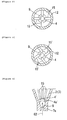
- Figure 2 is a cross-sectional view of the II-II cross section in Figure 1.
- Figure 3 is an explanatory drawing of another embodiment of the support rib.
- Figure 4 is an explanatory drawing of another embodiment of the obstructing member.
- Figure 5 is a cross-sectional view of a main part of a conventional gas-liquid separator.
- Figure 6 is a cross-sectional view of the VI-VI line in Figure 5.
- 1; gas-liquid separator, 2; case member, 3; exhaust member, 4 and 4'; obstructing member, 4a and 4a'; facing surface, 7a; lower end part, 9; liquid discharge outlet (oil discharge outlet), 12; exhaust pipe, 15 and 15'; support rib, G1 and G2; blow-by gas
- The gas-liquid separator of the present invention is a vertical type that centrifugally separates an introduced gas-liquid mixture into a gas and a liquid. The gas-
liquid separator 1 comprises acase member 2, anexhaust member 3 and an obstructingmember 4 that are described below. (Refer to Figure 1.)
The use of the gas-liquid separator is not particularly specified, but it is suitable for a device that is installed in a head cover of an internal combustion engine in a vehicle to centrifugally separate a blow-by gas into a gas and an oil. In addition, the expression "vertical type" above means that the gas-liquid separator is disposed vertically around an axial center that is vertically oriented (but that may be slightly inclined relative to a strictly vertical orientation). - The structure, shape, constituent material and the like of the case member are not particularly specified, so long as a liquid discharge outlet is formed at a lower end and is in roughly cylindrical.
An introduction inlet can be formed at an upper side of the case member for the purpose of introducing a gas-liquid mixture from a tangential direction. Additionally, the case member can consist of a cylindrical part at an upper side and a tapered part at a lower side that is continuous with the cylindrical part at upper side. Further, the material constituting to the case member may for example be a synthetic resin, a metal and the like.
The position, shape, number and the like of the liquid discharge outlet are not particularly specified. For example, the liquid discharge outlet may be opened at an outer side of the case member, but it is preferable for the liquid discharge outlet to be formed at a bottom of the case member such that it opens vertically (in the axial direction of the case member). This is so that the separated liquid can be discharged efficiently by gravity. - The structure, shape, constituent material and the like of "the exhaust member" are not particularly specified, so long as it is fixed to the upper side of the case member and has an exhaust pipe that extends vertically in the case member.
The exhaust member may have a flange part that closes off an opening part of the case member at the upper end. Additionally, the material constituting to the exhaust member may for example be a synthetic resin, a metal and the like.
A flange part for partitioning may be provided around an outer side of the exhaust pipe to partition a separated space in the case member into upper and lower sides. This flange part may suppress the unseparated gas-liquid mixture in the upper side of the separated space from flowing into the exhaust pipe. - The structure, shape, constituent material and the like of "the obstructing member" are not particularly specified, so long as it is connected to the exhaust member with a vertically extending support rib to position in the vicinity of the liquid discharge outlet. The obstructing member leads to a obstructing of a direct flow of the gas-liquid mixture from the liquid discharge outlet toward the exhaust pipe. Generally, the gas-liquid mixture which is obstructed by the obstructing member flows along the inner surface of the case member to centrifugally separate by an upper rotating flow.
The obstructing member may be one which has a surface area larger than the area of the opening in the liquid discharge outlet, and whose entire perimeter is separated from the inner surface of the case member.
The expression "in the vicinity of" above means that the obstructing member faces theliquid discharge outlet 9 by a specified gap L. (Refer to Figure 1.) It is preferable for the value of the specified gap L to be more than zero and three times or less of the diameter D1 of theliquid discharge outlet 9. - Example of the overall shape of the obstructing member includes a flat plate shape, a curved plate shape, a lump shape, an irregular shape and the like. Additionally, the plane view of the obstructing member may be circular, polygonal, irregular and the like. Moreover, a surface (an obstructing face) of the obstructing member facing toward the liquid discharge outlet may for example be a flat surface, a concave surface (a surface to be concave toward an upper side, namely a dome shape for inflow of a gas-liquid mixture) (a curved surface, a conical surface, a pyramidal surface and the like).
- The obstructing member may be one which is connected to the
exhaust pipe 12 at the lower end with thesupport rib 15 and is disposed such that it faces theliquid discharge outlet 9 formed at a bottom 7a of thecase member 2 by a specific gap L, and has a size such that it covers theliquid discharge outlet 9. (Refer to Figure 1.) - In this case, it is preferable for the support rib and the obstructing member to be arranged from an outline to the axial center of the exhaust pipe. This is so that, in the case of forming the exhaust member by die casting, the exhaust pipe and the obstructing member are used simultaneously to integral-form without requiring a complex die structure or the like.
Further, the obstructing member is preferably disposed in the vicinity of the liquid discharge outlet. - The shape, position, number and the like of the support rib are not particularly specified. The support rib may extend from the lower end of the exhaust pipe to the lower end of the support rib while inclining to the axial center of the exhaust pipe. In this case, the shape of the support rib may for example be one that extends in a roughly straight line in the vertical direction (the axial direction of the case member) (refer to Figure 2), one that extends in a helical shape that is accompanying with the rotating flow which comprises the gas-liquid mixture and occurs in the case member (refer to Figure 3), and the like. Further in the case above, the number of the support rib may be 2-6, desirably 3-5, usually 4 (refer to Figures 2 and 3). Further a taper angle of the support rib is usually smaller than an taper angle of the tapered part at the lower side, when the case member comprises the tapered part at the lower side.
Further, the number of the above support rib may be 2-6 (desirably 3-5, especially desirably 4), and the each support rib may extend from the lower end of the exhaust pipe to the lower end of the support rib while inclining to the axial center of the exhaust pipe, and the shape of the support rib may extend in a helical shape that is accompanying with the rotating flow which comprises the gas-liquid mixture and occurs in the case member, and the lower side of the case member may extend while inclining to the axial center of the case member, and the abovementioned gas-liquid mixture may be a blow-by gas. In this case, the value of the specified gap L between the exhaust member and the liquid discharge outlet may be more than zero and three times or less of the diameter D1 of the liquid discharge outlet. - The present invention will be explained in concrete below with reference to the drawings.
In the example given here, a vertical-type gas-liquid separator that is installed in a head cover of an automobile engine and that centrifugally separates a blow-by gas into a gas and an oil is exemplified. - The gas-
liquid separator 1 according to the present example comprises acase member 2, anexhaust member 3 and an obstructing plate 4 (this is an example of the obstructing member according to the present invention) as shown in Figure 1. - The
case member 2 has acylindrical part 6 at an upper side, and atapered part 7 which is disposed at a lower side and is continuous with the uppercylindrical part 6, and its overall form is roughly a cylinder that is open at the top. Thecase member 2 is made of a synthetic resin and is integral-formed by die casting. Additionally, anintroduction pipe 8 is provided on an upper and outer side of thecylindrical part 6 to introduce a blow-by gas G1 from a tangential direction. Further, an oil discharge outlet 9 (this is an example of the liquid discharge outlet according to the present invention), which has a roughly circular shape and is open in the vertical direction, is formed at the center of thelower end part 7a of thetapered part 7. - The
exhaust member 3 has aflange part 11 which closes off an opening part of thecase member 2 at the upper end, and a roughlycylindrical exhaust pipe 12 which passes vertically through theflange part 11. Theexhaust member 3 is made of a synthetic resin and is integral-formed by die casting simultaneously with the obstructing plate which is described below. Additionally, aflange part 13 for partitioning is provided around the outer side of theexhaust pipe 12 to partition a separated space S in thecase member 2 into upper and lower sides.
The upper side of thecase member 2 and theflange part 11 of theexhaust member 3 are fixed by an appropriate fixing mean such as welding, using an adhesive, a bolt or the like. - The obstructing
plate 4, as shown in Figures 1 and 2, is connected to the lower end face of theexhaust pipe 12 with a plurality of support ribs 15 (four ribs in the drawings) which extend vertically. The obstructingplate 4 is a disc that extends horizontally, and it is arranged such that it faces theoil discharge outlet 9 by a specific gap L. - In the above-mentioned example, an embodiment wherein the
support ribs 15 extend in roughly straight lines inclining from the lower end face to the axial center of theexhaust pipe 12 is exemplified. An embodiment according to the present invention is not limited to the above-mentioned configuration. The support ribs 15' may extend in a helical shape that is accompanying with the rotating flow that comprises the blow-by gas G1 and occurs in thecase member 2 as shown in Figure 3. This allows a part of the blow-by gas G1 introduced into thecase member 2 to be guided by the support ribs 15' so that a rotating flow may be smoothly formed. - Subsequently, the function of the gas-
liquid separator 1 will be explained.
The blow-by gas G1 that leaks from the combustion chamber is introduced into thecase member 2 from a tangential direction through anintroduction inlet 8a of theintroduction pipe 8, as shown in Figure 1. After that, the introduced blow-by gas G1 forms a ratating flow in thecase member 2 to centrifugally separate into a gas and an oil (oil mist). The separated oil O flows of its own weight downward along the inner surface of thecase member 2 to discharge to the outside from theoil discharge outlet 9, while the separated gas is exhausted to the outside from theexhaust pipe 12. - The blow-by gas is sometimes drawn in from both the
introduction inlet 8a and theoil discharge outlet 9 during being drawn in. In this case, the flow toward theexhaust pipe 12 of a blow-by gas G2 that is from theoil discharge outlet 9 is obstructed by a facingsurface 4a of the obstructingplate 4. And a part of the blow-by gas G2 flows toward the inner surface of thecase member 2 to centrifugally separate by an upper rotating flow. - Since the gas-
liquid separator 1 in this example comprises the obstructingplate 4 which is connected to the lower end of theexhaust pipe 12 by a plurality of thesupport ribs 15 while facing and covering theoil discharge outlet 9, the flow of the blow-by gas G2 from theoil discharge outlet 9 toward theexhaust pipe 9 may be obstructed by this obstructingplate 4 to inhibit the direct drawing of the blow-by gas G2 into theexhaust pipe 12. Thereby the separation efficiency can be improved. Additionally, since a gap that is sufficiently wide and is uniform in the circumferential direction is formed between an outer peripheral surface of the obstructingplate 4 and an inside surface of thecase member 2, the separated oil O can be smoothly discharged from theoil discharge outlet 9 via the gap. Moreover, in the case of forming theexhaust member 3 by die casting, theexhaust member 3 and the obstructingplate 4 are used simultaneously to integral-form without requiring a complex die structure or the like, being superior in machinability. - The present invention is not limited by the example above, and various modified examples that are within the scope of the claims for the present invention can be presented for purposes and uses. That is to say, the example above shows the embodiment where the obstructing
plate 4 is disc-shaped and the obstructingface 4a is flat, however, the present invention is not limited by this example. For example, a dome-shaped obstructing plate 4' having aconcave surface 4a' (a curved surface, a conical surface, a pyramidal surface and the like) as shown in Figure 4 may also be used. Theconcave surface 4a' leads to a flow of the blow-by gas G2 downward along the inner surface of thecase member 2 and the blow-by gas G2 may be efficiently separate centrifugally by an upper rotating flow. - Further, the example above also shows the embodiment where the
support ribs 15 are shaped such that each of thesupport ribs 15 extends from the lower end of the exhaust pipe to the lower end of the support rib while inclining to the axial center of the exhaust pipe, however, the present invention is not limited by this example. The support rib may be one consisting of a rib part that extends toward the center of theexhaust pipe 12 and a rib part that extends toward the axial center of theexhaust pipe 12. Moreover, the example above shows the embodiment where thesupport ribs 15 are attached to the lower end face of theexhaust pipe 12, however, the present invention is not limited by this example. Thesupport ribs 15 may be attached to an inner surface (or an outer surface) of theexhaust pipe 12 directly, for example as shown in Figures 5 and 6. - The gas-liquid separator of the present invention is widely used for many fields required in centrifugally separating a gas-liquid mixture into a gas and a liquid. In particular, the present gas-liquid separator is suitable for centrifugally separating a blow-by gas from an internal combustion engine into a gas and an oil.
Claims (10)
- A vertical-type gas-liquid separator that centrifugally separates an introduced gas-liquid mixture into a gas and a liquid, comprising:a roughly cylindrical case member in which a liquid discharge outlet is formed at a lower end,an exhaust member that is provided at an upper side of said case member and that has an exhaust pipe which extends vertically in said case member, andan obstructing member that is connected to said exhaust member with a vertically extending support rib to position in the vicinity of said liquid discharge outlet,wherein a flow of said gas-liquid mixture from said liquid discharge outlet toward said exhaust pipe is obstructed by said obstructing member.
- The gas-liquid separator according to Claim 1,
wherein said obstructing member is connected to a lower end of said exhaust pipe with said support rib,
wherein said obstructing member is disposed such that it faces said liquid discharge outlet which is formed at a bottom of said case member and is open in the vertical direction, and
wherein said obstructing member has a size such that it covers said liquid discharge outlet. - The gas-liquid separator according to Claim 2,
wherein a face of said obstructing member that faces said liquid discharge outlet is a flat surface or a concave surface. - The gas-liquid separator according to any one of Claims 1 to 3,
wherein said each support rib extends from a lower end of said exhaust pipe to a lower end of said support rib while inclining to an axial center of said exhaust pipe. - The gas-liquid separator according to any one of Claims 1 to 4,
wherein said support rib has a helical shape that is aligned to a rotating flow of said gas-liquid mixture which occurs in said case member. - The gas-liquid separator according to any one of Claims 1 to 5,
wherein said case member consists of a cylindrical part at an upper side and a tapered part at a lower side that is continuous with said cylindrical part at said upper side, and
wherein said tapered part at a lower side extends from a lower end of said cylindrical part at said upper side to a lower end of said case member while inclining to an axial center of said exhaust pipe. - The gas-liquid separator according to any one of Claims 1 to 6,
wherein a value of a specified gap L between said obstructing member and said liquid discharge outlet is more than zero and three times or less of a diameter D1 of said liquid discharge outlet. - The gas-liquid separator according to any one of Claims 1 to 7,
wherein said gas-liquid mixture is a blow-by gas. - The gas-liquid separator according to Claim 3,
wherein the number of said support rib is 2-6,
wherein said each support rib extends from a lower end of said exhaust pipe to a lower end of said support rib while inclining to an axial center of said exhaust pipe,
wherein said support rib has a helical shape that is aligned to a rotating flow of said gas-liquid mixture which occurs in said case member,
wherein said case member consists of a cylindrical part at an upper side and a tapered part at a lower side that is continuous with said cylindrical part at said upper side, and said tapered part at a lower side extends from a lower end of said cylindrical part at said upper side to a lower end of said case member while inclining to said axial center of said exhaust pipe, and
wherein said gas-liquid mixture is a blow-by gas. - The gas-liquid separator according to Claim 9,
wherein a value of a specified gap L between said obstructing member and said liquid discharge outlet is more than zero and three times or less of a diameter D1 of said liquid discharge outlet.
Applications Claiming Priority (1)
| Application Number | Priority Date | Filing Date | Title |
|---|---|---|---|
| JP2006091895A JP4535021B2 (en) | 2006-03-29 | 2006-03-29 | Gas-liquid separator |
Publications (2)
| Publication Number | Publication Date |
|---|---|
| EP1839721A1 true EP1839721A1 (en) | 2007-10-03 |
| EP1839721B1 EP1839721B1 (en) | 2010-08-04 |
Family
ID=37946179
Family Applications (1)
| Application Number | Title | Priority Date | Filing Date |
|---|---|---|---|
| EP07104142A Not-in-force EP1839721B1 (en) | 2006-03-29 | 2007-03-14 | Gas-liquid separator |
Country Status (3)
| Country | Link |
|---|---|
| EP (1) | EP1839721B1 (en) |
| JP (1) | JP4535021B2 (en) |
| DE (1) | DE602007008159D1 (en) |
Cited By (8)
| Publication number | Priority date | Publication date | Assignee | Title |
|---|---|---|---|---|
| WO2010123373A1 (en) * | 2009-04-20 | 2010-10-28 | Sorbwater Technology As | Apparatus and method for separation of phases in a multiphase flow |
| CN109550321A (en) * | 2018-12-13 | 2019-04-02 | 杭州华电能源工程有限公司 | A kind of full-automatic steam-water separator of negative-pressure type suitable for vacuum system and its application method |
| CN109578251A (en) * | 2018-12-27 | 2019-04-05 | 四川金象赛瑞化工股份有限公司 | A kind of compressor collector and method |
| CN110630454A (en) * | 2018-08-31 | 2019-12-31 | 北京金风科创风电设备有限公司 | Heat exchange devices for motors and their shafting, wind turbines |
| EP3705011A1 (en) * | 2019-03-05 | 2020-09-09 | LEONARDO S.p.A. | Centrifugal separator of gas-liquid for electrochemical battery |
| CN114570118A (en) * | 2022-05-06 | 2022-06-03 | 北京石油化工学院 | Multistage separation effect is integrated tubular vapour and liquid separator in coordination |
| WO2022135557A1 (en) * | 2020-12-25 | 2022-06-30 | 中国第一汽车股份有限公司 | Drainage device |
| CN115581944A (en) * | 2022-11-01 | 2023-01-10 | 上海至纯精密制造有限公司 | Multistage gas-liquid separator |
Families Citing this family (8)
| Publication number | Priority date | Publication date | Assignee | Title |
|---|---|---|---|---|
| JP5082762B2 (en) * | 2007-10-24 | 2012-11-28 | トヨタ紡織株式会社 | Separator |
| DE102010009722A1 (en) * | 2010-03-01 | 2011-09-01 | Hengst Gmbh & Co. Kg | Oil mist separator with at least one cyclone |
| JP5186066B2 (en) * | 2010-03-01 | 2013-04-17 | ジヤトコ株式会社 | Gas-liquid separation device for gas-liquid mixed gas |
| JP6248804B2 (en) * | 2014-05-20 | 2017-12-20 | アイシン精機株式会社 | Oil separator |
| JP6653524B2 (en) * | 2015-03-03 | 2020-02-26 | オルガノ株式会社 | Centrifugal separator and high-purity steam generator using the same |
| JP6469565B2 (en) * | 2015-12-29 | 2019-02-13 | 株式会社クボタ | engine |
| CN106246286B (en) | 2015-06-11 | 2020-05-12 | 株式会社久保田 | Engine |
| RU2755859C1 (en) * | 2020-12-28 | 2021-09-22 | Общество с ограниченной ответственностью "Экспертный технический центр ЦКБН" | Centrifugal separator |
Citations (2)
| Publication number | Priority date | Publication date | Assignee | Title |
|---|---|---|---|---|
| US2295101A (en) * | 1940-08-03 | 1942-09-08 | Socony Vacuum Oil Co Inc | Separation apparatus |
| US2846024A (en) * | 1955-05-26 | 1958-08-05 | Schweizerische Lokomotiv | Cyclone |
Family Cites Families (8)
| Publication number | Priority date | Publication date | Assignee | Title |
|---|---|---|---|---|
| US2222930A (en) * | 1939-04-14 | 1940-11-26 | Gerald D Arnold | Centrifugal separator |
| US3109723A (en) * | 1961-10-12 | 1963-11-05 | Wilkinson Chutes Inc | Water spray and cyclone type dust separator |
| JPS5189391U (en) * | 1975-01-16 | 1976-07-16 | ||
| JPS6039048Y2 (en) * | 1980-11-13 | 1985-11-22 | 東急車輌製造株式会社 | oil separator |
| JPS60144924U (en) * | 1984-03-05 | 1985-09-26 | 株式会社 大阪補機製作所 | Drain separator for air compression |
| JPH03109663U (en) * | 1990-02-21 | 1991-11-11 | ||
| JPH0893439A (en) * | 1994-09-22 | 1996-04-09 | Tokai Rubber Ind Ltd | Oil mist particle separating and growing apparatus and oil mist separating and collecting apparatus using the same |
| JP2001246216A (en) * | 1999-12-28 | 2001-09-11 | Denso Corp | Gas-liquid separation device |
-
2006
- 2006-03-29 JP JP2006091895A patent/JP4535021B2/en not_active Expired - Fee Related
-
2007
- 2007-03-14 EP EP07104142A patent/EP1839721B1/en not_active Not-in-force
- 2007-03-14 DE DE200760008159 patent/DE602007008159D1/en active Active
Patent Citations (2)
| Publication number | Priority date | Publication date | Assignee | Title |
|---|---|---|---|---|
| US2295101A (en) * | 1940-08-03 | 1942-09-08 | Socony Vacuum Oil Co Inc | Separation apparatus |
| US2846024A (en) * | 1955-05-26 | 1958-08-05 | Schweizerische Lokomotiv | Cyclone |
Cited By (16)
| Publication number | Priority date | Publication date | Assignee | Title |
|---|---|---|---|---|
| WO2010123373A1 (en) * | 2009-04-20 | 2010-10-28 | Sorbwater Technology As | Apparatus and method for separation of phases in a multiphase flow |
| CN102438758A (en) * | 2009-04-20 | 2012-05-02 | 索尔博水技术公司 | Apparatus and method for separating phases in a multiphase flow |
| US8950589B2 (en) | 2009-04-20 | 2015-02-10 | Sorbwater Technology As | Apparatus and method for separation of phases in a multiphase flow |
| US8951422B2 (en) | 2009-04-20 | 2015-02-10 | Sorbwater Technology As | Apparatus and method for separation of phases in a multiphase flow |
| CN102438758B (en) * | 2009-04-20 | 2015-05-13 | 索尔博水技术公司 | Apparatus and method for separation of phases in a multiphase flow |
| EA021685B1 (en) * | 2009-04-20 | 2015-08-31 | Сорбуотер Текнолоджи Ас | Apparatus and method for separation of phases in a multiphase flow |
| CN110630454A (en) * | 2018-08-31 | 2019-12-31 | 北京金风科创风电设备有限公司 | Heat exchange devices for motors and their shafting, wind turbines |
| CN110630454B (en) * | 2018-08-31 | 2021-03-12 | 北京金风科创风电设备有限公司 | Motor and heat exchange device of shaft system thereof and wind generating set |
| CN109550321A (en) * | 2018-12-13 | 2019-04-02 | 杭州华电能源工程有限公司 | A kind of full-automatic steam-water separator of negative-pressure type suitable for vacuum system and its application method |
| CN109578251A (en) * | 2018-12-27 | 2019-04-05 | 四川金象赛瑞化工股份有限公司 | A kind of compressor collector and method |
| EP3705011A1 (en) * | 2019-03-05 | 2020-09-09 | LEONARDO S.p.A. | Centrifugal separator of gas-liquid for electrochemical battery |
| US11135601B2 (en) | 2019-03-05 | 2021-10-05 | Leonardo S.P.A. | Centrifugal separator of gas—liquid for electrochemical battery |
| WO2022135557A1 (en) * | 2020-12-25 | 2022-06-30 | 中国第一汽车股份有限公司 | Drainage device |
| CN114570118A (en) * | 2022-05-06 | 2022-06-03 | 北京石油化工学院 | Multistage separation effect is integrated tubular vapour and liquid separator in coordination |
| CN114570118B (en) * | 2022-05-06 | 2022-07-26 | 北京石油化工学院 | A tubular gas-liquid separator with synergistic integration of multi-stage and multi-stage separation |
| CN115581944A (en) * | 2022-11-01 | 2023-01-10 | 上海至纯精密制造有限公司 | Multistage gas-liquid separator |
Also Published As
| Publication number | Publication date |
|---|---|
| JP2007263066A (en) | 2007-10-11 |
| JP4535021B2 (en) | 2010-09-01 |
| DE602007008159D1 (en) | 2010-09-16 |
| EP1839721B1 (en) | 2010-08-04 |
Similar Documents
| Publication | Publication Date | Title |
|---|---|---|
| EP1839721B1 (en) | Gas-liquid separator | |
| US7655078B2 (en) | Bubble separator | |
| US7850754B2 (en) | Device for separating a gas-liquid mixture, in particular during ventilation of a crankcase of an internal combustion engine | |
| EP1887192B1 (en) | Vapor-liquid separator | |
| US20080179227A1 (en) | Bubble separator | |
| US20010005986A1 (en) | Cyclone type gas-liquid separator | |
| EP3050631B1 (en) | Rotating secondary divider | |
| CN104364479B (en) | Lid assembly for covering cylinder head and application thereof | |
| JPH055579A (en) | Gas/liquid separator | |
| US20090229585A1 (en) | Oil separator for blow-by gas | |
| JP2008267582A (en) | Breather equipment | |
| EP2868878B1 (en) | Oil separator | |
| JP4063179B2 (en) | Oil separator | |
| EP4112153B1 (en) | Gas-liquid separator | |
| JPH0425212Y2 (en) | ||
| JP2018100608A (en) | Oil separator | |
| EP0487203A2 (en) | Oil filter having gas separator | |
| JPH08158853A (en) | Separator of oil in blow-by gas | |
| JPH0310336Y2 (en) | ||
| RU2659988C1 (en) | Gas-dynamic vortex separator (options) | |
| CN211924419U (en) | Built-in vertical oil separator for compressor | |
| JP2009221858A (en) | Oil separator for blow-by gas | |
| JP5034357B2 (en) | Gas-liquid separator | |
| JP2002340289A (en) | Gas-liquid separator having drain valve | |
| JP2019190325A (en) | Oil separator |
Legal Events
| Date | Code | Title | Description |
|---|---|---|---|
| PUAI | Public reference made under article 153(3) epc to a published international application that has entered the european phase |
Free format text: ORIGINAL CODE: 0009012 |
|
| 17P | Request for examination filed |
Effective date: 20070314 |
|
| AK | Designated contracting states |
Kind code of ref document: A1 Designated state(s): AT BE BG CH CY CZ DE DK EE ES FI FR GB GR HU IE IS IT LI LT LU LV MC MT NL PL PT RO SE SI SK TR |
|
| AX | Request for extension of the european patent |
Extension state: AL BA HR MK YU |
|
| 17Q | First examination report despatched |
Effective date: 20080328 |
|
| AKX | Designation fees paid |
Designated state(s): DE FR GB |
|
| GRAP | Despatch of communication of intention to grant a patent |
Free format text: ORIGINAL CODE: EPIDOSNIGR1 |
|
| GRAS | Grant fee paid |
Free format text: ORIGINAL CODE: EPIDOSNIGR3 |
|
| GRAA | (expected) grant |
Free format text: ORIGINAL CODE: 0009210 |
|
| AK | Designated contracting states |
Kind code of ref document: B1 Designated state(s): DE FR GB |
|
| REG | Reference to a national code |
Ref country code: GB Ref legal event code: FG4D |
|
| REF | Corresponds to: |
Ref document number: 602007008159 Country of ref document: DE Date of ref document: 20100916 Kind code of ref document: P |
|
| PLBE | No opposition filed within time limit |
Free format text: ORIGINAL CODE: 0009261 |
|
| STAA | Information on the status of an ep patent application or granted ep patent |
Free format text: STATUS: NO OPPOSITION FILED WITHIN TIME LIMIT |
|
| 26N | No opposition filed |
Effective date: 20110506 |
|
| REG | Reference to a national code |
Ref country code: DE Ref legal event code: R097 Ref document number: 602007008159 Country of ref document: DE Effective date: 20110506 |
|
| GBPC | Gb: european patent ceased through non-payment of renewal fee |
Effective date: 20110314 |
|
| REG | Reference to a national code |
Ref country code: FR Ref legal event code: ST Effective date: 20111130 |
|
| PG25 | Lapsed in a contracting state [announced via postgrant information from national office to epo] |
Ref country code: FR Free format text: LAPSE BECAUSE OF NON-PAYMENT OF DUE FEES Effective date: 20110331 |
|
| PG25 | Lapsed in a contracting state [announced via postgrant information from national office to epo] |
Ref country code: GB Free format text: LAPSE BECAUSE OF NON-PAYMENT OF DUE FEES Effective date: 20110314 |
|
| PGFP | Annual fee paid to national office [announced via postgrant information from national office to epo] |
Ref country code: DE Payment date: 20170307 Year of fee payment: 11 |
|
| REG | Reference to a national code |
Ref country code: DE Ref legal event code: R119 Ref document number: 602007008159 Country of ref document: DE |
|
| PG25 | Lapsed in a contracting state [announced via postgrant information from national office to epo] |
Ref country code: DE Free format text: LAPSE BECAUSE OF NON-PAYMENT OF DUE FEES Effective date: 20181002 |