EP1838995B1 - Method for heating an industrial furnace, and apparatus suitable for carrying out the method - Google Patents
Method for heating an industrial furnace, and apparatus suitable for carrying out the method Download PDFInfo
- Publication number
- EP1838995B1 EP1838995B1 EP06701188A EP06701188A EP1838995B1 EP 1838995 B1 EP1838995 B1 EP 1838995B1 EP 06701188 A EP06701188 A EP 06701188A EP 06701188 A EP06701188 A EP 06701188A EP 1838995 B1 EP1838995 B1 EP 1838995B1
- Authority
- EP
- European Patent Office
- Prior art keywords
- membrane
- reactant
- volumetric flow
- burner
- course
- Prior art date
- Legal status (The legal status is an assumption and is not a legal conclusion. Google has not performed a legal analysis and makes no representation as to the accuracy of the status listed.)
- Expired - Lifetime
Links
Images


Classifications
-
- F—MECHANICAL ENGINEERING; LIGHTING; HEATING; WEAPONS; BLASTING
- F23—COMBUSTION APPARATUS; COMBUSTION PROCESSES
- F23C—METHODS OR APPARATUS FOR COMBUSTION USING FLUID FUEL OR SOLID FUEL SUSPENDED IN A CARRIER GAS OR AIR
- F23C7/00—Combustion apparatus characterised by arrangements for air supply
- F23C7/008—Flow control devices
-
- F—MECHANICAL ENGINEERING; LIGHTING; HEATING; WEAPONS; BLASTING
- F23—COMBUSTION APPARATUS; COMBUSTION PROCESSES
- F23K—FEEDING FUEL TO COMBUSTION APPARATUS
- F23K2900/00—Special features of, or arrangements for fuel supplies
- F23K2900/05003—Non-continuous fluid fuel supply
Definitions
- the present invention relates to a method for heating an industrial furnace by pulsating combustion, in which gaseous or liquid reactants, comprising an oxidizing agent and fuel, are fed to a burner, the volumetric flow of at least one of the reactants which emerges from the burner mouth being changed over the course of time.
- the invention relates to an apparatus for heating an industrial furnace by pulsating combustion, having a burner, which includes feed lines for streams of gaseous or liquid reactants leading to a burner mouth, and having a device for varying the volumetric flow of at least one of the reactants over the course of time.
- both the oxygen and the fuel may contain small quantities of nitrogen. These small quantities of nitrogen, in combination with the combustion using oxygen being hotter than combustion using air, at around 900°C, lead to an increased level of NOx in the off-gas.
- DE 692 16 317 T2 which has disclosed a method and an apparatus of the generic type described in the introduction, to cyclically vary either the quantitative flows of the fuel or those of the oxidizing agent using a solenoid valve which is arranged in the respective feed line, at a frequency of below 3 Hz.
- a solenoid valve which is arranged in the respective feed line, at a frequency of below 3 Hz.
- SU 857 642 proposes that the gas stream be periodically interrupted with the aid of a rotor.
- the invention is based on the object of providing a method which allows a simple and flexible change to the flow during pulsating combustion.
- the invention is based on the object of providing a low-maintenance apparatus of simple design which is suitable for carrying out the method.
- the volumetric flow of at least one of the reactants involved in the combustion reaction - i.e. the fuel gas or the oxidizing agent - is varied over the course of time by causing at least one membrane to deflect.
- the membrane is arranged in a membrane space which is fluid-connected to the feed of the respective reactant to the burner and is therefore accessible to the reactant.
- the membrane space allows the membrane arranged in it to be deflected as far as possible without obstacle.
- the membrane space and the membrane arranged in it are also referred to below as a "membrane module".
- the membrane In the membrane space, the membrane is deflected by electrical actuation in the presence of the reactant in question, and in this way the electrical power is converted into changes in volume - associated with changes in pressure - in the membrane space, as is generally known for loudspeakers.
- the changes in volume of the membrane space are determined by frequency, amplitude and profile of the change in the volumetric flow of the reactant at the burner mouth over the course of time. Therefore, the method, by virtue of the electrically excited deflection of the membrane, allows the flow of the reactant to be changed without this requiring any moving or rotating components, apart from the membrane.
- the membrane itself is subject to very little wear, and consequently a long service life and long maintenance intervals can be achieved.
- the change in the volumetric flow of the reactant(s), in addition to the on and off states may also encompass any desired intermediate values for the maximum amplitude or a predetermined volumetric flow profile over the course of time, such as for example a square-wave, sawtooth, sinusoidal or trapezoidal profile.
- Equipping the supply lines for both the fuel and the oxidizing agent with membrane modules of this type also makes it readily possible to vary the volumetric flow of both reactants, for example independently of one another over the course of time or as a function of one another over the course of time, for example in-phase, in opposite phase or in phase-shifted fashion.
- the method allows a preset time profile, for example a square-wave profile, to be accurately maintained without significant dead times or slippages.
- the change in the volume of the gas stream of the relevant reactant or reactants over the course of time can be set and controlled in a particularly simple way by means of the control unit.
- Predetermined deflection cycles can be passed through under programme control and are easy to adapt of necessary.
- the restricting device prevents or reduces a back-flow of the reactant. This measure ensures that the changes in volume produced in the membrane space act in the direction of the burner mouth and not, or to a lesser extent, "towards the rear" in the direction of the source of the reactant in question. This effect of the restricting device becomes more effective the closer to the membrane space it occurs.
- Valves, flaps, throttles or diaphragms can be used as the restricting device.
- moving mechanical components should as far as possible be avoided, and consequently it is preferable for the restricting device to be designed as a throttle or diaphragm.
- the throttle or diaphragm is in this case installed in the feed line, as close as possible to the entry to the membrane space. This results in a pressure drop in the direction of the membrane space, which prevents a back-flow of the reactant and promotes an effective change in the volume in the direction of the burner mouth. This measure converts the change in the volume of the membrane space into a change in the flow or velocity of the reactant at the burner mouth without attenuation and in a simple, rapid and particularly effective way without the need for moving parts.
- the method allows a constant volumetric flow of the reactant upstream of the restricting device.
- a minimum level for the volumetric flow of the reactant, which the volumetric flow does not drop below at any time even when the volumetric flow is changing, is predetermined.
- a base load is predetermined as a partial quantity of the total volumetric flow of the corresponding reactant, and the volumetric flow does not drop below this partial quantity at any time even during a change in the volumetric flow. In the simplest case, this is achieved by a bypass parallel to the membrane space.
- the membrane spaces of the two burners it has proven particularly advantageous for the membrane spaces of the two burners to be arranged adjacent to one another and to be separated from one another by a common membrane.
- the membrane spaces of the two burners share one membrane, the volumetric flows of the reactant can be changed in opposite phase without the need for a separate control device.
- the membrane divides the membrane spaces on both sides, so that even in the event of a defect in the membrane, there is no leakage into the environment, but rather it is only the pulsating combustion which is disrupted. This improves the operational reliability of the apparatus.
- the volumetric flow of the oxidizing agent it is preferable for the volumetric flow of the oxidizing agent to be kept constant.
- the apparatus comprises a membrane, which can be deflected and is mounted such that it can oscillate, and an electrical actuation, which can be used to mechanically deflect the membrane.
- the change in the volumetric flow of at least one of the reactants involved in the combustion reaction - i.e. the fuel gas and/or the oxidizing agent - is brought about by means of the membrane deflection.
- the membrane and the excitation means are correspondingly made to match the designs which are standard in loudspeaker construction. In this respect, reference is made to the explanations given above in connection with the method.
- the apparatus by electrically exciting the membrane, allows virtually any desired, predetermined change in the volumetric flow of the reactant over the course of time without requiring any moving parts, apart from the membrane.
- the membrane itself is subject to very little wear, and consequently a long service life and long apparatus maintenance intervals can be achieved.
- the change in the volumetric flow of the reactant(s) may also include any desired intermediate values between zero and the maximum amplitude or a predetermined volumetric flow profile over the course of time, such as for example a square-wave, sawtooth, sinusoidal or trapezoidal volumetric flow profile. It is also possible for the volumetric flows of fuel and oxidizing agent to be varied independently of one another by equipping the supply lines for both fuel and oxidizing agent with membrane modules of this type; by way of example, these volumetric flows can be varied in-phase, in opposite phase or in phase-shifted fashion.
- FIG. 1 diagrammatically depicts a glass melting tank 1 with a plurality of structurally identical natural gas/oxygen burners 3, 3a, 3b, 3c, which are mounted in pairs offset with respect to one another, pointing into the furnace space 18, on the opposite side walls 2 of the tank 1.
- the burners 3, 3a, 3b, 3c are simple tube-in-tube burners with an inner tube 4 for supplying fuel, which is coaxially surrounded by an outer tube 6, forming an annular gap 5 for oxygen to pass through.
- the reactants which emerge from the burner mouth 7 react with one another to form a burner flame 8.
- the feed connection pieces for natural gas and oxygen are denoted by reference numerals 9 and 10.
- membrane modules 11 and 12 are arranged between the burner and the feed lines 9 for natural gas and 10 for oxygen, respectively.
- membrane modules in each case comprise a membrane space 13, in which two electrodynamic loudspeakers each having a membrane 14 are mounted opposite one another.
- the membranes 14 each comprise a gastight, stretchable material and deflections are imparted to them in phase by means of an electromagnet 15. That side of the membrane 14 which is remote from the membrane space 13 is located in the open atmosphere.
- the parameters for the change in volume inside the membrane space 13, such as frequency, amplitude or phase shift between the two reactants of the same burner 3 or another of the burners 3a, 3b, 3c are predetermined by one control module 16 for both membrane modules 11 and 12.
- a diaphragm 17 is fitted in the feed line 9, 10 immediately upstream of the respective membrane space 13.
- Each of the burners 3, 3a, 3b, 3c is designed for heating power of 200 kW.
- 20 m 3 /h of natural gas (CH 4 ) and 40 m 3 /h of oxygen are fed in.
- the change in the volumetric flow of the natural gas emerging at the burner mouth 7 by means of the membrane module 11 is effected by deflections being imposed on the membrane 14 by means of the control module 16, which deflections cause a volumetric flow which changes over the course of time with a frequency of, for example, 1 Hz.
- the time profile of the volumetric change produced in this way has a precise square-wave profile.
- the changes in volume cause changes in through-flow, which continue via the membrane space 13 into the inner tube 4 as far as the burner mouth 7 and as a result cause a variable flow velocity of the natural gas at the burner mouth 7.
- the size and displacement of the membrane 14 and the volume of the membrane space 13 are designed in such a way that the natural-gas volumetric flow of 40 m 3 /h can be completely switched on and off at a frequency of 1 Hz, so that a mean volumetric flow of 20 m 3 /h (s.t.p.) results.
- the diaphragm 17 prevents the natural gas from flowing back into the natural-gas feed line 9 and in this way ensures that the change in volume generated by the membrane 14 acts entirely as a change in the volumetric flow of natural gas at the burner mouth 7.
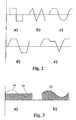
- the profile of the deliberately altered volumetric flow of natural gas over the course of time ideally has a square-wave profile, as is diagrammatically depicted in Figure 2a ).
- the membrane modules 11 of a pair of burners in each case operate in opposite phase.
- the pressure profile at the burner 3 (and at the burner 3a) is in opposite phase to the pressure profile at the burner 3c (and at the burner 3b).
- pulsating combustion of this type reduces the NOx emission level by 30%, without any adverse effect on the radiation properties of the flame.
- Figures 2 to 5 diagrammatically depict further suitable procedures for pulsating combustion.
- Figure 2 shows a square-wave (a), sawtooth (b), sinusoidal (c), trapezoidal (d) and a freely selectable or random (e) change in volumetric flow. All the through-flows illustrated are in the positive range, i.e. the volumetric flow which results is at all times higher than a predetermined minimum base load.
- Figure 4a shows a suitable volumetric flow profile over the course of time for the situation in which both the natural-gas flow and the oxygen flow are varied.
- the change 41 in the volumetric flow of the oxygen has double the frequency and amplitude of the change 42 in volumetric flow of the natural gas.
- Figure 4b diagrammatically depicts a method variant in which the oxygen flow is kept constant over the course of time.
- the control unit 16 can also easily be used to generate changes in volumetric flow which do not have a fixed, recurring period.
- the embodiment of a membrane module 60 which is illustrated in Figure 6 is suitable in particular for operation with opposite-phase supply of a reactant to two separate burners (not shown in the drawing).
- the two burners in this case divide the membrane module 60.
- the membrane 61 divides the two membrane spaces 62 and 63, which are of equal size.
- the electromagnet 64 is provided in the membrane space 62.
- the gas inlet and gas outlet of the membrane space 62 for one burner are indicated by connection pieces 65, and the gas inlet and gas outlet of the membrane space 63 for the other burner are denoted by connection pieces 66.
- the two maximum deflections of the membrane 61 into the respective membrane spaces 62 and 63 are represented by dashed lines 67.
- the reduction in volume caused by the deflection into one membrane space 62 produces an increase in volume of the same magnitude and at the same time in the other membrane space 63. This therefore ensures that the volumetric flows for the natural gas to the two burners alter precisely in opposite phase.
- the deflection in the membrane is associated with an increase and reduction in the volume of the membrane space.
- the changes in volume effect mass transfer without producing a soundwave.
- the method according to the invention is not restricted to this particular application. It is also possible, using a moving membrane, to generate pressure waves - without mass transfer - which allow pulsating combustion. In this case, the deflection direction of the membrane corresponds to the main direction of propagation of the burner flame.
Landscapes
- Engineering & Computer Science (AREA)
- Chemical & Material Sciences (AREA)
- Combustion & Propulsion (AREA)
- Mechanical Engineering (AREA)
- General Engineering & Computer Science (AREA)
- Feeding And Controlling Fuel (AREA)
- Fluidized-Bed Combustion And Resonant Combustion (AREA)
- Oxygen, Ozone, And Oxides In General (AREA)
- Vending Machines For Individual Products (AREA)
- Heat Treatment Of Articles (AREA)
Abstract
Description
- The present invention relates to a method for heating an industrial furnace by pulsating combustion, in which gaseous or liquid reactants, comprising an oxidizing agent and fuel, are fed to a burner, the volumetric flow of at least one of the reactants which emerges from the burner mouth being changed over the course of time.
- Furthermore, the invention relates to an apparatus for heating an industrial furnace by pulsating combustion, having a burner, which includes feed lines for streams of gaseous or liquid reactants leading to a burner mouth, and having a device for varying the volumetric flow of at least one of the reactants over the course of time.
- It is generally known to use fuel/oxygen burners in industrial furnaces for heating metal or glass melts. Compared to melting methods in which the oxidizing agent used is air, the use of oxygen increases the melting power of the furnace and reduces the energy consumption. The fuel saving is mainly based on the fact that the nitrogen content of the air does not have to be heated. The smaller quantities of off-gas which result reduce the overall size of off-gas purification installations.
- The overall quantity of NOx can be reduced considerably by the use of pure oxygen and fuel without any nitrogen. However, in industrial application, both the oxygen and the fuel may contain small quantities of nitrogen. These small quantities of nitrogen, in combination with the combustion using oxygen being hotter than combustion using air, at around 900°C, lead to an increased level of NOx in the off-gas.
- To avoid this, it is proposed in
DE 692 16 317 T2 , which has disclosed a method and an apparatus of the generic type described in the introduction, to cyclically vary either the quantitative flows of the fuel or those of the oxidizing agent using a solenoid valve which is arranged in the respective feed line, at a frequency of below 3 Hz. A similar concept using a solenoid valve is to be found inDE 693 02 060 T2 .SU 857 642 - Further processes and apparatuses for pulsed combustion are disclosed in
US 5 302 111 andUS 5 522 721 , wherby the pulsation of the gases fed to burners is realised by mechanical means, e.g. electro valves or rotary valves. - The known procedures require the use of mechanical, moving components, such as valves, control flaps, rotors or the like, and complex measurement and control technology to effect the pulsating combustion. An additional factor is that the previous solutions are somewhat inflexible with regard to changing the frequency or amplitude of the pulsation. For example, control by means of solenoid valves only allows on and off states but does not permit any intermediate states. It is also only possible to change the pulsation frequency to a limited extent, for example depending on the switching speed of the solenoid valves. Furthermore, the service life of solenoid valves is restricted to approximately 10 000 000 switching operations, which at a switching frequency of, for example, 1 Hz corresponds to a service life of approximately 6 months, which in practice leads to short maintenance intervals which are barely acceptable.
- Therefore, the invention is based on the object of providing a method which allows a simple and flexible change to the flow during pulsating combustion.
- Furthermore, the invention is based on the object of providing a low-maintenance apparatus of simple design which is suitable for carrying out the method.
- With regard to the method, this object is achieved, by a method according to
claim 1. - In the method the volumetric flow of at least one of the reactants involved in the combustion reaction - i.e. the fuel gas or the oxidizing agent - is varied over the course of time by causing at least one membrane to deflect. The membrane is arranged in a membrane space which is fluid-connected to the feed of the respective reactant to the burner and is therefore accessible to the reactant. The membrane space allows the membrane arranged in it to be deflected as far as possible without obstacle. The membrane space and the membrane arranged in it are also referred to below as a "membrane module".
- In the membrane space, the membrane is deflected by electrical actuation in the presence of the reactant in question, and in this way the electrical power is converted into changes in volume - associated with changes in pressure - in the membrane space, as is generally known for loudspeakers.
- The constructions and principles of operation which are known for loudspeaker construction, involving a vibrating membrane and excitation means, are fundamentally also suitable for generating the change in volume in the flow of reactant in the context of the method. Examples which may be mentioned include electrodynamic loudspeakers, electrostatic loudspeakers, ferroelectric loudspeakers, magnetic loudspeakers or ultrasonic loudspeakers. Designs without a mechanical membrane, as used for ion or plasma loudspeakers, in which the surrounding atmosphere is excited by modulated high voltage, so that the resulting local ionization causes thermal expansion and therefore sound pressure, are in principle also suitable for carrying out the method.
- The changes in volume of the membrane space are determined by frequency, amplitude and profile of the change in the volumetric flow of the reactant at the burner mouth over the course of time. Therefore, the method, by virtue of the electrically excited deflection of the membrane, allows the flow of the reactant to be changed without this requiring any moving or rotating components, apart from the membrane. The membrane itself is subject to very little wear, and consequently a long service life and long maintenance intervals can be achieved.
- Furthermore, the change in the volumetric flow of the reactant(s), in addition to the on and off states, may also encompass any desired intermediate values for the maximum amplitude or a predetermined volumetric flow profile over the course of time, such as for example a square-wave, sawtooth, sinusoidal or trapezoidal profile. Equipping the supply lines for both the fuel and the oxidizing agent with membrane modules of this type also makes it readily possible to vary the volumetric flow of both reactants, for example independently of one another over the course of time or as a function of one another over the course of time, for example in-phase, in opposite phase or in phase-shifted fashion. The method allows a preset time profile, for example a square-wave profile, to be accurately maintained without significant dead times or slippages.
- The additional design outlay required for this type of configuration of a burner is only slight; it is even possible for an existing burner to be retrofitted without major outlay, in which case a corresponding membrane module with actuation is incorporated into the existing feed line.
- It has proven particularly appropriate for the electrical actuation to be effected by means of an electromagnet, by the latter acting on the membrane or on a ferromagnetic body connected to the membrane.
- This is a simple design principle for the membrane module, as is known, for example, for conventional ferroelectric loudspeakers. The amplitude and frequency of the membrane oscillation are in this case predetermined by electrical pulses of the electromagnet. Membrane modules of this type are distinguished by being robust and operationally reliable.
- It is advantageous for the electrical actuation of the membrane to comprise a control unit.
- The change in the volume of the gas stream of the relevant reactant or reactants over the course of time can be set and controlled in a particularly simple way by means of the control unit. Predetermined deflection cycles can be passed through under programme control and are easy to adapt of necessary.
- It has proven particularly favourable for the back-flow of the reactant out of the membrane space to be avoided or reduced by means of a restricting device provided in the reactant feed.
- The restricting device prevents or reduces a back-flow of the reactant. This measure ensures that the changes in volume produced in the membrane space act in the direction of the burner mouth and not, or to a lesser extent, "towards the rear" in the direction of the source of the reactant in question. This effect of the restricting device becomes more effective the closer to the membrane space it occurs.
- Valves, flaps, throttles or diaphragms can be used as the restricting device. However, moving mechanical components should as far as possible be avoided, and consequently it is preferable for the restricting device to be designed as a throttle or diaphragm.
- The throttle or diaphragm is in this case installed in the feed line, as close as possible to the entry to the membrane space. This results in a pressure drop in the direction of the membrane space, which prevents a back-flow of the reactant and promotes an effective change in the volume in the direction of the burner mouth. This measure converts the change in the volume of the membrane space into a change in the flow or velocity of the reactant at the burner mouth without attenuation and in a simple, rapid and particularly effective way without the need for moving parts.
- The method allows a constant volumetric flow of the reactant upstream of the restricting device.
- It is not the volumetric flow of the reactant upstream of the restricting device which is varied over the course of time, but rather a change in volume is imposed on the flow, which has been constant up to that point, purely by the movement of the membrane, resulting in a change in the velocity at which the reactant flows out at the burner mouth over the course of time. A constant volumetric flow as far as the restricting device is simple to implement; it is therefore possible to dispense with mechanical components or change in the volumetric flow, such as valves or the like.
- In a particularly preferred method variant, a minimum level for the volumetric flow of the reactant, which the volumetric flow does not drop below at any time even when the volumetric flow is changing, is predetermined.
- In this case, a base load is predetermined as a partial quantity of the total volumetric flow of the corresponding reactant, and the volumetric flow does not drop below this partial quantity at any time even during a change in the volumetric flow. In the simplest case, this is achieved by a bypass parallel to the membrane space.
- On account of the variation in the volumetric flow of the reactants or a reactant over the course of time, pressure fluctuations may occur in the furnace space, which can lead to the ingress of external air and therefore accordingly to a rise in the emission of NOx. This is prevented if the load level does not drop below the predetermined base load of the reactant or if - ideally - a pressure drop in the furnace space is avoided.
- In this respect, it has proven particularly appropriate if at least two burners are provided for heating the industrial furnace, with the volumetric flow of the reactant to one burner being changed in the opposite phase to the volumetric flow of the reactant to the other burner.
- As a result of the volumetric flow to the two burners, which may; for example, be arranged opposite and offset with respect to one another in the furnace space, being changed in opposite phase, an approximately constant pressure is always maintained in the furnace space, so that there is no risk of the admission of external air. This effect can be achieved even if the volumetric flows of a plurality of pairs of burners change in opposite phase.
- In this context, it has proven particularly advantageous for the membrane spaces of the two burners to be arranged adjacent to one another and to be separated from one another by a common membrane.
- On account of the fact that the membrane spaces of the two burners share one membrane, the volumetric flows of the reactant can be changed in opposite phase without the need for a separate control device. The membrane divides the membrane spaces on both sides, so that even in the event of a defect in the membrane, there is no leakage into the environment, but rather it is only the pulsating combustion which is disrupted. This improves the operational reliability of the apparatus.
- It has proven particularly expedient for the volumetric flow of the fuel at the burner mouth to be changed.
- In this case, it is preferable for the volumetric flow of the oxidizing agent to be kept constant.
- With regard to the apparatus, the object referred to above is achieved, by an apparatus according to
claim 11. - The apparatus comprises a membrane, which can be deflected and is mounted such that it can oscillate, and an electrical actuation, which can be used to mechanically deflect the membrane. The change in the volumetric flow of at least one of the reactants involved in the combustion reaction - i.e. the fuel gas and/or the oxidizing agent - is brought about by means of the membrane deflection. For this purpose, there is a membrane space which is accessible to the reactant in question and in the simplest case is arranged in the feed line for the respective reactant in the vicinity of the burner mouth.
- The membrane and the excitation means are correspondingly made to match the designs which are standard in loudspeaker construction. In this respect, reference is made to the explanations given above in connection with the method.
- The apparatus by electrically exciting the membrane, allows virtually any desired, predetermined change in the volumetric flow of the reactant over the course of time without requiring any moving parts, apart from the membrane. The membrane itself is subject to very little wear, and consequently a long service life and long apparatus maintenance intervals can be achieved.
- Furthermore, in addition to the on and off states, the change in the volumetric flow of the reactant(s) may also include any desired intermediate values between zero and the maximum amplitude or a predetermined volumetric flow profile over the course of time, such as for example a square-wave, sawtooth, sinusoidal or trapezoidal volumetric flow profile. It is also possible for the volumetric flows of fuel and oxidizing agent to be varied independently of one another by equipping the supply lines for both fuel and oxidizing agent with membrane modules of this type; by way of example, these volumetric flows can be varied in-phase, in opposite phase or in phase-shifted fashion.
- The outlay involved in providing a burner with this equipment is low, and even retrofitting an existing burner by incorporating a suitable membrane module in combination with an electrical actuation into the existing gas line does not require major structural outlay.
- Advantageous configurations of the apparatus will emerge from the subclaims. Where configurations of the apparatus mentioned in the subclaims correspond to the method procedures described in subclaims relating to the method, reference is made, for additional explanation, to the statements given above in connection with the corresponding method claims.
- The invention is described in more detail below on the basis of exemplary embodiments and a patent drawing, in which, in detail:
- Figure 1
- shows a glass melting tank with a plurality of burners mounted in the side wall for pulsating combustion, in the form of a diagrammatically depicted plan view,
- Figure 2
- shows various changes in volumetric flows of a reactant over the course of time for pulsating combustion,
- Figure 3
- superimposes a variable volumetric flow on a constant base load,
- Figure 4
- shows various changes in the volumetric flows of fuel and oxidizing agent over the course of time,
- Figure 5
- shows a phase-shifted change in volumetric flows between fuel and oxidizing agent, and
- Figure 6
- shows a further embodiment of a membrane module for operating with opposite-phase change in the volumetric flow of a reactant to two burners.
- The plan view represented in
Figure 1 diagrammatically depicts aglass melting tank 1 with a plurality of structurally identical natural gas/oxygen burners furnace space 18, on theopposite side walls 2 of thetank 1. - The
burners inner tube 4 for supplying fuel, which is coaxially surrounded by anouter tube 6, forming anannular gap 5 for oxygen to pass through. The reactants which emerge from theburner mouth 7 react with one another to form aburner flame 8. The feed connection pieces for natural gas and oxygen are denoted byreference numerals 9 and 10. - To generate pulsating combustion, a change in volume is imparted to one or both gas streams (oxygen and natural gas). For this purpose,
membrane modules - These membrane modules in each case comprise a
membrane space 13, in which two electrodynamic loudspeakers each having amembrane 14 are mounted opposite one another. Themembranes 14 each comprise a gastight, stretchable material and deflections are imparted to them in phase by means of anelectromagnet 15. That side of themembrane 14 which is remote from themembrane space 13 is located in the open atmosphere. - The parameters for the change in volume inside the
membrane space 13, such as frequency, amplitude or phase shift between the two reactants of thesame burner 3 or another of theburners control module 16 for bothmembrane modules diaphragm 17 is fitted in thefeed line 9, 10 immediately upstream of therespective membrane space 13. - The text which follows provides a more detailed explanation of the method according to the invention by way of example with reference to the tube-in-
tube burner 3 in theglass melting tank 1 which is diagrammatically depicted inFigure 1 . - Each of the
burners - The change in the volumetric flow of the natural gas emerging at the
burner mouth 7 by means of themembrane module 11 is effected by deflections being imposed on themembrane 14 by means of thecontrol module 16, which deflections cause a volumetric flow which changes over the course of time with a frequency of, for example, 1 Hz. The time profile of the volumetric change produced in this way has a precise square-wave profile. The changes in volume cause changes in through-flow, which continue via themembrane space 13 into theinner tube 4 as far as theburner mouth 7 and as a result cause a variable flow velocity of the natural gas at theburner mouth 7. - The size and displacement of the
membrane 14 and the volume of themembrane space 13 are designed in such a way that the natural-gas volumetric flow of 40 m3/h can be completely switched on and off at a frequency of 1 Hz, so that a mean volumetric flow of 20 m3/h (s.t.p.) results. Thediaphragm 17 prevents the natural gas from flowing back into the natural-gas feed line 9 and in this way ensures that the change in volume generated by themembrane 14 acts entirely as a change in the volumetric flow of natural gas at theburner mouth 7. - The profile of the deliberately altered volumetric flow of natural gas over the course of time ideally has a square-wave profile, as is diagrammatically depicted in
Figure 2a ). - To minimize pressure fluctuations within the
glass melting tank 1 and the ingress of external air, themembrane modules 11 of a pair of burners in each case operate in opposite phase. The pressure profile at the burner 3 (and at the burner 3a) is in opposite phase to the pressure profile at theburner 3c (and at theburner 3b). Compared to normal operation, pulsating combustion of this type reduces the NOx emission level by 30%, without any adverse effect on the radiation properties of the flame. A similar effect results if the membrane modules of twoadjacent burners 3, 3a are in opposite phase.Figures 2 to 5 diagrammatically depict further suitable procedures for pulsating combustion. -
Figure 2 shows a square-wave (a), sawtooth (b), sinusoidal (c), trapezoidal (d) and a freely selectable or random (e) change in volumetric flow. All the through-flows illustrated are in the positive range, i.e. the volumetric flow which results is at all times higher than a predetermined minimum base load. - The change in volumetric flow shown in
Figure 3 a provides for a constant proportion of the gas flow (base load 31), on which a further, deliberately changed proportion of thegas flow 32 is superimposed. The resultant volumetric flow 33 (Figure 3b ) never adopts a negative value, since this would lead to undesirable flashbacks. For safety reasons, the minimum volumetric flow which results must always be positive and must not drop below a defined level. - As a result of the supply lines of both the natural gas and the oxygen being equipped with
membrane modules -
Figure 4a ) shows a suitable volumetric flow profile over the course of time for the situation in which both the natural-gas flow and the oxygen flow are varied. In the exemplary embodiment, thechange 41 in the volumetric flow of the oxygen has double the frequency and amplitude of thechange 42 in volumetric flow of the natural gas.Figure 4b ) diagrammatically depicts a method variant in which the oxygen flow is kept constant over the course of time. - In the illustration presented in
Figure 5a ), the changes in volumetric flow ofoxygen 51 andnatural gas 52 over the course of time are in phase and only the amplitudes differ. In the illustration presented inFigure 5b ), the modulation profiles foroxygen 51 andnatural gas 52 are phase-shifted. - The
control unit 16 can also easily be used to generate changes in volumetric flow which do not have a fixed, recurring period. - The embodiment of a
membrane module 60 which is illustrated inFigure 6 is suitable in particular for operation with opposite-phase supply of a reactant to two separate burners (not shown in the drawing). The two burners in this case divide themembrane module 60. Themembrane 61 divides the twomembrane spaces electromagnet 64 is provided in themembrane space 62. The gas inlet and gas outlet of themembrane space 62 for one burner are indicated byconnection pieces 65, and the gas inlet and gas outlet of themembrane space 63 for the other burner are denoted byconnection pieces 66. - The two maximum deflections of the
membrane 61 into therespective membrane spaces lines 67. The reduction in volume caused by the deflection into onemembrane space 62 produces an increase in volume of the same magnitude and at the same time in theother membrane space 63. This therefore ensures that the volumetric flows for the natural gas to the two burners alter precisely in opposite phase. - In the method according to the invention, the deflection in the membrane is associated with an increase and reduction in the volume of the membrane space. The changes in volume effect mass transfer without producing a soundwave. However, the method according to the invention is not restricted to this particular application. It is also possible, using a moving membrane, to generate pressure waves - without mass transfer - which allow pulsating combustion. In this case, the deflection direction of the membrane corresponds to the main direction of propagation of the burner flame.
Claims (18)
- Method for heating an industrial furnace by pulsating combustion, in which gaseous or liquid reactants, comprising an oxidizing agent and fuel, are fed to a burner (3), the volumetric flow of at least one of the reactants which emerges from the burner mouth (7) being changed over the course of time, characterized in that the change in the volumetric flow of the reactant over the course of time is generated by electrical actuation imparting deflections to at least one membrane (14) in a membrane space (13) which is connected upstream of the burner mouth (7) and is accessible to the reactant, which deflections cause changes to the volume of the membrane space.
- Method according to Claim 1, characterized in that the electrical actuation is effected by means of an electromagnet (15) by the latter acting on the membrane (14) or on a ferromagnetic body connected to the membrane (14).
- Method according to Claim 2, characterized in that the electrical actuation of the membrane (14) comprises a control unit (16).
- Method according to one of the preceding claims, characterized in that the back-flow of the reactant out of the membrane space (13) is avoided or reduced by means of a restricting device (17) provided in the reactant feed.
- Method according to Claim 4, characterized in that the restricting device (17) is designed as a throttle or a diaphragm.
- Method according to Claim 4 or 5, characterized in that the volumetric flow of the reactant is constant upstream of the restricting device (17).
- Method according to one of the preceding claims, characterized in that a minimum level for the volumetric flow of the reactant, which the volumetric flow does not drop below at any time even when the volumetric flow is changing, is predetermined.
- Method according to one of the preceding claims, characterized in that at least two burners (3; 3a, 3b, 3c) are provided for heating the industrial furnace (1), with the volumetric flow of the reactant to one burner (3, 3b) being changed in the opposite phase to the volumetric flow of the reactant to the other burner (3a, 3c).
- Method according to Claim 8, characterized in that the membrane spaces (13) of both burners (3; 3a; 3b; 3c) are arranged adjacent to one another and are separated from one another by a common membrane.
- Method according to one of the preceding claims, characterized in that the volumetric flow of the fuel at the burner mouth (7) is changed.
- Apparatus for carrying out the method according to one of Claims 1 to 10, having a burner (3), which includes feed lines (9, 10) for streams of gaseous or liquid reactants leading to a burner mouth (7), and having a device for varying the volumetric flow of at least one of the reactants over the course of time, characterized in that the device for varying the volumetric flow over the course of time comprises at least one membrane (14), which is arranged in a membrane space (13) that is connected upstream of the burner (3) and is accessible to the reactant, and on which deflections can be imposed by means of an electrical actuation, which deflections cause a change in the volume of the membrane space (13).
- Apparatus according to Claim 11, characterized in that the electrical actuation comprises an electromagnet (15), which acts on the membrane (14) or on a ferromagnetic body connected to the membrane (14).
- Apparatus according to one of the preceding claims, characterized in that the feed line (9, 10) for the reactant leading to the membrane space (13) is provided with a restricting device (17) for avoiding or reducing a back-flow of the reactant.
- Apparatus according to Claim 13, characterized in that the restricting device (17) is designed as a throttle or a diaphragm.
- Apparatus according to one of the preceding apparatus claims, characterized in that at least two burners (3, 3a, 3b, 3c) are provided for heating the industrial furnace (1), it being possible for the volumetric flow of the reactant to one burner (3, 3b) to be changed in the opposite phase to the volumetric flow of the reactant to the other burner (3a, 3c).
- Apparatus according to Claim 15, characterized in that the membrane spaces (13) of the two burners (3; 3a; 3b; 3c) are arranged adjacent to one another and are separated from one another by a common membrane (61).
- Apparatus according to one of the preceding apparatus claims, characterized in that the membrane space (13) is provided in the feed line (9, 10) for feeding the reactant to the burner (3).
- Apparatus according to Claim 17, characterized in that the membrane space (13) is provided in the feed line (9) for the fuel.
Applications Claiming Priority (2)
| Application Number | Priority Date | Filing Date | Title |
|---|---|---|---|
| DE102005001807A DE102005001807A1 (en) | 2005-01-13 | 2005-01-13 | Process for heating an industrial furnace and apparatus therefor |
| PCT/EP2006/000072 WO2006074877A1 (en) | 2005-01-13 | 2006-01-06 | Method for heating an industrial furnace, and apparatus suitable for carrying out the method |
Publications (2)
| Publication Number | Publication Date |
|---|---|
| EP1838995A1 EP1838995A1 (en) | 2007-10-03 |
| EP1838995B1 true EP1838995B1 (en) | 2008-11-19 |
Family
ID=35840522
Family Applications (1)
| Application Number | Title | Priority Date | Filing Date |
|---|---|---|---|
| EP06701188A Expired - Lifetime EP1838995B1 (en) | 2005-01-13 | 2006-01-06 | Method for heating an industrial furnace, and apparatus suitable for carrying out the method |
Country Status (6)
| Country | Link |
|---|---|
| US (1) | US20080292999A1 (en) |
| EP (1) | EP1838995B1 (en) |
| JP (1) | JP2008527303A (en) |
| AT (1) | ATE414872T1 (en) |
| DE (2) | DE102005001807A1 (en) |
| WO (1) | WO2006074877A1 (en) |
Families Citing this family (4)
| Publication number | Priority date | Publication date | Assignee | Title |
|---|---|---|---|---|
| BRPI0822010A2 (en) * | 2008-01-18 | 2019-11-12 | Adolfo Hartschuh Schaub Ernesto | improved combustion system |
| JP5451455B2 (en) * | 2010-03-01 | 2014-03-26 | 大陽日酸株式会社 | Burner burning method |
| JP5357108B2 (en) | 2010-06-29 | 2013-12-04 | 大陽日酸株式会社 | Burner burning method |
| JP5485193B2 (en) | 2011-01-26 | 2014-05-07 | 大陽日酸株式会社 | Burner burning method |
Family Cites Families (25)
| Publication number | Priority date | Publication date | Assignee | Title |
|---|---|---|---|---|
| US1157422A (en) * | 1914-01-17 | 1915-10-19 | Lux Ab | Intermittently-operated gas-valve. |
| DE696467C (en) * | 1936-08-02 | 1940-09-21 | Robert Mueller Komm Ges | Gas burner |
| US2621718A (en) * | 1950-12-07 | 1952-12-16 | Willy F Krautter | Pulse jet heater with automatic starting and control system therefor |
| US2707515A (en) * | 1952-04-05 | 1955-05-03 | Swingfire Bahamas Ltd | Muffled resonant pulse jet combustion heating device |
| DE1451433A1 (en) * | 1963-03-21 | 1969-01-30 | Schmitz & Apelt Industrieofenb | Device for feeding liquid or gaseous fuel |
| DE2545282C3 (en) * | 1975-10-09 | 1980-05-22 | G. Kromschroeder Ag, 4500 Osnabrueck | Control device for a gas burner with pulse operation |
| SU857642A1 (en) * | 1979-05-28 | 1981-08-23 | Алтайский государственный университет | Apparatus for burning fuel |
| US4685510A (en) * | 1986-04-24 | 1987-08-11 | American Gas Association | Pulse combustion engine and heat transfer system |
| FR2645247B2 (en) * | 1988-06-22 | 1991-06-07 | Centre Nat Rech Scient | METHOD AND DEVICE FOR ACTIVE CONTROL OF COMBUSTION INSTABILITIES |
| US4941452A (en) * | 1989-03-08 | 1990-07-17 | Gas Research Institute | Pulse combustion space heater |
| FR2679626B1 (en) * | 1991-07-23 | 1993-10-15 | Air Liquide | PULSED COMBUSTION PROCESS AND INSTALLATION. |
| JP3016972B2 (en) * | 1992-09-03 | 2000-03-06 | パロマ工業株式会社 | Pulse combustor |
| FR2711769B1 (en) * | 1993-10-29 | 1995-12-08 | Air Liquide | Combustion process in an industrial oven. |
| US6077068A (en) * | 1995-08-31 | 2000-06-20 | Ngk Insulators, Ltd. | Pulsated combustion apparatus and a method for controlling such a pulsated combustion apparatus |
| CA2239956C (en) * | 1997-07-18 | 2009-06-02 | Pat Caruso | Burner control system |
| US6464489B1 (en) * | 1997-11-24 | 2002-10-15 | Alstom | Method and apparatus for controlling thermoacoustic vibrations in a combustion system |
| US6343614B1 (en) * | 1998-07-01 | 2002-02-05 | Deka Products Limited Partnership | System for measuring change in fluid flow rate within a line |
| DE19861018C2 (en) * | 1998-12-15 | 2001-06-13 | Fraunhofer Ges Forschung | Controlled acoustic waveguide for sound absorption |
| DE19928226A1 (en) * | 1999-05-07 | 2001-02-01 | Abb Alstom Power Ch Ag | Process for suppressing or controlling thermoacoustic vibrations in a combustion system and combustion system for carrying out the process |
| US7291250B1 (en) * | 1999-10-20 | 2007-11-06 | Bionorica Ag | Vacuum distillation system and use thereof for concentrating organic-aqueous solvent mixtures |
| NL1014119C2 (en) * | 2000-01-19 | 2001-07-20 | Gastec Nv | Fuel ignition device. |
| US7238164B2 (en) * | 2002-07-19 | 2007-07-03 | Baxter International Inc. | Systems, methods and apparatuses for pumping cassette-based therapies |
| DE10238600A1 (en) * | 2002-08-22 | 2004-03-04 | Fraunhofer-Gesellschaft zur Förderung der angewandten Forschung e.V. | Peristaltic micropump |
| EP1403519A1 (en) * | 2002-09-27 | 2004-03-31 | Novo Nordisk A/S | Membrane pump with stretchable pump membrane |
| US6994319B2 (en) * | 2003-01-29 | 2006-02-07 | Applied Materials, Inc. | Membrane gas valve for pulsing a gas |
-
2005
- 2005-01-13 DE DE102005001807A patent/DE102005001807A1/en not_active Ceased
-
2006
- 2006-01-06 DE DE602006003725T patent/DE602006003725D1/en not_active Expired - Fee Related
- 2006-01-06 EP EP06701188A patent/EP1838995B1/en not_active Expired - Lifetime
- 2006-01-06 JP JP2007550734A patent/JP2008527303A/en not_active Withdrawn
- 2006-01-06 WO PCT/EP2006/000072 patent/WO2006074877A1/en not_active Ceased
- 2006-01-06 AT AT06701188T patent/ATE414872T1/en not_active IP Right Cessation
- 2006-01-06 US US11/813,759 patent/US20080292999A1/en not_active Abandoned
Also Published As
| Publication number | Publication date |
|---|---|
| WO2006074877A1 (en) | 2006-07-20 |
| DE102005001807A1 (en) | 2006-07-20 |
| JP2008527303A (en) | 2008-07-24 |
| EP1838995A1 (en) | 2007-10-03 |
| DE602006003725D1 (en) | 2009-01-02 |
| US20080292999A1 (en) | 2008-11-27 |
| ATE414872T1 (en) | 2008-12-15 |
Similar Documents
| Publication | Publication Date | Title |
|---|---|---|
| US8561430B2 (en) | Immersed burner with regulated flame | |
| JP5342831B2 (en) | Variable capacity double valve system for active combustion control | |
| US5302111A (en) | Process and apparatus for pulsed combustion | |
| CN100472109C (en) | Valve unit with piezoelectric control mechanism | |
| US5106589A (en) | Method of controlling ozone generator | |
| US5145355A (en) | Apparatus for active monitoring of combustion instability | |
| US5522721A (en) | Process for combustion in an industrial furnace | |
| ES2231206T3 (en) | INSTALLATION OF REGULATION FOR GAS BURNERS. | |
| US20040185397A1 (en) | Method and device for influencing combustion processes involving combustibles | |
| US20110027734A1 (en) | System and apparatus for applying an electric field to a combustion volume | |
| ATE487869T1 (en) | LOCALIZED ARC FILAMENT PLASMA ACTUATORS FOR NOISE REDUCTION AND MIXING IMPROVEMENT | |
| IE46066B1 (en) | Transducer assembly, ultrasonic atomizer and fuel burner | |
| JP5221532B2 (en) | Burner capable of changing flame direction and / or axial angle and method for implementing the same | |
| RU2186298C2 (en) | Method and device for fuel and air combustion | |
| CA2340391A1 (en) | Arrangement for reduction of acoustic vibrations in a combustion chamber | |
| CN102712057B (en) | Pulse Width Modulation Control of Gas Flow for Plasma Cutting and Marking | |
| WO2014055199A1 (en) | Methods and systems for destabilizing foam in equipment downstream of a submerged combustion melter | |
| US20080292999A1 (en) | Method for Heating an Industrial Furnace, and Apparatus Suitable for Carrying Out the Method | |
| US20160161111A1 (en) | Flow control of combustible mixture into combustion chamber | |
| EP2230453B1 (en) | Method for homogenizing the heat distribution as well as decreasing the amount of NOx | |
| KR101501311B1 (en) | Liquid material vaporization apparatus | |
| JP2011157860A (en) | Mixed combustion system | |
| JP4913747B2 (en) | Combustion method with cyclic supply of oxidant | |
| JP2000055318A (en) | Combustor | |
| JP2003130350A (en) | Combustor vibration suppression device |
Legal Events
| Date | Code | Title | Description |
|---|---|---|---|
| PUAI | Public reference made under article 153(3) epc to a published international application that has entered the european phase |
Free format text: ORIGINAL CODE: 0009012 |
|
| 17P | Request for examination filed |
Effective date: 20070813 |
|
| AK | Designated contracting states |
Kind code of ref document: A1 Designated state(s): AT BE BG CH CY CZ DE DK EE ES FI FR GB GR HU IE IS IT LI LT LU LV MC NL PL PT RO SE SI SK TR |
|
| DAX | Request for extension of the european patent (deleted) | ||
| GRAP | Despatch of communication of intention to grant a patent |
Free format text: ORIGINAL CODE: EPIDOSNIGR1 |
|
| GRAS | Grant fee paid |
Free format text: ORIGINAL CODE: EPIDOSNIGR3 |
|
| GRAA | (expected) grant |
Free format text: ORIGINAL CODE: 0009210 |
|
| AK | Designated contracting states |
Kind code of ref document: B1 Designated state(s): AT BE BG CH CY CZ DE DK EE ES FI FR GB GR HU IE IS IT LI LT LU LV MC NL PL PT RO SE SI SK TR |
|
| REG | Reference to a national code |
Ref country code: GB Ref legal event code: FG4D |
|
| REG | Reference to a national code |
Ref country code: CH Ref legal event code: EP |
|
| REG | Reference to a national code |
Ref country code: IE Ref legal event code: FG4D |
|
| REF | Corresponds to: |
Ref document number: 602006003725 Country of ref document: DE Date of ref document: 20090102 Kind code of ref document: P |
|
| LTIE | Lt: invalidation of european patent or patent extension |
Effective date: 20081119 |
|
| PG25 | Lapsed in a contracting state [announced via postgrant information from national office to epo] |
Ref country code: LT Free format text: LAPSE BECAUSE OF FAILURE TO SUBMIT A TRANSLATION OF THE DESCRIPTION OR TO PAY THE FEE WITHIN THE PRESCRIBED TIME-LIMIT Effective date: 20081119 Ref country code: ES Free format text: LAPSE BECAUSE OF FAILURE TO SUBMIT A TRANSLATION OF THE DESCRIPTION OR TO PAY THE FEE WITHIN THE PRESCRIBED TIME-LIMIT Effective date: 20090301 Ref country code: AT Free format text: LAPSE BECAUSE OF FAILURE TO SUBMIT A TRANSLATION OF THE DESCRIPTION OR TO PAY THE FEE WITHIN THE PRESCRIBED TIME-LIMIT Effective date: 20081119 |
|
| NLV1 | Nl: lapsed or annulled due to failure to fulfill the requirements of art. 29p and 29m of the patents act | ||
| PG25 | Lapsed in a contracting state [announced via postgrant information from national office to epo] |
Ref country code: SI Free format text: LAPSE BECAUSE OF FAILURE TO SUBMIT A TRANSLATION OF THE DESCRIPTION OR TO PAY THE FEE WITHIN THE PRESCRIBED TIME-LIMIT Effective date: 20081119 Ref country code: PL Free format text: LAPSE BECAUSE OF FAILURE TO SUBMIT A TRANSLATION OF THE DESCRIPTION OR TO PAY THE FEE WITHIN THE PRESCRIBED TIME-LIMIT Effective date: 20081119 Ref country code: NL Free format text: LAPSE BECAUSE OF FAILURE TO SUBMIT A TRANSLATION OF THE DESCRIPTION OR TO PAY THE FEE WITHIN THE PRESCRIBED TIME-LIMIT Effective date: 20081119 Ref country code: LV Free format text: LAPSE BECAUSE OF FAILURE TO SUBMIT A TRANSLATION OF THE DESCRIPTION OR TO PAY THE FEE WITHIN THE PRESCRIBED TIME-LIMIT Effective date: 20081119 Ref country code: IS Free format text: LAPSE BECAUSE OF FAILURE TO SUBMIT A TRANSLATION OF THE DESCRIPTION OR TO PAY THE FEE WITHIN THE PRESCRIBED TIME-LIMIT Effective date: 20090319 Ref country code: FI Free format text: LAPSE BECAUSE OF FAILURE TO SUBMIT A TRANSLATION OF THE DESCRIPTION OR TO PAY THE FEE WITHIN THE PRESCRIBED TIME-LIMIT Effective date: 20081119 |
|
| PGFP | Annual fee paid to national office [announced via postgrant information from national office to epo] |
Ref country code: DE Payment date: 20090122 Year of fee payment: 4 |
|
| PG25 | Lapsed in a contracting state [announced via postgrant information from national office to epo] |
Ref country code: BE Free format text: LAPSE BECAUSE OF FAILURE TO SUBMIT A TRANSLATION OF THE DESCRIPTION OR TO PAY THE FEE WITHIN THE PRESCRIBED TIME-LIMIT Effective date: 20081119 Ref country code: BG Free format text: LAPSE BECAUSE OF FAILURE TO SUBMIT A TRANSLATION OF THE DESCRIPTION OR TO PAY THE FEE WITHIN THE PRESCRIBED TIME-LIMIT Effective date: 20090219 Ref country code: DK Free format text: LAPSE BECAUSE OF FAILURE TO SUBMIT A TRANSLATION OF THE DESCRIPTION OR TO PAY THE FEE WITHIN THE PRESCRIBED TIME-LIMIT Effective date: 20081119 Ref country code: RO Free format text: LAPSE BECAUSE OF FAILURE TO SUBMIT A TRANSLATION OF THE DESCRIPTION OR TO PAY THE FEE WITHIN THE PRESCRIBED TIME-LIMIT Effective date: 20081119 Ref country code: EE Free format text: LAPSE BECAUSE OF FAILURE TO SUBMIT A TRANSLATION OF THE DESCRIPTION OR TO PAY THE FEE WITHIN THE PRESCRIBED TIME-LIMIT Effective date: 20081119 |
|
| PG25 | Lapsed in a contracting state [announced via postgrant information from national office to epo] |
Ref country code: CZ Free format text: LAPSE BECAUSE OF FAILURE TO SUBMIT A TRANSLATION OF THE DESCRIPTION OR TO PAY THE FEE WITHIN THE PRESCRIBED TIME-LIMIT Effective date: 20081119 Ref country code: SE Free format text: LAPSE BECAUSE OF FAILURE TO SUBMIT A TRANSLATION OF THE DESCRIPTION OR TO PAY THE FEE WITHIN THE PRESCRIBED TIME-LIMIT Effective date: 20090219 Ref country code: MC Free format text: LAPSE BECAUSE OF NON-PAYMENT OF DUE FEES Effective date: 20090131 Ref country code: PT Free format text: LAPSE BECAUSE OF FAILURE TO SUBMIT A TRANSLATION OF THE DESCRIPTION OR TO PAY THE FEE WITHIN THE PRESCRIBED TIME-LIMIT Effective date: 20090420 |
|
| PLBE | No opposition filed within time limit |
Free format text: ORIGINAL CODE: 0009261 |
|
| STAA | Information on the status of an ep patent application or granted ep patent |
Free format text: STATUS: NO OPPOSITION FILED WITHIN TIME LIMIT |
|
| PG25 | Lapsed in a contracting state [announced via postgrant information from national office to epo] |
Ref country code: SK Free format text: LAPSE BECAUSE OF FAILURE TO SUBMIT A TRANSLATION OF THE DESCRIPTION OR TO PAY THE FEE WITHIN THE PRESCRIBED TIME-LIMIT Effective date: 20081119 |
|
| 26N | No opposition filed |
Effective date: 20090820 |
|
| REG | Reference to a national code |
Ref country code: IE Ref legal event code: MM4A |
|
| REG | Reference to a national code |
Ref country code: FR Ref legal event code: ST Effective date: 20091030 |
|
| PG25 | Lapsed in a contracting state [announced via postgrant information from national office to epo] |
Ref country code: IE Free format text: LAPSE BECAUSE OF NON-PAYMENT OF DUE FEES Effective date: 20090106 |
|
| PG25 | Lapsed in a contracting state [announced via postgrant information from national office to epo] |
Ref country code: FR Free format text: LAPSE BECAUSE OF NON-PAYMENT OF DUE FEES Effective date: 20090202 |
|
| REG | Reference to a national code |
Ref country code: CH Ref legal event code: PL |
|
| GBPC | Gb: european patent ceased through non-payment of renewal fee |
Effective date: 20100106 |
|
| PG25 | Lapsed in a contracting state [announced via postgrant information from national office to epo] |
Ref country code: LI Free format text: LAPSE BECAUSE OF NON-PAYMENT OF DUE FEES Effective date: 20100131 Ref country code: GR Free format text: LAPSE BECAUSE OF FAILURE TO SUBMIT A TRANSLATION OF THE DESCRIPTION OR TO PAY THE FEE WITHIN THE PRESCRIBED TIME-LIMIT Effective date: 20090220 Ref country code: CH Free format text: LAPSE BECAUSE OF NON-PAYMENT OF DUE FEES Effective date: 20100131 |
|
| PG25 | Lapsed in a contracting state [announced via postgrant information from national office to epo] |
Ref country code: DE Free format text: LAPSE BECAUSE OF NON-PAYMENT OF DUE FEES Effective date: 20100803 |
|
| PG25 | Lapsed in a contracting state [announced via postgrant information from national office to epo] |
Ref country code: GB Free format text: LAPSE BECAUSE OF NON-PAYMENT OF DUE FEES Effective date: 20100106 |
|
| PG25 | Lapsed in a contracting state [announced via postgrant information from national office to epo] |
Ref country code: IT Free format text: LAPSE BECAUSE OF FAILURE TO SUBMIT A TRANSLATION OF THE DESCRIPTION OR TO PAY THE FEE WITHIN THE PRESCRIBED TIME-LIMIT Effective date: 20081119 |
|
| PG25 | Lapsed in a contracting state [announced via postgrant information from national office to epo] |
Ref country code: LU Free format text: LAPSE BECAUSE OF NON-PAYMENT OF DUE FEES Effective date: 20090106 |
|
| PG25 | Lapsed in a contracting state [announced via postgrant information from national office to epo] |
Ref country code: HU Free format text: LAPSE BECAUSE OF FAILURE TO SUBMIT A TRANSLATION OF THE DESCRIPTION OR TO PAY THE FEE WITHIN THE PRESCRIBED TIME-LIMIT Effective date: 20090520 |
|
| PG25 | Lapsed in a contracting state [announced via postgrant information from national office to epo] |
Ref country code: TR Free format text: LAPSE BECAUSE OF FAILURE TO SUBMIT A TRANSLATION OF THE DESCRIPTION OR TO PAY THE FEE WITHIN THE PRESCRIBED TIME-LIMIT Effective date: 20081119 |
|
| PG25 | Lapsed in a contracting state [announced via postgrant information from national office to epo] |
Ref country code: CY Free format text: LAPSE BECAUSE OF FAILURE TO SUBMIT A TRANSLATION OF THE DESCRIPTION OR TO PAY THE FEE WITHIN THE PRESCRIBED TIME-LIMIT Effective date: 20081119 |