EP1838136A2 - Heating device - Google Patents
Heating device Download PDFInfo
- Publication number
- EP1838136A2 EP1838136A2 EP07006056A EP07006056A EP1838136A2 EP 1838136 A2 EP1838136 A2 EP 1838136A2 EP 07006056 A EP07006056 A EP 07006056A EP 07006056 A EP07006056 A EP 07006056A EP 1838136 A2 EP1838136 A2 EP 1838136A2
- Authority
- EP
- European Patent Office
- Prior art keywords
- heating
- base body
- clamping
- heating element
- heating device
- Prior art date
- Legal status (The legal status is an assumption and is not a legal conclusion. Google has not performed a legal analysis and makes no representation as to the accuracy of the status listed.)
- Granted
Links
Images
Classifications
-
- H—ELECTRICITY
- H05—ELECTRIC TECHNIQUES NOT OTHERWISE PROVIDED FOR
- H05B—ELECTRIC HEATING; ELECTRIC LIGHT SOURCES NOT OTHERWISE PROVIDED FOR; CIRCUIT ARRANGEMENTS FOR ELECTRIC LIGHT SOURCES, IN GENERAL
- H05B3/00—Ohmic-resistance heating
- H05B3/40—Heating elements having the shape of rods or tubes
- H05B3/54—Heating elements having the shape of rods or tubes flexible
- H05B3/58—Heating hoses; Heating collars
-
- F—MECHANICAL ENGINEERING; LIGHTING; HEATING; WEAPONS; BLASTING
- F16—ENGINEERING ELEMENTS AND UNITS; GENERAL MEASURES FOR PRODUCING AND MAINTAINING EFFECTIVE FUNCTIONING OF MACHINES OR INSTALLATIONS; THERMAL INSULATION IN GENERAL
- F16L—PIPES; JOINTS OR FITTINGS FOR PIPES; SUPPORTS FOR PIPES, CABLES OR PROTECTIVE TUBING; MEANS FOR THERMAL INSULATION IN GENERAL
- F16L53/00—Heating of pipes or pipe systems; Cooling of pipes or pipe systems
- F16L53/30—Heating of pipes or pipe systems
- F16L53/35—Ohmic-resistance heating
Definitions
- the invention relates to a heating device according to the features specified in the preamble of claim 1.
- Such a heater is known with a base body, which is annular and is provided on the outer surface of a component to be heated.
- the main body consists of two half-shells with radially outwardly open receiving grooves, in each of which a heating element is arranged.
- the heating conductors are U-shaped in the circumferential direction and, like the two half-shells, each extend over an angular range of a little less than 180 ° with respect to the longitudinal axis of the heating device, the electrical connections lying diametrically opposite one another.
- a radially outwardly disposed clamping device For clamping the heater on a component and for connecting the two half-shells with the two heating conductors, a radially outwardly disposed clamping device is provided, which is also formed in two parts and contains two clamping bands, which are connected by means of diametrically arranged clamping elements. The ends of the two straps are bent back and connected to the local part of the respective clamping band. Since the heating cables have a comparatively large distance from the component in the two connection regions, there is the risk of a reduced supply of heat there. Due to the two-part design of the heater is given a significant manufacturing cost. Furthermore, the arrangement of the radial grooves requires a corresponding manufacturing effort, with additional measures are required to allow a good and / or uniform heat transfer from the heating cables to the respective half-shell of the body.
- the heat transfer elements are formed as a semicircular or quarter-circular ring shells, which are fixed by means of a clamping device or a clamping band on the outer surface of the component to be heated.
- Said annular shells contain radially outwardly open receiving grooves into which the respective heating conductors are inserted.
- the invention has the object, with a small design effort to further develop the heater so that an improved heat transfer to the component is achieved, with a low and / or substantially uniform temperature gradient to be specified.
- the heater should require a low production and material costs and allow an optimized heat history.
- a reduced temperature gradient should be achieved between the heating element and the component, which in particular has a cylindrical outer surface.
- the heating device is characterized by a functionally reliable and the requirements of practice-fair design.
- the main body consists of a good heat-conducting material, depending on the required operating temperature, in particular of aluminum, brass or similar materials or alloys.
- the main body and in particular its radially inner contact surface is matched with high accuracy of fit to the outer surface of the component, whereby an optimal homogeneous heat history is achieved.
- the main body is a prefabricated one-piece molded body, wherein the contact surface can be produced easily and with high accuracy of fit according to the outer surface of the component.
- the contact surface of the body can be formed with high precision corresponding to the cylindrical outer surface.
- the heater or its base body can also be designed for such components whose outer surfaces have a different geometry, such as polygonal outer surfaces, concave or convex outer surfaces, but by appropriate processing of the contact surface whose adaptation to the respective outer surface nevertheless easily and can be done with high accuracy.
- the two legs are located, based on the longitudinal axis of the heater, respectively at the two axial ends of the body.
- the wall surfaces of the recess are formed substantially smooth and ensure good heat transfer from the preferably under predetermined bias voltage applied heating element. Grooves, locking means or the like for the individual heating conductors are not present in the wall surfaces and / or the base body.
- the base body has a substantially U-shaped radially outwardly open cross-section, wherein the two extending in the radial direction legs for supporting the clamping device or the clamping band are provided and between these legs, the recess is arranged with the heating element.
- the main body is slotted in the direction of its longitudinal axis both radially and axially continuous. Due to the thus existing gap between the ends of over almost and / or only a few degrees smaller than 360 ° integrally formed body this can be fixed by means of the clamping device and / or with a predetermined bias on the outer surface of the component, so that with high reliability and reproducibility a low temperature gradient between the heating element and the component is ensured.
- the tension band preferably has a substantially U-shaped, radially inwardly open cross-section, wherein the axial edges are bent radially inward to the longitudinal axis and abut the axial end faces of the respective leg outside.
- the one or more electrical heating conductors are embedded in an electrical insulation and / or surrounded by this, which consists of a material having high conductivity.
- the one or more electrical heating conductors form the heating element, which is used as a prefabricated module in the recess of the base body and is fixed by means of the clamping device under predetermined bias.
- the insulation is not formed as a coaxially surrounding the conductor wire layer with predetermined comparatively small thickness, but fills the spaces between the appropriately circumferentially next to each other and / or largely parallel single heaters or parts of a heat conductor completely, and thus serves in a preferred manner for locking and / or alignment and / or defined distance specification between the individual heating conductors and / or parts thereof.
- the insulating material is advantageously formed a one-piece spacer and fixing element, in which the one or more electrical heating conductors or their parts permanently and / or with good fit and / or alignment are integrated with each other.
- the cross-sectional area of the insulating material, apart from the cross-sectional areas of the electrical heating conductor or parts thereof, is substantially greater than the cross-sectional area of the individual and / or all heating conductors or their parts, said cross-sectional areas lying in an axial plane.
- the electrical insulation or the insulating material of the heating element has a predetermined flexibility and deformability such that it matches the wall surface of the recess during clamping with high reliability and / or applied over a large area, manufacturing inaccuracies or irregularities of the wall surface be reliably compensated and an optimized heat transfer is ensured.
- the electrical insulation according to the invention is a buffer with a compensation function.
- the pressure acting on the heating element from the clamping device is absorbed by the insulation and / or distributed over a large area, so that overloading or damage of the heating element or conductors is avoided. Since the clamping device rests on the legs of the inner body, a limitation of the biasing force and / or the pressure load of the heating element is ensured during assembly or during clamping.
- the dimensioning of the recess on the one hand and the deformable and / or flexible heating element on the other hand are coordinated so that the heating element is pressed after assembly under predetermined bias in the recess and firmly applied to the wall surface, wherein by supporting the clamping device on the radially outer Circumferential surfaces of the legs defined the bias is limited.
- the tensioning device includes a clamping band surrounding the annular base body and resting on the one or more free ends of the leg (s). Furthermore, the clamping device includes a clamping device for clamping the base body and the heating element, wherein a clamping screw or other clamping elements, lever connections or the like are provided. The dimensions of said recess and the heating element are coordinated such that by means of the clamping device, the heating element is pressed in the radial direction under bias to the body, whereby on the one hand an optimized and / or uniform heat transfer is achieved and on the other hand by means of the legs an impermissibly high Pre-tension on the heating element is avoided.
- the tensioning device and in particular its tensioning band, preferably has a lower thermal conductivity than the base body by a predetermined amount.
- a suitable heating element is provided with in particular mica, mineral or ceramic insulation.
- the heating element may optionally be additionally covered and / or surrounded by a layer and / or mineral heat insulation.
- the tensioning device, in particular its tensioning band is advantageously resilient and advantageously consists of a suitable alloy, in particular stainless steel.
- the ends of the tensioning band are preferably radially inwardly bent in the region of said gap and / or folded, whereby a defined and fixed in the circumferential direction fixing the clamping device is ensured with respect to the body. Furthermore, the clamping device is fixed in the axial direction with respect to the base body, in particular in grooves of the limb of the body or by means of the radially inwardly bent edges.
- the clamping device or its clamping band engages over the end or peripheral surfaces of the legs completely, wherein the axial edges of the clamping band are bent radially inwardly to the longitudinal axis and abut the axial end surfaces or end faces of the legs or of the base body ,
- a defined and / or fixed mechanical connection between the individual components is achieved. Due to the resilient action and / or elastic design of the clamping device, in particular its clamping band, the base body is widened when loosening the clamping device, in particular the said clamping screw, whereby an easy assembly is possible.
- a cover preferably a suitable or adapted metal cap, which is connected to the clamping device and in particular its clamping band in a suitable manner, preferably by soldering or welding.
- a temperature sensor is optionally additionally provided in an advantageous manner even on the body, in particular in the recess, the associated terminal conductor as well as the or the heating element of the heating element are suitably guided by said cover to the outside.
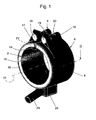
- Fig. 1 shows a perspective view of the heater with the base body 2 and with the surrounding clamping device 4, which includes a resilient clamping band 6 and a clamping device 8.
- the integrally formed and substantially up to 360 ° or only a few degrees less circumferentially extending base body 2 has a cylindrical contact surface 10, which is adapted to the outer surface of the component, not shown here.
- the main body 2 is formed substantially cylindrical and provided with a single both in the direction of the longitudinal axis 12, as well as in the radial direction through gap 14 and thus can by means of the clamping device 4 are tightened on the outer surface of the component.
- the tensioning device 8 is advantageously provided in the region of the gap 14.
- the clamping device 8 includes in the region of the ends and / or before the ends of the tension band 6 arranged separate brackets 16, 17, which are fixed to the tension band 6, in particular by welding. It is of particular importance that the brackets 16, 17 are separate and firmly connected to the strap components, because according to the invention, the ends of the strap in the gap 14 are bent radially inwardly, as will be explained below.
- the brackets 16, 17 are used to fix bolts 18, 19, wherein the one bolt 18 has a through hole and the other bolt 19 has an internal thread for a clamping screw 20.
- a cover 22 is further attached, which is expediently designed as a metal cap.
- the cover 22 By means of the cover 22, the electrical connection of the heating element and its connection conductor is covered, which are guided through the spout 24 to the outside. Also, the leads of an advantageous associated with the base body and as the heating element provided in the base body 2 temperature sensor are guided accordingly to the outside.
- the main body 2 consists of a good heat-conducting material and is designed as a one-piece prefabricated molded body.
- the main body is expediently a turned part and the production and / or processing of the contact surface 10 can be carried out in a simple manner and with high precision and adapted to the geometry of the outer surface of the component.
- the contact surface 10 in the context of the invention may alternatively also have a different geometry, for example a polygonal surface, namely matching and / or adapted to the geometry of the outer surface of the component.
- the continuous gap 14 may preferably be arranged in a plane inclined to the longitudinal axis 12 at a predetermined angle.
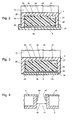
- the main body 2 shows a section through the heating device in an axial plane along the section line II according to FIG. 1.
- the main body 2 has a substantially U-shaped cross-sectional area with a bottom 25 and two outwardly pointing legs 26, 27, which are arranged at the axial ends of the base body 2. Between the legs 26, 27 and the bottom 25 thus a recess 28 is present, which extends over the circumference over an angle of approximately 360 ° and in which the prefabricated heating element 30 is arranged is.
- the wall surface 29 of the recess 28 is substantially smooth and / or closed and / or continuous, thus without grooves formed.
- the heating element 30 here includes schematically indicated electrical heating conductors 32, which are surrounded by a suitable electrical insulation 34 and / or embedded in them.
- the recess 28 is closed radially on the outside with the clamping band 6, which rests on the free ends of the legs 26, 27.
- the heating element 30 is defined in the recess 28, preferably under bias, pressed.
- the tension band 6 engages over the free ends of the legs 26, 27 and its axial edges 36, 37 are bent radially inwardly and are axially outside on the end faces of the legs 26, 27 at.
- an axial fixation of the tension band 6 is predetermined on the base body 2.
- a layer 40 in particular of electrically and / or heat-insulating material, is advantageously provided between the heating element 30 and the tensioning band 6.
- This layer 40 is preferably characterized by a compensation function and / or damping function.
- a temperature sensor 41 is advantageously arranged in the recess 28 of the main body 2.
- Fig. 3 an alternative embodiment is shown, according to which the free ends of the legs 26, 27 are provided with the recess 28 open circumferential grooves 38, wherein further radial projections 39 are present, which extend radially at least partially to the clamping band 6 and this thus fix in the axial direction with respect to the base body 2.
- the axial edges 42, 43 of the tension band 6 engage in the open circumferential grooves 38 of the legs 26, 27.
- FIG. 4 shows in enlarged detail the detail IV with the width 14 having a width in the circumferential direction gap 14 of the base body 2.
- the ends 46, 47 of the clamping band 6 in the radial direction inwardly bent into the gap 14 or angled, so that the tension band 6 is fixed with respect to the main body 2 in the circumferential direction.
- Due to the according to FIG. 2 radially inwardly bent edges 36, 37 and provided in FIG. 3 circumferential grooves 38 for receiving the edges 42, 43 of the clamping band 6 in combination with the bent into the gap 14 ends 46, 47 is the clamping band 6 fixed reliably on the base body 2.
Landscapes
- Engineering & Computer Science (AREA)
- General Engineering & Computer Science (AREA)
- Mechanical Engineering (AREA)
- Resistance Heating (AREA)
Abstract
Eine Heizvorrichtung zur Beheizung eines Bauteils enthält einen im wesentlichen ringförmigen Grundkörper (2), welcher eine an die Außenfläche des Bauteils abgestimmten und/oder angepaßte Anlagefläche (10) aufweist und aus einem gut wärmeleitenden Material besteht sowie eine radial nach außen offene Ausnehmung (28) zur Aufnahme eines Heizleiters (32) aufweist, und enthält ferner eine den Grundkörper (2) und den Heizleiter (32) umgebende Spanneinrichtung (4), mittels welcher die Heizvorrichtung auf der insbesondere zylindrischen Außenfläche des Bauteils festlegbar ist. Die Heizvorrichtung soll mit einem geringen konstruktiven Aufwand dahingehend weitergebildet werden, dass ein verbesserter Wärmeübergang auf das Bauteil erreicht wird, wobei ein geringes und/oder weitgehend gleichförmiges Temperaturgefälle vorgegeben werden soll. Hierzu wird vorgeschlagen, dass der Grundkörper (2) einteilig ausgebildet ist und einen im wesentlichen U-förmigen Querschnitt mit zwei an den axialen Enden angeordneten und radial nach außen gerichteten Schenkeln (26, 27) aufweist, zwischen welchen sich die Ausnehmung (28) befindet, dass der oder die Heizleiter (32) in eine elektrische Isolierung (34) eingebettet sind und zusammen mit dieser ein einheitliches Heizelement (30) bilden und dass das Heizelement (30) mit seiner Außenfläche an der durchgehenden Wandfläche (29) der Ausnehmung (28) mit vorgegebener Vorspannung anliegt, wobei das Heizelement (30) mittels des Spannbandes (6) in die Ausnehmung (28) gepreßt ist.

Description
Die Erfindung bezieht sich auf eine Heizvorrichtung gemäß den im Oberbegriff des Patentanspruchs 1 angegebenen Merkmalen.The invention relates to a heating device according to the features specified in the preamble of claim 1.
Aus der
Ferner sind aus der
Hiervon ausgehend liegt der Erfindung die Aufgabe zugrunde, mit einem geringen konstruktiven Aufwand die Heizvorrichtung dahingehend weiterzubilden, dass ein verbesserter Wärmeübergang auf das Bauteil erreicht wird, wobei ein geringes und/oder weitgehend gleichförmiges Temperaturgefälle vorgegeben werden soll. Die Heizvorrichtung soll einen geringen Fertigungs- und Materialaufwand erfordern und einen optimierten Wärmeverlauf ermöglichen. Des weiteren soll mit hoher Zuverlässigkeit und Reproduzierbarkeit ein reduziertes Temperaturgefälle zwischen dem Heizelement und dem Bauteil, welches insbesondere eine zylindrische Außenfläche aufweist, erreicht werden.Proceeding from this, the invention has the object, with a small design effort to further develop the heater so that an improved heat transfer to the component is achieved, with a low and / or substantially uniform temperature gradient to be specified. The heater should require a low production and material costs and allow an optimized heat history. Furthermore, with high reliability and reproducibility, a reduced temperature gradient should be achieved between the heating element and the component, which in particular has a cylindrical outer surface.
Die Lösung dieser Aufgabe erfolgt gemäß den Merkmalen des Patentanspruchs 1.The solution of this task is carried out according to the features of claim 1.
Die erfindungsgemäße Heizvorrichtung zeichnet sich durch einen funktionssicheren und den Anforderungen der Praxis gerechten Aufbau aus. Der Grundkörper besteht aus einem gut wärmeleitenden Material, und zwar je nach der geforderten Einsatztemperatur, insbesondere aus Aluminium, Messing oder vergleichbaren Werkstoffen bzw. Legierungen. Der Grundkörper und insbesondere dessen radial innen liegende Anlagefläche ist mit hoher Paßgenauigkeit auf die Außenfläche des Bauteils abgestimmt, wodurch ein optimaler homogener Wärmeverlauf erreicht wird. Der Grundkörper ist ein vorgefertigter einteiliger Formkörper, wobei die Anlagefläche problemlos und mit hoher Paßgenauigkeit entsprechend der Außenfläche des Bauteils herstellbar ist. Vor allem für Bauteile mit zylindrischer Außenfläche kann die Anlagefläche des Grundkörpers mit hoher Präzision entsprechend der zylindrischen Außenfläche ausgebildet werden. Im Rahmen der Erfindung kann die Heizvorrichtung bzw. deren Grundkörper auch für solche Bauteile ausgebildet sein, deren Außenflächen eine andere Geometrie aufweisen, wie beispielsweise polygonale Außenflächen, konkave oder konvexe Außenflächen, wobei durch entsprechende Bearbeitung der Anlagefläche deren Anpassung an die jeweiligen Außenfläche gleichwohl problemlos und mit hoher Paßgenauigkeit erfolgen kann. Die beiden Schenkel befinden sich, bezogen auf die Längsachse der Heizvorrichtung, jeweils an den beiden axialen Enden des Grundkörpers. Die Wandflächen der Ausnehmung sind im wesentlichen glatt ausgebildet und gewährleisten einen guten Wärmeübergang von dem bevorzugt unter vorgegebener Vorspannung anliegenden Heizelement. Nuten, Arretierungsmittel oder dergleichen für die einzelnen Heizleiter sind in den Wandflächen und/oder dem Grundkörper nicht vorhanden. Der Grundkörper besitzt einen im wesentlichen U-förmigen radial nach außen offenen Querschnitt, wobei die beiden in radialer Richtung sich erstreckenden Schenkel zur Auflage der Spanneinrichtung bzw. deren Spannband vorgesehen sind und wobei zwischen diesen Schenkeln die Ausnehmung mit dem Heizelement angeordnet ist. Der Grundkörper ist in Richtung seiner Längsachse sowohl radial als auch axial durchgehend geschlitzt ausgebildet. Aufgrund des somit vorhandenen Spaltes zwischen den Enden des sich über nahezu und/oder nur einige Grade kleiner als 360° einteilig ausgebildeten Grundkörpers kann dieser mittels der Spanneinrichtung fest und/oder mit vorgegebener Vorspannung auf der Außenfläche des Bauteils festgelegt werden, so dass mit hoher Funktionssicherheit und Reproduzierbarkeit ein geringes Temperaturgefälle zwischen dem Heizelement und dem Bauteil sichergestellt ist. Das Spannband weist bevorzugt einen im wesentlichen U-förmigen radial nach innen offenen Querschnitt auf, wobei die axialen Ränder radial nach innen zur Längsachse umgebogen sind und an den axialen Stirnflächen des jeweiligen Schenkels außen anliegen.The heating device according to the invention is characterized by a functionally reliable and the requirements of practice-fair design. The main body consists of a good heat-conducting material, depending on the required operating temperature, in particular of aluminum, brass or similar materials or alloys. The main body and in particular its radially inner contact surface is matched with high accuracy of fit to the outer surface of the component, whereby an optimal homogeneous heat history is achieved. The main body is a prefabricated one-piece molded body, wherein the contact surface can be produced easily and with high accuracy of fit according to the outer surface of the component. Especially for components with a cylindrical outer surface, the contact surface of the body can be formed with high precision corresponding to the cylindrical outer surface. In the context of the invention, the heater or its base body can also be designed for such components whose outer surfaces have a different geometry, such as polygonal outer surfaces, concave or convex outer surfaces, but by appropriate processing of the contact surface whose adaptation to the respective outer surface nevertheless easily and can be done with high accuracy. The two legs are located, based on the longitudinal axis of the heater, respectively at the two axial ends of the body. The wall surfaces of the recess are formed substantially smooth and ensure good heat transfer from the preferably under predetermined bias voltage applied heating element. Grooves, locking means or the like for the individual heating conductors are not present in the wall surfaces and / or the base body. The base body has a substantially U-shaped radially outwardly open cross-section, wherein the two extending in the radial direction legs for supporting the clamping device or the clamping band are provided and between these legs, the recess is arranged with the heating element. The main body is slotted in the direction of its longitudinal axis both radially and axially continuous. Due to the thus existing gap between the ends of over almost and / or only a few degrees smaller than 360 ° integrally formed body this can be fixed by means of the clamping device and / or with a predetermined bias on the outer surface of the component, so that with high reliability and reproducibility a low temperature gradient between the heating element and the component is ensured. The tension band preferably has a substantially U-shaped, radially inwardly open cross-section, wherein the axial edges are bent radially inward to the longitudinal axis and abut the axial end faces of the respective leg outside.
Der oder die elektrischen Heizleiter sind in eine elektrische Isolierung eingebettet und/oder von dieser umgeben, welche aus einem Werkstoff mit hoher Leitfähigkeit besteht. Der oder die elektrischen Heizleiter bilden das Heizelement, welches als vorgefertigte Baugruppe in die Ausnehmung des Grundkörpers eingesetzt ist und mittels der Spanneinrichtung unter vorgegebener Vorspannung festgelegt ist. Die Isolierung ist nicht als eine den Leiterdraht koaxial umgebende Schicht mit vorgegebener vergleichsweise geringer Dicke ausgebildet, sondern füllt die Zwischenräume zwischen den zweckmäßig in Umfangsrichtung nebeneinander und/oder größtenteils parallel liegenden einzelnen Heizleitern oder Teilen eines Heizleiters vollständig aus, und dient somit in bevorzugter Weise zur Arretierung und/oder Ausrichtung und/oder definierter Abstandsvorgabe zwischen den einzelnen Heizleitern und/oder Teilen derselben. Das Isoliermaterial ist in vorteilhafter Weise ein einteiliges Distanz- und Fixierungselement ausgebildet, in welches der oder die elektrischen Heizleiter bzw. deren Teile dauerhaft und/oder mit guter Paßgenauigkeit und/oder Ausrichtung zueinander integriert sind. Somit entfallen einzelne Nuten, Umlenkungen oder sonstige Arretierungsmittel im Grundkörper und/oder der genannten inneren Wandfläche des Grundkörpers. Des Weiteren ist die Querschnittsfläche des Isoliermaterials, abgesehen von den Querschnittsflächen des oder der elektrischen Heizleiter bzw. deren Teilen, wesentlich größer als die Querschnittsfläche der einzelnen und/oder sämtlicher Heizleiter bzw. deren Teile, wobei die genannten Querschnittsflächen in einer Axialebene liegen. Ferner ist es von besonderer Bedeutung, dass die elektrische Isolierung bzw. das Isoliermaterial des Heizelements eine vorgegebene Flexibilität und Verformbarkeit derart aufweist, dass es an die Wandfläche der Ausnehmung beim Festspannen mit hoher Funktionssicherheit angepaßt und/oder großflächig anliegt, wobei Fertigungsungenauigkeiten oder Unregelmäßigkeiten der Wandfläche zuverlässig ausgeglichen werden und ein optimierter Wärmeübergang sichergestellt ist.The one or more electrical heating conductors are embedded in an electrical insulation and / or surrounded by this, which consists of a material having high conductivity. The one or more electrical heating conductors form the heating element, which is used as a prefabricated module in the recess of the base body and is fixed by means of the clamping device under predetermined bias. The insulation is not formed as a coaxially surrounding the conductor wire layer with predetermined comparatively small thickness, but fills the spaces between the appropriately circumferentially next to each other and / or largely parallel single heaters or parts of a heat conductor completely, and thus serves in a preferred manner for locking and / or alignment and / or defined distance specification between the individual heating conductors and / or parts thereof. The insulating material is advantageously formed a one-piece spacer and fixing element, in which the one or more electrical heating conductors or their parts permanently and / or with good fit and / or alignment are integrated with each other. Thus eliminates individual grooves, deflections or other locking means in the base body and / or the said inner wall surface of the body. Furthermore, the cross-sectional area of the insulating material, apart from the cross-sectional areas of the electrical heating conductor or parts thereof, is substantially greater than the cross-sectional area of the individual and / or all heating conductors or their parts, said cross-sectional areas lying in an axial plane. Furthermore, it is of particular importance that the electrical insulation or the insulating material of the heating element has a predetermined flexibility and deformability such that it matches the wall surface of the recess during clamping with high reliability and / or applied over a large area, manufacturing inaccuracies or irregularities of the wall surface be reliably compensated and an optimized heat transfer is ensured.
Die elektrische Isolierung ist erfindungsgemäß ein Puffer mit einer Ausgleichsfunktion. Der von der Spanneinrichtung auf das Heizelement einwirkende Druck wird von der Isolierung aufgenommen und/oder großflächig verteilt, so dass eine Überlastung oder Beschädigung des oder der Heizleiter vermieden wird. Da die Spanneinrichtung auf den Schenkeln des Innenkörpers aufliegt, ist bei der Montage bzw. beim Festspannen eine Begrenzung der Vorspannkraft und/oder der Druckbelastung des Heizelements sichergestellt. Die Dimensionierung der Ausnehmung einerseits und des verformbaren und/oder nachgiebigen Heizelements andererseits sind derart aufeinander abgestimmt, dass das Heizelement nach der Montage unter vorgegebener Vorspannung in die Ausnehmung eingepreßt ist und an deren Wandfläche fest anliegt, wobei durch Auflage der Spanneinrichtung auf den radial außen liegenden Umfangsflächen der Schenkel die Vorspannung definiert begrenzt ist.The electrical insulation according to the invention is a buffer with a compensation function. The pressure acting on the heating element from the clamping device is absorbed by the insulation and / or distributed over a large area, so that overloading or damage of the heating element or conductors is avoided. Since the clamping device rests on the legs of the inner body, a limitation of the biasing force and / or the pressure load of the heating element is ensured during assembly or during clamping. The dimensioning of the recess on the one hand and the deformable and / or flexible heating element on the other hand are coordinated so that the heating element is pressed after assembly under predetermined bias in the recess and firmly applied to the wall surface, wherein by supporting the clamping device on the radially outer Circumferential surfaces of the legs defined the bias is limited.
Die Spanneinrichtung enthält ein den ringförmigen Grundkörper umgebendes und auf dem oder den freien Enden des oder der genannten Schenkel aufliegendes Spannband. Weiterhin enthält die Spanneinrichtung eine Spannvorrichtung zum Festspannen des Grundkörpers und des Heizelements, wobei eine Spannschraube oder sonstige Spannelemente, Hebelverbindungen oder dergleichen vorgesehen sind. Die Abmessungen der genannten Ausnehmung und des Heizelements sind derart aufeinander abgestimmt, dass mittels der Spanneinrichtung das Heizelement definiert in radialer Richtung unter Vorspannung an den Grundkörper gepreßt wird, wodurch einerseits ein optimierter und/oder gleichförmiger Wärmeübergang erreicht wird und andererseits mittels der Schenkel eine unzulässig hohe Vorspannung auf das Heizelement vermieden wird. Die Spanneinrichtung und insbesondere deren Spannband weist in bevorzugter Weise eine um einen vorgegebenen Betrag geringere Wärmeleitfähigkeit auf als der Grundkörper. Je nach Einsatztemperatur ist ein geeignetes Heizelement vorgesehen mit insbesondere Glimmer, mineralischer- oder keramischer Isolierung. Auch kann das Heizelement optional zusätzlich mit einer Schicht und/oder mineralischen Wärmeisolierung abgedeckt und/oder umgeben sein. Die Spanneinrichtung, insbesondere deren Spannband, ist in vorteilhafter Weise federnd ausgebildet und besteht vorteilhaft aus einer geeigneten Legierung, wie insbesondere Edelstahl.The tensioning device includes a clamping band surrounding the annular base body and resting on the one or more free ends of the leg (s). Furthermore, the clamping device includes a clamping device for clamping the base body and the heating element, wherein a clamping screw or other clamping elements, lever connections or the like are provided. The dimensions of said recess and the heating element are coordinated such that by means of the clamping device, the heating element is pressed in the radial direction under bias to the body, whereby on the one hand an optimized and / or uniform heat transfer is achieved and on the other hand by means of the legs an impermissibly high Pre-tension on the heating element is avoided. The tensioning device, and in particular its tensioning band, preferably has a lower thermal conductivity than the base body by a predetermined amount. Depending on the operating temperature, a suitable heating element is provided with in particular mica, mineral or ceramic insulation. Also, the heating element may optionally be additionally covered and / or surrounded by a layer and / or mineral heat insulation. The tensioning device, in particular its tensioning band, is advantageously resilient and advantageously consists of a suitable alloy, in particular stainless steel.
Die Enden des Spannbandes sind im Bereich des genannten Spaltes in bevorzugter Weise radial nach innen umgebogen und/oder abgekantet, wodurch eine definierte und in Umfangsrichtung fixierte Festlegung der Spanneinrichtung bezüglich des Grundkörpers sichergestellt ist. Des weiteren ist die Spanneinrichtung in axialer Richtung bezüglich des Grundkörpers fixiert, insbesondere in Nuten des oder der Schenkel des Grundkörpers oder mittels der radial nach innen umgebogenen Ränder. In einer bevorzugten Ausgestaltung der Erfindung übergreift die Spanneinrichtung bzw. deren Spannband jeweils die End- oder Umfangsflächen der Schenkel vollständig, wobei die axialen Ränder des Spannbandes radial nach innen zur Längsachse gebogen sind und an den axialen Endflächen oder Stirnflächen der Schenkel bzw. des Grundkörpers anliegen. Somit ist eine definierte und/oder feste mechanische Verbindung zwischen den einzelnen Bauteilen erreicht. Aufgrund der federnden Wirkung und/oder federelastischen Ausbildung der Spanneinrichtung, insbesondere deren Spannband, wird beim Lösen der Spanneinrichtung, insbesondere der genannten Spannschraube, der Grundkörper aufgeweitet, wodurch eine leichte Montage ermöglicht ist.The ends of the tensioning band are preferably radially inwardly bent in the region of said gap and / or folded, whereby a defined and fixed in the circumferential direction fixing the clamping device is ensured with respect to the body. Furthermore, the clamping device is fixed in the axial direction with respect to the base body, in particular in grooves of the limb of the body or by means of the radially inwardly bent edges. In a preferred embodiment of the invention, the clamping device or its clamping band engages over the end or peripheral surfaces of the legs completely, wherein the axial edges of the clamping band are bent radially inwardly to the longitudinal axis and abut the axial end surfaces or end faces of the legs or of the base body , Thus, a defined and / or fixed mechanical connection between the individual components is achieved. Due to the resilient action and / or elastic design of the clamping device, in particular its clamping band, the base body is widened when loosening the clamping device, in particular the said clamping screw, whereby an easy assembly is possible.
Für den elektrischen Anschluss des Heizelements bzw. dessen elektrischen Leiter sind vorteilhaft hitzebeständige und/oder flexible und/oder in der Länge variierende Anschlußleiter vorgesehen. Im Verbindungsbereich der elektrischen Leiter des Heizelements und den Anschlußleitern ist vorteilhaft eine Abdeckung vorgesehen, bevorzugt eine geeignete bzw. angepaßte Metallkappe, welche mit der Spanneinrichtung und insbesondere deren Spannband in geeigneter Weise verbunden ist, bevorzugt durch Lötung oder Schweißung. Ferner ist optional zusätzlich in vorteilhafter Weise noch am Grundkörper, insbesondere in dessen Ausnehmung, ein Temperaturfühler vorgesehen, dessen zugeordnete Anschlußleiter ebenso wie die des oder der Heizleiter des Heizelements zweckmäßig durch die genannte Abdeckung nach außen geführt sind.For the electrical connection of the heating element or its electrical conductors heat-resistant and / or flexible and / or varying in length connecting conductor are advantageously provided. In the connecting region of the electrical conductors of the heating element and the connecting conductors is advantageously provided a cover, preferably a suitable or adapted metal cap, which is connected to the clamping device and in particular its clamping band in a suitable manner, preferably by soldering or welding. Furthermore, a temperature sensor is optionally additionally provided in an advantageous manner even on the body, in particular in the recess, the associated terminal conductor as well as the or the heating element of the heating element are suitably guided by said cover to the outside.
Besondere Ausgestaltungen und Weiterbildungen der Erfindung sind in den Unteransprüchen und der weiteren Beschreibung angegeben.Particular refinements and developments of the invention are specified in the subclaims and the further description.
Die Erfindung wird nachfolgend anhand der besonderen in der Zeichnung dargestellten Ausführungsbeispiele näher erläutert, ohne dass insoweit eine Beschränkung erfolgt. Es zeigen:
- Fig. 1
- eine perspektivische Ansicht der Heizvorrichtung,
- Fig. 2
- einen Schnitt entlang Schnittlinie II gemäß Fig. 1,
- Fig. 3
- einen Schnitt einer alternativen Ausgestaltung der Heizvorrichtung entlang Schnittlinie II,
- Fig. 4
- vergrößert und in einer radialen Schnittebene das Detail IV gemäß Fig. 1.
- Fig. 1
- a perspective view of the heater,
- Fig. 2
- a section along section line II of FIG. 1,
- Fig. 3
- a section of an alternative embodiment of the heater along section line II,
- Fig. 4
- enlarged and in a radial sectional plane, the detail IV of FIG. 1st
Fig. 1 zeigt in perspektivischer Darstellung die Heizvorrichtung mit dem Grundkörper 2 und mit der diesen umgebenden Spanneinrichtung 4, welche ein federndes Spannband 6 und eine Spannvorrichtung 8 enthält. Der einteilig ausgebildete und sich im wesentlichen bis zu 360° oder nur wenige Grad weniger in Umfangsrichtung erstreckende Grundkörper 2 besitzt eine zylindrische Anlagefläche 10, welche an die Außenfläche des hier nicht dargestellten Bauteils angepaßt ist. Der Grundkörper 2 ist im wesentlichen zylindrisch ausgebildet und mit einem einzigen sowohl in Richtung der Längsachse 12, als auch in radialer Richtung durchgehenden Spalt 14 versehen und kann somit mittels der Spanneinrichtung 4 auf der Außenfläche des Bauteils festgespannt werden. Die Spannvorrichtung 8 ist vorteilhaft im Bereich des Spaltes 14 vorgesehen. Die Spannvorrichtung 8 enthält im Bereich der Enden und/oder vor den Enden des Spannbandes 6 angeordnete separate Halterungen 16, 17, welche mit dem Spannband 6 fest, insbesondere durch Schweißung verbunden sind. Es ist von besonderer Bedeutung, dass die Halterungen 16, 17 separate und fest mit dem Spannband verbundene Bauteile sind, denn erfindungsgemäß sind die Enden des Spannbandes im Spalt 14 radial nach innen umgebogen, wie nachfolgend noch zu erläutern ist. Die Halterungen 16, 17 dienen zur Festlegung von Bolzen 18, 19, wobei der eine Bolzen 18 eine Durchgangsbohrung und der andere Bolzen 19 ein Innengewinde für eine Spannschraube 20 aufweisen. An dem Spannband 6 ist ferner eine Abdeckung 22 befestigt, welche zweckmäßig als eine Metallkappe ausgebildet ist. Mittels der Abdeckung 22 wird die elektrische Verbindung des Heizelements und deren Anschlußleiter abgedeckt, welche durch die Tülle 24 nach außen geführt sind. Auch die Anschlußleiter eines vorteilhaft dem Grundkörper zugeordneten und wie das Heizelement im Grundkörper 2 vorgesehenen Temperaturfühlers sind entsprechend nach außen geführt.Fig. 1 shows a perspective view of the heater with the
Der Grundkörper 2 besteht aus einem gut wärmeleitenden Material und ist als einstückiger vorgefertigter Formkörper ausgebildet. Der Grundkörper ist zweckmäßig ein Drehteil und die Herstellung und/oder die Bearbeitung der Anlagefläche 10 ist in einfacher Weise und mit hoher Präzision durchführbar und an die Geometrie der Außenfläche des Bauteils angepaßt. Es sei hier ausdrücklich festgehalten, dass die Anlagefläche 10 im Rahmen der Erfindung alternativ auch eine andere Geometrie, beispielsweise eine Polygonfläche, aufweisen kann, und zwar übereinstimmend und/oder angepaßt an die Geometrie der Außenfläche des Bauteils. Des weiteren kann der durchgehende Spalt 14 bevorzugt in einer zur Längsachse 12 unter einem vorgegebenen Winkel schrägstehenden Ebene angeordnet sein.The
Fig. 2 zeigt einen Schnitt durch die Heizvorrichtung in einer Axialebene entlang der Schnittlinie II gemäß Fig. 1. Wie ersichtlich, besitzt der Grundkörper 2 eine im wesentlichen U-förmige Querschnittsfläche mit einem Boden 25 sowie zwei in radialer Richtung nach außen weisenden Schenkeln 26, 27, welche an den axialen Enden des Grundkörpers 2 angeordnet sind. Zwischen den Schenkeln 26, 27 und dem Boden 25 ist somit eine Ausnehmung 28 vorhanden, welche sich über den Umfang über einen Winkel von annähernd 360° erstreckt und in welcher das vorgefertigte Heizelement 30 angeordnet ist. Die Wandfläche 29 der Ausnehmung 28 ist im wesentlichen glatt und/oder geschlossen und/oder durchgehend, somit ohne Nuten, ausgebildet. Das Heizelement 30 enthält hier schematisch angedeutete elektrische Heizleiter 32, welche von einer geeigneten elektrischen Isolierung 34 umgeben und/oder in diese eingebettet sind. Die Ausnehmung 28 wird radial außen mit dem Spannband 6 abgeschlossen, welches auf den freien Enden der Schenkel 26, 27 aufliegt. Mittels des Spannbandes 6 wird das Heizelement 30 definiert in die Ausnehmung 28, bevorzugt unter Vorspannung, gepreßt. Das Spannband 6 übergreift die freien Enden der Schenkel 26, 27 und seine axialen Ränder 36, 37 sind radial nach innen umgebogen und liegen axial außen an den Stirnflächen der Schenkel 26, 27 an. Somit ist eine axiale Fixierung des Spannbandes 6 auf dem Grundkörper 2 vorgegeben. Ferner ist in vorteilhafter Weise zwischen dem Heizelement 30 und dem Spannband 6 eine Schicht 40 insbesondere aus elektrisch- und/oder wärmeisolierendem Material vorgesehen. Diese Schicht 40 zeichnet sich in bevorzugter Weise durch eine Ausgleichsfunktion und/oder Dämpfungsfunktion aus. Des Weiteren ist vorteilhaft in der Ausnehmung 28 des Grundkörpers 2 ein Temperaturfühler 41 angeordnet.2 shows a section through the heating device in an axial plane along the section line II according to FIG. 1. As can be seen, the
In Fig. 3 ist eine alternative Ausgestaltung dargestellt, gemäß welcher die freien Enden der Schenkel 26, 27 mit zur Ausnehmung 28 offenen Umfangsnuten 38 versehen sind, wobei ferner radiale Ansätze 39 vorhanden sind, welche sich radial zumindest teilweise bis zum Spannband 6 erstrecken und dieses somit in axialer Richtung bezüglich des Grundkörpers 2 fixieren. Bei diesem Ausführungsbeispiel greifen die axialen Ränder 42, 43 des Spannbandes 6 in die offenen Umfangsnuten 38 der Schenkel 26, 27 ein.In Fig. 3, an alternative embodiment is shown, according to which the free ends of the
Fig. 4 zeigt vergrößert im Schnitt das Detail IV mit dem in Umfangsrichtung eine Breite 44 aufweisenden Spalt 14 des Grundkörpers 2. Wie ersichtlich, sind die Enden 46, 47 des Spannbandes 6 in radialer Richtung nach innen in den Spalt 14 umgebogen bzw. abgewinkelt, so dass das Spannband 6 bezüglich des Grundkörpers 2 in Umfangsrichtung fixiert ist. Aufgrund der gemäß Fig. 2 radial nach innen umgebogenen Ränder 36, 37 bzw. der gemäß Fig. 3 vorgesehenen Umfangsnuten 38 zur Aufnahme der Ränder 42, 43 des Spannbandes 6 in Kombination mit den in den Spalt 14 umgebogenen Enden 46, 47 ist das Spannband 6 zuverlässig auf dem Grundkörper 2 festgelegt. Das sich über den Umfang erstreckende, hier nicht weiter dargestellte Heizelement endet beidseits des Spaltes 14.4 shows in enlarged detail the detail IV with the
- 22
- Grundkörperbody
- 44
- Spanneinrichtungtensioning device
- 66
- Spannbandstrap
- 88th
- Spannvorrichtungjig
- 1010
- Anlagefläche von 2Investment area of 2
- 1212
- Längsachselongitudinal axis
- 1414
- Spalt in 2Gap in 2
- 16, 1716, 17
- Halterung von 4Holder of 4
- 18, 1918, 19
- Bolzenbolt
- 2020
- Spannschraubeclamping screw
- 2222
- Abdeckung / MetallkappeCover / metal cap
- 2424
- Tüllespout
- 2525
- Boden von 2Bottom of 2
- 26, 2726, 27
- Schenkel von 2Thighs of 2
- 2828
- Ausnehmung in 2Recess in 2
- 2929
- Wandfläche von 28Wall area of 28
- 3030
- Heizelementheating element
- 3232
- Heizleiter von 30Heating conductor of 30
- 3434
- elektrische Isolierung von 30electrical insulation of 30
- 36, 3736, 37
- axialer Rand von 6axial edge of 6
- 3838
- Umfangsnut in 26, 27Circumferential groove in 26, 27
- 3939
- radialer Ansatz von 26, 27radial approach of 26, 27
- 4040
- Schichtlayer
- 4141
- Temperaturfühlertemperature sensor
- 42, 4342, 43
- axialer Rand von 6axial edge of 6
- 4444
- Breite von 14Width of 14
- 46,4746.47
- Ende von 6End of 6
Claims (10)
dadurch gekennzeichnet, dass der Grundkörper (2) einteilig ausgebildet ist und einen im wesentlichen U-förmigen Querschnitt mit zwei an den axialen Enden angeordneten und radial nach außen gerichteten Schenkeln (26, 27) aufweist, zwischen welchen sich die Ausnehmung (28) befindet,
dass der oder die Heizleiter (32) in eine elektrische Isolierung (34) eingebettet sind und zusammen mit dieser ein einheitliches Heizelement (30) bilden
und dass das Heizelement (30) mit seiner Außenfläche an der durchgehenden Wandfläche (29) der Ausnehmung (28) mit vorgegebener Vorspannung anliegt, wobei das Heizelement (30) mittels des Spannbandes (6) in die Ausnehmung (28) gepreßt ist.Heating device for heating a component, comprising a substantially annular base body (2) which has a matched to the outer surface of the component and / or adapted contact surface (10) and consists of a highly thermally conductive material and a radially outwardly open recess (28) for receiving a heating conductor (32), and further comprising a clamping device (4) surrounding the base body (2) and the heating conductor (32), by means of which the heating device can be fixed on the particular cylindrical outer surface of the component,
characterized in that the base body (2) is integrally formed and has a substantially U-shaped cross section with two arranged at the axial ends and radially outwardly directed legs (26, 27), between which the recess (28) is located,
in that the heating conductor (s) (32) are embedded in an electrical insulation (34) and together with the latter form a uniform heating element (30)
and that the heating element (30) abuts with its outer surface on the continuous wall surface (29) of the recess (28) with a predetermined bias, wherein the heating element (30) by means of the clamping band (6) is pressed into the recess (28).
Applications Claiming Priority (1)
| Application Number | Priority Date | Filing Date | Title |
|---|---|---|---|
| DE202006004913U DE202006004913U1 (en) | 2006-03-24 | 2006-03-24 | heater |
Publications (3)
| Publication Number | Publication Date |
|---|---|
| EP1838136A2 true EP1838136A2 (en) | 2007-09-26 |
| EP1838136A3 EP1838136A3 (en) | 2013-02-27 |
| EP1838136B1 EP1838136B1 (en) | 2015-04-29 |
Family
ID=36776670
Family Applications (1)
| Application Number | Title | Priority Date | Filing Date |
|---|---|---|---|
| EP20070006056 Not-in-force EP1838136B1 (en) | 2006-03-24 | 2007-03-23 | Heating device |
Country Status (2)
| Country | Link |
|---|---|
| EP (1) | EP1838136B1 (en) |
| DE (1) | DE202006004913U1 (en) |
Cited By (1)
| Publication number | Priority date | Publication date | Assignee | Title |
|---|---|---|---|---|
| CN119629783A (en) * | 2024-11-25 | 2025-03-14 | 北京航空航天大学 | A heat source device for Rijke tube and use method thereof |
Families Citing this family (2)
| Publication number | Priority date | Publication date | Assignee | Title |
|---|---|---|---|---|
| ITBO20060671A1 (en) * | 2006-09-29 | 2008-03-30 | Poli Off Mecc Spa | JERSEY FLEXIBLE THERMO-OPENING. |
| CN102248677A (en) * | 2011-06-21 | 2011-11-23 | 刘均平 | Adhesive connecting process for inner pipe of casting polyurethane conveying pipe and special clamp thereof |
Family Cites Families (1)
| Publication number | Priority date | Publication date | Assignee | Title |
|---|---|---|---|---|
| DE2145067A1 (en) * | 1971-09-09 | 1973-03-22 | Dickersbach & Co Heinrich | ELECTRIC RING RADIATOR AND METHOD FOR ITS MANUFACTURING |
-
2006
- 2006-03-24 DE DE202006004913U patent/DE202006004913U1/en not_active Expired - Lifetime
-
2007
- 2007-03-23 EP EP20070006056 patent/EP1838136B1/en not_active Not-in-force
Cited By (1)
| Publication number | Priority date | Publication date | Assignee | Title |
|---|---|---|---|---|
| CN119629783A (en) * | 2024-11-25 | 2025-03-14 | 北京航空航天大学 | A heat source device for Rijke tube and use method thereof |
Also Published As
| Publication number | Publication date |
|---|---|
| DE202006004913U1 (en) | 2006-07-20 |
| EP1838136B1 (en) | 2015-04-29 |
| EP1838136A3 (en) | 2013-02-27 |
Similar Documents
| Publication | Publication Date | Title |
|---|---|---|
| WO2009109484A1 (en) | Clamp fitting for a hose end | |
| DE2211089A1 (en) | Adjustable, spring-loaded temperature sensor device | |
| DE202021102620U1 (en) | Heating device for an exhaust system and an exhaust system | |
| EP2109201A2 (en) | Device for electromagnetically sealed assembly of a cable | |
| DE102016123388B4 (en) | profile clip | |
| DE3632614A1 (en) | CERAMIC / METAL JOINT CONSTRUCTION | |
| EP3211190B1 (en) | Connector assembly with at least one connector and at least one fluid line | |
| EP3904647A1 (en) | Connection unit for a waste gas heater | |
| DE102013111303A1 (en) | Electric heating element | |
| DE2322690A1 (en) | GLOW PLUG | |
| EP2837815A1 (en) | Fuel distribution rail | |
| EP3093545B1 (en) | Pipe connection device for connecting two pipe ends, especially two pipe ends in an exhaust line of a combustion engine | |
| EP1838136B1 (en) | Heating device | |
| DE102011052822A1 (en) | Camshaft, in particular for motor vehicle engines | |
| DE29580485U1 (en) | Device for connecting pipe sections | |
| DE19508979A1 (en) | Helical compression spring | |
| EP1407256A2 (en) | Gas sensor | |
| DE19833861A1 (en) | Gas measurement probe, especially to determine gas content in exhaust gas of internal combustion engines; has spring-biased sensor that moves under pressure | |
| EP1610425A1 (en) | Brush spring for slip-ring current collector | |
| EP3228891A1 (en) | Device and method for resetting a bearing shell which has slid out of a recess on a shaft | |
| DE102019121345A1 (en) | Heating device for preheating an exhaust gas flow and vehicle | |
| DE102005009927B4 (en) | Thermocouple thermocouple with compensating cable | |
| DE2063097B1 (en) | Longitudinally split cable sleeve with cable clamp | |
| DE10249872B4 (en) | Mobile fuel heater with a glow plug / flame guard | |
| DE102007018000A1 (en) | Sensor housing and ceramic form unit interconnection for gas sensor, has inner body held at ring shoulder that is formed at stopper in transition for pipe section of protective pipe |
Legal Events
| Date | Code | Title | Description |
|---|---|---|---|
| PUAI | Public reference made under article 153(3) epc to a published international application that has entered the european phase |
Free format text: ORIGINAL CODE: 0009012 |
|
| AK | Designated contracting states |
Kind code of ref document: A2 Designated state(s): AT BE BG CH CY CZ DE DK EE ES FI FR GB GR HU IE IS IT LI LT LU LV MC MT NL PL PT RO SE SI SK TR |
|
| AX | Request for extension of the european patent |
Extension state: AL BA HR MK YU |
|
| PUAL | Search report despatched |
Free format text: ORIGINAL CODE: 0009013 |
|
| AK | Designated contracting states |
Kind code of ref document: A3 Designated state(s): AT BE BG CH CY CZ DE DK EE ES FI FR GB GR HU IE IS IT LI LT LU LV MC MT NL PL PT RO SE SI SK TR |
|
| AX | Request for extension of the european patent |
Extension state: AL BA HR MK RS |
|
| RIC1 | Information provided on ipc code assigned before grant |
Ipc: H05B 3/58 20060101AFI20130122BHEP |
|
| 17P | Request for examination filed |
Effective date: 20130709 |
|
| AKX | Designation fees paid |
Designated state(s): AT BE BG CH CY CZ DE DK EE ES FI FR GB GR HU IE IS IT LI LT LU LV MC MT NL PL PT RO SE SI SK TR |
|
| GRAP | Despatch of communication of intention to grant a patent |
Free format text: ORIGINAL CODE: EPIDOSNIGR1 |
|
| INTG | Intention to grant announced |
Effective date: 20141107 |
|
| GRAS | Grant fee paid |
Free format text: ORIGINAL CODE: EPIDOSNIGR3 |
|
| GRAP | Despatch of communication of intention to grant a patent |
Free format text: ORIGINAL CODE: EPIDOSNIGR1 |
|
| INTG | Intention to grant announced |
Effective date: 20150306 |
|
| GRAA | (expected) grant |
Free format text: ORIGINAL CODE: 0009210 |
|
| AK | Designated contracting states |
Kind code of ref document: B1 Designated state(s): AT BE BG CH CY CZ DE DK EE ES FI FR GB GR HU IE IS IT LI LT LU LV MC MT NL PL PT RO SE SI SK TR |
|
| REG | Reference to a national code |
Ref country code: GB Ref legal event code: FG4D Free format text: NOT ENGLISH |
|
| REG | Reference to a national code |
Ref country code: CH Ref legal event code: EP |
|
| REG | Reference to a national code |
Ref country code: AT Ref legal event code: REF Ref document number: 725031 Country of ref document: AT Kind code of ref document: T Effective date: 20150515 |
|
| REG | Reference to a national code |
Ref country code: IE Ref legal event code: FG4D Free format text: LANGUAGE OF EP DOCUMENT: GERMAN |
|
| REG | Reference to a national code |
Ref country code: DE Ref legal event code: R096 Ref document number: 502007013894 Country of ref document: DE Effective date: 20150603 |
|
| REG | Reference to a national code |
Ref country code: NL Ref legal event code: T3 |
|
| REG | Reference to a national code |
Ref country code: LT Ref legal event code: MG4D |
|
| PG25 | Lapsed in a contracting state [announced via postgrant information from national office to epo] |
Ref country code: PT Free format text: LAPSE BECAUSE OF FAILURE TO SUBMIT A TRANSLATION OF THE DESCRIPTION OR TO PAY THE FEE WITHIN THE PRESCRIBED TIME-LIMIT Effective date: 20150831 Ref country code: LT Free format text: LAPSE BECAUSE OF FAILURE TO SUBMIT A TRANSLATION OF THE DESCRIPTION OR TO PAY THE FEE WITHIN THE PRESCRIBED TIME-LIMIT Effective date: 20150429 Ref country code: FI Free format text: LAPSE BECAUSE OF FAILURE TO SUBMIT A TRANSLATION OF THE DESCRIPTION OR TO PAY THE FEE WITHIN THE PRESCRIBED TIME-LIMIT Effective date: 20150429 Ref country code: ES Free format text: LAPSE BECAUSE OF FAILURE TO SUBMIT A TRANSLATION OF THE DESCRIPTION OR TO PAY THE FEE WITHIN THE PRESCRIBED TIME-LIMIT Effective date: 20150429 |
|
| PG25 | Lapsed in a contracting state [announced via postgrant information from national office to epo] |
Ref country code: IS Free format text: LAPSE BECAUSE OF FAILURE TO SUBMIT A TRANSLATION OF THE DESCRIPTION OR TO PAY THE FEE WITHIN THE PRESCRIBED TIME-LIMIT Effective date: 20150829 Ref country code: LV Free format text: LAPSE BECAUSE OF FAILURE TO SUBMIT A TRANSLATION OF THE DESCRIPTION OR TO PAY THE FEE WITHIN THE PRESCRIBED TIME-LIMIT Effective date: 20150429 Ref country code: GR Free format text: LAPSE BECAUSE OF FAILURE TO SUBMIT A TRANSLATION OF THE DESCRIPTION OR TO PAY THE FEE WITHIN THE PRESCRIBED TIME-LIMIT Effective date: 20150730 |
|
| PG25 | Lapsed in a contracting state [announced via postgrant information from national office to epo] |
Ref country code: DK Free format text: LAPSE BECAUSE OF FAILURE TO SUBMIT A TRANSLATION OF THE DESCRIPTION OR TO PAY THE FEE WITHIN THE PRESCRIBED TIME-LIMIT Effective date: 20150429 Ref country code: EE Free format text: LAPSE BECAUSE OF FAILURE TO SUBMIT A TRANSLATION OF THE DESCRIPTION OR TO PAY THE FEE WITHIN THE PRESCRIBED TIME-LIMIT Effective date: 20150429 |
|
| REG | Reference to a national code |
Ref country code: DE Ref legal event code: R097 Ref document number: 502007013894 Country of ref document: DE |
|
| PG25 | Lapsed in a contracting state [announced via postgrant information from national office to epo] |
Ref country code: RO Free format text: LAPSE BECAUSE OF NON-PAYMENT OF DUE FEES Effective date: 20150429 Ref country code: SK Free format text: LAPSE BECAUSE OF FAILURE TO SUBMIT A TRANSLATION OF THE DESCRIPTION OR TO PAY THE FEE WITHIN THE PRESCRIBED TIME-LIMIT Effective date: 20150429 Ref country code: CZ Free format text: LAPSE BECAUSE OF FAILURE TO SUBMIT A TRANSLATION OF THE DESCRIPTION OR TO PAY THE FEE WITHIN THE PRESCRIBED TIME-LIMIT Effective date: 20150429 Ref country code: PL Free format text: LAPSE BECAUSE OF FAILURE TO SUBMIT A TRANSLATION OF THE DESCRIPTION OR TO PAY THE FEE WITHIN THE PRESCRIBED TIME-LIMIT Effective date: 20150429 |
|
| PLBE | No opposition filed within time limit |
Free format text: ORIGINAL CODE: 0009261 |
|
| STAA | Information on the status of an ep patent application or granted ep patent |
Free format text: STATUS: NO OPPOSITION FILED WITHIN TIME LIMIT |
|
| REG | Reference to a national code |
Ref country code: FR Ref legal event code: PLFP Year of fee payment: 10 |
|
| 26N | No opposition filed |
Effective date: 20160201 |
|
| PG25 | Lapsed in a contracting state [announced via postgrant information from national office to epo] |
Ref country code: IT Free format text: LAPSE BECAUSE OF FAILURE TO SUBMIT A TRANSLATION OF THE DESCRIPTION OR TO PAY THE FEE WITHIN THE PRESCRIBED TIME-LIMIT Effective date: 20150429 |
|
| PG25 | Lapsed in a contracting state [announced via postgrant information from national office to epo] |
Ref country code: SI Free format text: LAPSE BECAUSE OF FAILURE TO SUBMIT A TRANSLATION OF THE DESCRIPTION OR TO PAY THE FEE WITHIN THE PRESCRIBED TIME-LIMIT Effective date: 20150429 |
|
| PG25 | Lapsed in a contracting state [announced via postgrant information from national office to epo] |
Ref country code: BE Free format text: LAPSE BECAUSE OF NON-PAYMENT OF DUE FEES Effective date: 20160331 |
|
| PG25 | Lapsed in a contracting state [announced via postgrant information from national office to epo] |
Ref country code: MC Free format text: LAPSE BECAUSE OF FAILURE TO SUBMIT A TRANSLATION OF THE DESCRIPTION OR TO PAY THE FEE WITHIN THE PRESCRIBED TIME-LIMIT Effective date: 20150429 Ref country code: LU Free format text: LAPSE BECAUSE OF FAILURE TO SUBMIT A TRANSLATION OF THE DESCRIPTION OR TO PAY THE FEE WITHIN THE PRESCRIBED TIME-LIMIT Effective date: 20160323 |
|
| REG | Reference to a national code |
Ref country code: IE Ref legal event code: MM4A |
|
| PG25 | Lapsed in a contracting state [announced via postgrant information from national office to epo] |
Ref country code: IE Free format text: LAPSE BECAUSE OF NON-PAYMENT OF DUE FEES Effective date: 20160323 |
|
| REG | Reference to a national code |
Ref country code: DE Ref legal event code: R082 Ref document number: 502007013894 Country of ref document: DE Representative=s name: REBLE KLOSE SCHMITT PARTNERSCHAFTSGESELLSCHAFT, DE |
|
| REG | Reference to a national code |
Ref country code: FR Ref legal event code: PLFP Year of fee payment: 11 |
|
| PG25 | Lapsed in a contracting state [announced via postgrant information from national office to epo] |
Ref country code: SE Free format text: LAPSE BECAUSE OF FAILURE TO SUBMIT A TRANSLATION OF THE DESCRIPTION OR TO PAY THE FEE WITHIN THE PRESCRIBED TIME-LIMIT Effective date: 20150429 |
|
| PG25 | Lapsed in a contracting state [announced via postgrant information from national office to epo] |
Ref country code: MT Free format text: LAPSE BECAUSE OF FAILURE TO SUBMIT A TRANSLATION OF THE DESCRIPTION OR TO PAY THE FEE WITHIN THE PRESCRIBED TIME-LIMIT Effective date: 20150429 |
|
| REG | Reference to a national code |
Ref country code: FR Ref legal event code: PLFP Year of fee payment: 12 |
|
| PG25 | Lapsed in a contracting state [announced via postgrant information from national office to epo] |
Ref country code: HU Free format text: LAPSE BECAUSE OF FAILURE TO SUBMIT A TRANSLATION OF THE DESCRIPTION OR TO PAY THE FEE WITHIN THE PRESCRIBED TIME-LIMIT; INVALID AB INITIO Effective date: 20070323 Ref country code: CY Free format text: LAPSE BECAUSE OF FAILURE TO SUBMIT A TRANSLATION OF THE DESCRIPTION OR TO PAY THE FEE WITHIN THE PRESCRIBED TIME-LIMIT Effective date: 20150429 |
|
| PG25 | Lapsed in a contracting state [announced via postgrant information from national office to epo] |
Ref country code: TR Free format text: LAPSE BECAUSE OF FAILURE TO SUBMIT A TRANSLATION OF THE DESCRIPTION OR TO PAY THE FEE WITHIN THE PRESCRIBED TIME-LIMIT Effective date: 20150429 |
|
| PG25 | Lapsed in a contracting state [announced via postgrant information from national office to epo] |
Ref country code: BG Free format text: LAPSE BECAUSE OF FAILURE TO SUBMIT A TRANSLATION OF THE DESCRIPTION OR TO PAY THE FEE WITHIN THE PRESCRIBED TIME-LIMIT Effective date: 20150429 |
|
| PG25 | Lapsed in a contracting state [announced via postgrant information from national office to epo] |
Ref country code: MT Free format text: LAPSE BECAUSE OF FAILURE TO SUBMIT A TRANSLATION OF THE DESCRIPTION OR TO PAY THE FEE WITHIN THE PRESCRIBED TIME-LIMIT Effective date: 20160323 |
|
| PGFP | Annual fee paid to national office [announced via postgrant information from national office to epo] |
Ref country code: CH Payment date: 20210324 Year of fee payment: 15 Ref country code: FR Payment date: 20210319 Year of fee payment: 15 Ref country code: NL Payment date: 20210319 Year of fee payment: 15 |
|
| PGFP | Annual fee paid to national office [announced via postgrant information from national office to epo] |
Ref country code: GB Payment date: 20210324 Year of fee payment: 15 Ref country code: DE Payment date: 20210323 Year of fee payment: 15 Ref country code: AT Payment date: 20210318 Year of fee payment: 15 |
|
| REG | Reference to a national code |
Ref country code: DE Ref legal event code: R119 Ref document number: 502007013894 Country of ref document: DE |
|
| REG | Reference to a national code |
Ref country code: CH Ref legal event code: PL |
|
| REG | Reference to a national code |
Ref country code: NL Ref legal event code: MM Effective date: 20220401 |
|
| REG | Reference to a national code |
Ref country code: AT Ref legal event code: MM01 Ref document number: 725031 Country of ref document: AT Kind code of ref document: T Effective date: 20220323 |
|
| GBPC | Gb: european patent ceased through non-payment of renewal fee |
Effective date: 20220323 |
|
| PG25 | Lapsed in a contracting state [announced via postgrant information from national office to epo] |
Ref country code: NL Free format text: LAPSE BECAUSE OF NON-PAYMENT OF DUE FEES Effective date: 20220401 Ref country code: LI Free format text: LAPSE BECAUSE OF NON-PAYMENT OF DUE FEES Effective date: 20220331 Ref country code: GB Free format text: LAPSE BECAUSE OF NON-PAYMENT OF DUE FEES Effective date: 20220323 Ref country code: FR Free format text: LAPSE BECAUSE OF NON-PAYMENT OF DUE FEES Effective date: 20220331 Ref country code: DE Free format text: LAPSE BECAUSE OF NON-PAYMENT OF DUE FEES Effective date: 20221001 Ref country code: CH Free format text: LAPSE BECAUSE OF NON-PAYMENT OF DUE FEES Effective date: 20220331 Ref country code: AT Free format text: LAPSE BECAUSE OF NON-PAYMENT OF DUE FEES Effective date: 20220323 |