EP1837529A1 - Hydraulic control device - Google Patents
Hydraulic control device Download PDFInfo
- Publication number
- EP1837529A1 EP1837529A1 EP06005669A EP06005669A EP1837529A1 EP 1837529 A1 EP1837529 A1 EP 1837529A1 EP 06005669 A EP06005669 A EP 06005669A EP 06005669 A EP06005669 A EP 06005669A EP 1837529 A1 EP1837529 A1 EP 1837529A1
- Authority
- EP
- European Patent Office
- Prior art keywords
- valve
- load pressure
- pressure
- control valve
- control device
- Prior art date
- Legal status (The legal status is an assumption and is not a legal conclusion. Google has not performed a legal analysis and makes no representation as to the accuracy of the status listed.)
- Granted
Links
Images
Classifications
-
- F—MECHANICAL ENGINEERING; LIGHTING; HEATING; WEAPONS; BLASTING
- F15—FLUID-PRESSURE ACTUATORS; HYDRAULICS OR PNEUMATICS IN GENERAL
- F15B—SYSTEMS ACTING BY MEANS OF FLUIDS IN GENERAL; FLUID-PRESSURE ACTUATORS, e.g. SERVOMOTORS; DETAILS OF FLUID-PRESSURE SYSTEMS, NOT OTHERWISE PROVIDED FOR
- F15B11/00—Servomotor systems without provision for follow-up action; Circuits therefor
- F15B11/16—Servomotor systems without provision for follow-up action; Circuits therefor with two or more servomotors
- F15B11/20—Servomotor systems without provision for follow-up action; Circuits therefor with two or more servomotors controlling several interacting or sequentially-operating members
-
- F—MECHANICAL ENGINEERING; LIGHTING; HEATING; WEAPONS; BLASTING
- F15—FLUID-PRESSURE ACTUATORS; HYDRAULICS OR PNEUMATICS IN GENERAL
- F15B—SYSTEMS ACTING BY MEANS OF FLUIDS IN GENERAL; FLUID-PRESSURE ACTUATORS, e.g. SERVOMOTORS; DETAILS OF FLUID-PRESSURE SYSTEMS, NOT OTHERWISE PROVIDED FOR
- F15B11/00—Servomotor systems without provision for follow-up action; Circuits therefor
- F15B11/16—Servomotor systems without provision for follow-up action; Circuits therefor with two or more servomotors
- F15B11/161—Servomotor systems without provision for follow-up action; Circuits therefor with two or more servomotors with sensing of servomotor demand or load
- F15B11/165—Servomotor systems without provision for follow-up action; Circuits therefor with two or more servomotors with sensing of servomotor demand or load for adjusting the pump output or bypass in response to demand
-
- F—MECHANICAL ENGINEERING; LIGHTING; HEATING; WEAPONS; BLASTING
- F15—FLUID-PRESSURE ACTUATORS; HYDRAULICS OR PNEUMATICS IN GENERAL
- F15B—SYSTEMS ACTING BY MEANS OF FLUIDS IN GENERAL; FLUID-PRESSURE ACTUATORS, e.g. SERVOMOTORS; DETAILS OF FLUID-PRESSURE SYSTEMS, NOT OTHERWISE PROVIDED FOR
- F15B11/00—Servomotor systems without provision for follow-up action; Circuits therefor
- F15B11/16—Servomotor systems without provision for follow-up action; Circuits therefor with two or more servomotors
- F15B11/161—Servomotor systems without provision for follow-up action; Circuits therefor with two or more servomotors with sensing of servomotor demand or load
- F15B11/168—Servomotor systems without provision for follow-up action; Circuits therefor with two or more servomotors with sensing of servomotor demand or load with an isolator valve (duplicating valve), i.e. at least one load sense [LS] pressure is derived from a work port load sense pressure but is not a work port pressure itself
-
- F—MECHANICAL ENGINEERING; LIGHTING; HEATING; WEAPONS; BLASTING
- F15—FLUID-PRESSURE ACTUATORS; HYDRAULICS OR PNEUMATICS IN GENERAL
- F15B—SYSTEMS ACTING BY MEANS OF FLUIDS IN GENERAL; FLUID-PRESSURE ACTUATORS, e.g. SERVOMOTORS; DETAILS OF FLUID-PRESSURE SYSTEMS, NOT OTHERWISE PROVIDED FOR
- F15B2211/00—Circuits for servomotor systems
- F15B2211/20—Fluid pressure source, e.g. accumulator or variable axial piston pump
- F15B2211/205—Systems with pumps
- F15B2211/2053—Type of pump
- F15B2211/20546—Type of pump variable capacity
- F15B2211/20553—Type of pump variable capacity with pilot circuit, e.g. for controlling a swash plate
-
- F—MECHANICAL ENGINEERING; LIGHTING; HEATING; WEAPONS; BLASTING
- F15—FLUID-PRESSURE ACTUATORS; HYDRAULICS OR PNEUMATICS IN GENERAL
- F15B—SYSTEMS ACTING BY MEANS OF FLUIDS IN GENERAL; FLUID-PRESSURE ACTUATORS, e.g. SERVOMOTORS; DETAILS OF FLUID-PRESSURE SYSTEMS, NOT OTHERWISE PROVIDED FOR
- F15B2211/00—Circuits for servomotor systems
- F15B2211/20—Fluid pressure source, e.g. accumulator or variable axial piston pump
- F15B2211/25—Pressure control functions
- F15B2211/253—Pressure margin control, e.g. pump pressure in relation to load pressure
-
- F—MECHANICAL ENGINEERING; LIGHTING; HEATING; WEAPONS; BLASTING
- F15—FLUID-PRESSURE ACTUATORS; HYDRAULICS OR PNEUMATICS IN GENERAL
- F15B—SYSTEMS ACTING BY MEANS OF FLUIDS IN GENERAL; FLUID-PRESSURE ACTUATORS, e.g. SERVOMOTORS; DETAILS OF FLUID-PRESSURE SYSTEMS, NOT OTHERWISE PROVIDED FOR
- F15B2211/00—Circuits for servomotor systems
- F15B2211/50—Pressure control
- F15B2211/505—Pressure control characterised by the type of pressure control means
- F15B2211/50509—Pressure control characterised by the type of pressure control means the pressure control means controlling a pressure upstream of the pressure control means
- F15B2211/50536—Pressure control characterised by the type of pressure control means the pressure control means controlling a pressure upstream of the pressure control means using unloading valves controlling the supply pressure by diverting fluid to the return line
-
- F—MECHANICAL ENGINEERING; LIGHTING; HEATING; WEAPONS; BLASTING
- F15—FLUID-PRESSURE ACTUATORS; HYDRAULICS OR PNEUMATICS IN GENERAL
- F15B—SYSTEMS ACTING BY MEANS OF FLUIDS IN GENERAL; FLUID-PRESSURE ACTUATORS, e.g. SERVOMOTORS; DETAILS OF FLUID-PRESSURE SYSTEMS, NOT OTHERWISE PROVIDED FOR
- F15B2211/00—Circuits for servomotor systems
- F15B2211/60—Circuit components or control therefor
- F15B2211/605—Load sensing circuits
- F15B2211/6051—Load sensing circuits having valve means between output member and the load sensing circuit
-
- F—MECHANICAL ENGINEERING; LIGHTING; HEATING; WEAPONS; BLASTING
- F15—FLUID-PRESSURE ACTUATORS; HYDRAULICS OR PNEUMATICS IN GENERAL
- F15B—SYSTEMS ACTING BY MEANS OF FLUIDS IN GENERAL; FLUID-PRESSURE ACTUATORS, e.g. SERVOMOTORS; DETAILS OF FLUID-PRESSURE SYSTEMS, NOT OTHERWISE PROVIDED FOR
- F15B2211/00—Circuits for servomotor systems
- F15B2211/60—Circuit components or control therefor
- F15B2211/65—Methods of control of the load sensing pressure
- F15B2211/654—Methods of control of the load sensing pressure the load sensing pressure being lower than the load pressure
-
- F—MECHANICAL ENGINEERING; LIGHTING; HEATING; WEAPONS; BLASTING
- F15—FLUID-PRESSURE ACTUATORS; HYDRAULICS OR PNEUMATICS IN GENERAL
- F15B—SYSTEMS ACTING BY MEANS OF FLUIDS IN GENERAL; FLUID-PRESSURE ACTUATORS, e.g. SERVOMOTORS; DETAILS OF FLUID-PRESSURE SYSTEMS, NOT OTHERWISE PROVIDED FOR
- F15B2211/00—Circuits for servomotor systems
- F15B2211/70—Output members, e.g. hydraulic motors or cylinders or control therefor
- F15B2211/71—Multiple output members, e.g. multiple hydraulic motors or cylinders
- F15B2211/7142—Multiple output members, e.g. multiple hydraulic motors or cylinders the output members being arranged in multiple groups
-
- F—MECHANICAL ENGINEERING; LIGHTING; HEATING; WEAPONS; BLASTING
- F15—FLUID-PRESSURE ACTUATORS; HYDRAULICS OR PNEUMATICS IN GENERAL
- F15B—SYSTEMS ACTING BY MEANS OF FLUIDS IN GENERAL; FLUID-PRESSURE ACTUATORS, e.g. SERVOMOTORS; DETAILS OF FLUID-PRESSURE SYSTEMS, NOT OTHERWISE PROVIDED FOR
- F15B2211/00—Circuits for servomotor systems
- F15B2211/70—Output members, e.g. hydraulic motors or cylinders or control therefor
- F15B2211/78—Control of multiple output members
- F15B2211/782—Concurrent control, e.g. synchronisation of two or more actuators
Definitions
- the invention relates to a hydraulic control device according to the preamble of patent claim 1.
- the switching valve is a 2/2-solenoid switching valve, which is arranged between the outlet of the control pump and the load pressure line branch in the input block. Between the magnetic switching valve and the load pressure line branch, a change-over valve connects either the load pressure line branch or the output of the magnetic switching valve to the control connection (short circuit) in a pressure-dependent manner.
- the solenoid switching valve serves to achieve a switching time gain which may be useful when there is a very long line to the directional control valves or the consumers delaying the response, a directional control valve is deflected.
- control pump started up and the solenoid switching valve switched to passage, so that builds from the pump supply pressure control pressure at the control connection.
- the control pump initially goes to maximum pressure and then regulates automatically back. Since no load pressure prevails in the load pressure reporting system at this point in time, the discharge valve blocks and, if necessary, delivers the control pump to a safety valve, so that an at least substantially constant admission pressure is set, for example, about 250 bar.
- this consumer is initially supplied with the form, which also creates a load pressure in the load pressure detection system, which when reaching a certain height either actuates the shuttle valve and the load pressure line branch again connects to the control port, and disengages the solenoid valve, or it Then the solenoid valve is moved back to the shut-off, so that the load pressure reaches the control port. Then, the operation is carried out with variable pressure of the control pump, possibly even under the influence of the regulating drain valve.
- the supports of the vehicle are extended, in which case no other working tools driving consumers until the supports have properly stabilized the vehicle.
- the solenoid valve and its interconnection represent an undesirable overhead and latent sources of interference.
- the invention has for its object to provide a hydraulic control device of the type mentioned, which is structurally easier and cheaper than the known despite a Heidelbergzeit threads.
- a separate operating mode direction control valve is expediently integrated into the control device in order to be able to make a preselection between different consumer groups, each of which comprises at least one consumer and is controlled independently of the other group. Initially, the operation is carried out with a substantially constant supply form, in order to avoid switching time delays with the associated disadvantages as soon as a consumer is to be moved.
- the mode selector control valve also has the advantage of only upshifting the control pump prior to actual control of a consumer to adjust the supply pre-pressure. This is particularly useful in an application in which, for example, supports of a vehicle must be operated.
- an operator with eye contact has to extend each support for himself, which he does for example with a directional control valve in or on the support cylinder with a view of the support. None of the other consumers driving tools is controlled. Only when the supports are properly extended and anchored is the operating mode directional control valve changed over to the other control position in order to be able to move the working tools when the vehicle is supported, but initially again with the substantially constant supply pre-pressure and a variable amount. which is controlled via the respective directional control valve until sufficient load pressure is reported.
- the 3/2-way switching valve is operatively associated with the operating mode directional control valve which selectively decides which of the exclusively operable consumers are controlled.
- pilot pressure is automatically applied via the 3/2-way switching valve to the control connection via the pilot pressure line branch in order to raise or regulate the control pump, so that substantially constant supply form is pending. Only when the load pressure of a Lastyakabgriff one of the directional control valves has risen so far that it overcomes the force of the spring of the 3/2-way switching valve, this switches to transfer this load pressure to the control connection of the control pump, so that then variable supply pressure supplies.
- the consumers which are operated anyway at constant supply form, may optionally even be connected directly to the operating mode directional control valve. Appropriately, however, directional control valves are also provided for these consumers.
- Another important idea is to place between the load pressure tap of the operating mode directional control valve and the 3/2-way switching valve, a load pressure limiting valve which limits the load pressure for up-regulating the control pump in view of the desired, constant supply form. Even if the operation of the operating mode direction control valve at its load tap should result in a higher load pressure for any reason, thanks to the load pressure limiting valve, care is taken that the control connection of the control pump receives the load pressure limited to the desired admission pressure.
- the force of the spring of the 3/2-way switching valve is set to a selected load pressure limit, so that only then the load pressure is reported to the control connection of the control pump when it reaches a predetermined value.
- the spring side should be relieved to the tank.
- control device is integrated into a special vehicle which has supports for which the constant supply pressure is sufficient for extension.
- the operating mode directional control valve is designed with a blocking neutral position, i. shuts off the main connections in the pressure line and the tank line in the zero position.
- the 3/2-way switching valve is housed together with the load pressure limiting valve in an intermediate block which is attached to the operating mode directional control valve and the input block or inserted therebetween.
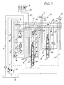
- FIG. 1 is a block diagram of the hydraulic control device with symbolically indicated consumers.
- the hydraulic control device S is supplied by a control pump R via a pressure line 10 with pressure medium.
- the control pump has a control connection 1, which is acted upon by a load pressure line branch 17 with control pressure to regulate the control pump as needed.
- an input block 2 is provided, which is combined with an intermediate block 3 and a direction selection control valve 4 in a convenient manner (block design), with further parallel-connected directional control valves 5, 5 '), for example, in series, to the operating mode directional control valve 4 and the intermediate block 3 are grown.
- the operating mode direction control valve 4 is formed with blocking zero position (as shown) and connected to the pressure line 10 and a tank line 11.
- a plurality of consumers 6 are connected via a line 31, either directly or via dashed lines indicated direction control valves 32, and via a further line 35 in parallel the directional control valves 5, 5 ', which define at least one directional control valve group, namely for consumers 7, 8, for example, power tools of a machine or a device.
- the consumers 6 are for example cylinders for supports.
- a drain valve 12 which operates in the manner of a pressure compensator and the pressure line 10 connects either to the tank line 11 or blocks this connection.
- the drain valve 12 is e.g. a control valve, which is acted upon in the up direction by a pilot pressure from the pump line 10 and in the feed direction of a control spring and a pilot pressure from a pilot line 38, which branches off from the pressure line 10 and leads to a pilot pressure-reducing valve 16, for example, a reduced pressure for hydraulic pilot controls the operating mode direction control valve 4 and also the other directional control valves 5, 5 'sets.
- a hydraulic damping device 14 for the load pressure line branch 17 and a pressure relief valve to the tank line 11 are included in the input block 2, as well as a main pressure relief valve 13 between the pressure line 10 and the tank line 11. Further, in the input block 2, a part 18 of the load pressure line branch 17 to the control connection 1 included.
- the part 18 of the load pressure line branch 17 is connected to a load pressure line 19, which comes from a switching valve V, which serves to set in the switching position shown an operation with a substantially constant supply form.
- the switching valve V is designed according to the invention as a hydraulically and pressure-dependent operable 3/2-way switching valve.
- the 3/2-way switching valve 29 is held by a spring 30 in the switching position shown, in which there is a Lastyakabgriff 20 of the operating mode direction control valve 4 via a control pressure line 21 connects to the load pressure line 19.
- the pilot control pressure reported to the 3/2-way switching valve 29 in the load pressure discharge 19 is limited by a pilot pressure limiting valve D.
- a control pressure line 28 of a load pressure signaling or LS system is also connected, which comes from Lastabgriffen 25 of the other directional control valves 5, 5 'and changeover valves 27 contains, to transmit the highest load pressure.
- the load pressure tap 25, for example, the directional control valve 5 is connected via a control pressure line 26 to the shuttle valve 27.
- the force of the spring 30, which holds the 3/2-way switching valve 29 in the switching position shown (constant supply form) is set to a certain load pressure limit below which is not switched.
- the line 31 is connected to the consumers 6, while the other output via a line 35 to the pressure sides of the further directional control valves 5, 5 'leads.
- control pump R is driven and the directional control valves 4, 5, 5 'are in their zero positions, optionally supplied by the control pump base pressure discharged via the drain valve 12 from the pressure line 10 into the tank line 11. There is no significant system pressure.
- the operating mode direction control valve 4 is switched to its switching position b (by proportional solenoid with hydraulic pilot control, as indicated), so that the pressure line 10 is connected to the line 31, while the pressure line 35 is relieved.
- the load pressure is tapped and reported via the passage 24 to the load pressure tap 20, and further brought over the control pressure line 21 to the 3/2-way switching valve 29, which is held by the spring 30 in the switching position shown.
- This pilot pressure can only reach the limit set at the load pressure limiting valve D. For example, corresponding to a supply pressure between 250 to 300 bar.
- This pilot pressure is transmitted via the pilot control line 19 through the input block 2 and the load pressure line branch 18, 17 to the control connection 1 of the control pump R.
- the control pump R pivots up, for example, to the maximum pressure, and then back to adjust the supply pressure. Since the passage 22 is shut off, pressure builds on the closing control side of the drain valve 12 via the load pressure line 38, which keeps the drain valve 12 closed.
- the substantially constant supply pre-pressure for example 250 to 300 bar, is used in the line 31 for actuating the consumer 6, optionally with variable amount, possibly by means of the directional control valves 32.
- the further directional control valves 5, 5 ' still receive no pressure.
- the hydraulic damping device 14 damps any pressure fluctuations of the pilot or load pressure.
- the pilot pressure reducing valve 16 adjusts the desired pilot pressure for the operational direction control valve 4, as well as the other directional control valves 5, 5 '.
- the load pressure limiting valve D limits, so to speak, the supply pre-pressure to the desired value, so that in this operation, the main pressure relief valve 13 does not need to address, because the control pump delivers only one supply form, which is lower than the set at the main pressure relief valve 13 pressure limit.
- the directional control valve 5 (or 5 ') adjusted in one of its switching positions a or b, then the build-up load pressure at the Last Kunststoffabgriff 25 is tapped and brought over the control pressure line 26 and the shuttle valve 27 and the control pressure line 28 to the 2/3-way switching valve 29 , Only when the tapped load pressure exceeds the limit determined by the spring 30, the 3/2-way switching valve 29 is switched to its other switching position, so that the load pressure from the load pressure line 28 via the load pressure line 19 and on to the control port 1 is reported.
- the control pump R now works with a variable supply pressure, which depends on the load pressure reported at the control connection 1. As long as the operating mode direction control valve 4 is in the switching position a, therefore, the consumers 7, 8 can be properly controlled (LS control).
- the drain valve 12 When operating with a variable supply pressure, the drain valve 12 may also be regulated as a function of the load pressure in the control pressure line 38 and the opening pilot pressure reported from the pressure line 10.
- the 3/2-way switching valve 29 is provided with the load pressure limiting valve D expediently in the intermediate block 3, which fits to the other components of the hydraulic control device. Alternatively, it would also be possible to integrate the 3/2-way switching valve 29 and the load pressure limiting valve D directly into the operating mode-way control valve 4, or to place it at the control connection 1.
Abstract
Description
Die Erfindung betrifft eine hydraulische Steuervorrichtung gemäß Oberbegriff des Patentanspruchs 1.The invention relates to a hydraulic control device according to the preamble of patent claim 1.
Bei einer aus der Praxis bekannten hydraulischen Steuervorrichtung für ein Forstarbeitsfahrzeug ist das Schaltventil ein 2/2-Magnetschaltventil, das zwischen dem Auslass der Regelpumpe und dem Lastdruckleitungszweig im Eingangsblock angeordnet ist. Zwischen dem Magnetschaltventil und dem Lastdruckleitungszweig verbindet ein Wechselventil druckabhängig entweder den Lastdruckleitungszweig oder den Ausgang des Magnetschaltventils mit dem Regelanschluss (Kurzschluss-Schaltung). Das Magnetschaltventil dient zum Erzielen eines Schaltzeitgewinns, der zweckmäßig sein kann, wenn wenn sehr lange Leitungen zu den Wegesteuerventilen bzw. den Verbrauchern vorliegen, die das Ansprechen verzögern, ein Wegesteuerventil ausgelenkt wird. Ferner können sich dann Druckeinbrüche oder Druckschläge im System einstellen Deshalb wird, ehe ein Verbraucher betrieben wird, die Regelpumpe hochgefahren und das Magnetschaltventil auf Durchgang geschaltet, so dass sich aus dem Pumpenversorgungsdruck Steuerdruck am Regelanschluss aufbaut. Die Regelpumpe geht zunächst auf Maximaldruck und regelt dann selbsttätig zurück. Da zu diesem Zeitpunkt kein Lastdruck im Lastdruckmeldesystem herrscht, sperrt das Ablassventil und fördert die Regelpumpe ggfs. gegen ein Sicherheitsventil, so dass ein sich zumindest im Wesentlichen konstanter Vordruck beispielsweise von etwa 250 Bar einstellt. Sobald dann ein Wegesteuerventil ausgelenkt ist, wird dieser Verbraucher zunächst mit dem Vordruck versorgt, wobei auch im Lastdruckmeldesystem ein Lastdruck entsteht, der bei Erreichen einer gewissen Höhe entweder das Wechselventil betätigt und den Lastdruckleitungszweig wieder mit dem Regelanschluss verbindet, und das Magnetschaltventil abkoppelt, oder es wird dann das Magnetschaltventil wieder in die Absperrstellung verstellt, damit der Lastdruck zum Regelanschluss gelangt. Dann erfolgt der Betrieb mit variablem Druck der Regelpumpe, gegebenenfalls sogar unter dem Einfluss des regelnden Ablassventils.In a hydraulic control device for a forestry work vehicle known from practice, the switching valve is a 2/2-solenoid switching valve, which is arranged between the outlet of the control pump and the load pressure line branch in the input block. Between the magnetic switching valve and the load pressure line branch, a change-over valve connects either the load pressure line branch or the output of the magnetic switching valve to the control connection (short circuit) in a pressure-dependent manner. The solenoid switching valve serves to achieve a switching time gain which may be useful when there is a very long line to the directional control valves or the consumers delaying the response, a directional control valve is deflected. Furthermore, then pressure drops or pressure surges can set in the system Therefore, before a consumer is operated, the control pump started up and the solenoid switching valve switched to passage, so that builds from the pump supply pressure control pressure at the control connection. The control pump initially goes to maximum pressure and then regulates automatically back. Since no load pressure prevails in the load pressure reporting system at this point in time, the discharge valve blocks and, if necessary, delivers the control pump to a safety valve, so that an at least substantially constant admission pressure is set, for example, about 250 bar. Once then a directional control valve is deflected, this consumer is initially supplied with the form, which also creates a load pressure in the load pressure detection system, which when reaching a certain height either actuates the shuttle valve and the load pressure line branch again connects to the control port, and disengages the solenoid valve, or it Then the solenoid valve is moved back to the shut-off, so that the load pressure reaches the control port. Then, the operation is carried out with variable pressure of the control pump, possibly even under the influence of the regulating drain valve.
Im Betrieb mit dem im Wesentlichen konstantem Vordruck werden beispielsweise die Stützen des Fahrzeugs ausgefahren, wobei dann keine andere Arbeitswerkzeuge treibenden Verbraucher betrieben werden, bis sich die Stützen das Fahrzeug ordnungsgemäß stabilisiert haben. Das Magnetschaltventil und seine Verschaltung bedeuten einen unerwünschten Mehraufwand und latente Störungsquellen.In operation with the substantially constant form, for example, the supports of the vehicle are extended, in which case no other working tools driving consumers until the supports have properly stabilized the vehicle. The solenoid valve and its interconnection represent an undesirable overhead and latent sources of interference.
Der Erfindung liegt die Aufgabe zugrunde, eine hydraulische Steuervorrichtung der eingangs genannten Art anzugeben, die trotz eines Schaltzeitgewinns baulich einfacher und kostengünstiger als die bekannte ist.The invention has for its object to provide a hydraulic control device of the type mentioned, which is structurally easier and cheaper than the known despite a Schaltzeitgewinns.
Die gestellte Aufgabe wird mit den Merkmalen des Patentanspruchs 1 gelöst.The stated object is achieved with the features of claim 1.
Das zum Erzielen eines Schaltzeitgewinns hydraulisch druckabhängig umstellbare 3/2-Wegeschaltventil ist baulich einfach, kompakt und funktionssicher. Es benötigt keine elektrische Verschaltung, und braucht nur eine relativ geringe Steuermenge zu verarbeiten, wodurch die Steuervorrichtung kostengünstiger wird.To achieve a Schaltzeitgewinns hydraulically pressure-
Zweckmäßig wird ein eigenes Betriebswahl-Wegesteuerventil in die Steuervorrichtung integriert, um eine Vorauswahl zwischen unterschiedlichen Verbrauchergruppen treffen zu können, deren jede mindestens einen Verbraucher umfasst und unabhängig von der anderen Gruppe gesteuert wird. Es erfolgt zunächst der Betrieb mit im Wesentlichen konstantem Versorgungs-Vordruck, um Schaltzeitverzögerungen mit den damit verbundenen Nachteile zu vermeiden, sobald ein Verbraucher zu bewegen ist. Das Betriebswahl-Wegesteuerventil bietet ferner den Vorteil, erst bei Betätigung die Regelpumpe vor der tatsächlichen Steuerung eines Verbrauchers hochzuregeln, um den Versorgungs-Vordruck einzustellen. Dies ist besonders zweckmäßig in einem Anwendungsfall, in welchem beispielsweise Stützen eines Fahrzeugs betätigt werden müssen. Hierfür muss, den Vorschriften entsprechend, ein Bediener mit Augenkontakt jede Stütze für sich ausfahren, was er beispielsweise mit einem Wegesteuerventil in oder an dem Stützenzylinder mit Blick auf die Stütze vornimmt. Von den anderen, Arbeitswerkzeuge antreibenden Verbrauchern wird keiner gesteuert. Erst wenn die Stützen ordnungsgemäß ausgefahren und verankert sind, wird das Betriebswahl-Wegesteuerventil in die andere Steuerstellung umgestellt, um dann die Arbeitswerkzeuge bei abgestütztem Fahrzeug bewegen zu können, jedoch anfänglich wiederum mit dem im Wesentlichen konstanten Versorgungs-Vordruck und einer variablen Menge, die über das jeweilige Wegesteuerventil gesteuert wird, bis ausreichender Lastdruck gemeldet ist.A separate operating mode direction control valve is expediently integrated into the control device in order to be able to make a preselection between different consumer groups, each of which comprises at least one consumer and is controlled independently of the other group. Initially, the operation is carried out with a substantially constant supply form, in order to avoid switching time delays with the associated disadvantages as soon as a consumer is to be moved. The mode selector control valve also has the advantage of only upshifting the control pump prior to actual control of a consumer to adjust the supply pre-pressure. This is particularly useful in an application in which, for example, supports of a vehicle must be operated. For this purpose, according to the regulations, an operator with eye contact has to extend each support for himself, which he does for example with a directional control valve in or on the support cylinder with a view of the support. None of the other consumers driving tools is controlled. Only when the supports are properly extended and anchored is the operating mode directional control valve changed over to the other control position in order to be able to move the working tools when the vehicle is supported, but initially again with the substantially constant supply pre-pressure and a variable amount. which is controlled via the respective directional control valve until sufficient load pressure is reported.
Bei einer besonders zweckmäßigen Ausführungsform ist das 3/2-Wegeschaltventil funktionell dem Betriebswahl-Wegesteuerventil zugeordnet, das selektiv entscheidet, welche der ausschließlich betreibbaren Verbraucher gesteuert werden. Sobald das Betriebswahl-Wegelsteuerventil aus der Nullstellung in eine Schaltstellung ausgelenkt ist, wird automatisch über das 3/2-Wegeschaltventil Vorsteuerdruck über den Vorsteuerdruckleitungszweig am Regelanschluss angelegt, um die Regelpumpe hochzuschwenken bzw. entsprechend einzuregeln, so dass für den Betrieb der ausgewählten Verbraucher im Wesentlichen konstanter Versorgungs-Vordruck ansteht. Erst wenn der Lastdruck von einem Lastdruckabgriff eines der Wegesteuerventile so weit angestiegen ist, dass er die Kraft der Feder des 3/2-Wege-Schaltventils überwindet, schaltet dieses um, um diesen Lastdruck an den Regelanschluss der Regelpumpe zu übertragen, so dass diese dann variablen Versorgungsdruck liefert.In a particularly advantageous embodiment, the 3/2-way switching valve is operatively associated with the operating mode directional control valve which selectively decides which of the exclusively operable consumers are controlled. As soon as the operating mode selector control valve is deflected from the zero position into a switching position, pilot pressure is automatically applied via the 3/2-way switching valve to the control connection via the pilot pressure line branch in order to raise or regulate the control pump, so that substantially constant supply form is pending. Only when the load pressure of a Lastdruckabgriff one of the directional control valves has risen so far that it overcomes the force of the spring of the 3/2-way switching valve, this switches to transfer this load pressure to the control connection of the control pump, so that then variable supply pressure supplies.
Die Verbraucher, die ohnedies bei konstantem Versorgungs-Vordruck betrieben werden, können gegebenenfalls sogar direkt an das Betriebswahl-Wegesteuerventil angeschlossen sein. Zweckmäßig sind jedoch für diese Verbraucher ebenfalls Wegesteuerventile vorgesehen.The consumers, which are operated anyway at constant supply form, may optionally even be connected directly to the operating mode directional control valve. Appropriately, however, directional control valves are also provided for these consumers.
Um zu vermeiden, dass nach einem Betriebsende oder durch Leckage Lastdruck eingesperrt bleibt oder sich aufbaut, ist es zweckmäßig, wenn die jeweiligen Lastdruckabgriffe zum Tank entlastet sind.In order to avoid that after an end of operation or leakage load pressure remains trapped or builds up, it is expedient if the respective load pressure taps are relieved to the tank.
Ein weiterer wichtiger Gedanke besteht darin, zwischen dem Lastdruckabgriff des Betriebswahl-Wegesteuerventils und dem 3/2-Wegeschaltventil ein Lastdruckbegrenzungsventil anzuordnen, das den Lastdruck zum Hochregeln der Regelpumpe im Hinblick auf den gewünschten, konstanten Versorgungs-Vordruck begrenzt. Selbst wenn sich über die Betätigung des Betriebswahl-Wegesteuerventils an dessen Lastabgriff aus irgendwelchen Gründen ein höherer Lastdruck ergeben sollte, ist dank des Lastdruck-Begrenzungsventils dafür Sorge getragen, dass der Regelanschluss der Regelpumpe den für den gewünschten Vordruck begrenzten Lastdruck erhält.Another important idea is to place between the load pressure tap of the operating mode directional control valve and the 3/2-way switching valve, a load pressure limiting valve which limits the load pressure for up-regulating the control pump in view of the desired, constant supply form. Even if the operation of the operating mode direction control valve at its load tap should result in a higher load pressure for any reason, thanks to the load pressure limiting valve, care is taken that the control connection of the control pump receives the load pressure limited to the desired admission pressure.
Ferner ist es günstig, wenn die Kraft der Feder des 3/2-Wege-Schaltventils auf eine ausgewählte Lastdruckgrenze eingestellt ist, so dass erst dann der Lastdruck an den Regelanschluss der Regelpumpe gemeldet wird, wenn er einen vorbestimmten Wert erreicht.Further, it is advantageous if the force of the spring of the 3/2-way switching valve is set to a selected load pressure limit, so that only then the load pressure is reported to the control connection of the control pump when it reaches a predetermined value.
Um ein zügiges Schalten des 3/2-Wegeschaltventils sicherzustellen, sollte die Federseite zum Tank entlastet sein.To ensure a smooth switching of the 3/2-way switching valve, the spring side should be relieved to the tank.
Gewinnbringend wird die Steuervorrichtung in ein Spezialfahrzeug integriert, das Stützen aufweist, für die zum Ausfahren der konstante Versorgungsvordruck ausreicht.Beneficially, the control device is integrated into a special vehicle which has supports for which the constant supply pressure is sufficient for extension.
Günstig ist es ferner, wenn das Betriebswahl-Wegesteuerventil mit blockierender Nullstellung ausgebildet ist, d.h. die Hauptverbindungen in der Druckleitung und der Tankleitung in der Nullstellung absperrt.It is also advantageous if the operating mode directional control valve is designed with a blocking neutral position, i. shuts off the main connections in the pressure line and the tank line in the zero position.
Baulich einfach wird das 3/2-Wegeschaltventil zusammen mit dem Lastdruck-Begrenzungsventil in einem Zwischenblock untergebracht, der an das Betriebswahl-Wegesteuerventil und den Eingangsblock angesetzt oder dazwischen eingesetzt ist.Structurally simple, the 3/2-way switching valve is housed together with the load pressure limiting valve in an intermediate block which is attached to the operating mode directional control valve and the input block or inserted therebetween.
Anhand der Zeichnung wird eine Ausführungsform des Erfindungsgegenstandes erläutert. Die Zeichnung in Fig. 1 ein Blockschaltbild der hydraulischen Steuervorrichtung mit symbolisch angedeuteten Verbrauchern.Reference to the drawings, an embodiment of the subject invention will be explained. The drawing in Fig. 1 is a block diagram of the hydraulic control device with symbolically indicated consumers.
Die hydraulische Steuervorrichtung S wird von einer Regelpumpe R über eine Druckleitung 10 mit Druckmittel versorgt. Die Regelpumpe verfügt über einen Regelanschluss 1, der über einen Lastdruckleitungszweig 17 mit Steuerdruck beaufschlagbar wird, um die Regelpumpe bedarfsabhängig zu regeln.The hydraulic control device S is supplied by a control pump R via a
In der Steuervorrichtung S ist ein Eingangsblock 2 vorgesehen, der mit einem Zwischenblock 3 und einem Betriebswahl-Wegesteuerventil 4 in zweckmäßiger Weise vereinigt ist (Blockbauweise), wobei weitere parallel geschaltete Wegesteuerventile 5, 5'), beispielsweise in Reihe, an das Betriebswahl-Wegesteuerventil 4 und den Zwischenblock 3 angebaut sind. Das Betriebswahl-Wegesteuerventil 4 ist mit blockierender Nullstellung (wie gezeigt) ausgebildet und an die Druckleitung 10 sowie eine Tankleitung 11 angeschlossen.In the control device S, an
An das Betriebswahl-Wegsteuerventil 4 sind über eine Leitung 31 mehrere Verbraucher 6 angeschlossen, entweder direkt, oder über gestrichelt angedeutete Wegesteuerventile 32, und über eine weitere Leitung 35 parallel die Wegesteuerventile 5, 5', die wenigstens eine Wegesteuerventil-Gruppe definieren, und zwar für Verbraucher 7, 8, die beispielsweise Arbeitswerkzeuge einer Maschine oder eines Geräts antreiben. Die Verbraucher 6 sind beispielsweise Zylinder für Stützen.To the operating mode travel control valve 4 a plurality of consumers 6 are connected via a
Im Eingangssteuerblock 2 ist ein Ablassventil 12 enthalten, das nach Art einer Druckwaage arbeitet und die Druckleitung 10 entweder mit der Tankleitung 11 verbindet oder diese Verbindung blockiert. Das Ablassventil 12 ist z.B. ein Regelventil, das in Aufsteuerrichtung von einem Vorsteuerdruck aus der Pumpenleitung 10 und in Zusteuerrichtung von einer Regelfeder und einem Vorsteuerdruck aus einer Vorsteuerleitung 38 beaufschlagt wird, die von der Druckleitung 10 abzweigt und zu einem Vorsteuerdruck-Minderventil 16 führt, das beispielsweise einen geminderten Druck für hydraulische Vorsteuerungen des Betriebswahl-Wegesteuerventils 4 und auch der anderen Wegesteuerventile 5, 5' einstellt. Ferner sind im Eingangsblock 2 eine hydraulische Dämpfvorrichtung 14 für den Lastdruckleitungszweig 17 und ein Druckbegrenzungsventil zur Tankleitung 11 enthalten, wie auch ein Haupt-Druckbegrenzungsventil 13 zwischen der Druckleitung 10 und der Tankleitung 11. Ferner ist im Eingangsblock 2 ein Teil 18 des Lastdruckleitungszweiges 17 zum Regelanschluss 1 enthalten.In the
Der Teil 18 des Lastdruckleitungszweiges 17 ist an eine Lastdruckleitung 19 angeschlossen, die von einem Schaltventil V kommt, das dazu dient, in der gezeigten Schaltstellung einen Betrieb mit im Wesentlichen konstantem Versorgungs-Vordruck einzustellen. Das Schaltventil V ist erfindungsgemäß als hydraulisch und druckabhängig betätigbares 3/2-Wegeschaltventil ausgebildet. Das 3/2-Wegeschaltventil 29 wird durch eine Feder 30 in der gezeigten Schaltstellung gehalten, in der es einen Lastdruckabgriff 20 des Betriebswahl-Wegesteuerventils 4 über eine Steuerdruckleitung 21 mit der Lastdruckleitung 19 verbindet. Der an das 3/2-Wegeschaltventil 29 in der Lastdruckableitung 19 gemeldete Vorsteuerdruck wird durch ein Vorsteuerdruck-Begrenzungsventil D begrenzt. An das 3/2-Wegeschaltventil 29 ist ferner eine Steuerdruckleitung 28 eines Lastdruckmelde- oder LS-Systems angeschlossen, die von Lastabgriffen 25 der weiteren Wegesteuerventile 5, 5' kommt und Wechselventile 27 enthält, um den jeweils höchsten Lastdruck zu übermitteln. Der Lastdruckabgriff 25 beispielsweise des Wegesteuerventils 5 ist über eine Steuerdruckleitung 26 mit dem Wechselventil 27 verbunden.The part 18 of the load
Die Kraft der Feder 30, die das 3/2-Wegeschaltventil 29 in der gezeigten Schaltstellung (konstanter Versorgungs-Vordruck) hält, ist auf eine bestimmte Lastdruckgrenze eingestellt, unterhalb der nicht umgeschaltet wird.The force of the spring 30, which holds the 3/2-
An den einen Ausgang des Betriebswahl-Wegesteuerventils 4 ist die Leitung 31 zu den Verbrauchern 6 angeschlossen, während der andere Ausgang über eine Leitung 35 zu den Druckseiten der weiteren Wegesteuerventile 5, 5' führt.At one output of the operating mode direction control valve 4, the
In der gezeigten Nullstellung des Betriebswahl-Wegesteuerventils 4 wird dessen Lastdruckabgriff 20 über einen Durchgang 36 zum Tank entlastet. Ferner wird in der Schaltstellung b über einen Durchgang 22 der Vorsteuerdruck für das Ablassventil 12 zum Tank entlastet. Schließlich wird der jeweilige Lastdruck in der Leitung 31 oder 35 abhängig von der Schaltstellung des Betriebswahl-Wegesteuerventils 4 über Durchgänge 24 bzw. 23 zum Lastdruckabgriff 20 gebracht. In der Nullstellung des Betriebswahl-Wegesteuerventils 4 ist der Lastdruckabgriff 20 über den Durchgang 36 zum Tank entlastet. Ähnlich sind auch in den weiteren Wegesteuerventilen 5, 5' Durchgänge 37 vorgesehen, um in der Nullstellung den Lastdruckabgriff 25 zum Tank zu entlasten. An jedem weiteren Wegesteuerventil 5 5' sind die Verbraucher 7, 8 an Leitungen 33, 34 angeschlossen.In the illustrated zero position of the operating mode direction control valve 4 whose Lastdruckabgriff 20 is relieved via a
Sobald die Regelpumpe R angetrieben wird und die Wegesteuerventile 4, 5, 5' in ihren Nullstellungen sind, wird gegebenenfalls von der Regelpumpe gelieferter Grunddruck über das Ablassventil 12 aus der Druckleitung 10 in die Tankleitung 11 abgelassen. Es liegt kein nennenswerter Systemdruck vor.Once the control pump R is driven and the directional control valves 4, 5, 5 'are in their zero positions, optionally supplied by the control pump base pressure discharged via the
Sofern die Verbraucher 6 zu steuern sind, wird das Betriebswahl-Wegesteuerventil 4 in seine Schaltstellung b umgestellt (durch Proportionalmagneten mit hydraulischer Vorsteuerung, wie angedeutet), so dass die Druckleitung 10 mit der Leitung 31 verbunden ist, während die Druckleitung 35 entlastet wird. Aus der Leitung 31 wird der Lastdruck abgegriffen und über den Durchgang 24 zum Lastdruckabgriff 20 gemeldet, und weiter über die Steuerdruckleitung 21 zum 3/2-Wegeschaltventil 29 gebracht, das durch die Feder 30 in der gezeigten Schaltstellung gehalten wird. Dieser Vorsteuerdruck kann nur die am Lastdruck-Begrenzungsventil D eingestellte Grenze erreichen. Z.B. entsprechend einem Versorgungs-vordruck zwischen 250 bis 300 Bar. Dieser Vorsteuerdruck wird über die Vorsteuerleitung 19 durch den Eingangsblock 2 und den Lastdruckleitungszweig 18, 17 an den Regelanschluss 1 der Regelpumpe R übertragen. Die Regelpumpe R schwenkt hoch, beispielsweise bis zum Maximaldruck, und dann wieder zurück, um den Versorgungsvordruck einzustellen. Da der Durchgang 22 abgesperrt ist, baut sich auf der Schließsteuerseite des Ablassventils 12 über die Lastdruckleitung 38 Steuerdruck auf, der das Ablassventil 12 geschlossen hält.If the consumers 6 are to be controlled, the operating mode direction control valve 4 is switched to its switching position b (by proportional solenoid with hydraulic pilot control, as indicated), so that the
Der im Wesentlichen konstante Versorgungs-Vordruck, beispielsweise 250 bis 300 Bar, wird in der Leitung 31 zum Betätigen der Verbraucher 6, gegebenenfalls mit variabler Menge, benutzt, gegebenenfalls mittels der Wegesteuerventile 32. Die weiteren Wegesteuerventile 5, 5' erhalten noch keinen Druck. Die hydraulische Dämpfungsvorrichtung 14 dämpft eventuelle Druckschwankungen des Vorsteuer- oder Lastdrucks. Das Vorsteuerdruckminderventil 16 stellt den gewünschten Vorsteuerdruck für das Betriebswahl-Wegesteuerventil 4, und auch die anderen Wegesteuerventile 5, 5' ein. Sobald die Verbraucher 6 ausgefahren sind, beispielsweise um Stützen zu postionieren, wird das Betriebswahl-Wegesteuerventil 4 in die anderen Schaltstellung a umgestellt, um nun auch Werkzeuge betreiben zu können, die mittels der Verbraucher 7, 8 gesteuert werden. Dies bedeutet, dass die Leitung 31 drucklos wird, während die Leitung 35 den Versorgungs-Vordruck erhält. Das Lastdruck-Begrenzungsventil D begrenzt sozusagen den Versorgungs-Vordruck auf den gewünschten Wert, so dass in diesem Betrieb das Haupt-Druckbegrenzungsventil 13 nicht anzusprechen braucht, weil die Regelpumpe nur einen Versorgungs-Vordruck liefert, der niedriger ist als der am Haupt-Druckbegrenzungsventil 13 eingestellte Druckgrenzwert.The substantially constant supply pre-pressure, for example 250 to 300 bar, is used in the
Wird nun das Wegesteuerventil 5 (oder 5') in eine seiner Schaltstellungen a oder b verstellt, dann wird der sich aufbauende Lastdruck am Lastdruckabgriff 25 abgegriffen und über die Steuerdruckleitung 26 und das Wechselventil 27 sowie die Steuerdruckleitung 28 zum 2/3-Wegeschaltventil 29 gebracht. Erst wenn der abgegriffene Lastdruck die von der Feder 30 bestimmte Grenze überschreitet, wird das 3/2-Wegeschaltventil 29 in seine andere Schaltstellung umgestellt, so dass der Lastdruck aus der Lastdruckleitung 28 über die Lastdruckleitung 19 und weiter zum Regelanschluss 1 gemeldet wird. Die Regelpumpe R arbeitet nun mit variablem Versorgungsdruck, der sich nach dem am Regelanschluss 1 gemeldeten Lastdruck richtet. Solange das Betriebswahl-Wegesteuerventil 4 in der Schaltstellung a ist, können demzufolge die Verbraucher 7, 8 einwandfrei gesteuert werden (LS-Regelung).If now the directional control valve 5 (or 5 ') adjusted in one of its switching positions a or b, then the build-up load pressure at the
Im Betrieb mit variablem Versorgungsdruck regelt gegebenenfalls auch das Ablassventil 12 abhängig vom Lastdruck in der Steuerdruckleitung 38 und dem aus der Druckleitung 10 gemeldeten Öffnungs-Vorsteuerdruck.When operating with a variable supply pressure, the
Das 3/2-Wege-Schaltventil 29 ist mit dem Lastdruck-Begrenzungsventil D zweckmäßig in dem Zwischenblock 3 vorgesehen, der zu den anderen Komponenten der hydraulischen Steuervorrichtung passt. Alternativ wäre es aber auch möglich, das 3/2-Wegeschaltventil 29 und das Lastdruck-Begrenzungsventil D in das Betriebswahl-Wege-Steuerventil 4 direkt einzugliedern, oder beim Regelanschluss 1 zu platzieren.The 3/2-
Claims (11)
Priority Applications (3)
| Application Number | Priority Date | Filing Date | Title |
|---|---|---|---|
| EP20060005669 EP1837529B1 (en) | 2006-03-20 | 2006-03-20 | Hydraulic control device |
| ES06005669T ES2314768T3 (en) | 2006-03-20 | 2006-03-20 | HYDRAULIC CONTROL DEVICE. |
| DE200650001885 DE502006001885D1 (en) | 2006-03-20 | 2006-03-20 | Hydraulic control device |
Applications Claiming Priority (1)
| Application Number | Priority Date | Filing Date | Title |
|---|---|---|---|
| EP20060005669 EP1837529B1 (en) | 2006-03-20 | 2006-03-20 | Hydraulic control device |
Publications (2)
| Publication Number | Publication Date |
|---|---|
| EP1837529A1 true EP1837529A1 (en) | 2007-09-26 |
| EP1837529B1 EP1837529B1 (en) | 2008-10-22 |
Family
ID=36763596
Family Applications (1)
| Application Number | Title | Priority Date | Filing Date |
|---|---|---|---|
| EP20060005669 Expired - Fee Related EP1837529B1 (en) | 2006-03-20 | 2006-03-20 | Hydraulic control device |
Country Status (3)
| Country | Link |
|---|---|
| EP (1) | EP1837529B1 (en) |
| DE (1) | DE502006001885D1 (en) |
| ES (1) | ES2314768T3 (en) |
Cited By (2)
| Publication number | Priority date | Publication date | Assignee | Title |
|---|---|---|---|---|
| EP3093505A1 (en) | 2015-05-11 | 2016-11-16 | HAWE Hydraulik SE | Hydraulic control device and selector valve |
| DE102020209387B3 (en) | 2020-07-24 | 2021-07-15 | Hawe Hydraulik Se | Preselection valve, hydraulic valve bank and hydraulic control device |
Citations (2)
| Publication number | Priority date | Publication date | Assignee | Title |
|---|---|---|---|---|
| EP1088995A1 (en) * | 1999-04-26 | 2001-04-04 | Hitachi Construction Machinery Co., Ltd. | Hydraulic circuit device |
| EP1164297A1 (en) * | 2000-01-25 | 2001-12-19 | Hitachi Construction Machinery Co., Ltd. | Hydraulic driving device |
-
2006
- 2006-03-20 EP EP20060005669 patent/EP1837529B1/en not_active Expired - Fee Related
- 2006-03-20 ES ES06005669T patent/ES2314768T3/en active Active
- 2006-03-20 DE DE200650001885 patent/DE502006001885D1/en active Active
Patent Citations (2)
| Publication number | Priority date | Publication date | Assignee | Title |
|---|---|---|---|---|
| EP1088995A1 (en) * | 1999-04-26 | 2001-04-04 | Hitachi Construction Machinery Co., Ltd. | Hydraulic circuit device |
| EP1164297A1 (en) * | 2000-01-25 | 2001-12-19 | Hitachi Construction Machinery Co., Ltd. | Hydraulic driving device |
Cited By (3)
| Publication number | Priority date | Publication date | Assignee | Title |
|---|---|---|---|---|
| EP3093505A1 (en) | 2015-05-11 | 2016-11-16 | HAWE Hydraulik SE | Hydraulic control device and selector valve |
| DE102020209387B3 (en) | 2020-07-24 | 2021-07-15 | Hawe Hydraulik Se | Preselection valve, hydraulic valve bank and hydraulic control device |
| CN113969911A (en) * | 2020-07-24 | 2022-01-25 | 哈威液压股份公司 | Pre-selection valve, hydraulic valve assembly and hydraulic control unit |
Also Published As
| Publication number | Publication date |
|---|---|
| EP1837529B1 (en) | 2008-10-22 |
| ES2314768T3 (en) | 2009-03-16 |
| DE502006001885D1 (en) | 2008-12-04 |
Similar Documents
| Publication | Publication Date | Title |
|---|---|---|
| EP1092095B2 (en) | Hydraulic circuit | |
| EP1915538B1 (en) | Circuit for controlling a double-action hydraulic drive cylinder | |
| DE102013222954B4 (en) | Hydraulic drive device for a work machine | |
| EP1710445A2 (en) | Hydraulic control system | |
| DE4137963C2 (en) | Valve arrangement for load-independent control of several hydraulic consumers | |
| DE60304663T2 (en) | Hydraulic valve device | |
| EP2469103A2 (en) | Hydraulic motor | |
| DE4036720A1 (en) | CONTROL CIRCUIT FOR THE LOAD-INDEPENDENT DISTRIBUTION OF A PRESSURE FLOW | |
| CH700344B1 (en) | Control device for at least two hydraulic drives. | |
| EP0115590B1 (en) | Hydraulic control device | |
| EP2404493B1 (en) | Hoisting gear | |
| EP1837529B1 (en) | Hydraulic control device | |
| AT392606B (en) | HYDRAULIC CONTROL DEVICE FOR THE INJECTION UNIT OF A PLASTIC INJECTION MOLDING MACHINE | |
| EP3135924B1 (en) | Hydraulic device | |
| EP2466154B1 (en) | Electrohydraulic control device | |
| EP3398418A1 (en) | Hydraulic system of a machine usable in agriculture or civil engineering | |
| EP0297401B1 (en) | Hydraulic control device | |
| EP2157320B1 (en) | Hydraulic device for a hydro motor | |
| WO2005093263A1 (en) | Hydraulic control system | |
| DE19742157A1 (en) | Control device for an adjustable hydraulic pump with several consumers | |
| DE19709958A1 (en) | Hydrostatic drive system has outlet tube with variable-pressure threshold valve | |
| EP1574720B1 (en) | Electro-hydraulic control circuit and method of its deactivation | |
| DE4418881A1 (en) | Electrohydraulic control system and control valve for farm vehicle lifting gear | |
| DE2800814A1 (en) | Load compensated hydraulic control system - has pump adjusting mechanism connected to pilot valve discharging to tank | |
| EP3045723A1 (en) | Axial piston pump |
Legal Events
| Date | Code | Title | Description |
|---|---|---|---|
| PUAI | Public reference made under article 153(3) epc to a published international application that has entered the european phase |
Free format text: ORIGINAL CODE: 0009012 |
|
| 17P | Request for examination filed |
Effective date: 20070104 |
|
| AK | Designated contracting states |
Kind code of ref document: A1 Designated state(s): AT BE BG CH CY CZ DE DK EE ES FI FR GB GR HU IE IS IT LI LT LU LV MC NL PL PT RO SE SI SK TR |
|
| AX | Request for extension of the european patent |
Extension state: AL BA HR MK YU |
|
| GRAP | Despatch of communication of intention to grant a patent |
Free format text: ORIGINAL CODE: EPIDOSNIGR1 |
|
| GRAS | Grant fee paid |
Free format text: ORIGINAL CODE: EPIDOSNIGR3 |
|
| AKX | Designation fees paid |
Designated state(s): DE ES IT |
|
| GRAA | (expected) grant |
Free format text: ORIGINAL CODE: 0009210 |
|
| RAP1 | Party data changed (applicant data changed or rights of an application transferred) |
Owner name: HAWE HYDRAULIK GMBH & CO. KG Owner name: PUTZMEISTER CONCRETE PUMPS GMBH |
|
| AK | Designated contracting states |
Kind code of ref document: B1 Designated state(s): DE ES IT |
|
| REF | Corresponds to: |
Ref document number: 502006001885 Country of ref document: DE Date of ref document: 20081204 Kind code of ref document: P |
|
| REG | Reference to a national code |
Ref country code: ES Ref legal event code: FG2A Ref document number: 2314768 Country of ref document: ES Kind code of ref document: T3 |
|
| PGFP | Annual fee paid to national office [announced via postgrant information from national office to epo] |
Ref country code: ES Payment date: 20090325 Year of fee payment: 4 |
|
| PLBE | No opposition filed within time limit |
Free format text: ORIGINAL CODE: 0009261 |
|
| STAA | Information on the status of an ep patent application or granted ep patent |
Free format text: STATUS: NO OPPOSITION FILED WITHIN TIME LIMIT |
|
| 26N | No opposition filed |
Effective date: 20090723 |
|
| PGFP | Annual fee paid to national office [announced via postgrant information from national office to epo] |
Ref country code: IT Payment date: 20090331 Year of fee payment: 4 |
|
| PG25 | Lapsed in a contracting state [announced via postgrant information from national office to epo] |
Ref country code: IT Free format text: LAPSE BECAUSE OF NON-PAYMENT OF DUE FEES Effective date: 20100320 |
|
| REG | Reference to a national code |
Ref country code: ES Ref legal event code: FD2A Effective date: 20110418 |
|
| PG25 | Lapsed in a contracting state [announced via postgrant information from national office to epo] |
Ref country code: ES Free format text: LAPSE BECAUSE OF NON-PAYMENT OF DUE FEES Effective date: 20110404 |
|
| PG25 | Lapsed in a contracting state [announced via postgrant information from national office to epo] |
Ref country code: ES Free format text: LAPSE BECAUSE OF NON-PAYMENT OF DUE FEES Effective date: 20100321 |
|
| PGFP | Annual fee paid to national office [announced via postgrant information from national office to epo] |
Ref country code: DE Payment date: 20150327 Year of fee payment: 10 |
|
| REG | Reference to a national code |
Ref country code: DE Ref legal event code: R119 Ref document number: 502006001885 Country of ref document: DE |
|
| PG25 | Lapsed in a contracting state [announced via postgrant information from national office to epo] |
Ref country code: DE Free format text: LAPSE BECAUSE OF NON-PAYMENT OF DUE FEES Effective date: 20161001 |