EP1837270A2 - Bicycle saddle assembly - Google Patents
Bicycle saddle assembly Download PDFInfo
- Publication number
- EP1837270A2 EP1837270A2 EP06020945A EP06020945A EP1837270A2 EP 1837270 A2 EP1837270 A2 EP 1837270A2 EP 06020945 A EP06020945 A EP 06020945A EP 06020945 A EP06020945 A EP 06020945A EP 1837270 A2 EP1837270 A2 EP 1837270A2
- Authority
- EP
- European Patent Office
- Prior art keywords
- bicycle
- saddle assembly
- bicycle saddle
- saddle body
- saddle
- Prior art date
- Legal status (The legal status is an assumption and is not a legal conclusion. Google has not performed a legal analysis and makes no representation as to the accuracy of the status listed.)
- Granted
Links
Images


Classifications
-
- B—PERFORMING OPERATIONS; TRANSPORTING
- B62—LAND VEHICLES FOR TRAVELLING OTHERWISE THAN ON RAILS
- B62J—CYCLE SADDLES OR SEATS; AUXILIARY DEVICES OR ACCESSORIES SPECIALLY ADAPTED TO CYCLES AND NOT OTHERWISE PROVIDED FOR, e.g. ARTICLE CARRIERS OR CYCLE PROTECTORS
- B62J1/00—Saddles or other seats for cycles; Arrangement thereof; Component parts
- B62J1/002—Saddles having a seating area with a central cavity or depression
-
- B—PERFORMING OPERATIONS; TRANSPORTING
- B62—LAND VEHICLES FOR TRAVELLING OTHERWISE THAN ON RAILS
- B62J—CYCLE SADDLES OR SEATS; AUXILIARY DEVICES OR ACCESSORIES SPECIALLY ADAPTED TO CYCLES AND NOT OTHERWISE PROVIDED FOR, e.g. ARTICLE CARRIERS OR CYCLE PROTECTORS
- B62J1/00—Saddles or other seats for cycles; Arrangement thereof; Component parts
- B62J1/007—Saddles with specific anatomical adaptations
Definitions
- the present invention relates generally to bicycle saddles and more particularly to a bicycle saddle assembly that includes a saddle body having an opening space to arrange the rider's genital area and thereby at once reduces the pressure placed thereon and dissipates heat generated therein.
- Conventional bicycle seats or saddles are typically horizontal in profile with a narrow front end portion and a wider rear portion.
- the narrow front end portion creates a pressure zone on the perineal areas of the rider, which may adversely affect blood vessels and nerves and cause distress or injury to surrounding anatomical organs and tissues.
- U.S. Pat. No. 6,106,059 discloses a bicycle saddle having a front which broadens towards a rear that has a notched groove.
- the saddle body further includes a concave portion provided between the wider posterior portion and the narrow anterior portion.
- the saddle body has a highest area located on the wider posterior portion and a lowest area located on the concave portion so that an opening space with a sufficient depth is defined above the concave portion.
- the wider posterior portion of the saddle body has a supporting plate on which the highest area located.
- the concave portion has a base on which the lowest area located, a first inclined section which rises gradually from the lowest area to the supporting plate of the wider posterior portion, and a second inclined section which rises gradually from the lowest area to the narrow anterior portion so that an arc-shaped opening space with a sufficient depth can be formed above the concave portion.
- the saddle body has a mounting portion being U-shaped in transverse cross section and extending downwardly from the underneath side of the saddle body.
- the bicycle saddle assembly in accordance with the present invention further comprises a mounting means to cooperate with the mounting portion of the saddle body so that the saddle body can be easily mounted on a seat post of a bicycle.
- the mounting means may include an upper device and a lower device.
- the mounting portion of the saddle body defines an end part to cooperate with the upper device and the lower device to mount the saddle body on a seat post of a bicycle.
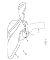
- Bicycle saddle assembly 10 includes a saddle body 12 and a mounting means14 to mount saddle body 12 on a seat post 1 of a bicycle.
- Saddle body 12 has a wider posterior portion 20 for supporting bicycle rider's buttocks, a narrow anterior portion 22 which fits between bicycle rider's crotch and a concave portion 24 located between wider posterior portion 20 and narrow anterior portion 22.
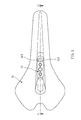
- Wider posterior portion 20 is a supporting plate with a pair of depressed upper surface 202, 204 respectively provided on either side of the center axis of the saddle body 12 so that the rider's buttocks can closely rest on wider posterior portion 20 (as shown in FIG. 8).
- Concave portion 24 has a base 240, a first slope section 242 extending upwardly from base 240 to one end of wider posterior portion 20, and a second slop section 244 extending upwardly from base 240 to one end of narrow anterior portion 22.
- first slop section 242 is longer than second slop section 244 so that base 240 can be located near narrow anterior portion 22.
- concave portion 24 has a pair of downwardly extending and symmetrically distributed sides 246, so that the rider's crotch can be comfortably fitted thereto (as shown in FIG. 7).
- Saddle body 12 has a highest area H positioned on wider posterior portion 20 and a lowest area L positioned on base 240.
- the difference D between highest area H and lowest area L varies from 30 mm to 60mm so as to form an arc-shaped opening space 30 with a sufficient depth above concave portion 24 to arrange rider's genitals (as shown in FIG. 9).
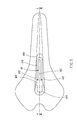
- the upper side of saddle body 12 provides a ventilation channel 26 extending along the center axis thereof.
- Mounting portion 40 Extending downwardly from the underneath side of saddle body 12 is a mounting portion 40.
- Mounting portion 40 has an rectangle upper opening 400, two side walls 402 extending respectively and downwardly from each long side of upper opening 400, a front wall 406, a rear opening 408, a rear reinforced edge 409 and a bottom wall 410 with a long cut 412.
- bottom wall 410 is horizontally provided so that each side wall 402 has a short front side 414 and a long rear side 416.
- long rear side 416' of each side wall 402' of mounting portion 40' has a cove 418' so that each side wall 402' will function as a buffer to absorb the shocks as riding.
- Mounting means 14 is designed to cooperate with mounting portion 40 of saddle body 12 so that saddle body 12 can be easily mounted on seat post 1 of a bicycle.
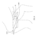
- Mounting means 14 includes an upper device 16 with at least a threaded hole 160 and an under device 18 with a center groove 180 and a long hole 182 (as shown in FIG. 2).
- upper device 16 is placed into the inside of mounting portion 40 from upper opening 400 and against the upper surface of bottom wall 410.
- Under device 18 is placed under the lower surface of bottom wall 410 in such a way that the end part of mounting portion 40 can be received in center groove 180 of under device 18.
- a prior art connecting device 2 is placed on the top end of seat post 1 to cooperate with under device 18 so that a bolt 3 can be inserted through a hole provided on seat post 1, long hole 182 of under device 18 and screwed into threaded hole 160 of upper device 16 to mount saddle body 12 on seat post 1.
- a mounting means 50 has an upper device 52 and an under device 54.
- Upper device 52 is designed to have a lengthwise trench 520, a long hole 522 and two crosswise trenches 524.
- Under device 54 is the same as mounting means 14.
- two short nuts 56 are used to be respectively received in each crosswise trench 524 and screwed into by a bolt.
- a long nut 58 is used to be received in lengthwise trench 520 and screwed into by a bolt.
Abstract
Description
- The present invention relates generally to bicycle saddles and more particularly to a bicycle saddle assembly that includes a saddle body having an opening space to arrange the rider's genital area and thereby at once reduces the pressure placed thereon and dissipates heat generated therein.
- Conventional bicycle seats or saddles are typically horizontal in profile with a narrow front end portion and a wider rear portion. The narrow front end portion creates a pressure zone on the perineal areas of the rider, which may adversely affect blood vessels and nerves and cause distress or injury to surrounding anatomical organs and tissues.
- To try to avoid the drawbacks described above,
U.S. Pat. No. 6,106,059 discloses a bicycle saddle having a front which broadens towards a rear that has a notched groove. In practical using, we can find that such a design can only relieve part of pressure placed on the perineal areas of the rider. Therefore, it is desirable to have a saddle with a construction that all of pressure placed on the perineal areas of the rider can be relieved. - It is the primary objective of the present invention to provide a bicycle saddle assembly with an opening space which can fully relieve pressure placed on the rider's perineal areas.
- It is a further objective of the present invention to provide a bicycle saddle assembly with ventilation function for dissipating heat generated in the rider's perineal areas as riding.
- In carrying out the foregoing objectives, a bicycle saddle assembly in accordance with the present invention comprises a saddle body including a wider posterior portion for supporting bicycle rider's buttocks and a narrow anterior portion which fits between bicycle rider's crotch. The saddle body further includes a concave portion provided between the wider posterior portion and the narrow anterior portion. The saddle body has a highest area located on the wider posterior portion and a lowest area located on the concave portion so that an opening space with a sufficient depth is defined above the concave portion. Whereby, as riding, bicycle riders can arrange his perineal areas comfortably on the saddle body to relieve pressure placed thereon and dissipate heat generated therein.
- In a preferred embodiment of the present invention, the wider posterior portion of the saddle body has a supporting plate on which the highest area located. The concave portion has a base on which the lowest area located, a first inclined section which rises gradually from the lowest area to the supporting plate of the wider posterior portion, and a second inclined section which rises gradually from the lowest area to the narrow anterior portion so that an arc-shaped opening space with a sufficient depth can be formed above the concave portion.
- In another preferred embodiment of the present invention, the saddle body has a mounting portion being U-shaped in transverse cross section and extending downwardly from the underneath side of the saddle body. The bicycle saddle assembly in accordance with the present invention further comprises a mounting means to cooperate with the mounting portion of the saddle body so that the saddle body can be easily mounted on a seat post of a bicycle.
- In a further preferred embodiment of the present invention, the mounting means may include an upper device and a lower device. The mounting portion of the saddle body defines an end part to cooperate with the upper device and the lower device to mount the saddle body on a seat post of a bicycle.
- The present invention may be more clearly understood with reference to the following detailed description, in conjunction with the appended drawings of which:
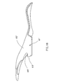
- FIG. 1 is a perspective view of a first preferred embodiment according to the present invention more clearly showing the saddle assembly mounting on a seat post of a bicycle;
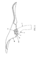
- FIG. 2 is an exploded view of the embodiment shown in FIG. 1;
- FIG. 3 is a top view of the embodiment shown in FIG. 1;
- FIG. 4 is a side view of the embodiment shown in FIG. 1;
- FIG. 5 is a top view of a saddle body of the embodiment shown in FIG. 1;
- FIG. 6 is a cross-sectional view taken along the line 6-6 of FIG. 5;
- FIG. 7 is a cross-sectional view taken along the line 7-7 of FIG. 6;
- FIG. 8 is a cross-sectional view taken along the line 8-8 of FIG. 6;
- FIG. 9 is a side view of the saddle body of the embodiment shown in FIG. 1 move clearly showing the ways of positioning the genital area in the case of a male rider;
- FIG. 10 is a side view of a saddle body of a second preferred embodiment according to the present invention;
- FIG. 11 is a cross-sectional view taken along the line 1-11 of FIG. 3;
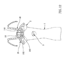
- FIG. 12 is a cross-sectional view taken along the line 12-12 of FIG. 4;
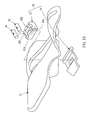
- FIG. 13 is an exploded view of a third preferred embodiment according to the present invention; and
- FIG. 14 is an exploded view of a fourth preferred embodiment according to the present invention.
- Referring now to FIGS. 1-12, there can be seen
bicycle saddle assembly 10 embodying the present invention.Bicycle saddle assembly 10 includes asaddle body 12 and a mounting means14 to mountsaddle body 12 on aseat post 1 of a bicycle.Saddle body 12 has a widerposterior portion 20 for supporting bicycle rider's buttocks, a narrowanterior portion 22 which fits between bicycle rider's crotch and aconcave portion 24 located between widerposterior portion 20 and narrowanterior portion 22. - Wider
posterior portion 20 is a supporting plate with a pair of depressedupper surface saddle body 12 so that the rider's buttocks can closely rest on wider posterior portion 20 (as shown in FIG. 8). -
Concave portion 24 has abase 240, afirst slope section 242 extending upwardly frombase 240 to one end of widerposterior portion 20, and asecond slop section 244 extending upwardly frombase 240 to one end of narrowanterior portion 22. In this embodiment,first slop section 242 is longer thansecond slop section 244 so thatbase 240 can be located near narrowanterior portion 22. Particularly,concave portion 24 has a pair of downwardly extending and symmetrically distributedsides 246, so that the rider's crotch can be comfortably fitted thereto (as shown in FIG. 7). -
Saddle body 12 has a highest area H positioned on widerposterior portion 20 and a lowest area L positioned onbase 240. The difference D between highest area H and lowest area L varies from 30 mm to 60mm so as to form an arc-shaped opening space 30 with a sufficient depth aboveconcave portion 24 to arrange rider's genitals (as shown in FIG. 9). In this embodiment, the upper side ofsaddle body 12 provides aventilation channel 26 extending along the center axis thereof. - Extending downwardly from the underneath side of
saddle body 12 is a mountingportion 40.Mounting portion 40 has an rectangleupper opening 400, twoside walls 402 extending respectively and downwardly from each long side ofupper opening 400, afront wall 406, arear opening 408, a rearreinforced edge 409 and abottom wall 410 with along cut 412. In this embodiment,bottom wall 410 is horizontally provided so that eachside wall 402 has ashort front side 414 and a longrear side 416. - Please referring to FIG. 10, in another embodiment, long rear side 416' of each side wall 402' of mounting portion 40' has a cove 418' so that each side wall 402' will function as a buffer to absorb the shocks as riding.
- Mounting means 14 is designed to cooperate with mounting
portion 40 ofsaddle body 12 so thatsaddle body 12 can be easily mounted onseat post 1 of a bicycle. Mounting means 14 includes anupper device 16 with at least a threadedhole 160 and an underdevice 18 with acenter groove 180 and a long hole 182 (as shown in FIG. 2). - In mounting,
upper device 16 is placed into the inside of mountingportion 40 fromupper opening 400 and against the upper surface ofbottom wall 410. Underdevice 18 is placed under the lower surface ofbottom wall 410 in such a way that the end part ofmounting portion 40 can be received incenter groove 180 of underdevice 18. In this embodiment, a priorart connecting device 2 is placed on the top end ofseat post 1 to cooperate with underdevice 18 so that abolt 3 can be inserted through a hole provided onseat post 1,long hole 182 of underdevice 18 and screwed into threadedhole 160 ofupper device 16 to mountsaddle body 12 onseat post 1. - Referring further to FIGS. 13 and 14, in another embodiment, a mounting means 50 has an
upper device 52 and an underdevice 54.Upper device 52 is designed to have alengthwise trench 520, along hole 522 and twocrosswise trenches 524. Underdevice 54 is the same as mounting means 14. In mounting, twoshort nuts 56 are used to be respectively received in eachcrosswise trench 524 and screwed into by a bolt. Alternatively, in a further embodiment, along nut 58 is used to be received in lengthwisetrench 520 and screwed into by a bolt.
Claims (18)
- A bicycle saddle assembly, comprising:a saddle body (12) including a wider posterior portion (20) for supporting bicycle rider's buttocks and a narrow anterior portion (22) which fits between bicycle rider's crotch;said saddle body (12) further including a concave portion (24) provided between said wider posterior portion (20) and said narrow anterior portion (22), a highest area (H) located on said wider posterior portion (20) and a lowest area (L) located on said concave portion (24) to define an opening space (30) with a sufficient depth above said concave portion (24); whereby the bicycle rider can arrange his genitals comfortably on said saddle body.
- The bicycle saddle assembly as claimed in claim 1, wherein the difference between said highest area (H) and said lowest area (L) varies from 30 to 60 mm.
- The bicycle saddle assembly as claimed in claim 1, wherein said wider posterior portion (20) of said saddle body (12) has a supporting plate on which said highest area located.
- The bicycle saddle assembly as claimed in claim 3, wherein said supporting plate has a pair of depressed upper surface (202, 204) respectively distributed on either side of the center axis of said saddle body (12) so that the rider's buttocks can closely rest on said wider posterior portion (20).
- The bicycle saddle assembly as claimed in claim 1, wherein said concave portion (24) has a base (240) on which said lowest area (L) located, a first inclined section (242) rising gradually from said lowest area to said highest area, and a second inclined section (244) rising gradually from said lowest area to said narrow anterior portion so that an arc-shaped opening space with a sufficient depth is defined above said concave portion.
- The bicycle saddle assembly as claimed in claim 5, wherein the length of said first slop section (242) is longer than that of said second slop section (244).
- The bicycle saddle assembly as claimed in claim 5, wherein said concave portion has a pair of downwardly extending and symmetrically distributed sides so that the rider's crotch can be comfortably fitted thereto.
- The bicycle saddle assembly as claimed in claim 1, wherein the upper side of said saddle body provides a ventilation channel (26) extending along the center axis thereof.
- The bicycle saddle assembly as claimed in claim 1, wherein said saddle body has a mounting portion (40) being U-shaped in transverse cross section and extending downwardly from the underneath side thereof.
- The bicycle saddle assembly as claimed in claim 9, wherein said mounting portion (40) includes an upper opening (400) with two long side formed on the upper side of said saddle body, two side walls (402) extending downwardly from each said long side, and a bottom wall (410).
- The bicycle saddle assembly as claimed in claim 10, wherein said mounting portion further includes a rear opening (408) with a rear reinforced edge.
- The bicycle saddle assembly as claimed in claim 10, wherein each said side wall has a long side and a short side.
- The bicycle saddle assembly as claimed in claim 12, wherein said long side of said side wall has a cove (418') to absorb the shock as riding.
- The bicycle saddle assembly as claimed in claim 9, further comprising a mounting means (14) to cooperate with said mounting portion (40) of said saddle body so that said saddle body can be easily mounted on a seat post of a bicycle.
- The bicycle saddle assembly as claimed in claim 14, wherein said mounting means includes an upper device (16) and a lower device (18), said mounting portion of said saddle body has an end part to cooperate with said upper device and said lower device to mount said saddle body on a seat post of a bicycle.
- The bicycle saddle assembly as claimed in claim 15, wherein said upper device has at least a threaded hole (160), said under device has a center groove (180) and a long hole (182).
- The bicycle saddle assembly as claimed in claim 15, wherein said upper device has a lengthwise trench (520) and a long hole (522), said under device has a center groove and a long hole, said mounting means further includes a long nut (58) received in said lengthwise trench to be screwed into by a bolt.
- The bicycle saddle assembly as claimed in claim 15, wherein said upper device has a long hole (522) and two crosswise trenches (524), said under device has a center groove and a long hole, said mounting means further includes at least a short nut (56)received in said crosswise trench to be screwed into by a bolt.
Applications Claiming Priority (2)
| Application Number | Priority Date | Filing Date | Title |
|---|---|---|---|
| CN200620008348 | 2006-03-20 | ||
| CN2006101117893A CN101041366B (en) | 2006-03-20 | 2006-08-28 | Modified bicycle cushion assembly |
Publications (3)
| Publication Number | Publication Date |
|---|---|
| EP1837270A2 true EP1837270A2 (en) | 2007-09-26 |
| EP1837270A3 EP1837270A3 (en) | 2010-01-20 |
| EP1837270B1 EP1837270B1 (en) | 2012-04-11 |
Family
ID=38191005
Family Applications (1)
| Application Number | Title | Priority Date | Filing Date |
|---|---|---|---|
| EP06020945A Not-in-force EP1837270B1 (en) | 2006-03-20 | 2006-10-05 | Bicycle saddle assembly |
Country Status (3)
| Country | Link |
|---|---|
| EP (1) | EP1837270B1 (en) |
| CN (1) | CN101041366B (en) |
| AT (1) | ATE553020T1 (en) |
Cited By (3)
| Publication number | Priority date | Publication date | Assignee | Title |
|---|---|---|---|---|
| WO2012101336A1 (en) * | 2011-01-27 | 2012-08-02 | Peugeot Citroen Automobiles Sa | Bicycle-type or motorcycle-type vehicle comprising a shock-absorbing saddle that can be adjusted along the frame |
| WO2012107215A1 (en) | 2011-02-11 | 2012-08-16 | Selle Smp Sas Di Maurizio Schiavon | Bicycle saddle |
| US8480169B2 (en) | 2011-05-10 | 2013-07-09 | Trek Bicycle Corp. | Adjustable nose width bicycle seat assembly |
Families Citing this family (6)
| Publication number | Priority date | Publication date | Assignee | Title |
|---|---|---|---|---|
| CN101289105B (en) * | 2007-04-19 | 2012-11-07 | 维乐工业股份有限公司 | Improved bicycle cushion rack |
| IT1406285B1 (en) * | 2010-07-22 | 2014-02-14 | Selle Italia Srl | STRUCTURE OF IMPROVED ERGONOMIC SADDLE, PARTICULARLY FOR CYCLES AND PEDAL MACHINES |
| TW201343453A (en) * | 2012-04-26 | 2013-11-01 | shi-yuan Zeng | Bicycle saddle structure |
| CN103213631A (en) * | 2013-04-27 | 2013-07-24 | 颜建峰 | Electric children vehicle seat fixing block |
| ITVI20130182A1 (en) * | 2013-07-18 | 2015-01-19 | Selle Smp S A S Di Maurizio Schiav On | SADDLE FOR BICYCLE |
| CN108313171A (en) * | 2018-01-26 | 2018-07-24 | 张维军 | Health-care bicycle saddle |
Citations (6)
| Publication number | Priority date | Publication date | Assignee | Title |
|---|---|---|---|---|
| US556250A (en) * | 1896-03-10 | Bicycle-saddle | ||
| WO1998025810A1 (en) * | 1996-12-09 | 1998-06-18 | Paul Damian Nelson | Bicycle seat |
| CN2297364Y (en) * | 1996-06-19 | 1998-11-18 | 欣乐工业股份有限公司 | Lining for bicycle's pad |
| EP1307382A1 (en) * | 2000-08-03 | 2003-05-07 | Selle Royal S.p.A. | Support structure for a vehicle seat |
| EP1394025A1 (en) * | 2002-08-28 | 2004-03-03 | SELLE SAN MARCO DI GIRARDI COMM. LUIGI S.p.A. | Saddle for vehicles, in particular for racing bikes, mountain bikes, city bikes and the like |
| EP1837271A2 (en) * | 2006-03-20 | 2007-09-26 | Jia-Pin Chen | Bicycle saddle and means for mounting the saddle on a bicycle seat post |
Family Cites Families (5)
| Publication number | Priority date | Publication date | Assignee | Title |
|---|---|---|---|---|
| US1216273A (en) * | 1915-05-12 | 1917-02-20 | Leo A Brigel | Vehicle-saddle. |
| AU1099399A (en) * | 1997-10-18 | 1999-05-10 | Specialized Bicycle Components, Inc. | Bicycle saddle with cut out |
| US6139098A (en) * | 1999-07-07 | 2000-10-31 | Carrillo; Juan R. | Bicycle seat |
| CN2499308Y (en) * | 2001-09-14 | 2002-07-10 | 维乐工业有限公司 | Improved bicycle saddle pad frame |
| CN2513880Y (en) * | 2001-11-23 | 2002-10-02 | 捷安特(中国)有限公司 | Bicycle saddle |
-
2006
- 2006-08-28 CN CN2006101117893A patent/CN101041366B/en not_active Expired - Fee Related
- 2006-10-05 EP EP06020945A patent/EP1837270B1/en not_active Not-in-force
- 2006-10-05 AT AT06020945T patent/ATE553020T1/en active
Patent Citations (6)
| Publication number | Priority date | Publication date | Assignee | Title |
|---|---|---|---|---|
| US556250A (en) * | 1896-03-10 | Bicycle-saddle | ||
| CN2297364Y (en) * | 1996-06-19 | 1998-11-18 | 欣乐工业股份有限公司 | Lining for bicycle's pad |
| WO1998025810A1 (en) * | 1996-12-09 | 1998-06-18 | Paul Damian Nelson | Bicycle seat |
| EP1307382A1 (en) * | 2000-08-03 | 2003-05-07 | Selle Royal S.p.A. | Support structure for a vehicle seat |
| EP1394025A1 (en) * | 2002-08-28 | 2004-03-03 | SELLE SAN MARCO DI GIRARDI COMM. LUIGI S.p.A. | Saddle for vehicles, in particular for racing bikes, mountain bikes, city bikes and the like |
| EP1837271A2 (en) * | 2006-03-20 | 2007-09-26 | Jia-Pin Chen | Bicycle saddle and means for mounting the saddle on a bicycle seat post |
Cited By (6)
| Publication number | Priority date | Publication date | Assignee | Title |
|---|---|---|---|---|
| WO2012101336A1 (en) * | 2011-01-27 | 2012-08-02 | Peugeot Citroen Automobiles Sa | Bicycle-type or motorcycle-type vehicle comprising a shock-absorbing saddle that can be adjusted along the frame |
| FR2970934A1 (en) * | 2011-01-27 | 2012-08-03 | Peugeot Citroen Automobiles Sa | VEHICLE OF THE BICYCLE OR MOTORCYCLE TYPE COMPRISING AN ENHANCED AND ADJUSTABLE SADDLE ALONG THE FRAME |
| WO2012107215A1 (en) | 2011-02-11 | 2012-08-16 | Selle Smp Sas Di Maurizio Schiavon | Bicycle saddle |
| US9296438B2 (en) | 2011-02-11 | 2016-03-29 | Selle Smp S.A.S. Di Maurizio Schiavon | Bicycle saddle |
| RU2592471C2 (en) * | 2011-02-11 | 2016-07-20 | Селле Смп С.А.С. Ди Маурицио Скьявон | Bicycle seat |
| US8480169B2 (en) | 2011-05-10 | 2013-07-09 | Trek Bicycle Corp. | Adjustable nose width bicycle seat assembly |
Also Published As
| Publication number | Publication date |
|---|---|
| ATE553020T1 (en) | 2012-04-15 |
| CN101041366B (en) | 2011-11-09 |
| EP1837270B1 (en) | 2012-04-11 |
| EP1837270A3 (en) | 2010-01-20 |
| CN101041366A (en) | 2007-09-26 |
Similar Documents
| Publication | Publication Date | Title |
|---|---|---|
| US7661756B2 (en) | Bicycle saddle assembly | |
| EP1837270B1 (en) | Bicycle saddle assembly | |
| US20070210624A1 (en) | Bicycle saddle and means for mounting the saddle on a bicycle seat post | |
| US7628451B2 (en) | Bicycle saddle | |
| US7635162B2 (en) | Bicycle seat | |
| US7699392B2 (en) | Bicycle saddle | |
| US20080197680A1 (en) | Bicycle Saddle | |
| US20070102970A1 (en) | Anatomically correct bicycle saddle | |
| US8668259B2 (en) | Pivoting nose-less bicycle seat | |
| EP1837271B1 (en) | Bicycle saddle and means for mounting the saddle on a bicycle seat post | |
| US3914803A (en) | Toilet bowl splash shield | |
| EP0721880A1 (en) | A cycle saddle for a female | |
| US20220355878A1 (en) | Bicycle saddle | |
| US10556632B2 (en) | Bicycle saddle | |
| EP1382521A1 (en) | Adjustable saddle, tank and footrest unit for a motorcycle | |
| EP1944226B1 (en) | Rear spoiler | |
| CN213007783U (en) | Foot rest support structure for vehicle | |
| EP1972531B1 (en) | Bicycle saddle | |
| USD940125S1 (en) | Vibration dampening mount | |
| ES2431642T3 (en) | Ventilated bicycle saddle | |
| US20200010134A1 (en) | Bicycle Saddle | |
| CN114502457A (en) | Bicycle saddle | |
| JP2005104448A (en) | Knee bolster apparatus of vehicle | |
| JP2005131251A (en) | Chair | |
| JP4872573B2 (en) | Chair backrest device |
Legal Events
| Date | Code | Title | Description |
|---|---|---|---|
| PUAI | Public reference made under article 153(3) epc to a published international application that has entered the european phase |
Free format text: ORIGINAL CODE: 0009012 |
|
| AK | Designated contracting states |
Kind code of ref document: A2 Designated state(s): AT BE BG CH CY CZ DE DK EE ES FI FR GB GR HU IE IS IT LI LT LU LV MC NL PL PT RO SE SI SK TR |
|
| AX | Request for extension of the european patent |
Extension state: AL BA HR MK YU |
|
| PUAL | Search report despatched |
Free format text: ORIGINAL CODE: 0009013 |
|
| AK | Designated contracting states |
Kind code of ref document: A3 Designated state(s): AT BE BG CH CY CZ DE DK EE ES FI FR GB GR HU IE IS IT LI LT LU LV MC NL PL PT RO SE SI SK TR |
|
| AX | Request for extension of the european patent |
Extension state: AL BA HR MK RS |
|
| 17P | Request for examination filed |
Effective date: 20100630 |
|
| 17Q | First examination report despatched |
Effective date: 20100804 |
|
| AKX | Designation fees paid |
Designated state(s): AT BE BG CH CY CZ DE DK EE ES FI FR GB GR HU IE IS IT LI LT LU LV MC NL PL PT RO SE SI SK TR |
|
| 17Q | First examination report despatched |
Effective date: 20101214 |
|
| GRAP | Despatch of communication of intention to grant a patent |
Free format text: ORIGINAL CODE: EPIDOSNIGR1 |
|
| GRAS | Grant fee paid |
Free format text: ORIGINAL CODE: EPIDOSNIGR3 |
|
| GRAA | (expected) grant |
Free format text: ORIGINAL CODE: 0009210 |
|
| AK | Designated contracting states |
Kind code of ref document: B1 Designated state(s): AT BE BG CH CY CZ DE DK EE ES FI FR GB GR HU IE IS IT LI LT LU LV MC NL PL PT RO SE SI SK TR |
|
| REG | Reference to a national code |
Ref country code: GB Ref legal event code: FG4D |
|
| REG | Reference to a national code |
Ref country code: CH Ref legal event code: EP |
|
| REG | Reference to a national code |
Ref country code: AT Ref legal event code: REF Ref document number: 553020 Country of ref document: AT Kind code of ref document: T Effective date: 20120415 |
|
| REG | Reference to a national code |
Ref country code: IE Ref legal event code: FG4D |
|
| REG | Reference to a national code |
Ref country code: NL Ref legal event code: T3 |
|
| REG | Reference to a national code |
Ref country code: DE Ref legal event code: R096 Ref document number: 602006028695 Country of ref document: DE Effective date: 20120606 |
|
| REG | Reference to a national code |
Ref country code: AT Ref legal event code: MK05 Ref document number: 553020 Country of ref document: AT Kind code of ref document: T Effective date: 20120411 |
|
| LTIE | Lt: invalidation of european patent or patent extension |
Effective date: 20120411 |
|
| PG25 | Lapsed in a contracting state [announced via postgrant information from national office to epo] |
Ref country code: FI Free format text: LAPSE BECAUSE OF FAILURE TO SUBMIT A TRANSLATION OF THE DESCRIPTION OR TO PAY THE FEE WITHIN THE PRESCRIBED TIME-LIMIT Effective date: 20120411 Ref country code: SE Free format text: LAPSE BECAUSE OF FAILURE TO SUBMIT A TRANSLATION OF THE DESCRIPTION OR TO PAY THE FEE WITHIN THE PRESCRIBED TIME-LIMIT Effective date: 20120411 Ref country code: CY Free format text: LAPSE BECAUSE OF FAILURE TO SUBMIT A TRANSLATION OF THE DESCRIPTION OR TO PAY THE FEE WITHIN THE PRESCRIBED TIME-LIMIT Effective date: 20120411 Ref country code: LT Free format text: LAPSE BECAUSE OF FAILURE TO SUBMIT A TRANSLATION OF THE DESCRIPTION OR TO PAY THE FEE WITHIN THE PRESCRIBED TIME-LIMIT Effective date: 20120411 Ref country code: IS Free format text: LAPSE BECAUSE OF FAILURE TO SUBMIT A TRANSLATION OF THE DESCRIPTION OR TO PAY THE FEE WITHIN THE PRESCRIBED TIME-LIMIT Effective date: 20120811 Ref country code: PL Free format text: LAPSE BECAUSE OF FAILURE TO SUBMIT A TRANSLATION OF THE DESCRIPTION OR TO PAY THE FEE WITHIN THE PRESCRIBED TIME-LIMIT Effective date: 20120411 |
|
| PG25 | Lapsed in a contracting state [announced via postgrant information from national office to epo] |
Ref country code: PT Free format text: LAPSE BECAUSE OF FAILURE TO SUBMIT A TRANSLATION OF THE DESCRIPTION OR TO PAY THE FEE WITHIN THE PRESCRIBED TIME-LIMIT Effective date: 20120813 Ref country code: LV Free format text: LAPSE BECAUSE OF FAILURE TO SUBMIT A TRANSLATION OF THE DESCRIPTION OR TO PAY THE FEE WITHIN THE PRESCRIBED TIME-LIMIT Effective date: 20120411 Ref country code: SI Free format text: LAPSE BECAUSE OF FAILURE TO SUBMIT A TRANSLATION OF THE DESCRIPTION OR TO PAY THE FEE WITHIN THE PRESCRIBED TIME-LIMIT Effective date: 20120411 Ref country code: GR Free format text: LAPSE BECAUSE OF FAILURE TO SUBMIT A TRANSLATION OF THE DESCRIPTION OR TO PAY THE FEE WITHIN THE PRESCRIBED TIME-LIMIT Effective date: 20120712 |
|
| PG25 | Lapsed in a contracting state [announced via postgrant information from national office to epo] |
Ref country code: BE Free format text: LAPSE BECAUSE OF FAILURE TO SUBMIT A TRANSLATION OF THE DESCRIPTION OR TO PAY THE FEE WITHIN THE PRESCRIBED TIME-LIMIT Effective date: 20120411 |
|
| PG25 | Lapsed in a contracting state [announced via postgrant information from national office to epo] |
Ref country code: EE Free format text: LAPSE BECAUSE OF FAILURE TO SUBMIT A TRANSLATION OF THE DESCRIPTION OR TO PAY THE FEE WITHIN THE PRESCRIBED TIME-LIMIT Effective date: 20120411 Ref country code: DK Free format text: LAPSE BECAUSE OF FAILURE TO SUBMIT A TRANSLATION OF THE DESCRIPTION OR TO PAY THE FEE WITHIN THE PRESCRIBED TIME-LIMIT Effective date: 20120411 Ref country code: AT Free format text: LAPSE BECAUSE OF FAILURE TO SUBMIT A TRANSLATION OF THE DESCRIPTION OR TO PAY THE FEE WITHIN THE PRESCRIBED TIME-LIMIT Effective date: 20120411 Ref country code: SK Free format text: LAPSE BECAUSE OF FAILURE TO SUBMIT A TRANSLATION OF THE DESCRIPTION OR TO PAY THE FEE WITHIN THE PRESCRIBED TIME-LIMIT Effective date: 20120411 Ref country code: RO Free format text: LAPSE BECAUSE OF FAILURE TO SUBMIT A TRANSLATION OF THE DESCRIPTION OR TO PAY THE FEE WITHIN THE PRESCRIBED TIME-LIMIT Effective date: 20120411 |
|
| PLBE | No opposition filed within time limit |
Free format text: ORIGINAL CODE: 0009261 |
|
| STAA | Information on the status of an ep patent application or granted ep patent |
Free format text: STATUS: NO OPPOSITION FILED WITHIN TIME LIMIT |
|
| 26N | No opposition filed |
Effective date: 20130114 |
|
| PG25 | Lapsed in a contracting state [announced via postgrant information from national office to epo] |
Ref country code: ES Free format text: LAPSE BECAUSE OF FAILURE TO SUBMIT A TRANSLATION OF THE DESCRIPTION OR TO PAY THE FEE WITHIN THE PRESCRIBED TIME-LIMIT Effective date: 20120722 |
|
| REG | Reference to a national code |
Ref country code: DE Ref legal event code: R097 Ref document number: 602006028695 Country of ref document: DE Effective date: 20130114 |
|
| PG25 | Lapsed in a contracting state [announced via postgrant information from national office to epo] |
Ref country code: MC Free format text: LAPSE BECAUSE OF NON-PAYMENT OF DUE FEES Effective date: 20121031 |
|
| REG | Reference to a national code |
Ref country code: CH Ref legal event code: PL |
|
| REG | Reference to a national code |
Ref country code: IE Ref legal event code: MM4A |
|
| PG25 | Lapsed in a contracting state [announced via postgrant information from national office to epo] |
Ref country code: BG Free format text: LAPSE BECAUSE OF FAILURE TO SUBMIT A TRANSLATION OF THE DESCRIPTION OR TO PAY THE FEE WITHIN THE PRESCRIBED TIME-LIMIT Effective date: 20120711 Ref country code: CH Free format text: LAPSE BECAUSE OF NON-PAYMENT OF DUE FEES Effective date: 20121031 Ref country code: LI Free format text: LAPSE BECAUSE OF NON-PAYMENT OF DUE FEES Effective date: 20121031 Ref country code: IE Free format text: LAPSE BECAUSE OF NON-PAYMENT OF DUE FEES Effective date: 20121005 |
|
| PG25 | Lapsed in a contracting state [announced via postgrant information from national office to epo] |
Ref country code: TR Free format text: LAPSE BECAUSE OF FAILURE TO SUBMIT A TRANSLATION OF THE DESCRIPTION OR TO PAY THE FEE WITHIN THE PRESCRIBED TIME-LIMIT Effective date: 20120411 |
|
| PG25 | Lapsed in a contracting state [announced via postgrant information from national office to epo] |
Ref country code: LU Free format text: LAPSE BECAUSE OF NON-PAYMENT OF DUE FEES Effective date: 20121005 |
|
| PG25 | Lapsed in a contracting state [announced via postgrant information from national office to epo] |
Ref country code: HU Free format text: LAPSE BECAUSE OF FAILURE TO SUBMIT A TRANSLATION OF THE DESCRIPTION OR TO PAY THE FEE WITHIN THE PRESCRIBED TIME-LIMIT Effective date: 20061005 |
|
| PGFP | Annual fee paid to national office [announced via postgrant information from national office to epo] |
Ref country code: FR Payment date: 20140402 Year of fee payment: 8 Ref country code: NL Payment date: 20140328 Year of fee payment: 8 |
|
| PGFP | Annual fee paid to national office [announced via postgrant information from national office to epo] |
Ref country code: CZ Payment date: 20141029 Year of fee payment: 9 Ref country code: GB Payment date: 20141008 Year of fee payment: 9 Ref country code: DE Payment date: 20141030 Year of fee payment: 9 |
|
| PGFP | Annual fee paid to national office [announced via postgrant information from national office to epo] |
Ref country code: IT Payment date: 20141010 Year of fee payment: 9 |
|
| REG | Reference to a national code |
Ref country code: NL Ref legal event code: V1 Effective date: 20150501 |
|
| REG | Reference to a national code |
Ref country code: FR Ref legal event code: ST Effective date: 20150630 |
|
| PG25 | Lapsed in a contracting state [announced via postgrant information from national office to epo] |
Ref country code: FR Free format text: LAPSE BECAUSE OF NON-PAYMENT OF DUE FEES Effective date: 20141031 Ref country code: NL Free format text: LAPSE BECAUSE OF NON-PAYMENT OF DUE FEES Effective date: 20150501 |
|
| PG25 | Lapsed in a contracting state [announced via postgrant information from national office to epo] |
Ref country code: CZ Free format text: LAPSE BECAUSE OF NON-PAYMENT OF DUE FEES Effective date: 20151005 |
|
| REG | Reference to a national code |
Ref country code: DE Ref legal event code: R119 Ref document number: 602006028695 Country of ref document: DE |
|
| GBPC | Gb: european patent ceased through non-payment of renewal fee |
Effective date: 20151005 |
|
| PG25 | Lapsed in a contracting state [announced via postgrant information from national office to epo] |
Ref country code: IT Free format text: LAPSE BECAUSE OF NON-PAYMENT OF DUE FEES Effective date: 20151005 Ref country code: DE Free format text: LAPSE BECAUSE OF NON-PAYMENT OF DUE FEES Effective date: 20160503 Ref country code: GB Free format text: LAPSE BECAUSE OF NON-PAYMENT OF DUE FEES Effective date: 20151005 |