EP1836484B1 - Measuring device and method for recognizing foreign bodies in tobacco - Google Patents
Measuring device and method for recognizing foreign bodies in tobacco Download PDFInfo
- Publication number
- EP1836484B1 EP1836484B1 EP05821673A EP05821673A EP1836484B1 EP 1836484 B1 EP1836484 B1 EP 1836484B1 EP 05821673 A EP05821673 A EP 05821673A EP 05821673 A EP05821673 A EP 05821673A EP 1836484 B1 EP1836484 B1 EP 1836484B1
- Authority
- EP
- European Patent Office
- Prior art keywords
- measuring
- tobacco
- capacitor
- frequency
- measuring apparatus
- Prior art date
- Legal status (The legal status is an assumption and is not a legal conclusion. Google has not performed a legal analysis and makes no representation as to the accuracy of the status listed.)
- Active
Links
- 241000208125 Nicotiana Species 0.000 title claims description 44
- 235000002637 Nicotiana tabacum Nutrition 0.000 title claims description 44
- 238000000034 method Methods 0.000 title claims description 14
- 239000003990 capacitor Substances 0.000 claims description 71
- 238000005259 measurement Methods 0.000 claims description 23
- 238000011156 evaluation Methods 0.000 claims description 18
- 230000001419 dependent effect Effects 0.000 claims description 10
- 238000001514 detection method Methods 0.000 claims description 10
- 239000000463 material Substances 0.000 claims description 9
- 238000012545 processing Methods 0.000 claims description 8
- 238000005070 sampling Methods 0.000 claims description 6
- 230000010363 phase shift Effects 0.000 claims description 5
- 239000011248 coating agent Substances 0.000 claims description 4
- 238000000576 coating method Methods 0.000 claims description 4
- 239000003989 dielectric material Substances 0.000 claims description 2
- 239000002184 metal Substances 0.000 claims description 2
- 229910052751 metal Inorganic materials 0.000 claims description 2
- 230000005672 electromagnetic field Effects 0.000 claims 2
- 239000000047 product Substances 0.000 description 29
- 230000006870 function Effects 0.000 description 3
- 230000010355 oscillation Effects 0.000 description 3
- 238000012360 testing method Methods 0.000 description 3
- 229920000742 Cotton Polymers 0.000 description 2
- 235000019504 cigarettes Nutrition 0.000 description 2
- 238000004590 computer program Methods 0.000 description 2
- 230000005684 electric field Effects 0.000 description 2
- 230000003993 interaction Effects 0.000 description 2
- 230000015654 memory Effects 0.000 description 2
- 239000012811 non-conductive material Substances 0.000 description 2
- 230000035945 sensitivity Effects 0.000 description 2
- URAYPUMNDPQOKB-UHFFFAOYSA-N triacetin Chemical compound CC(=O)OCC(OC(C)=O)COC(C)=O URAYPUMNDPQOKB-UHFFFAOYSA-N 0.000 description 2
- 239000006094 Zerodur Substances 0.000 description 1
- 229910002056 binary alloy Inorganic materials 0.000 description 1
- 238000007664 blowing Methods 0.000 description 1
- 239000006227 byproduct Substances 0.000 description 1
- 238000004891 communication Methods 0.000 description 1
- 238000011109 contamination Methods 0.000 description 1
- 230000000694 effects Effects 0.000 description 1
- 238000005516 engineering process Methods 0.000 description 1
- 239000012530 fluid Substances 0.000 description 1
- 239000001087 glyceryl triacetate Substances 0.000 description 1
- 235000013773 glyceryl triacetate Nutrition 0.000 description 1
- PCHJSUWPFVWCPO-UHFFFAOYSA-N gold Chemical compound [Au] PCHJSUWPFVWCPO-UHFFFAOYSA-N 0.000 description 1
- 239000010931 gold Substances 0.000 description 1
- 229910052737 gold Inorganic materials 0.000 description 1
- 239000002923 metal particle Substances 0.000 description 1
- 230000002093 peripheral effect Effects 0.000 description 1
- 239000010453 quartz Substances 0.000 description 1
- 230000005855 radiation Effects 0.000 description 1
- 235000015067 sauces Nutrition 0.000 description 1
- VYPSYNLAJGMNEJ-UHFFFAOYSA-N silicon dioxide Inorganic materials O=[Si]=O VYPSYNLAJGMNEJ-UHFFFAOYSA-N 0.000 description 1
- 239000007787 solid Substances 0.000 description 1
- 239000000126 substance Substances 0.000 description 1
- 229960002622 triacetin Drugs 0.000 description 1
- 238000011144 upstream manufacturing Methods 0.000 description 1
- 238000007740 vapor deposition Methods 0.000 description 1
Images


Classifications
-
- A—HUMAN NECESSITIES
- A24—TOBACCO; CIGARS; CIGARETTES; SIMULATED SMOKING DEVICES; SMOKERS' REQUISITES
- A24C—MACHINES FOR MAKING CIGARS OR CIGARETTES
- A24C5/00—Making cigarettes; Making tipping materials for, or attaching filters or mouthpieces to, cigars or cigarettes
- A24C5/32—Separating, ordering, counting or examining cigarettes; Regulating the feeding of tobacco according to rod or cigarette condition
- A24C5/34—Examining cigarettes or the rod, e.g. for regulating the feeding of tobacco; Removing defective cigarettes
- A24C5/3412—Examining cigarettes or the rod, e.g. for regulating the feeding of tobacco; Removing defective cigarettes by means of light, radiation or electrostatic fields
-
- G—PHYSICS
- G01—MEASURING; TESTING
- G01N—INVESTIGATING OR ANALYSING MATERIALS BY DETERMINING THEIR CHEMICAL OR PHYSICAL PROPERTIES
- G01N27/00—Investigating or analysing materials by the use of electric, electrochemical, or magnetic means
- G01N27/02—Investigating or analysing materials by the use of electric, electrochemical, or magnetic means by investigating impedance
- G01N27/22—Investigating or analysing materials by the use of electric, electrochemical, or magnetic means by investigating impedance by investigating capacitance
- G01N27/228—Circuits therefor
-
- G—PHYSICS
- G01—MEASURING; TESTING
- G01N—INVESTIGATING OR ANALYSING MATERIALS BY DETERMINING THEIR CHEMICAL OR PHYSICAL PROPERTIES
- G01N22/00—Investigating or analysing materials by the use of microwaves or radio waves, i.e. electromagnetic waves with a wavelength of one millimetre or more
- G01N22/04—Investigating moisture content
Definitions
- the invention relates to a measuring device for detecting foreign bodies in tobacco, according to the preamble of claim 1.
- the invention further relates to a corresponding measuring method.
- the font shows US 4114090 a unit for determining the moisture content of tobacco, wherein the material whose moisture content is to be determined is guided here by a capacity which is part of an RC network.
- document EP 924 513 A1 shows an apparatus and a method for determining proportions of solids in a test material by the test material is exposed in a measuring capacitor to an alternating electric field, so that the dielectric properties of the test material can be determined by measurable values such as current, voltage and phase angle.
- the US3996942 discloses an apparatus and method for determining density along a cigarette rod passed through a measuring capacitor.
- the measuring capacitor of the FIG. 2 consists of two tubular electrodes, both grounded, and a non-grounded staging electrode between the two grounded tubular electrodes.
- the object of the present invention is to provide a structurally simple measuring device for Frieder endeavorbetician with high accuracy.
- the invention achieves this object with the features of claims 1 and 20
- a capacitor in particular instead of a microwave resonator, and a Hochftenquenzfeldes below the microwave range, the circuitry complexity can be Significantly reduced.
- a more homogeneous field can be generated in the product space by means of a capacitor than by means of a microwave resonator in which the electric field strength disappears on the peripheral wall.
- the term "free body” means any other type of material that is undesirably present in the binary system to be tested.
- the dual-substance system to be tested is particularly of tobacco and moisture (or sauce), or filter material and triacetin.
- the invention then differs from known capacitive measuring devices in High frequency range for detection of mass or density errors, for example in tobacco, which only affect the two-component system of product and moisture. Due to its differing dielectric properties, a foreign body in a certain way influences the high-frequency field and therefore the measured variables determined. By suitable evaluation in the evaluation device, a foreign body in the product can be recognized from the measured variables determined, in particular if the course of a measured variable shows a deviation caused by the foreign body.
- high frequency basically means, in contrast to the microwave range, fields with a frequency below 100 MHz, preferably below 10 MHz. As a rule, the frequency is more than 100 kHz. In a preferred variant of the invention, a high-frequency field with a frequency below 5 MHz, preferably below 1 MHz is used. This is surprising, since it is known with respect to the measurement of the moisture and / or density of the product that at lower frequencies a sufficiently accurate measurement is possible only in an increasingly limited range, so that for tobacco a measuring frequency of at least 5 MHz as appropriate applies. For the determination of Freind stresses tobacco, however, results in a greater sensitivity especially at lower frequencies.
- the measuring capacitor is not frequency-determining part of a measuring resonant circuit, can be dispensed with the use of a temperature sensitive sensitive resonant circuit coil.
- “Substantially” means that resonant field components are not excluded as long as the measurement principle is essentially based on a traveling wave. Since no resonance condition for a measuring circuit is respected must be, the measuring capacitor may have a relation to the prior art reduced capacity of preferably less than 10 pF, which reduces the effort and size.
- the described preferred embodiment therefore differs from known capacitive measuring devices in the high frequency range for detecting mass or density errors in tobacco, in which a measuring capacitor and a coil are connected as frequency-determining parts in a high-frequency resonant circuit, wherein as measured variables, for example, those influenced by the product Resonance frequency and resonance amplitude of the high frequency field can be determined.
- the foreign object recognition is preferably based on the fact that two independent measured variables, in particular a measured variable dependent on the capacitance of the measuring capacitor and a measured variable dependent on the loss factor of the measuring capacitor, are in a different relationship to the expected curve.
- the measurement of two independent measures is provided.
- two measured variables dependent on the amplitude and the phase of the high-frequency wave are determined. Basically, therefore, the generation of a high frequency wave is sufficient, which reduces the effort compared to such devices, which are based on the use of multiple high frequency waves of different high frequencies.
- the determination of two independent measured quantities is not mandatory; It is also conceivable to carry out a foreign body detection from the course of only one measured variable.
- the part of the circuit device serving to determine the measured variables is usually connected downstream of the actual measuring circuit which comprises the measuring capacitor. While the measuring circuit usually has an output for the affected by the product high-frequency field, the Meßierenbeticians drove usually one of the number of measured variables to be determined corresponding number of outputs, preferably therefore two outputs. It is also possible that the measuring circuit and the Meß istnbeéesseinhchtung form a unit.
- the measured variable determining device is connected upstream of the actual evaluation device for foreign body recognition by evaluating the measuring signal. It is also possible that the measured variable determining device and the evaluation device form a unit.
- the portion of the circuit device serving to determine the measured quantity or measured variables is designed to be digital-electronic.
- a particularly simple and therefore preferred method is based on the orthogonality of the sine and cosine components and comprises the measurement of a discrete number of n measured values, for example voltage values, over each oscillation period of the high-frequency field, separate multiplication of the n measured values with corresponding sine and cosine values and separate summation of these sine and cosine products.
- the sums obtained represent the measured variables or can be further processed to determine the measured variables.
- the measurement capacitor comprising part of the circuit device is an RC element, preferably with an operational amplifier. This is preferably an RC differentiator, but it can also be used, for example, an RC integrator.
- parts of the sensor are made of a material with a low coefficient of thermal expansion in order to minimize the effects of temperature fluctuations on the measurement accuracy.
- the sensor may have an additional means for keeping constant the temperature of the measuring capacitor.
- An additional device for measuring the temperature of the measuring capacitor for example a temperature sensor, is conceivable in order to be able to correct the measuring signal accordingly.
- the capacitor is arranged substantially perpendicular to the transport direction of the product.
- the capacitor plates are arranged perpendicular to the transport direction. This makes it possible to arrange the electrodes at a short distance from each other, for example below the strand thickness of the product. As a result, an improved resolution with respect to the foreign body recognition in the longitudinal direction, and thus an increase in the detection sensitivity, be achieved.
- the sensor is designed to pass the product through the space formed between the electrodes of the measuring capacitor in order to allow as complete and uniform detection of the product as possible.
- An embodiment not covered by the invention relates to the measurement of a relatively wide product, for example a tobacco or tow web or a cotton fleece, or a plurality of adjacent product strands.
- the sensor comprises a plurality of measuring capacitors arranged over the width of the product. This arrangement allows in a simple way a lateral position determination of a detected foreign body.
- the electrodes connected to the radio-frequency field generation device are kept at the same potential, for example simply short-circuited, in order to minimize crosstalk between the measuring capacitors.
- the other electrodes are also preferably kept virtually at the same potential by means of inverting operational amplifiers.
- the capacitive measuring device 10 comprises a high-frequency generating device 13 for generating a high-frequency wave, which is fed via an input line 14 to a circuit device 28.
- the circuit device 28 comprises a measuring capacitor 11, through which the tobacco to be measured, in this case strand-shaped tobacco 12 is guided.
- the high-frequency wave generated by the Hochfrequenzerzungungsein device 13 is passed to an electrode 15 of the measuring capacitor 11 to produce therein a high-frequency field, which is in communication with the tobacco 12.
- the expired by the other electrode 16 of the measuring capacitor 11, influenced by the tobacco 12 high frequency wave is processed by the circuit means 28 to at least one, preferably two independent, on the amplitude and / or the phase of the tobacco 12 influenced by the high-frequency wave dependent measured variables to determine. These are preferably two measured variables which depend on the capacitance and the loss factor of the measuring capacitor 11. Measurement signals corresponding to the measured variables are sent to the evaluation device 21, for example a correspondingly programmed computer.
- an undesirable foreign body 90 may occur, for example, a plastic or metal particles. Due to deviating dielectric properties of the foreign body 90 affects in a certain way the amplitude and phase of the high frequency wave and thereby also the measured quantities determined.
- a foreign body 90 can be detected in the product 12 from the measured variables determined, in particular when the erlauf a measured variable shows a caused by the foreign body 90 deviation. For example, from a foreign body 90 spikes in a trace be caused; the evaluation device is then expediently set up to detect such fluctuations in the measurement curve. Proven for foreign body detection is the evaluation of the ratio of two independent measured variables.
- the evaluation device 21 can optionally control a removal means 91, for example a blowing nozzle, for removing a part of the tobacco 12 in which a foreign body 90 is detected.
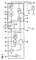
- the embodiment according to Fig. 1 relates to a substantially analog measuring device.
- the high frequency generator 13 includes a harmonic oscillator 22 for generating a high frequency cell.
- the voltage amplitude U c of the generated high-frequency wave is preferably kept constant by means of a control device 23-26 in order to allow a measurement uninfluenced by fluctuations in the input amplitude.
- the high-frequency wave generated by the harmonic oscillator 22 - is fed to a controllable amplifier 23.
- the output signal of the amplifier 23 is fed to a rectifier 24, whose output signal is passed through the low-pass filter 25 to a controller 26.
- the controller 26 controls the amplifier 23 in such a way that the amplitude U c of the harmonic oscillation at the output of the amplifier 23 has a constant value.
- the measuring circuit 27 is the directly connected to dan measuring capacitor 11 part of the circuit device 28. Suitable here is each measuring circuit, which is set up to produce a sufficient Amptituden- and phase change of the high frequency wave as a result of running through the measuring capacitor 11 product 12.
- Two preferred embodiments of the measuring circuit 27 are in the FIGS. 2 and 3 shown, wherein the measuring capacitor 11, a resistor 29 and an inverting operational amplifier 30 in a differentiating arrangement according to Fig. 2 or an integrating arrangement according to Fig. 3 are switched.
- the non-inverting input of the operational amplifier 30 is suitably grounded.
- An additional resistor 31 is provided to prevent, if appropriate, that the output signal is running in the limit.
- the output signal of the measuring circuit 27 corresponding to the outgoing high-frequency wave experiences, due to the interaction with the tobacco 12, a voltage amplitude which is changed with respect to the input amplitude U a U a and a phase shift of ⁇ with respect to the input signal.
- the high-frequency wave passing through the measuring capacitor 11 is conducted via the output line 17 of the measuring circuit 27 to the measured variable determining device 18.
- the measured variable determining device 18 determines suitable measured variables from the high-frequency signal.
- the output of the measuring circuit 27 is supplied to a rectifier 32 and smoothed in a low-pass filter 33.
- the signal thus obtained is proportional to the output amplitude U a .
- the Meß bodinbeticians shark 18 is further supplied to the input signal generated by the high-frequency exciter 13 via the line 34.
- a signal dependent on the generated high-frequency wave is expediently conducted to the circuit device 28 via a line 34, 234 provided in addition to the measuring line via the measuring capacitor 11 in order to be able to use the phase information of the input signal for determining the phase shift of the output signal.
- the input signal of the measuring capacitor 11 via the line 34 and the output of the measuring capacitor 11 and the measuring circuit 27 is passed via a line 35 to the Multiéessverstörker 36, multiplied therein and smoothed by means of a low-pass filter 37.
- the signal thus obtained is proportional to the output amplitude U a times the sine (or cosine) of the phase shift ⁇ .
- any foreign matter 90 contained in the product 12 can be detected when a deviation is detected.
- the measurement signals are conducted via the output lines 19, 20 to the evaluation device 21, in which the evaluation is carried out, for example, by means of a computer program stored therein.
- FIG Fig. 4 A preferred embodiment of a high frequency sensor 38 is shown in FIG Fig. 4 shown.
- the sensor 38 is constructed substantially rotationally symmetrical about the longitudinal axis L. Through a central longitudinal bore 39 of the sensor 38 is in the transport direction T, which coincides with the longitudinal direction L, the Tobacco strand out.
- the sensor comprises two rotationally symmetrical, disc-shaped, oriented perpendicular to the longitudinal direction L main body 40, 41, which are spaced apart by means of an outer, annular, non-conductive limiting body 44 and each have a central through bore 39 for the tobacco rod Nuf und.
- the measuring capacitor 11 is therefore designed as a plate capacitor with plate-shaped electrodes 15, 16, which are oriented in a circular disk and perpendicular to the longitudinal direction L and have a central fürgangsül réelle for the tobacco rod 12.
- the field lines are substantially parallel to the transport direction.
- a field-filled space 45 is formed, which is closed by the limiting body 44 radially outward.
- the high frequency field extends into the central product space 46 and is there with the tobacco 12 in interaction.
- the plates 15, 16 have a smaller radius than the base body 40, 41 in order to prevent leakage of the high-frequency field in the vicinity of the sensor.
- the plates 15, 16 of the plate capacitor 11 may be arranged at a small distance d from each other to improve the measuring resolution in the longitudinal direction L.
- the distance d may in particular be less than the diameter of the tobacco rod 12 and, for example, less than 8 mm, preferably less than 4 mm.
- the base bodies 40, 41 each have a tubular, axially outwardly extending, the tobacco rod comprehensive extension 47, 48.
- the extensions 47, 48 have an inner-walled metallic surface or coating 49, which is expediently connected to the electrodes 15, 16.
- the metallic coating 49 forms a metallic chimney to connect the field leakage from the product feedthrough openings of the capacitor 11. Furthermore, a tobacco pipe 12 immediately surrounding and this leading, extending over the entire length of the sensor extending tube 50 made of non-conductive material, which prevents contamination of the sensor interior by product residues.
- the field-filled space formed between the electrodes 15, 16 45 to the positive influence of the field profile partially or completely, except for the product space to be filled with a dielectric material.
- the bodies 40, 41, 44 of the sensor 38 are preferably made of a non-conductive material having a very low coefficient of thermal expansion, for example Zerodur, in order to achieve increased dimensional stability of the sensor 38 against temperature influences. Due to the reduced dependence of the capacitance characteristics of the measuring capacitor 11 on the ambient temperature, an improved measuring accuracy can be achieved.
- a control device (not shown) is preferably provided for keeping the sensor temperature constant. It is also conceivable that the base body 40, 41 of the sensor 38 completely or partially made of metal.
- FIG Fig. 5 An embodiment of a sensor 38 not covered by the invention is shown in FIG Fig. 5 shown, wherein corresponding parts are denoted by corresponding reference numerals 100.
- the electrodes 15, 16 are formed by plates, which are arranged parallel to the transport direction oriented perpendicular to the paper plane.
- the field lines run in this example substantially perpendicular to the transport direction.
- the plates 15, 16 are preferably arranged around the product strand 12 and preferably curved to this end.
- FIG Fig. 6 A preferred embodiment of a measuring device 10 is shown in FIG Fig. 6 shown, wherein corresponding parts are denoted by corresponding reference numerals 200th
- the measured variable determining device 18 is implemented digitally electronic.
- the Meß Strukturnbeticians Branson Inc.
- the A / D converter 66 is clocked at a sampling frequency which is higher by a factor n than the frequency of the high frequency wave, where n is a natural number greater than one.
- the measuring device 10 has a means 222 for generating a scanning signal having a sampling frequency, the order a factor n is higher than the frequency of the high frequency wave.
- the sampling signal is passed via line 70 to the A / D converter 66.
- the measured values sampled by means of the A / D converter 66 are passed to the digital processing device 67, which is programmed to determine suitable, independent measured quantities.
- each sampled measured value is multiplied on the one hand with the corresponding value of the sine function and on the other hand with the corresponding value of the cosine function.
- the scanning signal is passed via the line 70 to the processing device 67.
- the sine and cosine values can, for example, be taken from corresponding tabular memories 68, 69.
- the n sine values and n cosine values thus obtained are then summed separately over a period of the high frequency field so that two sums are obtained.
- the high-frequency input signal is passed via the line 234 to the processing device 67, so that it operates in phase with the high-frequency generator 13. From the sums obtained, the two desired measured quantities dependent on the amplitude and the phase of the measurement signal influenced by the product 12 can be unambiguously determined on the basis of specific orthogonality relationships.
- the measurement signals are conducted via the output lines 19, 20 to the evaluation device 21, in which the evaluation is carried out, for example, by means of a computer program stored therein.
- the signal generated by the radio frequency source 222 may also be used to generate the radio frequency wave used for the measurement.
- the signal generated by the high-frequency source 222 by the divider stage 60 is divided by a factor n on a phase-synchronous square wave with the measuring frequency of 5 MHz in the present case and then by means of the PLL circuit 61 in a phase-synchronous sinusoidal signal with the same frequency transformed.
- control device 223, 62-64, 226 for keeping constant the voltage amplitude U e of the output from the amplifier 223 high-frequency wave can digitally electronic be executed.
- the output signal of the amplifier 223 is fed to an A / D converter 62 which is driven via a line 65 with the sampling signal of 50 MHz, whereby n samples of the signal output by the amplifier 223 are generated per period.
- the measured values sampled by the A / D converter 62 are sent to the digital processing device 63.
- each sampled voltage value is multiplied by the corresponding value of the cosine function.
- the scanning signal is passed via the line 65 to the processing device 63.
- the cosine values can, for example, be taken from a corresponding tabular memory 64. The n cosine values obtained in this way are then summed over a period of the high-frequency field.
- the high-frequency input signal is passed via a line 71 to the processing device 63, so that it operates in phase with the high-frequency generator 13.
- the output of the processor 63 is passed to the controller 226, which controls the amplifier 223 in such a way that the output signal of the processing means 63 and thus the amplitude U c of the oscillation at the output of the amplifier 223 has a constant value.
- Fig. 7 serves in particular for measurement on a wide, web-shaped product 312, for example a tobacco web, a tow web or a cotton fleece whose width B is substantially greater, for example at least a factor of 3, than its height H.
- a wide, web-shaped product 312 for example a tobacco web, a tow web or a cotton fleece whose width B is substantially greater, for example at least a factor of 3, than its height H.
- Another application relates to the measurement a plurality of juxtaposed product strands, such as tobacco strands.
- the transport direction is perpendicular to the paper plane.
- Corresponding parts are designated by corresponding 300 reference numerals.
- a plurality of measuring capacitors 311A, 311B, ... are used, here for example six, which are arranged across the width of the product.
- the measuring capacitors 311A, 311B, ... are suitably fed by the same high-frequency energizing device 13.
- all of the input electrodes 315 of the measuring capacitors 311A, 311B, ... are set to the same potential, most simply by shorting the electrodes, as in FIG Fig. 7 shown.
- the measuring circuit 80A, 80B, ... are connected to a measuring circuit 80A, 80B, ..., respectively.
- the measuring circuit 80A, 80B,... Is preferably as in FIG Fig. 8 and, together with the respective measuring capacitor 311A, 311B,..., forms a differential measuring circuit 27 as in FIG Fig. 2 shown.
- the use of a respective inverting operational amplifier 330 connected downstream of the measuring capacitor 311A, 311B,... Is particularly advantageous in this embodiment, since in this way the output electrodes 316A, 316B,... Of all measuring capacitors 311A, 311B,. in particular mass be laid. As a result, the crosstalk between the measuring capacitors 311A, 311B, ... is minimized.
- a measured-quantity determination device 18A, 18B,... which is in particular digital-electronic, for example as shown in FIG Fig. 6 shown, can be executed.
- the Meß Strukturnbeticians wornen 18A, 18B, ... are suitably connected to the evaluation device 21 for foreign body detection.
- the corresponding methods for determining the measured variables and for detecting foreign bodies are preferably carried out as described above.
Description
Die Erfindung betrifft eine Meßvorrichtung zur Erkennung von Frerndkörpern in Tabak, nach dem Oberbegriff von Anspruch 1. Die Erfindung betrifft weiterhin ein entsprechendes Meßverfahren.The invention relates to a measuring device for detecting foreign bodies in tobacco, according to the preamble of claim 1. The invention further relates to a corresponding measuring method.
Zur Erkennung von Frerndkörpern in Tabak ist beispeielsweise aus den Dokumenten
Aus dem Dokument
Ferner zeigt die Schrift
Aus dem Dokument
Dokument
Die
Die Aufgabe der vorliegenden Erfindung besteht darin, eine baulich einfache Meßvorrichtung zur Frerndkörperbestimmung mit hoher Meßgenauigkeit bereitzustellen.The object of the present invention is to provide a structurally simple measuring device for Friederkörperbestimmung with high accuracy.
Die Erfindung löst diese Aufgabe mit den Merkmalen der Ansprüche 1 und 20 Durch die Verwendung eines Kondensators, insbesondere anstelle eines Mikrowellenresonators, und eines Hochftequenzfeldes unterhalb des Mikrowellenbereichs kann der schaltungstechnische Aufwand Signifikant reduziert werden. Zudem kann unter Umständen mittels eines Kondensators ein homogeneres Feld in dem Produktraum erzeugt werden als mittels eines Mikrowellenresonators, bei dem die elektrische Feldstärke an der Umfangswand verschwindet.The invention achieves this object with the features of
Der Begriff "Freindkörper" bedeutet jedes andersartige Material, das in dem zu prüfenden Zweistoffsystem unerwüschterweise zusätzlich vorhanden ist. Das zu prüfende Zweistoffsystem wird insbesondere von Tabak und Feuchte (bzw. Soße), oder Filtermaterial und Triacetin. Die Erfindung unterscheidet sich dann von bekannten kapazitiven Meßvorrichtungen im Hochfrequenzbereich zur Erkennung von Masse oder Dichtefehlern beispielsweise in Tabak, die nur das Zweikomponentensystem von Produkt und Feuchte betreffen. Ein Fremdkörper beeinflußt aufgrund seiner abweichenden dielektrischen Eigenschaften in bestimmter Weise das Hochfrequenzfeld und daher die ermittelten Meßgrößen. Durch geeignete Auswertung in der Auswertecinrichtung kann aus den ermittelten Meßgrößen ein Fremdkörper in dem Produkt erkannt werden, insbesondere wenn der Verlauf einer Meßgröße eine von dem Fremdkörper hervorgerufene Abweichung zeigt.The term "free body" means any other type of material that is undesirably present in the binary system to be tested. The dual-substance system to be tested is particularly of tobacco and moisture (or sauce), or filter material and triacetin. The invention then differs from known capacitive measuring devices in High frequency range for detection of mass or density errors, for example in tobacco, which only affect the two-component system of product and moisture. Due to its differing dielectric properties, a foreign body in a certain way influences the high-frequency field and therefore the measured variables determined. By suitable evaluation in the evaluation device, a foreign body in the product can be recognized from the measured variables determined, in particular if the course of a measured variable shows a deviation caused by the foreign body.
Der Begriff "Hochfrequenz" bedeutet grundsätzlich, in Abgrenzung vom Mikrowellenbereich, Felder mit einer Frequenz unterhalb von 100 MHz, vorzugsweise unterhalb von 10 MHz. In der Regel beträgt die Frequenz mehr als 100 kHz. In einer bevorzugten Variante der Erfindung wird ein Hochfrequenzfeld mit einer Frequenz unterhalb von 5 MHz, vorzugsweise unterhalb von 1 MHz verwendet. Dies ist überraschend, da es bezüglich der Messung der Feuchte und/oder Dichte des Produkts bekannt ist, daß zur niedrigeren Frequenzen hin eine hinreichend genaue Messung nur in einem zunehmend einschränkten Meßbereich möglich ist, so daß für Tabak eine Meßfrequenz von mindestens 5 MHz als zweckmäßig gilt. Für die Bestimmung von Freindkörpern Tabak ergibt sich jedoch gerade bei niedrigeren Frequenzen eine größere Meßempfindlichkeit. Eine Erklärung hierfür besteht darin, daß bei niedrigeren Frequenzen die makroskopische Leitung einen zunehmenden Einfluß hat, wobei dies jedoch nicht für typische nicht-leitende Fremdkörper-Materialien (oder allgemeiner solche mit abweichender makroskopischer Leitfähugkeit) zutrifft, so daß der Unterschied in den Dielektrizitätskonstanten zwischen Produkt und Fremdkörper im erfindungsgemäßen Meßbereich größer ist als im Mikrowellenbereich.The term "high frequency" basically means, in contrast to the microwave range, fields with a frequency below 100 MHz, preferably below 10 MHz. As a rule, the frequency is more than 100 kHz. In a preferred variant of the invention, a high-frequency field with a frequency below 5 MHz, preferably below 1 MHz is used. This is surprising, since it is known with respect to the measurement of the moisture and / or density of the product that at lower frequencies a sufficiently accurate measurement is possible only in an increasingly limited range, so that for tobacco a measuring frequency of at least 5 MHz as appropriate applies. For the determination of Freindkörpern tobacco, however, results in a greater sensitivity especially at lower frequencies. One explanation for this is that at lower frequencies the macroscopic conduction has an increasing influence, but this is not true for typical non-conducting foreign body materials (or more generally those with deviating macroscopic conductivity), so that the difference in dielectric constant between product and foreign body in the measuring range according to the invention is greater than in the microwave range.
Infolge der bevorzugten Verwendung einer laufenden Hochfrequenzwelle und einer im wesentlichen nicht-resonanten Schaltungscinrichtung, bei der also der Meßkondensator nicht frequenzbestimmender Teil eines Meß-Schwingkreises ist, kann auf die Verwendung einer gegenüber Temperatureinflüssen empfindlichen Schwingkreis-Spule verzichtet werden. "Im wesentlichen" bedeutet, daß resonante Feldkomponenten nicht ausgeschlossen sind, solange das Meßprinzip im wesentlichen auf einer fortschreitenden Welle beruht. Da keine Resonanzbedingung für einen Meßschwingkreis eingehalten werden muß, kann der Meßkondensator eine gegenüber dem Stand der Technik verringerte Kapazität von vorzugsweise weniger als 10 pF aufweisen, was den Aufwand und die Baugröße reduziert. Die geschilderte bevorzugte Ausführungsform unterscheidet sich daher von bekannten kapazitiven Meßvorrichtungen im Hochfrequenzbereich zur Erkennung von Masse- oder Dichtefehlern in Tabak, bei denen ein Meßkondensator und eine Spule als frequenzbestimmende Teile in einem Hochfrequenz-Schwingkreis geschaltet sind, wobei als Meßgrößen beispielsweise die von dem Produkt beeinflußte Resonanzfrequenz und Resonanzamplitude des Hochfrequenzfeldes bestimmt werden.Due to the preferred use of a current high-frequency wave and a substantially non-resonant Schaltungscinrichtung, in which therefore the measuring capacitor is not frequency-determining part of a measuring resonant circuit, can be dispensed with the use of a temperature sensitive sensitive resonant circuit coil. "Substantially" means that resonant field components are not excluded as long as the measurement principle is essentially based on a traveling wave. Since no resonance condition for a measuring circuit is respected must be, the measuring capacitor may have a relation to the prior art reduced capacity of preferably less than 10 pF, which reduces the effort and size. The described preferred embodiment therefore differs from known capacitive measuring devices in the high frequency range for detecting mass or density errors in tobacco, in which a measuring capacitor and a coil are connected as frequency-determining parts in a high-frequency resonant circuit, wherein as measured variables, for example, those influenced by the product Resonance frequency and resonance amplitude of the high frequency field can be determined.
Vorzugsweise beruht die Fremdkörpererkennung darauf, daß zwei unabhängige Meßgrößen, insbesondere eine von der Kapazität des Meßkondensators abhängige Meßgröße und eine vom Verlustfaktor des Meßkondensators abhängige Meßgröße, in einem von dem erwarteten Verlauf abweichenden Verhältnis stehen. Vorzugsweise ist daher die Messung zweier unabhängiger Meßgrößen vorgesehen. Vorteilhafterweise werden dabei zwei von der Amplitude und der Phase der Hochfrequenzwelle abhängige Meßgrößen bestimmt. Grundsätzlich ist daher die Erzeugung einer Hochfrequenzwelle ausreichend, was den Aufwand gegenüber solchen Vorrichtungen reduziert, die auf der Verwendung mehrerer Hochfrequenzwellen unterschiedlicher Hochfrequenzen beruhen. Die Bestimmung zweier unabhängiger Meßgrößen ist aber nicht zwingend; es ist auch denkbar, eine Fremdkörpererkennung aus dem Verlauf lediglich einer Meßgröße vorzunehmen.The foreign object recognition is preferably based on the fact that two independent measured variables, in particular a measured variable dependent on the capacitance of the measuring capacitor and a measured variable dependent on the loss factor of the measuring capacitor, are in a different relationship to the expected curve. Preferably, therefore, the measurement of two independent measures is provided. Advantageously, two measured variables dependent on the amplitude and the phase of the high-frequency wave are determined. Basically, therefore, the generation of a high frequency wave is sufficient, which reduces the effort compared to such devices, which are based on the use of multiple high frequency waves of different high frequencies. However, the determination of two independent measured quantities is not mandatory; It is also conceivable to carry out a foreign body detection from the course of only one measured variable.
Der zur Bestimmung der Meßgrößen dienende Teil der Schaltungseinrichtung ist in der Regel der eigentlichen Meßschaltung, die den Meßkondensator umfaßt, nachgeschaltet. Während die Meßschaltung in der Regel einen Ausgang für das von dem Produkt beeinflußte Hochfrequenzfeld aufweist, weist die Meßgrößenbestimmungseinrichtung in der Regel eine der Zahl der zu bestimmenden Meßgrößen entsprechende Zahl von Ausgängen, vorzugsweise daher zwei Ausgänge auf. Es ist auch möglich, daß die Meßschaltung und die Meßgrößenbestimmungseinhchtung eine Einheit bilden. Die Meßgrößenbestimmungseinrichtung ist der eigentlichen Auswerteeinrichtung zur Fremdkörpererkennung durch Auswerten des Meßsignals vorgeschaltet. Es ist auch möglich, daß die Meßgrößenbestimmungseinrichtung und die Auswerteeinrichtung eine Einheit bilden. Bei einer bevorzugten Ausführungsform ist der zur Bestimmung der Meßgröße bzw. Meßgrößen dienende Teil der Schaltungseinrichtung digitalelektronisch ausgeführt. Dies ermöglicht die Verwendung einfacher Verfahren zur Bestimmung der gewünschten Meßgröße, beispielsweise des kapazitiven Anteils und/oder des Verlustanteils des Ausgangsspannungswertes der Meßschaltung. Ein besonders einfaches und daher bevorzugtes Verfahren beruht auf der Orthogonalität der Sinus- und Kosinusanteile und umfaßt die Messung einer diskreten Anzahl von n Meßwerten, beispielsweise Spannungswerten, über jede Schwingungsperiode des Hochfrequenzfeldes, separate Multiplikation der n Meßwerte mit entsprechenden Sinus- und Kosinus-Werten und separate Aufsummierung dieser Sinus- und Kosinus-Produkte. Die erhaltenen Summen stellen die Meßgrößen dar oder können zur Ermittlung der Meßgrößen weiterverarbeitet werden.The part of the circuit device serving to determine the measured variables is usually connected downstream of the actual measuring circuit which comprises the measuring capacitor. While the measuring circuit usually has an output for the affected by the product high-frequency field, the Meßgrößenbestimmungseinrichtung usually one of the number of measured variables to be determined corresponding number of outputs, preferably therefore two outputs. It is also possible that the measuring circuit and the Meßgrößenbestimmungseinhchtung form a unit. The measured variable determining device is connected upstream of the actual evaluation device for foreign body recognition by evaluating the measuring signal. It is also possible that the measured variable determining device and the evaluation device form a unit. In a preferred embodiment, the portion of the circuit device serving to determine the measured quantity or measured variables is designed to be digital-electronic. This allows the use of simple methods for determining the desired measured variable, for example the capacitive component and / or the loss component of the output voltage value of the measuring circuit. A particularly simple and therefore preferred method is based on the orthogonality of the sine and cosine components and comprises the measurement of a discrete number of n measured values, for example voltage values, over each oscillation period of the high-frequency field, separate multiplication of the n measured values with corresponding sine and cosine values and separate summation of these sine and cosine products. The sums obtained represent the measured variables or can be further processed to determine the measured variables.
Eine besonders einfache Form einer Meßschaltung, d.h. den Meßkondensator umfassenden Teil der Schaltungseinrichtung, ist ein RC-Glied, vorzugsweise mit einem Operationsverstärker. Dabei handelt es sich vorzugsweise um ein RC-Differenzierglied, es kann aber beispielsweise auch ein RC-Integrierglied verwendet werden.A particularly simple form of measuring circuit, i. The measurement capacitor comprising part of the circuit device is an RC element, preferably with an operational amplifier. This is preferably an RC differentiator, but it can also be used, for example, an RC integrator.
In einer bevorzugten Ausführungsform bestehen Teile des Sensors aus einem Material mit geringem Temperaturausdehnungskoeffizienten, um die Einflüsse von Temperaturschwankungen auf die Meßgenauigkeit möglichst gering zu halten. Zu dem gleichen Zweck kann der Sensor eine zusätzliche Einrichtung zur Konstanthaltung der Temperatur des Meßkondensators aufweisen. Auch eine zusätzliche Einrichtung zur Messung der Temperatur des Meßkondensators, beispielsweise ein Temperaturfühler, ist denkbar, um das Meßsignal entsprechend korrigieren zu können.In a preferred embodiment, parts of the sensor are made of a material with a low coefficient of thermal expansion in order to minimize the effects of temperature fluctuations on the measurement accuracy. For the same purpose, the sensor may have an additional means for keeping constant the temperature of the measuring capacitor. An additional device for measuring the temperature of the measuring capacitor, for example a temperature sensor, is conceivable in order to be able to correct the measuring signal accordingly.
Vorzugsweise ist der Kondensator im wesentlichen senkrecht zu der Transportrichtung des Produkts angeordnet. Bei einem Plattenkondensator sind also die Kondensatorplatten senkrecht zu der Transportrichtung angeordnet. Dies ermöglicht es, die Elektroden in einem kurzen Abstand voneinander, beispielsweise unterhalb der Strangdicke des Produkts, anzuordnen. Hierdurch kann eine verbesserte Auflösung bezüglich der Fremdkörpererkennung in Längsrichtung, und damit eine Steigerung der Nachweisempfindlichkeit, erreicht werden.Preferably, the capacitor is arranged substantially perpendicular to the transport direction of the product. In a plate capacitor so the capacitor plates are arranged perpendicular to the transport direction. This makes it possible to arrange the electrodes at a short distance from each other, for example below the strand thickness of the product. As a result, an improved resolution with respect to the foreign body recognition in the longitudinal direction, and thus an increase in the detection sensitivity, be achieved.
Der Sensor ist zur Durchführung des Produkts durch den zwischen den Elektroden des Meßkondensators gebildete Raum eingerichtet, um eine möglichst vollständige und gleichmäßige Erfassung des Produkts zu ermöglichen.The sensor is designed to pass the product through the space formed between the electrodes of the measuring capacitor in order to allow as complete and uniform detection of the product as possible.
Eine nicht von den Erfindung abgedechte Ausführungsform betrifft die Messung eines relativ breiten Produkts, beispielsweise einer Tabak- oder Tow-Bahn oder einem Baumwollvlies, oder einer Mehrzahl nebeneinander liegender Produktstränge. Dabei umfaßt der Sensor eine Mehrzahl von über die Bereite des Produkts angeordneten Meßkondensatoren. Diese Anordnung gestattet auf einfache Weise eine laterale Positionsbestimmung eines detektierten Fremdkörpers. Die mit der Hochfrequenzfeld-Erzeugungseirichtung verbundenen Elektroden sind auf gleichem Potential gehalten, beispielsweise einfach kurzgeschlossen, um das Übersprechen zwischen den Meßkondensatoren zu minimieren. Zum gleichen Zweck sind vorzugsweise auch die anderen Elektroden jeweils mittels invertierender Operationsverstärker virtuell auf dem gleichem Potential gehalten.An embodiment not covered by the invention relates to the measurement of a relatively wide product, for example a tobacco or tow web or a cotton fleece, or a plurality of adjacent product strands. In this case, the sensor comprises a plurality of measuring capacitors arranged over the width of the product. This arrangement allows in a simple way a lateral position determination of a detected foreign body. The electrodes connected to the radio-frequency field generation device are kept at the same potential, for example simply short-circuited, in order to minimize crosstalk between the measuring capacitors. For the same purpose, the other electrodes are also preferably kept virtually at the same potential by means of inverting operational amplifiers.
Weitere vorteilhafte Merkmale gehen aus den Unteronsprüchen und der folgenden Beschreibung vorteilhafter Ausführungsbeispiele unter Bezugnahme auf die beigefügten Zeichnungen hervor. Es zeigen:
- Fig. 1:
- eine schematische Schaltung einer im wesentlichen analogen Meßvorrichtung;
- Fig. 2:
- eine Differenzier-Meßschaltung für eine Meßvorrichtung;
- Fig. 3:
- eine Integrier-Meßschaltung für eine Meßvorrichtung;
- Fig. 4:
- eine Längssehnitsansicht eines kapazitiven Sensors;
- Fig. 5:
- eine Querschnitsansicht eines kapazitiven Sensors in einer Ausführungsform, die nicht von der vorliegenden Erfindung abgedecht ist;
- Fig. 6:
- eine schematische Schaltung einer im wesentlichen digitalen Meßvorrichtung;
- Fig. 7:
- eine schematische Schaltung eine nicht von der Erfindung abgedeckten Meßvorrichtung für die Messung an einem breiten Produkt; und
- Fig. 8:
- einen Operationsverstärker für eine Differenzier-Meßschaltung für die Meßvorrichtung aus
Fig. 7 .
- Fig. 1:
- a schematic circuit of a substantially analog measuring device;
- Fig. 2:
- a differential measuring circuit for a measuring device;
- 3:
- an integrating measuring circuit for a measuring device;
- 4:
- a Längssehnitsansicht a capacitive sensor;
- Fig. 5:
- a cross-sectional view of a capacitive sensor in an embodiment, which is not covered by the present invention;
- Fig. 6:
- a schematic circuit of a substantially digital measuring device;
- Fig. 7:
- a schematic circuit a not covered by the invention measuring device for the measurement of a broad product; and
- Fig. 8:
- an operational amplifier for a differential measuring circuit for the measuring device
Fig. 7 ,
Die kapazitive Meßvorrichtung 10 gemäß den
In dem Tabak 12 kann ein unerwünschter Fremdkörper 90 auftreten, beispielsweise ein Kunststoff- oder Metallpartikel. Aufgrund abweichender dielektrischer Eigenschaften beeinflußt der Fremdkörper 90 in bestimmter Weise die Amplitude und Phase der Hochfrequenzwelle und hierdurch auch die ermittelten Meßgrößen. Durch geeignete Auswertung in der Auswerteeinrichtung 21 kann aus den ermittelten Meßgrößen ein Fremdkörper 90 in dem Produkt 12 nachgewiesen werden, insbesondere wenn der erlauf einer Meßgröße eine von dem Fremdkörper 90 hervorgerufene Abweichung zeigt. Beispielsweise können von einem Fremdkörper 90 Ausschläge (spikes) in einer Meßkurve hervorgerufen werden; die Auswerteeinrichtung ist dann zweckmäßigerweise zur Erkennung derartiger Ausschläge in der Meßkurve eingerichtet. Bewährt für die Fremdkörpererkennung ist die Auswertung des Verhältnisses zweier voneinander unabhängiger Meßgrößen. Die Auswerteeinrichtung 21 kann gegebenenfalls ein Entfernungsmittel 91, beispielsweise eine Blasdüse, zur Entfernung eines Teils des Tabaks 12, in dem ein Fremdkörper 90 detektiert wird, steuern.In the
Die Ausführungsform gemäß
Die Meßschaltung 27 ist der unmittelbar mit dan Meßkondensator 11 geschaltete Teil der Schaltungseinrichtung 28. Geeignet ist hierbei jede Meßschaltung, die zur Erzeugung einer hinreichenden Amptituden- und Phasenveränderung der Hochfrequenzwelle infolge des durch den Meßkondensator 11 laufenden Produkts 12 eingerichtet ist. Zwei bevorzugte Ausführungsformen der Meßschaltung 27 sind in den
Die durch den Meßkondensator 11 laufende Hochfrequenzwelle wird über die Ausgangsleitung 17 der Meßschaltung 27 an die Meßgrößenbestimmungseinrichtung 18 geleitet. Die Meßgrößenbestimmungseinrichtung 18 bestimmt aus dem Hochfrequenzsignal geeignete Meßgrößen. Hierzu wird in der Ausfühnungsform gemäß
Eine bevorzugte Ausführungsform eines Hochfrequenzsensors 38 ist in
Die Körper 40, 41, 44 des Sensors 38 bestehen vorzugsweise aus einem nichtleitenden Material mit sehr geriugem Temperaturausdehnungskoeffizienten, beispielsweise Zerodur, um eine erhöhte Formstabilität des Sensors 38 gegen Temperatureinflüsse zu erreichen. Aufgrund der verringerten Abhängigkeit der Kapazitätseigenschaften des Meßkondensators 11 von der Umgebungstemperatur kann eine verbesserte Meßgenauigkeit erreicht werden. Zu dem selben Zweck ist vorzugsweise eine nicht gezeigte Regeleinrichtung zur Konstanthaltung der Sensortemperatur vorgeschen. Es ist auch denkbar, daß die Grundkörper 40, 41 des Sensors 38 vollständig oder teilweise aus Metall bestehen.The
Eine nicht von der Erfindung abgedeakte Ausführungstom eines Sensors 38 ist in
Eine bevorzugte Ausführungsform einer Meßvorrichtung 10 ist in
Die mittels des A/D-Wandlers 66 abgetasteten Meßwerte werden an die digitale Verarbeitungseinrichtung 67 geleitet, die zur Ermittlung geeigneter, voneinander unabhängiger Meßgrößen programmiert ist. Bei einem bevorzugten Meßgrößenermittlungsverfahren wird jeder abgetastete Meßwert einerseits mit dem entsprechenden Wert der Sinusfunktion und andererseits mit dem entsprechenden Wert der Kosinusfunktion multipliziert. Zu diesem Zweck wird das Abtastsignal über die Leitung 70 an die Verarbeitungseinrichtung 67 geleitet. Die Sinus- und Kosinuswerte können beispielsweise aus entsprechenden tabellarischen Speichern 68, 69 entnommen werden. Die auf diese Weise erhaltenen n Sinuswerte und n Kosinuswerte werden dann getrennt über eine Periode des Hochfrequenzfeldes aufsummiert, so daß zwei Summen erhalten werden. Zu diesem Zweck wird das Hochfrequenzeingangssignal über die Leitung 234 an die Verarbeitungseinrichtung 67 geleitet, so daß diese phasengleich mit der Hochfrequenzerzeugungseinrichtung 13 arbeitet. Aus den erhaltenen Summen lassen sich aufgrund bestimmter Orthogonalitätsbeziehungen die zwei gewünschten, von der Amplitude und der Phase des von dem Produkt 12 beeinflußten Meßsignals abhängige Meßgrößen eindeutig ermitteln. Zur entsprechenden Auswertung werden die Meßsignale über die Ausgangsleitungen 19, 20 an die Auswerteeinrichtung 21 geleitet, in der die Auswertung beispielsweise mittels eines darin gespeicherten Computerprogramms durchgerührt wird.The measured values sampled by means of the A /
Zweckmäßigerweise kann das von der Hochfrequenzquelle 222 erzeugte Signal ebenfalls zur Erzeugung der für die Messung verwendeten Hochfrequenzwelle verwendet werden. Zu diesem Zweck wird das von der Hochfrequenzquelle 222 erzeugte Signal mittels der Teilerstufe 60 um den Faktor n auf eine phasensynchrone Rechteckschwingung mit der Meßfrequenz von im vorliegenden Fall 5 MHz heruntergeteilt und anschließend mittels der PLL-Schaltung 61 in ein phasensynchrones sinusförmiges Signal mit der gleichen Frequenz umgewandelt.Conveniently, the signal generated by the
Auch die Regeleinrichtung 223, 62-64, 226 zur Konstanthaltung der Spannungsamplitude Ue der von dem Verstärker 223 ausgegebenen Hochfrequenzwelle kann digitalelektronisch ausgeführt sein. In diesem Fall wird das Ausgangssignal des Verstärkers 223 in einen A/D-Wandler 62 gespeist, der über eine Leitung 65 mit dem Abtastsignal von 50 MHz angesteuert wird, wodurch pro Periode n Abtastwerte des von dem Verstärker 223 ausgegebenen Signals erzeugt werden. Die mittels des A/D-Wandlers 62 abgetasteten Meßwerte werden an die digitale Verarbeitungseinrichtung 63 geleitet. Bei einem bevorzugten Verfahren wird jeder abgetastete Spannungswert mit dem entsprechenden Wert der Kosinusfunktion multipliziert. Zu diesem Zweck wird das Abtastsignal über die Leitung 65 an die Verarbeitungseinrichtung 63 geleitet. Die Kosinuswerte können beispielsweise aus einem entsprechenden tabellarischen Speicher 64 entnommen werden. Die auf diese Weise erhaltenen n Kosinuswerte werden dann über eine Periode des Hochfrequenzfeldes aufsummiert. Zu diesem Zweck wird das Hochfrequenzeingangssignal über eine Leitung 71 an die Verarbeitungseinrichtung 63 geleitet, so daß diese phasengleich mit der Hochfrequenzerzeugungseinrichtung 13 arbeitet. Das Ausgangssignal der Verarbeitungseinrichtung 63 wird an den Regler 226 weitergeleitet, der den Verstärker 223 in der Weise steuert, daß das Ausgangssignal der Verarbeitungseinrichtung 63 und damit die Amplitude Uc der Schwingung am Ausgang des Verstärkers 223 einen konstanten Wert aufweist.Also, the
Die von der Erfindung nicht abgedechte Ausführungsform gemäß
Claims (24)
- Measuring apparatus (10) for the detection of foreign bodies (90) in tobacco (12), having a measuring device (11), a device (13) for generating an alternating electromagnetic field in the measuring device (11), which is influenced by the tobacco (12) which is arranged in a measuring volume (46) of the measuring apparatus (10), a circuit device (28) which comprises the measuring device (11) and which is designed to determine at least one suitable measurable variable of the alternating field influenced by the tobacco (12), and an evaluating device (21) which is designed for detection of the foreign body (90) by suitable evaluation of the measurable variable determined with the circuit device (28), wherein the measuring device (11) is a measuring capacitor designed as a plate capacitor with plate-like electrodes (15, 16), and wherein the frequency of the alternating field in the high-frequency range is more than 100 MHz and below 100 MHz,
characterized in that
a sensor (38) encompassing the measuring capacitor (11) is designed to feed the tobacco (12) through the space formed between the plate-like electrodes (15, 16) of the measuring capacitor (11), wherein
the plate-like electrodes (15, 16) of the measuring capacitor (11) are arranged substantially perpendicularly to an axial direction of transport of the tobacco (12) and wherein
the electrodes (15, 16) of the measuring capacitor (11) each have a central tobacco feedthrough opening as well as
on each plate-like electrode (15, 16) is provided a tubular, axially outwardly extending conducting surface (49) formed from the space formed between the plate-like electrodes and which encompasses the tobacco (12), wherein the conducting surface (49) forms a metallic chimney. - Measuring apparatus according to claim 1, characterised in that the sensor (38) includes two rotationally symmetrical, discoidal base bodies (40, 41) which are oriented perpendicularly to the transport direction and which are spaced apart from each other by means of an outer, annular, non-conductive boundary body (44) in such a way that the field-filled space (45) formed between the base bodies (40, 41) is radially closed off from the outside by the boundary body (44).
- Measuring apparatus according to claim 1 or 2, characterised in that the circuit device (28) is substantially non-resonant at the measuring frequency of the alternating field which is used, and measurement is based on the propagation of a travelling high-frequency wave in the measuring capacitor (11).
- Measuring apparatus according to claim 3, characterised in that the circuit device (28) is designed to determine at least one, preferably two measurable variables independent of each other and dependent on the amplitude and/or the phase shift of the high-frequency wave influenced by the tobacco (12).
- Measuring apparatus according to claim 3 or 4, characterised in that the high-frequency field-generating device (13) has a control device (23-26; 223, 62-64, 226) for keeping constant the amplitude of the high-frequency wave generated.
- Measuring apparatus according to any of claims 1 to 5, characterised in that a part (18) of the circuit device (28) which serves to determine the at least one measurable variable is constructed with digital electronics.
- Measuring apparatus according to claim 6, characterised in that the device (18) for determining the measurable variables is designed to sample the measuring signal with a sampling frequency which is higher by a factor of n than the frequency of the high-frequency field.
- Measuring apparatus according to claim 7, characterised in that the device (18) for determining the measurable variables comprises a digital processing device (67) for separately multiplying n sampled measurements by corresponding sine and cosine values, and for separately adding up these sine and cosine products.
- Measuring apparatus according to any of claims 1 to 8, characterised in that a sensor (38) encompassing the measuring capacitor (11) is at least partially made of a material with a low temperature expansion coefficient.
- Measuring apparatus according to any of claims 1 to 9, characterised in that a sensor (38) encompassing the measuring capacitor (11) has a device for keeping the temperature of the measuring capacitor (11) constant.
- Measuring apparatus according to any of claims 1 to 10, characterised in that the electrodes (15, 16) of the measuring capacitor (11) are formed by a metal coating.
- Measuring apparatus according to any of claims 1 to 11, characterised in that a sensor (38) encompassing the measuring capacitor (11) comprises a non-conducting portion (44; 144) for defining the field-filled space (45) of the measuring capacitor (11).
- Measuring apparatus according to any of claims 1 to 12, characterised in that a sensor (38) encompassing the measuring capacitor (11) has a non-conducting tube (50; 150) directly surrounding the tobacco (12).
- Measuring apparatus according to any of claims 1 to 13, characterised in that the field-filled space (45) formed between the electrodes (15, 16) of the measuring capacitor (11) is partially or completely filled with a dielectric material.
- Measuring apparatus according to any of claims 1 to 14, characterised in that the circuit device (28) is designed to determine a measurable variable dependent on the capacitance of the measuring capacitor (11).
- Measuring apparatus according to any of claims 1 to 15, characterised in that the circuit device (28) is designed to determine a measurable variable dependent on the loss factor of the measuring capacitor (11).
- Measuring apparatus according to any of claims 1 to 16, characterised in that the measuring capacitor (11) forms part of an RC network (11, 29), preferably an RC differentiating network.
- Measuring apparatus according to any of claims 1 to 17, characterised in that the circuit device (28) encompasses an operational amplifier (30), preferably an inverting operational amplifier.
- Measuring apparatus according to any of claims 1 to 18, characterised in that the capacitance of the measuring capacitor (11) is less than 10 pF.
- Measuring method for the detection of foreign bodies in tobacco, having a measuring device in which an alternating electromagnetic field is generated, which is influenced by a foreign body contained in the tobacco, wherein at least one suitable measurable variable of the alternating field influenced by the foreign body is determined, and the measurable variable determined is evaluated for detection of the foreign body, wherein a measuring capacitor is used as the measuring device, which is designed as a plate capacitor with plate-like electrodes (15, 16), and wherein an alternating field
with a frequency greater than 100 kHz and below 100 MHz is used,
characterized in that
the sensor (38) encompassing the measuring capacitor (11) is designed to feed the tobacco (12) through the space formed between the plate-like electrodes (15, 16) of the measuring capacitor (11), wherein
the plate-like electrodes (15, 16) of the measuring capacitor (11) are arranged substantially perpendicularly to an axial direction of transport of the tobacco (12) and wherein
the electrodes (15, 16) of the measuring capacitor (11) each have a central tobacco feedthrough opening as well as
on each plate-like electrode (15, 16) is provided a tubular, axially outwardly extending conducting surface (49) formed from the space formed between the plate-like electrodes and which encompasses the tobacco (12), wherein the conducting surface (49) forms a metallic chimney. - Measuring method according to claim 20, characterised in that measurement is carried out in non-resonant fashion by means of a travelling high-frequency wave.
- Measuring method according to claim 21, characterised in that at least one measurable variable dependent on the amplitude and/or the phase shift of the high-frequency wave influenced by the foreign body is determined.
- Measuring method according to claim 21 or 22, characterised in that the measuring signal is sampled with a sampling frequency which is higher by a factor of n than the frequency of the high-frequency wave.
- Measuring method according to claim 23, characterised in that in each case n sampled measurements are multiplied separately by corresponding sine and cosine values, and these sine and cosine products are added up separately.
Priority Applications (1)
| Application Number | Priority Date | Filing Date | Title |
|---|---|---|---|
| PL05821673T PL1836484T3 (en) | 2004-12-22 | 2005-12-17 | Measuring device and method for recognizing foreign bodies in tobacco |
Applications Claiming Priority (2)
| Application Number | Priority Date | Filing Date | Title |
|---|---|---|---|
| DE102004063229A DE102004063229B4 (en) | 2004-12-22 | 2004-12-22 | Measuring device and method for detecting foreign bodies in a product, in particular in tobacco, cotton or another fiber product |
| PCT/EP2005/013830 WO2006069720A2 (en) | 2004-12-22 | 2005-12-17 | Measuring device and method for recognizing foreign bodies in a product, particularly in tobacco, cotton or another fiber product |
Publications (3)
| Publication Number | Publication Date |
|---|---|
| EP1836484A2 EP1836484A2 (en) | 2007-09-26 |
| EP1836484B1 true EP1836484B1 (en) | 2013-02-13 |
| EP1836484B9 EP1836484B9 (en) | 2013-08-14 |
Family
ID=36013320
Family Applications (1)
| Application Number | Title | Priority Date | Filing Date |
|---|---|---|---|
| EP05821673.0A Active EP1836484B9 (en) | 2004-12-22 | 2005-12-17 | Measuring device and method for recognizing foreign bodies in tobacco |
Country Status (7)
| Country | Link |
|---|---|
| US (1) | US7659730B2 (en) |
| EP (1) | EP1836484B9 (en) |
| JP (1) | JP4660558B2 (en) |
| CN (1) | CN101084432B (en) |
| DE (1) | DE102004063229B4 (en) |
| PL (1) | PL1836484T3 (en) |
| WO (1) | WO2006069720A2 (en) |
Cited By (1)
| Publication number | Priority date | Publication date | Assignee | Title |
|---|---|---|---|---|
| EP3811792B1 (en) | 2019-10-21 | 2022-07-06 | International Tobacco Machinery Poland Sp. z o.o. | A feeding apparatus for feeding a tobacco industry segment |
Families Citing this family (13)
| Publication number | Priority date | Publication date | Assignee | Title |
|---|---|---|---|---|
| DE102004063228B4 (en) * | 2004-12-22 | 2007-06-28 | Hauni Maschinenbau Ag | Measuring device and method for determining a dielectric property, in particular the humidity and / or density, of a product |
| CH699752A1 (en) * | 2008-10-16 | 2010-04-30 | Uster Technologies Ag | DEVICE AND METHOD FOR A CAPACITY measure. |
| CH699753A1 (en) * | 2008-10-16 | 2010-04-30 | Uster Technologies Ag | DEVICE AND METHOD FOR A CAPACITY measure. |
| TWI425183B (en) * | 2010-12-03 | 2014-02-01 | Hon Tech Inc | Immediate inspection of electronic components transfer device |
| DE102011006414C5 (en) | 2011-03-30 | 2021-02-18 | Hauni Maschinenbau Gmbh | Method and device for determining weight fractions in a filter material |
| DE102011083052B4 (en) | 2011-09-20 | 2016-03-10 | Hauni Maschinenbau Ag | Capacitive HF strand measuring device and stranding machine |
| DE102012102340A1 (en) * | 2012-03-20 | 2013-09-26 | Hauni Maschinenbau Ag | Measuring arrangement i.e. 2-channel measuring arrangement, for measuring e.g. strands of tobacco processing industry, has measuring modules attached at base plate, and slots pluggable with module carriers according to slot selection |
| DE102012209954A1 (en) * | 2012-06-14 | 2013-12-19 | Hauni Maschinenbau Ag | Method and device for detecting strand inhomogeneities of a material strand of the tobacco processing industry |
| DE102013217485A1 (en) | 2013-09-03 | 2015-03-05 | Hauni Maschinenbau Ag | Arrangement and method for checking rod-shaped articles of the tobacco-processing industry |
| CN104677955B (en) * | 2015-01-28 | 2017-09-29 | 华中科技大学 | A kind of nonmetallic inclusion detection method |
| DE102018108601A1 (en) * | 2018-04-11 | 2019-10-17 | saturn petcare gmbh | Device for detecting foreign bodies in a substrate stream |
| CN110161056B (en) * | 2019-05-09 | 2023-10-03 | 浙江浙能数字科技有限公司 | Device and method for detecting foreign matters on coal conveying belt in coal conveying system |
| DE102021126221A1 (en) | 2021-10-08 | 2023-04-13 | Endress+Hauser Flowtec Ag | Method and system for distinguishing between the presence of a foreign body or a gas bubble in a medium |
Family Cites Families (27)
| Publication number | Priority date | Publication date | Assignee | Title |
|---|---|---|---|---|
| GB717127A (en) * | 1951-07-27 | 1954-10-20 | Unilever Ltd | Improvements in apparatus for measuring dielectric properties of materials |
| FR1315918A (en) * | 1961-12-14 | 1963-01-25 | Commissariat Energie Atomique | Duct fragment passage detector |
| GB1132763A (en) | 1966-03-03 | 1968-11-06 | Rowntree And Company Ltd | Measuring moisture content and other properties of solids and liquids |
| US3786349A (en) * | 1973-05-03 | 1974-01-15 | Northern Electric Co | Electrical reactance and loss measurement apparatus and method |
| US3979581A (en) * | 1974-02-26 | 1976-09-07 | Hauni-Werke Korber & Co., Kg | Method and arrangement for determining the mass of tobacco or the like by capacitance and attenuation measurements in a resonant high frequency oscillator circuit |
| DE2500299A1 (en) | 1974-03-23 | 1975-09-25 | Hauni Werke Koerber & Co Kg | ARRANGEMENT FOR MEASURING THE DIMENSIONS OF A STREAM OF TOBACCO OR ANY OTHER MATERIAL OF THE TOBACCO-PROCESSING INDUSTRY |
| DE2441832A1 (en) | 1974-08-31 | 1976-03-11 | Hauni Werke Koerber & Co Kg | PROCEDURE AND ARRANGEMENT FOR CAPACITIVE TESTING OF TOBACCO DENSITY IN THE ENDS OF ROD-SHAPED ARTICLES OF THE TOBACCO PROCESSING INDUSTRY |
| US4114090A (en) * | 1976-08-17 | 1978-09-12 | Imasco Limited | Electronic moisture meter |
| DE2700972C3 (en) * | 1977-01-12 | 1980-06-12 | Truetzschler Gmbh & Co Kg, 4050 Moenchengladbach | Method and device for monitoring foreign bodies in a textile fiber fleece |
| CH657437A5 (en) * | 1982-05-18 | 1986-08-29 | Burckhardt Ag Maschf | LUBRICANT MONITORING ARRANGEMENT ON A PISTON COMPRESSOR. |
| DE3743216C2 (en) | 1987-12-19 | 1996-12-19 | Hauni Werke Koerber & Co Kg | High frequency resonant circuit |
| DE3825111A1 (en) | 1988-07-23 | 1990-01-25 | Hauni Werke Koerber & Co Kg | METHOD AND CIRCUIT ARRANGEMENT FOR DETERMINING A CHARACTERISTIC SIZE OF A HF OSCILLATOR |
| US4947131A (en) * | 1989-04-21 | 1990-08-07 | Modern Controls, Inc. | Capacitance bar sensor |
| US5208544A (en) * | 1990-09-26 | 1993-05-04 | E. I. Du Pont De Nemours And Company | Noninvasive dielectric sensor and technique for measuring polymer properties |
| DE19651355B4 (en) | 1996-12-10 | 2004-03-18 | Fresenius Medical Care Deutschland Gmbh | Gas bubble detector |
| US5792938A (en) * | 1996-12-13 | 1998-08-11 | Panametrics, Inc. | Humidity sensor with differential thermal detection and method of sensing |
| EP0902277A1 (en) | 1997-08-13 | 1999-03-17 | Hauni Maschinenbau Aktiengesellschaft | Method and apparatus for the determination of at least one property of a product |
| EP0924513B1 (en) * | 1997-12-18 | 2009-11-25 | Uster Technologies AG | Method and device for measuring the proportions of solid materials in a sample |
| US6076480A (en) * | 1999-02-11 | 2000-06-20 | The United States Of America As Represented By The Secretary Of The Navy | Fuel storing water ballast tank internally structured for reducing retention of water and overboard discharge of fuel |
| JP2001320253A (en) * | 2000-05-12 | 2001-11-16 | Nec Miyagi Ltd | Preamplifier circuit |
| JP4811813B2 (en) * | 2000-05-31 | 2011-11-09 | ウステル・テヒノロジーズ・アクチエンゲゼルシヤフト | Method and apparatus for confirming contaminants in filamentary product moved in the longitudinal direction |
| DE10037180C1 (en) * | 2000-07-31 | 2002-01-17 | Reemtsma H F & Ph | Cigarette foreign body detection method for cigarette manufacturing machine uses combined evaluation of tobacco density and tobacco humidity signals |
| DE10100664A1 (en) * | 2001-01-09 | 2002-07-11 | Hauni Maschinenbau Ag | Procedure for testing a production material |
| WO2002093150A1 (en) * | 2001-05-17 | 2002-11-21 | Siemens Vdo Automotive Corporation | Capacitive fuel sensor |
| EP1327876B1 (en) * | 2002-01-11 | 2003-12-17 | TEWS ELEKTRONIK Dipl.-Ing. Manfred Tews | Method and apparatus for detecting foreign bodies in mass streams using a microwave resonator |
| ITBO20020038A1 (en) * | 2002-01-24 | 2003-07-24 | Gd Spa | METHOD FOR DETECTION AND ELIMINATION OF FOREIGN BODIES IN A TOBACCO FLOW |
| DE102004063228B4 (en) * | 2004-12-22 | 2007-06-28 | Hauni Maschinenbau Ag | Measuring device and method for determining a dielectric property, in particular the humidity and / or density, of a product |
-
2004
- 2004-12-22 DE DE102004063229A patent/DE102004063229B4/en not_active Expired - Fee Related
-
2005
- 2005-12-17 WO PCT/EP2005/013830 patent/WO2006069720A2/en active Application Filing
- 2005-12-17 JP JP2007547351A patent/JP4660558B2/en active Active
- 2005-12-17 PL PL05821673T patent/PL1836484T3/en unknown
- 2005-12-17 EP EP05821673.0A patent/EP1836484B9/en active Active
- 2005-12-17 CN CN2005800441412A patent/CN101084432B/en active Active
- 2005-12-17 US US11/793,948 patent/US7659730B2/en active Active
Cited By (1)
| Publication number | Priority date | Publication date | Assignee | Title |
|---|---|---|---|---|
| EP3811792B1 (en) | 2019-10-21 | 2022-07-06 | International Tobacco Machinery Poland Sp. z o.o. | A feeding apparatus for feeding a tobacco industry segment |
Also Published As
| Publication number | Publication date |
|---|---|
| DE102004063229A1 (en) | 2006-07-13 |
| US20080084220A1 (en) | 2008-04-10 |
| CN101084432B (en) | 2012-03-21 |
| WO2006069720A2 (en) | 2006-07-06 |
| US7659730B2 (en) | 2010-02-09 |
| JP2008524613A (en) | 2008-07-10 |
| EP1836484A2 (en) | 2007-09-26 |
| WO2006069720A3 (en) | 2006-08-10 |
| CN101084432A (en) | 2007-12-05 |
| EP1836484B9 (en) | 2013-08-14 |
| JP4660558B2 (en) | 2011-03-30 |
| PL1836484T3 (en) | 2013-07-31 |
| DE102004063229B4 (en) | 2007-06-14 |
Similar Documents
| Publication | Publication Date | Title |
|---|---|---|
| EP1836484B1 (en) | Measuring device and method for recognizing foreign bodies in tobacco | |
| WO2006069721A2 (en) | Measuring device and method for determining a dielectric property, particularly humidity and/or density, of a product | |
| DE19705260B4 (en) | Arrangement for detecting at least one dielectric property of a substance | |
| DE19610844C2 (en) | Method and system for measuring physical parameters of a workpiece | |
| DE19650112C1 (en) | Device and method for measuring a powder mass flow | |
| DE4406046C2 (en) | Device and method for measuring a powder mass flow | |
| EP2121203B1 (en) | Method and device for differentiating objects influencing an electromagnetic alternating field, particularly metal objects | |
| EP0753755A2 (en) | Device for the measurement of the complex dielectric constant of tobacco | |
| WO2005100924A1 (en) | Device sensor arrangement and method for capacitive positional determination of a target object | |
| DE19906442C2 (en) | Method for measuring the distance between a sensor electrode and a workpiece | |
| EP2347250A1 (en) | Device and method for determining a dielectric property of a capacitor arrangement | |
| DE19651355B4 (en) | Gas bubble detector | |
| DE19734978A1 (en) | Material characteristic determination method | |
| EP1219933B1 (en) | Differential eddy current sensor | |
| EP2567263B1 (en) | Detection of a metal or magnetic object | |
| DE19755417A1 (en) | Evaluation circuit for determining complex impedances, device for measuring complex impedances and use of the device | |
| DE3401140C1 (en) | Device for continuous measurement of thickness | |
| EP3824323B1 (en) | Detector for detecting electrically conductive material | |
| DE102017128472A1 (en) | Inductive proximity switch and method of operating an inductive proximity switch | |
| WO2021223987A1 (en) | Magnetically inductive flow measuring device and method for determining a fill level | |
| DE2507398C3 (en) | Circuit arrangement for testing metallic objects | |
| EP0943913A2 (en) | Method and apparatus for determining the composition of fluidisable solid particles | |
| WO2010136152A1 (en) | Measurement arrangement for capturing a volume flow, and measurement method | |
| DE19924592A1 (en) | Measuring method and device for carrying it out |
Legal Events
| Date | Code | Title | Description |
|---|---|---|---|
| PUAI | Public reference made under article 153(3) epc to a published international application that has entered the european phase |
Free format text: ORIGINAL CODE: 0009012 |
|
| 17P | Request for examination filed |
Effective date: 20070720 |
|
| AK | Designated contracting states |
Kind code of ref document: A2 Designated state(s): AT BE BG CH CY CZ DE DK EE ES FI FR GB GR HU IE IS IT LI LT LU LV MC NL PL PT RO SE SI SK TR |
|
| RAP1 | Party data changed (applicant data changed or rights of an application transferred) |
Owner name: HAUNI MASCHINENBAU AG |
|
| 17Q | First examination report despatched |
Effective date: 20080128 |
|
| DAX | Request for extension of the european patent (deleted) | ||
| GRAP | Despatch of communication of intention to grant a patent |
Free format text: ORIGINAL CODE: EPIDOSNIGR1 |
|
| RTI1 | Title (correction) |
Free format text: MEASURING DEVICE AND METHOD FOR RECOGNIZING FOREIGN BODIES IN TOBACCO |
|
| GRAS | Grant fee paid |
Free format text: ORIGINAL CODE: EPIDOSNIGR3 |
|
| GRAA | (expected) grant |
Free format text: ORIGINAL CODE: 0009210 |
|
| AK | Designated contracting states |
Kind code of ref document: B1 Designated state(s): AT BE BG CH CY CZ DE DK EE ES FI FR GB GR HU IE IS IT LI LT LU LV MC NL PL PT RO SE SI SK TR |
|
| REG | Reference to a national code |
Ref country code: GB Ref legal event code: FG4D Free format text: NOT ENGLISH Ref country code: DE Ref legal event code: R081 Ref document number: 502005013469 Country of ref document: DE Owner name: HAUNI MASCHINENBAU GMBH, DE Free format text: FORMER OWNER: HAUNI MASCHINENBAU AG, 21033 HAMBURG, DE |
|
| REG | Reference to a national code |
Ref country code: AT Ref legal event code: REF Ref document number: 596742 Country of ref document: AT Kind code of ref document: T Effective date: 20130215 |
|
| REG | Reference to a national code |
Ref country code: IE Ref legal event code: FG4D Free format text: LANGUAGE OF EP DOCUMENT: GERMAN |
|
| REG | Reference to a national code |
Ref country code: DE Ref legal event code: R096 Ref document number: 502005013469 Country of ref document: DE Effective date: 20130411 |
|
| REG | Reference to a national code |
Ref country code: NL Ref legal event code: T3 |
|
| REG | Reference to a national code |
Ref country code: LT Ref legal event code: MG4D |
|
| PG25 | Lapsed in a contracting state [announced via postgrant information from national office to epo] |
Ref country code: LT Free format text: LAPSE BECAUSE OF FAILURE TO SUBMIT A TRANSLATION OF THE DESCRIPTION OR TO PAY THE FEE WITHIN THE PRESCRIBED TIME-LIMIT Effective date: 20130213 Ref country code: CY Free format text: LAPSE BECAUSE OF FAILURE TO SUBMIT A TRANSLATION OF THE DESCRIPTION OR TO PAY THE FEE WITHIN THE PRESCRIBED TIME-LIMIT Effective date: 20130213 Ref country code: SE Free format text: LAPSE BECAUSE OF FAILURE TO SUBMIT A TRANSLATION OF THE DESCRIPTION OR TO PAY THE FEE WITHIN THE PRESCRIBED TIME-LIMIT Effective date: 20130213 Ref country code: IS Free format text: LAPSE BECAUSE OF FAILURE TO SUBMIT A TRANSLATION OF THE DESCRIPTION OR TO PAY THE FEE WITHIN THE PRESCRIBED TIME-LIMIT Effective date: 20130613 Ref country code: ES Free format text: LAPSE BECAUSE OF FAILURE TO SUBMIT A TRANSLATION OF THE DESCRIPTION OR TO PAY THE FEE WITHIN THE PRESCRIBED TIME-LIMIT Effective date: 20130524 Ref country code: BG Free format text: LAPSE BECAUSE OF FAILURE TO SUBMIT A TRANSLATION OF THE DESCRIPTION OR TO PAY THE FEE WITHIN THE PRESCRIBED TIME-LIMIT Effective date: 20130513 |
|
| REG | Reference to a national code |
Ref country code: PL Ref legal event code: T3 |
|
| PG25 | Lapsed in a contracting state [announced via postgrant information from national office to epo] |
Ref country code: PT Free format text: LAPSE BECAUSE OF FAILURE TO SUBMIT A TRANSLATION OF THE DESCRIPTION OR TO PAY THE FEE WITHIN THE PRESCRIBED TIME-LIMIT Effective date: 20130613 Ref country code: GR Free format text: LAPSE BECAUSE OF FAILURE TO SUBMIT A TRANSLATION OF THE DESCRIPTION OR TO PAY THE FEE WITHIN THE PRESCRIBED TIME-LIMIT Effective date: 20130514 Ref country code: LV Free format text: LAPSE BECAUSE OF FAILURE TO SUBMIT A TRANSLATION OF THE DESCRIPTION OR TO PAY THE FEE WITHIN THE PRESCRIBED TIME-LIMIT Effective date: 20130213 Ref country code: SI Free format text: LAPSE BECAUSE OF FAILURE TO SUBMIT A TRANSLATION OF THE DESCRIPTION OR TO PAY THE FEE WITHIN THE PRESCRIBED TIME-LIMIT Effective date: 20130213 Ref country code: FI Free format text: LAPSE BECAUSE OF FAILURE TO SUBMIT A TRANSLATION OF THE DESCRIPTION OR TO PAY THE FEE WITHIN THE PRESCRIBED TIME-LIMIT Effective date: 20130213 |
|
| PG25 | Lapsed in a contracting state [announced via postgrant information from national office to epo] |
Ref country code: SK Free format text: LAPSE BECAUSE OF FAILURE TO SUBMIT A TRANSLATION OF THE DESCRIPTION OR TO PAY THE FEE WITHIN THE PRESCRIBED TIME-LIMIT Effective date: 20130213 Ref country code: DK Free format text: LAPSE BECAUSE OF FAILURE TO SUBMIT A TRANSLATION OF THE DESCRIPTION OR TO PAY THE FEE WITHIN THE PRESCRIBED TIME-LIMIT Effective date: 20130213 Ref country code: RO Free format text: LAPSE BECAUSE OF FAILURE TO SUBMIT A TRANSLATION OF THE DESCRIPTION OR TO PAY THE FEE WITHIN THE PRESCRIBED TIME-LIMIT Effective date: 20130213 Ref country code: EE Free format text: LAPSE BECAUSE OF FAILURE TO SUBMIT A TRANSLATION OF THE DESCRIPTION OR TO PAY THE FEE WITHIN THE PRESCRIBED TIME-LIMIT Effective date: 20130213 Ref country code: CZ Free format text: LAPSE BECAUSE OF FAILURE TO SUBMIT A TRANSLATION OF THE DESCRIPTION OR TO PAY THE FEE WITHIN THE PRESCRIBED TIME-LIMIT Effective date: 20130213 |
|
| PLBE | No opposition filed within time limit |
Free format text: ORIGINAL CODE: 0009261 |
|
| STAA | Information on the status of an ep patent application or granted ep patent |
Free format text: STATUS: NO OPPOSITION FILED WITHIN TIME LIMIT |
|
| 26N | No opposition filed |
Effective date: 20131114 |
|
| REG | Reference to a national code |
Ref country code: DE Ref legal event code: R097 Ref document number: 502005013469 Country of ref document: DE Effective date: 20131114 |
|
| BERE | Be: lapsed |
Owner name: HAUNI MASCHINENBAU A.G. Effective date: 20131231 |
|
| REG | Reference to a national code |
Ref country code: CH Ref legal event code: PL |
|
| GBPC | Gb: european patent ceased through non-payment of renewal fee |
Effective date: 20131217 |
|
| PG25 | Lapsed in a contracting state [announced via postgrant information from national office to epo] |
Ref country code: LU Free format text: LAPSE BECAUSE OF FAILURE TO SUBMIT A TRANSLATION OF THE DESCRIPTION OR TO PAY THE FEE WITHIN THE PRESCRIBED TIME-LIMIT Effective date: 20131217 Ref country code: MC Free format text: LAPSE BECAUSE OF FAILURE TO SUBMIT A TRANSLATION OF THE DESCRIPTION OR TO PAY THE FEE WITHIN THE PRESCRIBED TIME-LIMIT Effective date: 20130213 |
|
| REG | Reference to a national code |
Ref country code: IE Ref legal event code: MM4A |
|
| REG | Reference to a national code |
Ref country code: FR Ref legal event code: ST Effective date: 20140829 |
|
| PG25 | Lapsed in a contracting state [announced via postgrant information from national office to epo] |
Ref country code: CH Free format text: LAPSE BECAUSE OF NON-PAYMENT OF DUE FEES Effective date: 20131231 Ref country code: LI Free format text: LAPSE BECAUSE OF NON-PAYMENT OF DUE FEES Effective date: 20131231 Ref country code: IE Free format text: LAPSE BECAUSE OF NON-PAYMENT OF DUE FEES Effective date: 20131217 Ref country code: BE Free format text: LAPSE BECAUSE OF NON-PAYMENT OF DUE FEES Effective date: 20131231 |
|
| PG25 | Lapsed in a contracting state [announced via postgrant information from national office to epo] |
Ref country code: GB Free format text: LAPSE BECAUSE OF NON-PAYMENT OF DUE FEES Effective date: 20131217 Ref country code: FR Free format text: LAPSE BECAUSE OF NON-PAYMENT OF DUE FEES Effective date: 20131231 |
|
| REG | Reference to a national code |
Ref country code: AT Ref legal event code: MM01 Ref document number: 596742 Country of ref document: AT Kind code of ref document: T Effective date: 20131217 |
|
| PG25 | Lapsed in a contracting state [announced via postgrant information from national office to epo] |
Ref country code: AT Free format text: LAPSE BECAUSE OF NON-PAYMENT OF DUE FEES Effective date: 20131217 |
|
| PG25 | Lapsed in a contracting state [announced via postgrant information from national office to epo] |
Ref country code: TR Free format text: LAPSE BECAUSE OF FAILURE TO SUBMIT A TRANSLATION OF THE DESCRIPTION OR TO PAY THE FEE WITHIN THE PRESCRIBED TIME-LIMIT Effective date: 20130213 |
|
| PG25 | Lapsed in a contracting state [announced via postgrant information from national office to epo] |
Ref country code: HU Free format text: LAPSE BECAUSE OF FAILURE TO SUBMIT A TRANSLATION OF THE DESCRIPTION OR TO PAY THE FEE WITHIN THE PRESCRIBED TIME-LIMIT; INVALID AB INITIO Effective date: 20051217 |
|
| REG | Reference to a national code |
Ref country code: DE Ref legal event code: R081 Ref document number: 502005013469 Country of ref document: DE Owner name: HAUNI MASCHINENBAU GMBH, DE Free format text: FORMER OWNER: HAUNI MASCHINENBAU AG, 21033 HAMBURG, DE |
|
| REG | Reference to a national code |
Ref country code: NL Ref legal event code: PD Owner name: HAUNI MASCHINENBAU GMBH; DE Free format text: DETAILS ASSIGNMENT: VERANDERING VAN EIGENAAR(S), VERANDERING VAN DE JURIDISCHE ENTITEIT; FORMER OWNER NAME: HAUNI MASCHINENBAU AG Effective date: 20160928 |
|
| REG | Reference to a national code |
Ref country code: DE Ref legal event code: R081 Ref document number: 502005013469 Country of ref document: DE Owner name: KOERBER TECHNOLOGIES GMBH, DE Free format text: FORMER OWNER: HAUNI MASCHINENBAU GMBH, 21033 HAMBURG, DE |
|
| REG | Reference to a national code |
Ref country code: NL Ref legal event code: HC Owner name: KOERBER TECHNOLOGIES GMBH; DE Free format text: DETAILS ASSIGNMENT: CHANGE OF OWNER(S), CHANGE OF OWNER(S) NAME; FORMER OWNER NAME: HAUNI MASCHINENBAU GMBH Effective date: 20221020 |
|
| PGFP | Annual fee paid to national office [announced via postgrant information from national office to epo] |
Ref country code: PL Payment date: 20221129 Year of fee payment: 18 |
|
| PGFP | Annual fee paid to national office [announced via postgrant information from national office to epo] |
Ref country code: DE Payment date: 20221229 Year of fee payment: 18 |
|
| P01 | Opt-out of the competence of the unified patent court (upc) registered |
Effective date: 20230608 |
|
| PGFP | Annual fee paid to national office [announced via postgrant information from national office to epo] |
Ref country code: NL Payment date: 20231220 Year of fee payment: 19 Ref country code: IT Payment date: 20231227 Year of fee payment: 19 |
|
| PGFP | Annual fee paid to national office [announced via postgrant information from national office to epo] |
Ref country code: PL Payment date: 20231128 Year of fee payment: 19 |