EP1836421B1 - Device for operating selector forks - Google Patents
Device for operating selector forks Download PDFInfo
- Publication number
- EP1836421B1 EP1836421B1 EP06700083A EP06700083A EP1836421B1 EP 1836421 B1 EP1836421 B1 EP 1836421B1 EP 06700083 A EP06700083 A EP 06700083A EP 06700083 A EP06700083 A EP 06700083A EP 1836421 B1 EP1836421 B1 EP 1836421B1
- Authority
- EP
- European Patent Office
- Prior art keywords
- shift fork
- blocking
- gearshift fork
- axial direction
- activation device
- Prior art date
- Legal status (The legal status is an assumption and is not a legal conclusion. Google has not performed a legal analysis and makes no representation as to the accuracy of the status listed.)
- Not-in-force
Links
Images


Classifications
-
- F—MECHANICAL ENGINEERING; LIGHTING; HEATING; WEAPONS; BLASTING
- F16—ENGINEERING ELEMENTS AND UNITS; GENERAL MEASURES FOR PRODUCING AND MAINTAINING EFFECTIVE FUNCTIONING OF MACHINES OR INSTALLATIONS; THERMAL INSULATION IN GENERAL
- F16H—GEARING
- F16H63/00—Control outputs from the control unit to change-speed- or reversing-gearings for conveying rotary motion or to other devices than the final output mechanism
- F16H63/02—Final output mechanisms therefor; Actuating means for the final output mechanisms
- F16H63/30—Constructional features of the final output mechanisms
- F16H63/34—Locking or disabling mechanisms
- F16H63/3408—Locking or disabling mechanisms the locking mechanism being moved by the final actuating mechanism
-
- F—MECHANICAL ENGINEERING; LIGHTING; HEATING; WEAPONS; BLASTING
- F16—ENGINEERING ELEMENTS AND UNITS; GENERAL MEASURES FOR PRODUCING AND MAINTAINING EFFECTIVE FUNCTIONING OF MACHINES OR INSTALLATIONS; THERMAL INSULATION IN GENERAL
- F16H—GEARING
- F16H61/00—Control functions within control units of change-speed- or reversing-gearings for conveying rotary motion ; Control of exclusively fluid gearing, friction gearing, gearings with endless flexible members or other particular types of gearing
- F16H61/26—Generation or transmission of movements for final actuating mechanisms
- F16H61/28—Generation or transmission of movements for final actuating mechanisms with at least one movement of the final actuating mechanism being caused by a non-mechanical force, e.g. power-assisted
- F16H61/30—Hydraulic or pneumatic motors or related fluid control means therefor
-
- F—MECHANICAL ENGINEERING; LIGHTING; HEATING; WEAPONS; BLASTING
- F16—ENGINEERING ELEMENTS AND UNITS; GENERAL MEASURES FOR PRODUCING AND MAINTAINING EFFECTIVE FUNCTIONING OF MACHINES OR INSTALLATIONS; THERMAL INSULATION IN GENERAL
- F16H—GEARING
- F16H63/00—Control outputs from the control unit to change-speed- or reversing-gearings for conveying rotary motion or to other devices than the final output mechanism
- F16H63/02—Final output mechanisms therefor; Actuating means for the final output mechanisms
- F16H63/30—Constructional features of the final output mechanisms
- F16H63/3009—Constructional features of the final output mechanisms the final output mechanisms having elements remote from the gearbox
-
- Y—GENERAL TAGGING OF NEW TECHNOLOGICAL DEVELOPMENTS; GENERAL TAGGING OF CROSS-SECTIONAL TECHNOLOGIES SPANNING OVER SEVERAL SECTIONS OF THE IPC; TECHNICAL SUBJECTS COVERED BY FORMER USPC CROSS-REFERENCE ART COLLECTIONS [XRACs] AND DIGESTS
- Y10—TECHNICAL SUBJECTS COVERED BY FORMER USPC
- Y10T—TECHNICAL SUBJECTS COVERED BY FORMER US CLASSIFICATION
- Y10T74/00—Machine element or mechanism
- Y10T74/20—Control lever and linkage systems
- Y10T74/20012—Multiple controlled elements
- Y10T74/20018—Transmission control
- Y10T74/20024—Fluid actuator
-
- Y—GENERAL TAGGING OF NEW TECHNOLOGICAL DEVELOPMENTS; GENERAL TAGGING OF CROSS-SECTIONAL TECHNOLOGIES SPANNING OVER SEVERAL SECTIONS OF THE IPC; TECHNICAL SUBJECTS COVERED BY FORMER USPC CROSS-REFERENCE ART COLLECTIONS [XRACs] AND DIGESTS
- Y10—TECHNICAL SUBJECTS COVERED BY FORMER USPC
- Y10T—TECHNICAL SUBJECTS COVERED BY FORMER US CLASSIFICATION
- Y10T74/00—Machine element or mechanism
- Y10T74/20—Control lever and linkage systems
- Y10T74/20012—Multiple controlled elements
- Y10T74/20018—Transmission control
- Y10T74/20085—Restriction of shift, gear selection, or gear engagement
- Y10T74/20104—Shift element interlock
- Y10T74/2011—Shift element interlock with detent, recess, notch, or groove
Definitions
- the present invention relates to a shift fork actuation device for selectively actuating at least two shift forks of a transmission, with blocking means for blocking a non-actuable shift fork and with entrainment means for carrying a shift fork to be actuated in an axial direction.
- Such devices are usually part of a speed-torque converter, in particular a two-stage gear change transmission for motor vehicles.
- a gear or ratio change of such used as the main transmission change gear is controlled by two mechanical input signals.
- An input signal is generated by the direction of selection of the gear lever. It has to be decided which of the available gearshift forks should be operated.
- the second input signal is generated by the switching direction of the gear lever. For example, the shift fork can be moved along the shift direction between two shift positions and a neutral position.
- the switching and the direction of selection are transmitted as mechanical signals via a cable or a linkage to the transmission.
- These two mechanical input signals are used at the input of the transmission for the selection of the shift fork to be operated and for the movement of the selected shift fork by the entrainment means between the respective positions.
- These two mechanical input signals are transmitted, for example, in a three-speed main gearbox with reverse gear on two shift forks, which can each take two switching positions and a neutral position.
- it When selecting and subsequently operating the shift fork, it must be ensured that the shift forks only move according to a predetermined shift pattern and that no unauthorized conditions can be set. For example, two shift forks should not be engaged simultaneously.
- the selection movement of the shift lever on the transmission is converted, for example, into a linear movement of a shift finger to select a shift ruler.
- the shift finger slides on a linkage in a movement transverse to the longitudinal axis of the shift ruler in a shift gate, which is formed by recesses in the parallel aligned shift rulers.
- the switching movement ie the operation of a shift fork bearing a shift ruler can be implemented, for example, in a rotational movement of the shift finger, which then via the selected shift ruler, the shift fork along the longitudinal axis of the shift ruler moves and thus parts of the transmission in the power flow on or off.
- the mechanical input signals (the switching and selection direction) can also be assisted or implemented by means of electromotive, pneumatic or hydraulic actuating means and thus the transmission can be controlled.
- US 4,583,418 shows a generic shift fork actuator with a bearing axis, which supports a driver part and a blocking part.
- the invention is therefore the object of a shift fork actuator for a transmission so white develop that the above-mentioned disadvantages are avoided.
- a shift fork actuating device should have a simple structure with very few components.
- the shift fork actuating device builds on the generic state of the art in that it has a bearing axis arranged in the axial direction, which supports at least one blocking part of the blocking means and at least one driver part of the driving means.
- a blocking part and a driver part By the storage of a blocking part and a driver part in a direction extending in the axial direction of the bearing axis is achieved on the one hand, the assembly of the shift fork actuating device with respect to their selection, switching and blocking functions can be performed substantially independently of the remaining components of the transmission.
- the functionality of the shift fork actuating device can also be checked independently of the transmission. Together, this results in a significant advance in terms of safety and productivity-optimized production of manual transmissions.
- the blocking part and the driver part can be by the arrangement of the blocking part and the driver part on the axially disposed bearing axis a significant reduction in components with a constant functionality and thus realize a reduced default probability.
- a short distance between the blocking and entrainment means such as shift rails and cooperating parts of the transmission such as gears can be realized. This allows a short design of the corresponding shift forks.
- this arrangement makes it possible to facilitate the actuation of the bearing part supporting the blocking part and the driver part in an advantageous manner by a power amplification unit or to automate it in whole or in part by means of suitable actuators.
- the bearing axis is formed by a piston rod, in particular by a piston rod of a servo cylinder.
- the power transmission unit in particular the servo cylinder, directly actuate the bearing axis designed as a piston rod and thus support a disengagement or engagement of transmission parts in the power flow and in particular also make automatically.
- the assembly and the test can also be made here independent of the actual transmission.
- the driver part is arranged to be displaceable in the axial direction.
- the driver part can thereby take the shift fork to be actuated in the axial direction along the bearing axis and thus switch parts of the transmission.
- the bearing axis such stores that it can make a rotational movement about the axial direction. In this way, for example, be selected by the rotational movement of the driver part selecting a to-use shift fork.
- a preferred embodiment of the invention provides that the driver part has an outer peripheral portion with a first control contour, which is intended to cooperate with circumferential contours of at least two of the at least two shift forks bearing shift fork rods.
- a first control contour By a corresponding configuration of the first control contour and the circumferential contours of the shift fork rods with which the first control contour of the driver part cooperates, so can be achieved an entrainment of a shift fork to be actuated in an axial direction.
- By appropriate change of position of the driver part to be operated shift forks can be selected and taken, while other non-operated shift forks can be released.
- the first control contour entrains the shift fork to be actuated in the axial direction and at the same time does not act on the shift fork which is not operable.
- the first control contour interacts with the peripheral contour of the shift fork to be actuated when the position of the driver part changes and at the same time does not interact with the peripheral contour of the second non-actuable shift fork. In this way, the shift fork to be operated is selected and can be moved in the axial direction.
- the blocking part is locked with respect to the axial direction. This causes an interaction the blocking means with a non-actuated shift fork blocking the non-actuated shift fork in the axial direction and thus prevents in a simple manner undesirable engagement or disengagement of transmission parts.
- the bearing axle supports the blocking part such that it can execute a rotational movement about the axial direction.
- the blocking part can interact with the shift fork to be actuated and thus block a displacement of the shift fork to be actuated in the axial direction.
- an advantageous embodiment can provide that the blocking part has an outer peripheral portion with a second control contour, which is intended to cooperate with circumferential contours of at least two of the at least two shift forks bearing shift fork rods.
- the blocking part can interact via the second control contour with the peripheral contour of a shift fork rod, which carries a shift fork, which should not be actuated.
- the second control contour blocks a movement of the non-actuated shift fork in the axial direction and at the same time releases a movement of the shift fork to be actuated in the axial direction.
- a further advantageous embodiment results from the fact that a rotational movement of the blocking part is coupled about the axial direction with a rotational movement of the driver part about the axial direction.
- the coupling in particular the synchronization of the rotational movements of the blocking part and the driver part about the axial direction thus causes a suitable rotational movement releasing the shift fork to be actuated, blocking the non-actuated shift fork and at the same time interacting the driver with the shift fork to be actuated in that, in the event of a subsequent axial movement of the driver part, the shift fork to be actuated is driven along in the axial direction, while at the same time the non-actuated shift fork is blocked in the axial direction by the blocking part of the blocking means.
- This coupling of the movements reduces the effort to control the transmission.
- the driver part and the blocking part are arranged coaxially.
- a coaxial arrangement of the driver part and the blocking part on the bearing axis extending in the axial direction allows, for example, a synchronous movement of the driver part and of the blocking part and also allows a relative movement of driver part and blocking part in the axial direction. This allows a simple and cost-effective simultaneous control of driver part and blocking part.
- the driver part has at least one groove.
- One or more of such grooves may cooperate with corresponding pins or lands in, for example, a portion of a housing. This allows a control of the Mitschschulen. For example, an actuation of a shift fork is ensured only within a predetermined shift pattern.
- the invention further relates to a transmission, in particular for motor vehicles, with a shift fork actuating device according to the invention.
- the shift fork actuating device according to the invention can be designed for a manual transmission with cable actuation.
- the invention is based on the finding that a modular transmission control unit is provided by the joint mounting of the blocking and driver part on an axially arranged bearing axis, which can be pre-assembled and tested together with the shift forks. The finished unit can then be installed in the transmission housing. Furthermore, can be realized in this way a simple structure with very few components, the has a small space and are mechanically blocked in the unused forks. Moreover, the entire shift and select mechanism is mountable on a power boost unit, such as a servo cylinder.
- the shift fork actuator shown here is intended for a three-speed main transmission with reverse gear.
- Figures 1a and 1b show a perspective view of the preferred embodiment of a shift fork actuating device according to the invention as well as details of the preferred embodiment of the shift fork actuating device according to the invention.
- the shift fork actuating device 10 according to the invention has three axes arranged in parallel. Two axes are formed by a first shift fork rod 12 and a second shift fork rod 14.
- a bearing rod forms the third axis in the form of a bearing axis 16.
- the shift fork rods 12, 14 are not in shown parts of a gear housing rotatable about its axis and slidably mounted along its longitudinal axis, the bearing axis 16 is slidable along its longitudinal axis.
- the first shift fork rod 12 carries a first shift fork 18, which extends away from the longitudinal axis of the bearing axis 16. Parallel to the plane formed by the first shift fork 18 and also pointing away from the longitudinal axis of the bearing axis 16, a second shift fork 20, which is attached to a free end of the second shift fork rod 14 extends.
- the shift forks 18, 20 essentially each have the shape of a semicircle and each have a guide element 22 on the insides of their ends. These engage in non-illustrated double shift sleeves of the transmission.
- On the bearing axis 16 are the driver part 24 and the blocking part 26.
- the driver part 24 is concentric with the bearing axis 16 and has a guide portion 28, the surface of which is a parallel to the bearing axis aligned polygon cylinder. This polygonal outer surface of the guide portion 28 contacts the likewise aligned polygonal cylindrical inner surface 30 of the blocking member 26, which is also arranged concentrically on the bearing axis 16.
- the driver member 24 and the blocking member 26 can thus move axially relative to each other, but not rotate against each other.
- the blocking part 26 can therefore only perform a rotational movement about the bearing axis 16 together with the driver part.
- a sliding spring can also be selected.
- the driver part 24 further has a first control contour in the form of a driver control contour 32 and the blocking part 26 has a second control contour in the form of a Blocking control contour 34 on.
- the Mitauer practisekontur 32 and the blocking control contour 34 cooperate with corresponding circumferential grooves of the control fork rods 12, 14 together.
- two rotary levers 40, 42 are shown, which can be rotated about the axis 44 and 46, respectively.
- the axles 44, 46 are arranged perpendicular to the axes formed by the shift fork rods 12, 14 and to the longitudinal axis of the bearing axis 16.
- the selector lever 40 is rotatably connected to a selector lever rod 48, which in turn is mounted rotatably about the axis 44.
- the selector lever rod 48 in turn has a rotationally fixed with its associated actuating lever 50 which is perpendicular to the axis 44 and senkecht to the selector lever 40 is arranged.
- This actuating lever actuates a selector rod 52 which extends perpendicular to the axes of the shift fork rods 12, 14 and to the longitudinal axis of the bearing axis 16 and perpendicular to the axis 44 and 46 and in the plane formed by the shift forks 18, 20 level.
- the actuating lever 50 is articulated on the actuating head 54 of the selector rod 52.
- the selector rod 52 is slidably mounted along its axis. It has on its the bearing axis 16 facing surface a toothing 56 which is in engagement with a toothed portion 58 of the blocking part 26.
- the toothed section 58 is arranged on the upper side of the blocking part 26 facing away from the shift forks.
- the shift lever 42 has a rotatable about the axis 46 Shift lever rod 60 and is rotatably connected thereto at one end of the shift lever rod 60.
- the other end of the shift lever rod 60 is rotatably connected to an actuating lever 62. This extends perpendicular to the axis 46 and parallel to the shift lever 42 and contacts the guide portion 28 of the driver 24th
- the rotational movement of the lever 40, 42 must be transformed into a linear movement of the shift forks 18, 20.
- the selector lever 40 and the shift lever 42 first translate the mechanical input signals, that is to say the selection direction and the switching direction, into a rotational movement.
- the mechanical input signals are usually transmitted via a linkage or via a cable (both not shown here) to the transmission. If a selection signal is transmitted to the selector lever 40 via such an arrangement, it thereby turns the selector lever rod 48 about the axis 44 by a certain angle. This rotation is transmitted to the actuating lever 50 on the actuating head 54 of the selector rod 52.
- the blocking part 26 also has a guide nose 64, which is guided in a not shown in this figure groove of the transmission housing. This groove extends parallel to the plane formed by the shift forks and perpendicular to the axis defined by the bearing axis 16.
- the driver part 24 moves relative to the blocking part 26, which prevents axial movement along the longitudinal axis of the bearing axis 16 by the guidance nose 64 guided in a housing groove, not shown here is.
- the selected shift fork rod (12 or 14) makes a shift along its longitudinal axis and in turn takes along the corresponding shift fork (18 or 20) in its movement.
- the corresponding shift sleeve of the transmission is set, ie engaged or disengaged.
- a force boost for example by a servo cylinder, is advantageous for the switching movement.
- its piston rod can form the bearing axis 16.
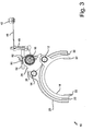
- FIG. 2 shows a plan view of the preferred embodiment of the shift fork actuator according to the invention.
- the second shift fork rod 14 also has a cam peripheral groove 70 and a lock circumferential groove 72.
- the bearing shaft 16 constitutes a piston rod of a servo cylinder.
- the blocking control contour 34 of the blocking part 26 releases, for example, the shift rod 14 on the circumferential groove 72.
- the driver part 24 engages with its driver control contour in the Mitauer Struktursnut 70 of the second shift fork rod 14. If a switching movement is now initiated on the shift lever 42, is over mediates the actuating lever 60, the driver member 24 moves along the axis defined by the bearing axis 16. In this case, the driver part 24 takes the shared by the blocking part 26 and in driving engagement with the driver part 24 located shift fork rod 14 with. In this movement, the movement of the driver part 24 can be supported by a servo cylinder.
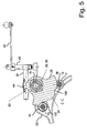
- FIG. 3 shows a front view of the shift fork actuator according to the invention.
- the partially hidden driver part 24 can be seen in front of the blocking part 26.
- the driver part 24 has a notch portion 80 on its side facing away from the shift forks 18, 20.
- a part of the transmission housing is shown, which has a guide groove 82 for the guide lug 64 of the blocking part 26.
- This guide groove 82 may be provided in the housing (for example, milled) or fixed as an additional component on the housing.
- FIG. 4 shows a sectional view taken along the line BB of FIG. 2 ,
- This sectional view illustrates the functionality of the driver part and in particular its driver control contour 32 in cooperation with the circumferential grooves 36, 70 of the shift fork rods 12, 14.
- the circumferential grooves FIGS. 36 and 70 are shown in the sectional view as smaller radii of the shift fork rods 12, 14.
- the driver control contour 32 of the driver part 24 has a first release portion 90 in the vicinity of the first shift fork rod 12 and a second release portion 92 in the vicinity of the second shift fork rod 14.
- the driver part 24 is about its driver control contour 32 in engagement with the circumferential groove 70 of the shift fork rod 14.
- the first shift fork rod 12 free. This has the consequence that with an axial movement of the driver part 24, ie perpendicular to the image plane, the second shift fork rod 14 and with it the second shift fork 20 follow this movement along the longitudinal axis of the shift fork rod 14. The first shift fork rod 12 and the first shift fork 18 connected thereto are not moved during this movement.
- FIG. 5 shows a sectional view taken along the line CC of FIG. 2 ,
- the blocking part 26 has on its blocking peripheral contour 34 a first release section 100 arranged in the vicinity of the first shift fork rod 12 and a second release section 102 arranged in the vicinity of the second shift fork rod 14.
- the blocking part 26 is located with its control peripheral contour 34 in engagement with the circumferential groove 38 of the first shift fork rod 12.
- the second release portion 102 releases the second shift fork rod 12.
- the blocking member 26 blocks the first shift fork rod 12 and allows axial displacement of the second shift fork rod 14.
- the first release portion 100 of the lock control contour 34 releases the first shift fork rod 12 in a predetermined angular position.
- the release of the second Shift fork rod 14 is released by the second release portion 102 and the blocking control contour 34 engages with the blocking circumferential groove 72 of the second shift fork rod 14. In this way, an axial movement of the first shift fork rod 12 is allowed while preventing such movement of the second shift fork rod 14.
- FIG. 6 shows a sectional view taken along the line AA of FIG. 3 ,
- the driver part 24 which extends with a polygonal cylindrical guide portion 28 through the blocking member 26 along the polygonal cylindrical inner surface 30.
- the guide lug 64 of the blocking member 26 is located in the groove 82 located in the housing.
- the selector rod 52 is with its teeth 56 in engagement with the corresponding toothed portion 58 of the blocking member 26.
- the gear housing has a lower web or pin 110 and a flatter web or Pin 112 on. The webs 110, 112 can be machined into the housing or pressed in as pins.
- the shift rod actuator 10 may be desirable in the operation of the shift rod actuator 10 to shift the shift forks 18, 20 only in corresponding shift positions.
- certain axial movements of the driver part 24 may be executable only at certain angular positions or certain other axial movements to be made possible at other specific angular positions.
- a deeper web 110 and a flatter web 112 are mounted in the housing of the transmission.
- the web geometries correspond to the geometries of the notches of the Notch portion 80 of the driver 24.
- the webs and the notches or grooves are positioned against each other so that they can be coupled only at a corresponding rotation of the driver 24. In certain switching schemes, it is also necessary to block the circuit in certain directions.
- the lower web 110 prevents axial displacement of the driver part 24 in the direction of the lower web at certain angular positions of the driver 24, when the notch of the notch portion 80, which engage around the lower web 110 at this angular position would not have the necessary depth. In this way, a targeted restriction of the freedom of movement of the driver part 24 can be achieved by a simple structural measure.
Abstract
Description
Die vorliegende Erfindung betrifft eine Schaltgabelbetäti-Die vorliegende Erfindung betrifft eine Schaltgabelbetätigungsvorrichtung zur wahlweisen Betätigung von zumindest zwei Schaltgabeln eines Getriebes, mit Blockiermitteln zum Blockieren einer nicht zu betätigenden Schaltgabel und mit Mitnehmermitteln zum Mitnehmen einer zu betätigenden Schaltgabel in einer axialen Richtung.The present invention relates to a shift fork actuation device for selectively actuating at least two shift forks of a transmission, with blocking means for blocking a non-actuable shift fork and with entrainment means for carrying a shift fork to be actuated in an axial direction.
Derartige Vorrichtungen sind üblicherweise Bestandteil eines Drehzahl-Drehmomentwandlers, insbesondere eines zweistufigen Zahnrad-Wechselgetriebes für Kraftfahrzeuge. Ein Gang- beziehungsweise Übersetzungswechsel eines derartigen als Hauptgetriebe eingesetzten Wechselgetriebes wird durch zwei mechanische Eingangssignale angesteuert. Ein Eingangssignal wird durch die Wählrichtung des Ganghebels erzeugt. Hierbei ist zu entscheiden, welche der zur Auswahl stehenden Schaltgabeln betätigt werden soll. Das zweite Eingangssignal wird durch die Schaltrichtung des Ganghebels erzeugt. Beispielsweise kann die Schaltgabel entlang der Schaltrichtung zwischen zwei Schaltstellungen und einer Neutralstellung bewegt werden. Üblicherweise werden die Schalt- und die Wählrichtung als mechanische Signale über einen Seilzug oder ein Gestänge zum Getriebe übertragen. Diese beiden mechanischen Eingangssignale werden am Eingang des Getriebes für die Auswahl der zu betätigenden Schaltgabel und für die Bewegung der ausgewählten Schaltgabel durch die Mitnehmermittel zwischen den entsprechenden Positionen verwendet. Diese beiden mechanischen Eingangssignale werden beispielsweise bei einem Drei-Gang-Hauptgetriebe mit Rückwärtsgang auf zwei Schaltgabeln übertragen, die jeweils zwei Schaltstellungen und eine Neutralstellung einnehmen können. Bei der Auswahl und dem nachfolgenden Betätigen der Schaltgabel muss sichergestellt werden, dass sich die Schaltgabeln nur nach einem vorgegebenen Schaltschema bewegen und sich keine unerlaubten Zustände einstellen lassen. Beispielsweise dürfen sich zwei Schaltgabeln nicht gleichzeitig in Eingriff befinden.Such devices are usually part of a speed-torque converter, in particular a two-stage gear change transmission for motor vehicles. A gear or ratio change of such used as the main transmission change gear is controlled by two mechanical input signals. An input signal is generated by the direction of selection of the gear lever. It has to be decided which of the available gearshift forks should be operated. The second input signal is generated by the switching direction of the gear lever. For example, the shift fork can be moved along the shift direction between two shift positions and a neutral position. Usually, the switching and the direction of selection are transmitted as mechanical signals via a cable or a linkage to the transmission. These two mechanical input signals are used at the input of the transmission for the selection of the shift fork to be operated and for the movement of the selected shift fork by the entrainment means between the respective positions. These two mechanical input signals are transmitted, for example, in a three-speed main gearbox with reverse gear on two shift forks, which can each take two switching positions and a neutral position. When selecting and subsequently operating the shift fork, it must be ensured that the shift forks only move according to a predetermined shift pattern and that no unauthorized conditions can be set. For example, two shift forks should not be engaged simultaneously.
Gemäß dem Stand der Technik wird die Wählbewegung des Schalthebels am Getriebe beispielsweise in eine lineare Bewegung eines Schaltfingers zur Auswahl eines Schaltlineals umgesetzt. Dabei gleitet der Schaltfinger an einem Gestänge in einer Bewegung quer zur Längsachse des Schaltlineals in einer Schaltgasse, die durch Aussparungen in den parallel ausgerichteten Schaltlinealen gebildet wird. Die Schaltbewegung, also die Betätigung eines eine Schaltgabel tragenden Schaltlineals kann beispielsweise in eine Drehbewegung des Schaltfingers umgesetzt werden, der dann über das ausgewählte Schaltlineal die Schaltgabel entlang der Längsachse des Schaltlineals bewegt und damit Teile des Getriebes in den Kraftfluss ein- oder ausrückt.According to the state of the art, the selection movement of the shift lever on the transmission is converted, for example, into a linear movement of a shift finger to select a shift ruler. In this case, the shift finger slides on a linkage in a movement transverse to the longitudinal axis of the shift ruler in a shift gate, which is formed by recesses in the parallel aligned shift rulers. The switching movement, ie the operation of a shift fork bearing a shift ruler can be implemented, for example, in a rotational movement of the shift finger, which then via the selected shift ruler, the shift fork along the longitudinal axis of the shift ruler moves and thus parts of the transmission in the power flow on or off.
Bei teil- oder vollautomatisierten Schaltgetrieben können die mechanischen Eingangssignale (die Schalt- und die Wählrichtung) auch mittels elektromotorischer, pneumatischer oder hydraulischer Betätigungsmittel unterstützt oder umgesetzt und so das Getriebe gesteuert werden.In semi-automatic or fully automated manual transmissions, the mechanical input signals (the switching and selection direction) can also be assisted or implemented by means of electromotive, pneumatic or hydraulic actuating means and thus the transmission can be controlled.
Während des Betriebs des Getriebes muss stets sichergestellt werden, dass sich die Schaltgabeln beziehungsweise die damit verbundenen Schaltlineale bei Wähl- und Schaltvorgängen nur nach dem vorgegebenen Schaltschema (z. B. H-Schaltung) bewegen und sich keine unerlaubten Zustände, beispielsweise auch durch Erschütterungen, einstellen. Insbesondere muss vermieden werden, dass zwei Schaltgabeln gleichzeitig Getriebeteile in Eingriff gebracht werden können.During operation of the transmission, it must always be ensured that the shift forks or the associated shift rulers only move according to the given shift pattern (eg H-shift) during selection and shift operations and that there are no unauthorized conditions, for example due to shocks. to adjust. In particular, it must be avoided that two shift forks at the same time gear parts can be engaged.
Getriebe gemäß dem Stand der Technik weisen den Nachteil auf, dass die Schaltlineale sowie die daran befestigten Schaltgabeln und die die Schaltlineale betätigende Steuereinheit aufwendig zu montieren sind. Des Weiteren weisenderartige Steuereinheiten oft einen sehr komplizierten Aufbau aufweisen.Prior art transmissions have the disadvantage that the shift rulers and the shift forks attached thereto and the control ruler-actuating control unit are expensive to assemble. Furthermore, such control units often have a very complicated structure.
Der Erfindung liegt demzufolge die Aufgabe zugrunde, eine Schaltgabelbetätigungsvorrichtung für ein Getriebe so wei terzuentwickeln, dass die oben genannten Nachteile vermieden werden. Insbesondere soll eine derartige Schaltgabelbetätigungsvorrichtung einen einfachen Aufbau mit sehr wenigen Komponenten aufweisen.The invention is therefore the object of a shift fork actuator for a transmission so white develop that the above-mentioned disadvantages are avoided. In particular, such a shift fork actuating device should have a simple structure with very few components.
Diese Aufgabe wird mit den Merkmalen der Ansprüche 1 und 13 gelöst, die eine Schaltgabelbetätigungsvorrichtung und ein Getriebe betreffen.This object is achieved with the features of
Vorteilhafte Weiterbildungen und Ausgestaltungen ergeben sich aus den Unteransprüchen.Advantageous developments and refinements emerge from the subclaims.
Die erfindungsgemäße Schaltgabelbetätigungsvorrichtung baut auf dem gattungsgemäßen Stand der Technik dadurch auf, dass sie eine in der axialen Richtung angeordnete Lagerachse aufweist, die zumindest ein Blockierteil der Blockiermittel und zumindest ein Mitnehmerteil der Mitnehmermittel lagert. Durch die Lagerung eines Blockierteils und eines Mitnehmerteils auf einer sich in der axialen Richtung erstreckenden Lagerachse wird erreicht, dass einerseits die Montage der Schaltgabelbetätigungsvorrichtung hinsichtlich ihrer Wähl-, Schalt- und Blockierfunktionen im Wesentlichen unabhängig von den restlichen Bauteilen des Getriebes durchgeführt werden kann. Zum anderen kann in einem weiteren Schritt die Funktionalität der Schaltgabelbetätigungsvorrichtung ebenfalls unabhängig von der des Getriebes geprüft werden. Zusammen ergibt dies einen wesentlichen Fortschritt hinsichtlich einer sicherheits- und produktivitätsoptimierten Produktion von Schaltgetrieben. Darüber hinaus lässt sich durch die Anordnung des Blockierteils und des Mitnehmerteils auf der axial angeordneten Lagerachse eine erhebliche Reduzierung an Komponenten bei einer gleichbleibenden Funktionalität und damit auch eine reduzierte Ausfallwahrscheinlichkeit realisieren. Insbesondere lässt sich eine kurze Entfernung zwischen den Blockier- und Mitnehmermitteln wie beispielsweise Schaltstangen und damit zusammenwirkenden Teilen des Getriebes wie beispielsweise Zahnrädern verwirklichen. Dies ermöglich eine kurze Bauform der entsprechenden Schaltgabeln. Schließlich ermöglicht es diese Anordnung, die Betätigung der das Blockierteil und das Mitnehmerteil lagernden Lagerachse in vorteilhafter Weise durch eine Kraftverstärkungseinheit zu erleichtern oder durch geeignete Stellglieder ganz oder teilweise zu automatisieren.The shift fork actuating device according to the invention builds on the generic state of the art in that it has a bearing axis arranged in the axial direction, which supports at least one blocking part of the blocking means and at least one driver part of the driving means. By the storage of a blocking part and a driver part in a direction extending in the axial direction of the bearing axis is achieved on the one hand, the assembly of the shift fork actuating device with respect to their selection, switching and blocking functions can be performed substantially independently of the remaining components of the transmission. On the other hand, in a further step, the functionality of the shift fork actuating device can also be checked independently of the transmission. Together, this results in a significant advance in terms of safety and productivity-optimized production of manual transmissions. In addition, can be by the arrangement of the blocking part and the driver part on the axially disposed bearing axis a significant reduction in components with a constant functionality and thus realize a reduced default probability. In particular, a short distance between the blocking and entrainment means such as shift rails and cooperating parts of the transmission such as gears can be realized. This allows a short design of the corresponding shift forks. Finally, this arrangement makes it possible to facilitate the actuation of the bearing part supporting the blocking part and the driver part in an advantageous manner by a power amplification unit or to automate it in whole or in part by means of suitable actuators.
Erfindungsgemäß ist vorgesehen, dass die Lagerachse durch eine Kolbenstange gebildet ist, insbesondere durch eine Kolbenstange eines Servozylinders. Auf diese Weise kann die Kraftübertragungseinheit, insbesondere der Servozylinder, die als Kolbenstange ausgebildete Lagerachse direkt betätigen und damit ein Ausrücken beziehungsweise ein Einrücken von Getriebeteilen in den Kraftfluss unterstützen und insbesondere auch automatisch vornehmen. Die Montage und die Prüfung kann auch hier unabhängig vom eigentlichen Getriebe vorgenommen werden.According to the invention it is provided that the bearing axis is formed by a piston rod, in particular by a piston rod of a servo cylinder. In this way, the power transmission unit, in particular the servo cylinder, directly actuate the bearing axis designed as a piston rod and thus support a disengagement or engagement of transmission parts in the power flow and in particular also make automatically. The assembly and the test can also be made here independent of the actual transmission.
Insbesondere kann vorteilhafterweise vorgesehen sein, dass das Mitnehmerteil in der axialen Richtung verschiebbar angeordnet ist. Das Mitnehmerteil kann dadurch die zu betätigende Schaltgabel in axialer Richtung entlang der Lagerachse mitnehmen und so Teile des Getriebes schalten.In particular, it may be advantageously provided that the driver part is arranged to be displaceable in the axial direction. The driver part can thereby take the shift fork to be actuated in the axial direction along the bearing axis and thus switch parts of the transmission.
In einer weiteren vorteilhaften Ausführungsform kann vorgesehen sein, dass die Lagerachse das Mitnehmerteil derart lagert, dass es eine Drehbewegung um die axiale Richtung ausführen kann. Auf diese Weise kann beispielsweise durch die Drehbewegung des Mitnehmerteils das Auswählen einer zu betätigenden Schaltgabel ermöglicht werden.In a further advantageous embodiment, it can be provided that the bearing axis, the driver part such stores that it can make a rotational movement about the axial direction. In this way, for example, be selected by the rotational movement of the driver part selecting a to-use shift fork.
Eine bevorzugte Weiterbildung der Erfindung sieht vor, dass das Mitnehmerteil einen Außenumfangsabschnitt mit einer ersten Steuerkontur aufweist, die dazu vorgesehen ist, mit Umfangskonturen von zumindest zwei die zumindest zwei Schaltgabeln tragenden Schaltgabelstangen zusammenzuwirken. Durch eine entsprechende Ausgestaltung der ersten Steuerkontur und der Umfangskonturen der Schaltgabelstangen, mit denen die erste Steuerkontur des Mitnehmerteils zusammenwirkt, kann so eine Mitnahme einer zu betätigenden Schaltgabel in einer axialen Richtung erreicht werden. Durch entsprechende Positionswechsel des Mitnehmerteils können die zu betätigenden Schaltgabeln ausgewählt und mitgenommen werden, während andere nicht zu betätigende Schaltgabeln freigegeben werden können.A preferred embodiment of the invention provides that the driver part has an outer peripheral portion with a first control contour, which is intended to cooperate with circumferential contours of at least two of the at least two shift forks bearing shift fork rods. By a corresponding configuration of the first control contour and the circumferential contours of the shift fork rods with which the first control contour of the driver part cooperates, so can be achieved an entrainment of a shift fork to be actuated in an axial direction. By appropriate change of position of the driver part to be operated shift forks can be selected and taken, while other non-operated shift forks can be released.
Weiterhin kann vorteilhafterweise vorgesehen sein, dass die erste Steuerkontur die zu betätigende Schaltgabel in der axialen Richtung mitnimmt und gleichzeitig nicht auf die nicht zu betätigende Schaltgabel einwirkt. Durch eine entsprechende Gestaltung der ersten Steuerkontur und der Umfangskonturen der zu betätigenden Schaltgabelstangen tritt bei einem Positionswechsel des Mitnehmerteils die erste Steuerkontur in Wechselwirkung mit der Umfangskontur der zu betätigenden Schaltgabel und wechselwirkt gleichzeitig nicht mit der Umfangskontur der zweiten nicht zu betätigenden Schaltgabel. Auf diese Weise wird die zu betätigende Schaltgabel ausgewählt und kann in axialer Richtung verschoben werden.Furthermore, it can advantageously be provided that the first control contour entrains the shift fork to be actuated in the axial direction and at the same time does not act on the shift fork which is not operable. By a corresponding design of the first control contour and the circumferential contours of the shift fork rods to be actuated, the first control contour interacts with the peripheral contour of the shift fork to be actuated when the position of the driver part changes and at the same time does not interact with the peripheral contour of the second non-actuable shift fork. In this way, the shift fork to be operated is selected and can be moved in the axial direction.
Weiterhin kann in einer bevorzugten Ausführungsform vorgesehen sein, dass das Blockierteil hinsichtlich der axialen Richtung arretiert ist. Dies bewirkt bei einer Wechselwirkung des Blockiermittels mit einer nicht zu betätigenden Schaltgabel eine Blockierung der nicht zu betätigenden Schaltgabel in axialer Richtung und verhindert damit in einfacher Weise ein unerwünschtes Ein- oder Ausrücken von Getriebeteilen.Furthermore, it can be provided in a preferred embodiment that the blocking part is locked with respect to the axial direction. This causes an interaction the blocking means with a non-actuated shift fork blocking the non-actuated shift fork in the axial direction and thus prevents in a simple manner undesirable engagement or disengagement of transmission parts.
Weiterhin kann vorgesehen sein, dass die Lagerachse das Blockierteil derart lagert, dass es eine Drehbewegung um die axiale Richtung ausführen kann. Durch eine derartige Drehbewegung kann das Blockierteil mit der zu betätigenden Schaltgabel in Wechselwirkung treten und so eine Verschiebung der zu betätigenden Schaltgabel in axialer Richtung blockieren.Furthermore, it can be provided that the bearing axle supports the blocking part such that it can execute a rotational movement about the axial direction. By such a rotational movement, the blocking part can interact with the shift fork to be actuated and thus block a displacement of the shift fork to be actuated in the axial direction.
Insbesondere kann eine vorteilhafte Ausführungsform vorsehen, dass das Blockierteil einen Außenumfangsabschnitt mit einer zweiten Steuerkontur aufweist, die dazu vorgesehen ist, mit Umfangskonturen von zumindest zwei die zumindest zwei Schaltgabeln tragenden Schaltgabelstangen zusammenzuwirken. Auf diese Weise kann das Blockierteil über die zweite Steuerkontur mit der Umfangskontur einer Schaltgabelstange in Wechselwirkung treten, die eine Schaltgabel trägt, die nicht betätigt werden soll. Durch eine geeignete Drehung des Blockierteils kann so die Bewegungsfreiheit der nicht zu betätigenden Schaltgabel gesteuert werden.In particular, an advantageous embodiment can provide that the blocking part has an outer peripheral portion with a second control contour, which is intended to cooperate with circumferential contours of at least two of the at least two shift forks bearing shift fork rods. In this way, the blocking part can interact via the second control contour with the peripheral contour of a shift fork rod, which carries a shift fork, which should not be actuated. By a suitable rotation of the blocking part so the freedom of movement of the non-actuated shift fork can be controlled.
Bei bevorzugten Ausführungsformen der erfindungsgemäßen Vorrichtung ist weiterhin vorgesehen, dass die zweite Steuerkontur eine Bewegung der nicht zu betätigenden Schaltgabel in der axialen Richtung blockiert und gleichzeitig eine Bewegung der zu betätigenden Schaltgabel in der axialen Richtung freigibt. Durch diese blockierende Zusammenwirkung der zweiten Steuerkontur mit einer nicht zu betätigenden Schaltgabel und dem gleichzeitigen Freigeben einer zu betätigenden Schaltgabel werden die axialen Bewegungen der Schaltgabel über eine einzige Steuerbewegung gesteuert. Dies erlaubt eine erhebliche Reduzierung in der Anzahl aufzuwendender Komponenten und damit auch eine deutliche KostenersparnisIn preferred embodiments of the device according to the invention it is further provided that the second control contour blocks a movement of the non-actuated shift fork in the axial direction and at the same time releases a movement of the shift fork to be actuated in the axial direction. By this blocking interaction the second control contour with a non-actuated shift fork and the simultaneous release of a shift fork to be actuated, the axial movements of the shift fork are controlled via a single control movement. This allows a significant reduction in the number of expended components and thus a significant cost savings
Eine weitere vorteilhafte Ausführungsform ergibt sich dadurch, dass eine Drehbewegung des Blockierteils um die axiale Richtung mit einer Drehbewegung des Mitnehmerteils um die axiale Richtung gekoppelt ist. Die Koppelung, insbesondere die Synchronisation der Drehbewegungen des Blockierteils und des Mitnehmerteils um die axiale Richtung bewirkt so bei einer geeigneten Drehbewegung ein Freigeben der zu betätigenden Schaltgabel, ein Blockieren der nicht zu betätigenden Schaltgabel und gleichzeitig ein in Wechselwirkung Treten des Mitnehmerteils mit der zu betätigenden Schaltgabel, so dass bei einer nachfolgenden in axialer Richtung erfolgenden Bewegung des Mitnehmerteils die zu betätigende Schaltgabel in der axialen Richtung mitgenommen wird, während gleichzeitig durch das Blockierteil der Blockiermittel die nicht zu betätigende Schaltgabel in axialer Richtung blockiert ist. Diese Koppelung der Bewegungen reduziert den Aufwand zur Steuerung des Getriebes.A further advantageous embodiment results from the fact that a rotational movement of the blocking part is coupled about the axial direction with a rotational movement of the driver part about the axial direction. The coupling, in particular the synchronization of the rotational movements of the blocking part and the driver part about the axial direction thus causes a suitable rotational movement releasing the shift fork to be actuated, blocking the non-actuated shift fork and at the same time interacting the driver with the shift fork to be actuated in that, in the event of a subsequent axial movement of the driver part, the shift fork to be actuated is driven along in the axial direction, while at the same time the non-actuated shift fork is blocked in the axial direction by the blocking part of the blocking means. This coupling of the movements reduces the effort to control the transmission.
Weiterhin kann in einer vorteilhaften Ausführungsform vorgesehen sein, dass das Mitnehmerteil und das Blockierteil koaxial angeordnet sind. Eine koaxiale Anordnung des Mitnehmerteils und des Blockierteils auf der sich in axialer Richtung erstreckenden Lagerachse erlaubt beispielsweise eine synchrone Bewegung des Mitnehmerteils und des Blockierteils und ermöglicht außerdem eine Relativbewegung von Mitnehmerteil und Blockierteil in axialer Richtung. Dies ermöglicht eine einfache und kostengünstige gleichzeitige Steuerung von Mitnehmerteil und Blockierteil.Furthermore, it can be provided in an advantageous embodiment, that the driver part and the blocking part are arranged coaxially. A coaxial arrangement of the driver part and the blocking part on the bearing axis extending in the axial direction allows, for example, a synchronous movement of the driver part and of the blocking part and also allows a relative movement of driver part and blocking part in the axial direction. This allows a simple and cost-effective simultaneous control of driver part and blocking part.
Ebenfalls kann in einer Ausführungsform vorteilhaft vorgesehen sein, dass das Mitnehmerteil mindestens eine Nut aufweist. Eine oder mehrere derartiger Nuten können mit entsprechenden Stiften oder Stegen beispielsweise in einem Abschnitt eines Gehäuses zusammenwirken. Dies ermöglicht eine Steuerung der Mitnehmermittelbewegungen. Beispielsweise wird so ein Betätigen einer Schaltgabel nur innerhalb eines vorgegebenen Schaltschemas sichergestellt.Likewise, in one embodiment, it can be advantageously provided that the driver part has at least one groove. One or more of such grooves may cooperate with corresponding pins or lands in, for example, a portion of a housing. This allows a control of the Mitnehmermittelbewegungen. For example, an actuation of a shift fork is ensured only within a predetermined shift pattern.
Die Erfindung betrifft weiterhin ein Getriebe, insbesondere für Kraftfahrzeuge, mit einer erfindungsgemäßen Schaltgabelbetätigungsvorrichtung.The invention further relates to a transmission, in particular for motor vehicles, with a shift fork actuating device according to the invention.
Bei einem derartigen Getriebe kann insbesondere vorgesehen sein, dass es sich um ein manuelles oder teilautomatisches Schaltgetriebe handelt. Beispielsweise kann die erfindungsgemäße Schaltgabelbetätigungsvorrichtung für ein manuelles Schaltgetriebe mit Seilzugbetätigung ausgelegt sein.In such a transmission can be provided in particular that it is a manual or semi-automatic transmission. For example, the shift fork actuating device according to the invention can be designed for a manual transmission with cable actuation.
Der Erfindung liegt die Erkenntnis zugrunde, dass durch die gemeinsame Anbringung des Blockier- und Mitnehmerteils auf einer axial angeordneten Lagerachse eine modulare Getriebesteuereinheit zur Verfügung gestellt wird, die zusammen mit den Schaltgabeln vormontiert und geprüft werden kann. Die fertige Einheit kann dann in das Getriebegehäuse eingebaut werden. Des Weiteren lässt sich auf diese Weise ein einfacher Aufbau mit sehr wenigen Komponenten realisieren, der einen geringen Bauraum aufweist und bei dem nicht benutzte Schaltgabeln mechanisch blockiert werden. Darüber hinaus ist der gesamte Schalt- und Wählmechanismus auf einer Kraftverstärkungseinheit, wie zum Beispiel einem Servozylinder, montierbar.The invention is based on the finding that a modular transmission control unit is provided by the joint mounting of the blocking and driver part on an axially arranged bearing axis, which can be pre-assembled and tested together with the shift forks. The finished unit can then be installed in the transmission housing. Furthermore, can be realized in this way a simple structure with very few components, the has a small space and are mechanically blocked in the unused forks. Moreover, the entire shift and select mechanism is mountable on a power boost unit, such as a servo cylinder.
Die Erfindung wird nun mit Bezug auf die begleitenden Zeichnungen anhand bevorzugter Ausführungsformen beispielhaft erläutert.The invention will now be described by way of example with reference to the accompanying drawings with reference to preferred embodiments.
Dabei zeigen:
- Figur 1a
- eine perspektivische Ansicht einer bevorzugten Ausführungsform einer erfindungsgemäßen Schaltgabelbetätigungsvorrichtung;
- Figur 1b
- eine perspektivische Ansicht eines Details der erfindungsgemäßen Schaltgabelbetätigungsvorrichtung;
- Figur 2
- eine Draufsicht der bevorzugten Ausführungsform der erfindungsgemäßen Schaltgabelbetätigungsvorrichtung;
- Figur 3
- eine Vorderansicht der bevorzugten Ausführungsform der erfindungsgemäßen Schaltgabelbetätigungsvorrichtung;
- Figur 4
- eine Schnittansicht entlang der Linie B-B der Figur 2 ;
- Figur 5
- eine Schnittansicht entlang der Linie C-C der Figur 2; und
- Figur 6
- eine Schnittansicht entlang der Linie A-A der Figur 3.
- FIG. 1a
- a perspective view of a preferred embodiment of a shift fork actuating device according to the invention;
- FIG. 1b
- a perspective view of a detail of the shift fork actuator according to the invention;
- FIG. 2
- a plan view of the preferred embodiment of the shift fork actuator according to the invention;
- FIG. 3
- a front view of the preferred embodiment of the shift fork actuator according to the invention;
- FIG. 4
- a sectional view taken along the line BB of Figure 2;
- FIG. 5
- a sectional view taken along the line CC of Figure 2; and
- FIG. 6
- a sectional view taken along the line AA of Figure 3.
Bei der nachfolgenden Beschreibung der Zeichnungen bezeichnen gleiche Bezugszeichen gleiche oder vergleichbare Komponenten.In the following description of the drawings, like reference characters designate like or similar components.
Die für das Verständnis der Erfindung weniger wichtigen Komponenten eines Getriebes, das durch eine erfindungsgemäße steuerbare Betätigungsvorrichtung gesteuert wird, wurden aus Gründen der Übersichtlichkeit weggelassen.The components of a transmission which are less important for the understanding of the invention and which are controlled by a controllable actuating device according to the invention have been omitted for reasons of clarity.
Die hier dargestellte Schaltgabelbetätigungsvorrichtung ist für ein Drei-Gang-Hauptgetriebe mit Rückwärtsgang vorgesehen. Selbstverständlich können mit der erfindungsgemäßen Vorrichtung auch Getriebe mit einer höheren oder einer niedrigeren Gangzahl beziehungsweise auch Getriebegruppen und Kombinationen von Getrieben gesteuert werden.The shift fork actuator shown here is intended for a three-speed main transmission with reverse gear. Of course, with the device according to the invention, it is also possible to control transmissions with a higher or a lower number of gears or also transmission groups and combinations of gears.
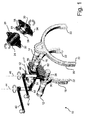
Die Figuren 1a und 1b zeigen eine perspektivische Ansicht der bevorzugten Ausführungsform einer erfindungsgemäßen Schaltgabelbetätigungsvorrichtung sowie Details der bevorzugten Ausführungsform der erfindungsgemäßen Schaltgabelbetätigungsvorrichtung. Die erfindungsgemäße Schaltgabelbetätigungsvorrichtung 10 weist drei parallel angeordnete Achsen auf. Zwei Achsen werden durch eine erste Schaltgabelstange 12 und eine zweite Schaltgabelstange 14 gebildet. Eine Lagerstange bildet die dritte Achse in Form einer Lagerachse 16. Die Schaltgabelstangen 12, 14 sind in nicht dargestellten Teilen eines Getriebegehäuses um ihre Achse drehbar und entlang ihrer Längsachse verschiebbar gelagert, die Lagerachse 16 ist entlang ihrer Längsachse verschiebbar. Die erste Schaltgabelstange 12 trägt eine erste Schaltgabel 18, die sich von der Längsachse der Lagerachse 16 weg erstreckt. Parallel zu der von der ersten Schaltgabel 18 gebildeten Ebene und ebenfalls von der Längsachse der Lagerachse 16 wegweisend erstreckt sich eine zweite Schaltgabel 20, die an einem freien Ende der zweiten Schaltgabelstange 14 angebracht ist. Die Schaltgabeln 18, 20 besitzen im Wesentlichen jeweils die Form eines Halbkreises und weisen an den Innenseiten ihrer Enden je ein Führungselement 22 auf. Diese greifen in nicht abgebildete Doppelschaltmuffen des Getriebes. Auf der Lagerachse 16 befinden sich das Mitnehmerteil 24 und das Blockierteil 26. Das Mitnehmerteil 24 sitzt konzentrisch auf der Lagerachse 16 und weist einen Führungsabschnitt 28 auf, dessen Oberfläche einen parallel zur Lagerachse ausgerichteten Polygonzylinder darstellt. Diese polygonförmige äußere Oberfläche des Führungsabschnitts 28 berührt die ebenfalls gleich ausgerichtete polygonzylinderförmige innere Oberfläche 30 des Blockierteils 26, das ebenfalls konzentrisch auf der Lagerachse 16 angeordnet ist. Das Mitnehmerteil 24 und das Blockierteil 26 können sich so axial relativ zueinander bewegen, sich aber nicht gegeneinander verdrehen. Das Blockierteil 26 kann also nur zusammen mit dem Mitnehmerteil eine Drehbewegung um die Lagerachse 16 ausführen. Anstatt der Polygonverbindung zwischen dem Mitnehmerteil 24 und dem Blockierteil 26 kann auch eine gleitende Feder gewählt werden. Das Mitnehmerteil 24 weist weiterhin eine erste Steuerkontur in Form einer Mitnehmersteuerkontur 32 auf und das Blockierteil 26 weist eine zweite Steuerkontur in Form einer Blockiersteuerkontur 34 auf. Die Mitnehmersteuerkontur 32 und die Blockiersteuerkontur 34 wirken mit entsprechenden Umfangsnuten der Steuergabelstangen 12, 14 zusammen. In dieser Abbildung zu sehen sind die Mitnehmerumfangsnut 36 und die Blockierumfangsnut 38 der ersten Steuergabelstange 12. Diese Nuten 36, 38 sind als Umfangsnuten in der ersten Steuergabelstange 12 vorgesehen. Des Weiteren sind in dieser Abbildung am Getriebeeingang zwei Drehhebel 40, 42 dargestellt, die um die Achse 44 beziehungsweise 46 gedreht werden können. Die Achsen 44, 46 sind senkrecht zu den durch die Schaltgabelstangen 12, 14 gebildeten Achsen und zur Längsachse der Lagerachse 16 angeordnet. Der Wählhebel 40 ist mit einer Wählhebelstange 48 drehfest verbunden, die ihrerseits drehbar um die Achse 44 gelagert ist. Die Wählhebelstange 48 wiederum weist einen drehfest mit ihr verbundenen Betätigungshebel 50 auf, der senkrecht zur Achse 44 und senkecht zum Wählhebel 40 angeordnet ist. Dieser Betätigungshebel betätigt eine Wählstange 52, die sich senkrecht zu den Achsen der Schaltgabelstangen 12, 14 und zur Längsachse der Lagerachse 16 sowie senkrecht zur Achse 44 beziehungsweise 46 erstreckt und in der aus den Schaltgabeln 18, 20 gebildeten Ebene liegt. Der Betätigungshebel 50 ist am Betätigungskopf 54 der Wählstange 52 angelenkt. Die Wählstange 52 ist entlang ihrer Achse verschiebbar gelagert. Sie weist an ihrer der Lagerachse 16 zugewandten Oberfläche eine Verzahnung 56 auf, die mit einem Verzahnungsabschnitt 58 des Blockierteils 26 in Eingriff steht. Der Verzahnungsabschnitt 58 ist an der oberen, den Schaltgabeln abgewandten Seite des Blockierteils 26 angeordnet. Alternativ kann anstelle der Verzahnung auch eine Kulissenführung oder ein Zwischenhebel mit Kugellager eingesetzt werden. Der Schalthebel 42 weist eine um die Achse 46 drehbare Schalthebelstange 60 auf und ist mit dieser drehfest an einem Ende der Schalthebelstange 60 verbunden. Das andere Ende der Schalthebelstange 60 ist mit einem Betätigungshebel 62 drehfest verbunden. Dieser erstreckt sich senkrecht zur Achse 46 und parallel zum Schalthebel 42 und kontaktiert den Führungsabschnitt 28 des Mitnehmerteils 24.Figures 1a and 1b show a perspective view of the preferred embodiment of a shift fork actuating device according to the invention as well as details of the preferred embodiment of the shift fork actuating device according to the invention. The shift
Im Betrieb gestaltet sich das Zusammenwirken der einzelnen Bauteile wie folgt: Die Drehbewegung der Hebel 40, 42 muss in eine lineare Bewegung einer der Schaltgabeln 18, 20 transformiert werden. Der Wählhebel 40 und der Schalthebel 42 übersetzen die mechanischen Eingangsignale, also die Wählrichtung und die Schaltrichtung zunächst in eine Drehbewegung. Die mechanischen Eingangssignale werden üblicherweise über ein Gestänge oder über einen Seilzug (beides hier nicht dargestellt) zum Getriebe übertragen. Wird an den Wählhebel 40 über eine derartige Anordnung ein Wählsignal übertragen, verdreht er dadurch die Wählhebelstange 48 um die Achse 44 um einen bestimmten Winkelbetrag. Diese Rotation wird bei dem Betätigungshebel 50 auf den Betätigungskopf 54 der Wählstange 52 übertragen. Diese wird also durch die Verdrehung des Wählhebels 40 in eine lineare Bewegung entlang ihrer eigenen Achse versetzt und betätigt wiederum über die Verzahnung 56 den Verzahnungsabschnitt 58 des Blockierteils 26. Dieses wiederum wird dadurch in eine Rotation um die Längsachse der Lagerstange 16 versetzt. Diese Rotation ändert die Winkelposition des Blockierteils 46 auf der Lagerstange 16. Dadurch gelangt beispielsweise die Blockiersteuerkontur 34 in Eingriff mit der Blockierumfangsnut 38 der ersten Schaltgabelstange 12, oder sie gibt beispielsweise die Umfangsnut 38 der ersten Schaltgabelstange 12 frei. Das Mitnehmerteil 24 und das Blockierteil 26 sind über die Polygonzylinderoberflächenabschnitte 28 und 30 drehfest bezüglich der Längsachse der Lagerachse 16 verbunden. Folglich vollführt das Mitnehmerteil 24 bei einer Drehung des Blockierteils 26 um die Längsachse der Lagerachse 16 eine Drehung in der gleichen Richtung und um den gleichen Winkelbetrag. Dies bewirkt komplementär zu den Auswirkungen einer Bewegung der Blockiersteuerkontur 34, dass die Mitnehmersteuerkontur 32 beispielsweise die Mitnehmerumfangsnut 36 der ersten Schaltgabelstange 12 freigibt oder mit der Mitnehmerumfangskontur 36 der Schaltgabelstange 12 in Eingriff gelangt. In analog komplementärer Weise verhalten sich die Steuerkonturen 32, 34 des Blockierteils 26 und des Mitnehmerteils 24 hinsichtlich der Umfangsnuten, die sich auf der Schaltgabelstange 14 befinden und in dieser Figur nicht einsehbar sind. Steuert ein mechanisches Eingangssignal den Schalthebel 42 an, so versetzt dieser die Schalthebelstange 60 in eine Rotation um die Achse 46. Daraufhin wird der Betätigungshebel 62 ebenfalls in Rotation um die Achse 46 versetzt und vermittelt diese Rotationsbewegung als lineare Bewegung an das Mitnehmerteil 24 entlang der durch die Lagerachse 16 definierten Achse.In operation, the interaction of the individual components designed as follows: The rotational movement of the
Das Blockierteil 26 weist weiterhin eine Führungsnase 64 auf, die in einer in dieser Figur nicht abgebildeten Nut des Getriebegehäuses geführt wird. Diese Nut erstreckt sich parallel zu der von den Schaltgabeln gebildeten Ebene und senkrecht zu der von der Lagerachse 16 definierten Achse. Dabei bewegt sich das Mitnehmerteil 24 relativ zum Blockierteil 26, dem eine axiale Bewegung entlang der Längsachse der Lagerachse 16 durch die in einer hier nicht dargestellten Gehäusenut geführten Führungsnase 64 verwehrt ist. Gleichzeitig nimmt das Mitnehmerteil 24 diejenige Schaltgabelstange 12, 14 bei dieser Bewegung mit, mit deren Umfangsnut es sich mit seiner Mitnehmersteuerkontur 32 in Eingriff befindet. Dabei vollführt die ausgewählte Schaltgabelstange (12 oder 14) eine Verschiebung entlang ihrer Längsachse und nimmt dabei wiederum die entsprechende Schaltgabel (18 oder 20) bei ihrer Bewegung mit. Dabei wird, durch die Führungselemente 22 vermittelt, die entsprechende Schaltmuffe des Getriebes eingestellt, d. h. eingerückt oder ausgerückt. Während die Wählbewegung unverstärkt zur Auswahl der richtigen Schaltgabel genutzt werden kann, ist für die Schaltbewegung eine Kraftverstärkung, beispielsweise durch einen Servozylinder, vorteilhaft. In diesem Fall kann dessen Kolbenstange die Lagerachse 16 bilden.The blocking
Bei einer Rotationsbewegung um eine durch die Lagerachse 16 definierten Achse gibt die Blockiersteuerkontur 34 des Blockierteils 26 beispielsweise die Schaltstange 14 an der Umfangsnut 72 frei. Gleichzeitig greift das Mitnehmerteil 24 mit seiner Mitnehmersteuerkontur in die Mitnehmerumfangsnut 70 der zweiten Schaltgabelstange 14. Wird nun an dem Schalthebel 42 eine Schaltbewegung eingeleitet, wird, über den Betätigungshebel 60 vermittelt, das Mitnehmerteil 24 entlang der durch die Lagerachse 16 definierten Achse bewegt. Dabei nimmt das Mitnehmerteil 24 die durch das Blockierteil 26 freigegebene und in Mitnahmeeingriff mit dem Mitnehmerteil 24 befindliche Schaltgabelstange 14 mit. Bei dieser Bewegung kann die Bewegung des Mitnehmerteils 24 durch einen Servozylinder unterstützt werden.During a rotational movement about an axis defined by the bearing
Das Zusammenwirken der Umfangsnuten 36, 38, 70, 72 der Schaltgabelstangen 12, 14 mit den Steuerkonturen des Blockierteils 26 und des Mitnehmerteils 24 sowie der Führungsnase 64 des Blockierteils 26 und des Einkerbungsabschnitts 80 des Mitnehmerteils 24 mit dem Gehäuse wird unter Bezug auf die
Im abgebildeten Zustand befindet sich das Mitnehmerteil 24 über seine Mitnehmersteuerkontur 32 in Eingriff mit der Umfangsnut 70 der Schaltgabelstange 14. Gleichzeitig gibt der sich in der Nähe der ersten Schaltgabelstange 12 befindliche erste Freigabeabschnitt 90 die erste Schaltgabelstange 12 frei. Dies hat zur Folge, dass bei einer axialen Bewegung des Mitnehmerteils 24, d. h. senkrecht zur Bildebene, die zweite Schaltgabelstange 14 und mit ihr die zweite Schaltgabel 20 dieser Bewegung entlang der Längsachse der Schaltgabelstange 14 folgen. Die erste Schaltgabelstange 12 und die mit ihr verbundene erste Schaltgabel 18 werden bei dieser Bewegung nicht bewegt. Führt nun das Mitnehmerteil 24, vermittelt durch den Drehhebel 40 und durch das Blockierteil 26, eine Rotationsbewegung gegen den Uhrzeigersinn um die durch die Lagerachse 16 definierte Achse aus, gibt der zweite Freigabeabschnitt 92 in einer bestimmten Drehposition die zweite Schaltgabelstange 14 frei und ermöglicht so eine Bewegung des Mitnehmerteils 24 entlang der Längsachse der Lagerachse 16, ohne die zweite Schaltgabelstange 14 mitzunehmen. Gleichzeitig gerät die Mitnehmersteuerkontur 32 in Eingriff mit der Umfangsnut 36 der ersten Schaltgabelstange 12 und ermöglicht so eine Mitnahme derselben entlang ihrer Längsachse, bei einer entsprechenden Bewegung des Mitnehmerteils 24.In the illustrated state, the
Bei einer Bewegung des Mitnehmerteils 24 relativ zu dem Blockierelement 26, die über die Polygonzylindergrenzflächen 28, 30 entlang der durch die Lagerachse 16 definierten Achse ermöglicht wird, wird eine unerwünschte Bewegung der ersten Schaltgabelstange 12 durch die Blockiersteuerkontur 34, die sich in Eingriff mit der Blockierumfangsnut 38 der ersten Schaltgabelstange 12 befindet, verhindert. Eine axiale Verschiebbarkeit des Blockierteils 26 selbst wird durch die Führungsnase 64, die sich in Eingriff mit einer im Gehäuse befindlichen Nut 82 befindet, verhindert. Bei einer Rotation des Mitnehmerteils 24 um die durch die Lagerachse 16 definierte Achse wird das Blockierteil 26 durch die Polygonzylinderoberflächen 28, 30 ebenfalls mitrotiert. Wird diese Rotation gegen den Uhrzeigersinn durchgeführt, gibt der erste Freigabeabschnitt 100 der Blockiersteuerkontur 34 die erste Schaltgabelstange 12 in einer bestimmten Winkelstellung frei. Gleichzeitig wird die Freigabe der zweiten Schaltgabelstange 14 durch den zweiten Freigabeabschnitt 102 aufgehoben und die Blockiersteuerkontur 34 gelangt in Eingriff mit der Blockierumfangsnut 72 der zweiten Schaltgabelstange 14. Auf diese Weise wird eine axiale Bewegung der ersten Schaltgabelstange 12 ermöglicht, während gleichzeitig eine derartige Bewegung der zweiten Schaltgabelstange 14 verhindert wird.Upon movement of the
Es ist im Betrieb der Schaltstangenbetätigungsvorrichtung 10 unter Umständen wünschenswert, die Schaltgabeln 18, 20 nur in entsprechenden Schaltpositionen zu schalten. Dazu dürfen bestimmte axiale Bewegungen des Mitnehmerteils 24 nur bei bestimmten Winkelpositionen ausführbar sein beziehungsweise bestimmte andere axiale Bewegungen sollen bei anderen bestimmten Winkelpositionen ermöglicht werden. Zu diesem Zweck sind im Gehäuse des Getriebes ein tieferer Steg 110 und ein flacherer Steg 112 angebracht. Die Steggeometrien entsprechen den Geometrien der Einkerbungen des Einkerbungsabschnitts 80 des Mitnehmerteils 24. Die Stege und die Einkerbungen bzw. Nuten sind so gegeneinander positioniert, dass sie nur bei einer entsprechenden Verdrehung des Mitnehmerteils 24 gekoppelt werden können. Bei bestimmten Schaltschemata ist es weiterhin auch erforderlich, die Schaltung in bestimmte Richtungen zu blockieren. Bei einer geeigneten Wahl der Steg- und Einkerbungsgeometrien verhindert beispielsweise der tiefere Steg 110 bei bestimmten Winkelpositionen des Mitnehmerteils 24 eine axiale Verschiebung des Mitnehmerteils 24 in Richtung des tieferen Stegs, wenn die Einkerbung des Einkerbungsabschnitts 80, die an dieser Winkelstellung um den tieferen Steg 110 greifen müsste, nicht die nötige Tiefe aufweist. Auf diese Weise lässt sich durch eine einfache konstruktive Maßnahme eine gezielte Einschränkung der Bewegungsfreiheit des Mitnehmerteils 24 erreichen.It may be desirable in the operation of the
Die in der vorstehenden Beschreibung, in den Zeichnungen sowie in den Ansprüchen offenbarten Merkmale der Erfindung können sowohl einzeln als auch in beliebiger Kombination für die Verwirklichung der Erfindung wesentlich sein.The features of the invention disclosed in the foregoing description, in the drawings and in the claims may be essential to the realization of the invention both individually and in any combination.
- 1010
- SchaltgabelbetätigungsvorrichtungShift fork actuator
- 1212
- erste Schaltgabelstangefirst shift fork rod
- 1414
- zweite Schaltgabelstangesecond shift fork rod
- 1616
- Lagerachsebearing axle
- 1818
- erste Schaltgabelfirst shift fork
- 2020
- zweite Schaltgabelsecond shift fork
- 2222
- Führungselementguide element
- 2424
- Mitnehmerteildriver part
- 2626
- Blockierteilblocking part
- 2828
- Führungsabschnittguide section
- 3030
- Führungsoberflächeguide surface
- 3232
- MitnehmersteuerkonturMitnehmersteuerkontur
- 3434
- BlockiersteuerkonturBlocking control contour
- 3636
- MitnehmerumfangsnutMitnehmerumfangsnut
- 3838
- BlockierumfangsnutBlockierumfangsnut
- 4040
- Wählhebelselector lever
- 4242
- Schalthebelgear lever
- 4444
- WählhebeldrehachseSelector lever axis of rotation
- 4646
- SchalthebeldrehachseLever axis of rotation
- 4848
- Wählhebelstangeshifter lever
- 5050
- Betätigungshebelactuating lever
- 5252
- WählstangeSelector Rod
- 5454
- Betätigungskopfactuating head
- 5656
- Verzahnunggearing
- 5858
- Verzahnungsabschnitttoothed section
- 6060
- Schalthebelstangeshifter rod
- 6262
- Betätigungshebelactuating lever
- 6464
- Führungsnaseguide nose
- 7070
- MitnehmerumfangsnutMitnehmerumfangsnut
- 7272
- BlockierumfangsnutBlockierumfangsnut
- 7474
- Lagerungstorage
- 8080
- Einkerbungsabschnittnotch
- 8282
- Führungsnutguide
- 9090
- erster Freigabeabschnittfirst release section
- 9292
- zweiter Freigabeabschnittsecond release section
- 100100
- erster Freigabeabschnittfirst release section
- 102102
- zweiter Freigabeabschnittsecond release section
- 110110
- tieferer Stegdeeper jetty
- 112112
- flacherer Stegflatter jetty
- A-AA-A
-
Schnittebene entlang der Lagerachse 16Cutting plane along the bearing
axis 16 - B-BB-B
-
Schnittebene durch das Mitnehmerteil 24 senkrecht zur Lagerachse 16Section plane through the
driver part 24 perpendicular to the bearing axis sixteenth - C-CC-C
-
Schnittebene durch das Blockierteil 26 senkrecht zur Lagerachse 16Cutting plane through the blocking
part 26 perpendicular to the bearing axis sixteenth
Claims (14)
- A gearshift fork activation device for optionally activating at least two gearshift forks (18, 20) of a gearbox, having blocking means for blocking a gearshift fork (18, 20) which is not to be activated and having driver means for driving a gearshift fork (18, 20), to be activated, in an axial direction, wherein the gearshift fork activation device has a bearing axle (16) which is arranged in the axial direction and which supports at least one blocking part (26) of the blocking means and at least one driver part (24) of the driver means, characterized in that the bearing axle (16) is formed by a piston rod (16), in particular by a piston rod (16) of a servo cylinder.
- A gearshift fork activation device as claimed in claim 1, characterized in that the driver part (24) has an external circumferential section with a first control contour (32) which is provided for interacting with circumferential contours (36, 70) of at least two gearshift fork rods (12, 14) which support the at least two gearshift forks (18, 20).
- A gearshift fork activation device as claimed in claim 1 or 2, characterized in that the blocking part (26) has an external circumferential section with a second control contour (34) which is provided for interacting with circumferential contours (38, 72) of at least two gearshift fork rods (12, 14) which support the at least two gearshift forks (18, 20).
- The gearshift fork activation device as claimed in one of the preceding claims, characterized in that the driver part (24) is arranged so as to be displaceable in the axial direction.
- The gearshift fork activation device as claimed in one of the preceding claims, characterized in that the bearing axle (16) supports the driver part (24) in such a way that it can carry out a rotational movement about the axial direction.
- The gearshift fork activation device as claimed in claim 2, characterized in that the first control contour (36, 70) drives the gearshift fork (18, 20) to be activated in the axial direction and at the same time does not act on the gearshift fork (18, 20) which is not to be activated.
- The gearshift fork activation device as claimed in one of the preceding claims, characterized in that the blocking part (26) is secured in the axial direction.
- The gearshift fork activation device as claimed in one of the preceding claims, characterized in that the bearing axle (16) supports the blocking part (26) in such a way that it can carry out a rotational movement about the axial direction.
- The gearshift fork activation device as claimed in claim 3, characterized in that the second control contour (34) blocks a movement of the gearshift fork (18, 20), which is not to be activated, in the axial direction and at the same time releases a movement of the gearshift fork (18, 20), which is to be activated, in the axial direction.
- The gearshift fork activation device as claimed in one of the preceding claims, characterized in that a rotational movement of the blocking part (26) about the axial direction is coupled to a rotational movement of the driver part (24) about the axial direction.
- The gearshift fork activation device as claimed in one of the preceding claims, characterized in that the driver part (24) and the blocking part (26) are arranged coaxially.
- The gearshift fork activation device as claimed in one of the preceding claims, characterized in that the driver part (24) has at least one groove (82).
- A gearbox, in particular motor vehicle gearbox, having a gearshift fork activation device (10) as claimed in one of claims 1 to 12.
- The gearbox as claimed in claim 13, characterized in that it is a manual or partially automatic change speed gearbox.
Applications Claiming Priority (2)
| Application Number | Priority Date | Filing Date | Title |
|---|---|---|---|
| DE102005000700A DE102005000700A1 (en) | 2005-01-04 | 2005-01-04 | Device for actuating shift forks |
| PCT/EP2006/000014 WO2006072567A1 (en) | 2005-01-04 | 2006-01-03 | Device for operating selector forks |
Publications (2)
| Publication Number | Publication Date |
|---|---|
| EP1836421A1 EP1836421A1 (en) | 2007-09-26 |
| EP1836421B1 true EP1836421B1 (en) | 2009-12-23 |
Family
ID=36032202
Family Applications (1)
| Application Number | Title | Priority Date | Filing Date |
|---|---|---|---|
| EP06700083A Not-in-force EP1836421B1 (en) | 2005-01-04 | 2006-01-03 | Device for operating selector forks |
Country Status (9)
| Country | Link |
|---|---|
| US (1) | US8079283B2 (en) |
| EP (1) | EP1836421B1 (en) |
| JP (1) | JP2008527261A (en) |
| CN (1) | CN101115940B (en) |
| AT (1) | ATE453072T1 (en) |
| BR (1) | BRPI0606516A2 (en) |
| DE (2) | DE102005000700A1 (en) |
| RU (1) | RU2007129832A (en) |
| WO (1) | WO2006072567A1 (en) |
Families Citing this family (13)
| Publication number | Priority date | Publication date | Assignee | Title |
|---|---|---|---|---|
| EP2053280B1 (en) * | 2007-10-23 | 2011-01-26 | Getrag Ford Transmissions GmbH | Method for attaining a neutral position of a shift fork in a gearbox |
| CN101660606B (en) * | 2009-09-21 | 2012-10-10 | 重庆大学 | Combined locking mechanism for shifting between master and slave boxes in mechanical transmission |
| DE102010026942B4 (en) * | 2010-07-12 | 2016-02-18 | Maschinenfabrik Mönninghoff Gmbh & Co. Kg | clutch |
| CN103348165B (en) * | 2011-02-03 | 2015-08-26 | 康斯博格汽车股份公司 | For being attached to the gearshift of gearbox |
| US20140165767A1 (en) * | 2012-12-19 | 2014-06-19 | Deere And Company | Manual synchronized gear shift assist |
| CN104227403B (en) * | 2014-08-25 | 2016-06-29 | 长城汽车股份有限公司 | Press-loading apparatus |
| KR101637693B1 (en) * | 2014-10-15 | 2016-07-08 | 현대자동차주식회사 | Shifting apparatus for manual transmission |
| USD790416S1 (en) * | 2015-03-27 | 2017-06-27 | RB Distribution, Inc. | Front wheel drive shift fork |
| FR3045765B1 (en) * | 2015-12-22 | 2018-01-19 | Psa Automobiles Sa. | GEARBOX FOR A MOTOR VEHICLE EQUIPPED WITH A PROVISIONAL IMMOBILIZATION PIECE OF THE CONTROL LEVER OF THIS BOX |
| DE102018216742A1 (en) * | 2018-09-28 | 2020-04-02 | Knorr-Bremse Systeme für Nutzfahrzeuge GmbH | Connection between a switching element and an aisle selector rod |
| DE102019220182B4 (en) * | 2019-12-19 | 2021-11-18 | Magna Pt B.V. & Co. Kg | Shift drum arrangement for a shifting device of a gear unit and gear unit for a drive train of a motor vehicle |
| WO2021146916A1 (en) * | 2020-01-21 | 2021-07-29 | Knorr-Bremse Braking Systems For Commercial Vehicles (Dalian) Co., Ltd. | Shifting device for a transmission |
| DE102022105952A1 (en) | 2022-03-15 | 2023-09-21 | Schaeffler Technologies AG & Co. KG | Hydraulic system and method for operating a hydraulic system |
Family Cites Families (7)
| Publication number | Priority date | Publication date | Assignee | Title |
|---|---|---|---|---|
| US1726132A (en) * | 1924-09-27 | 1929-08-27 | Int Motor Co | Transmission mechanism |
| US1774026A (en) * | 1928-12-07 | 1930-08-26 | Int Motor Co | Transmission control |
| US2157592A (en) * | 1935-06-25 | 1939-05-09 | Bendix Westinghouse Automotive | Gear shifting mechanism |
| US2137959A (en) * | 1936-01-03 | 1938-11-22 | Bendix Westinghouse Automotive | Gear shifting mechanism |
| GB948509A (en) * | 1961-06-14 | 1964-02-05 | Humber Ltd | Improvements in change-speed gear mechanisms |
| US4277983A (en) * | 1978-09-04 | 1981-07-14 | Honda Giken Kogyo Kabushiki Kaisha | Interlocking device for shift rod in power transmission |
| DE3409804A1 (en) * | 1983-03-17 | 1984-09-27 | Honda Giken Kogyo K.K., Tokio/Tokyo | SHIFTING MECHANISM IN AN ACTUATING ARRANGEMENT FOR A VEHICLE TRANSMISSION |
-
2005
- 2005-01-04 DE DE102005000700A patent/DE102005000700A1/en not_active Withdrawn
-
2006
- 2006-01-03 JP JP2007549853A patent/JP2008527261A/en not_active Withdrawn
- 2006-01-03 WO PCT/EP2006/000014 patent/WO2006072567A1/en active Application Filing
- 2006-01-03 BR BRPI0606516-3A patent/BRPI0606516A2/en not_active IP Right Cessation
- 2006-01-03 DE DE502006005723T patent/DE502006005723D1/en active Active
- 2006-01-03 EP EP06700083A patent/EP1836421B1/en not_active Not-in-force
- 2006-01-03 AT AT06700083T patent/ATE453072T1/en not_active IP Right Cessation
- 2006-01-03 CN CN2006800044605A patent/CN101115940B/en not_active Expired - Fee Related
- 2006-01-03 RU RU2007129832/11A patent/RU2007129832A/en not_active Application Discontinuation
-
2007
- 2007-07-05 US US11/822,381 patent/US8079283B2/en not_active Expired - Fee Related
Also Published As
| Publication number | Publication date |
|---|---|
| EP1836421A1 (en) | 2007-09-26 |
| DE102005000700A1 (en) | 2006-07-20 |
| US8079283B2 (en) | 2011-12-20 |
| BRPI0606516A2 (en) | 2009-06-30 |
| JP2008527261A (en) | 2008-07-24 |
| WO2006072567A1 (en) | 2006-07-13 |
| CN101115940A (en) | 2008-01-30 |
| RU2007129832A (en) | 2009-02-20 |
| CN101115940B (en) | 2012-07-04 |
| DE502006005723D1 (en) | 2010-02-04 |
| ATE453072T1 (en) | 2010-01-15 |
| US20080034912A1 (en) | 2008-02-14 |
Similar Documents
| Publication | Publication Date | Title |
|---|---|---|
| EP1836421B1 (en) | Device for operating selector forks | |
| EP2148998B1 (en) | Actuating device comprising a locking mechanism | |
| WO2006125608A1 (en) | Electric switching device for a motor vehicle | |
| DE2930151A1 (en) | GEAR SELECTION MECHANISM AND TRANSMISSION CONTAINING THIS | |
| DE102006005249B4 (en) | Transmission control device, manual transmission and method for performing a shift movement | |
| EP1836418B1 (en) | Shifting device for a vehicle transmission | |
| DE4137142A1 (en) | SWITCHING DEVICE FOR OEDIE SWITCHING ACTUATION OF MULTI-STAGE GEARBOXES FOR MOTOR VEHICLES | |
| EP2232107B1 (en) | Shifting arrangement for multi-stage manual transmissions of motor vehicles | |
| EP3096042A1 (en) | Transmission actuator for a motor vehicle transmission and control for actuating a transmission actuator | |
| WO2011069749A1 (en) | Mono-rail shifting device | |
| DE60109457T2 (en) | DEVICE FOR SEQUENTIAL MOTOR VEHICLE OPERATION WITH MANUAL CHOOSING AND LOADING GEARS | |
| EP3516271A2 (en) | Gear and gate (xy) gear actuator | |
| DE102015220466B3 (en) | Device for switching a transmission | |
| EP1711727B1 (en) | Gear-shifting device | |
| EP1917462B1 (en) | Shifting arrangement for displacing a selector fork | |
| WO2009071079A1 (en) | Actuating device having variable range of movement | |
| EP1291560B1 (en) | Power assisted gear shift device | |
| DE102013224263A1 (en) | Switching device of a multi-stage gearbox | |
| EP1673561A1 (en) | Shifting device | |
| EP3830452A1 (en) | Gear-shifting device for a transmission | |
| DE10217908A1 (en) | setting device | |
| EP2118531B1 (en) | Device for emergency disengagement of double-clutch gearboxes | |
| DE102006024487A1 (en) | Switching device for a gear change box of a motor vehicle comprises a switching shaft connected to electromotive moving units to support its axial movement and/or rotating movement | |
| WO2017076729A1 (en) | Transmission control device for an automated manual transmission of a vehicle |
Legal Events
| Date | Code | Title | Description |
|---|---|---|---|
| PUAI | Public reference made under article 153(3) epc to a published international application that has entered the european phase |
Free format text: ORIGINAL CODE: 0009012 |
|
| 17P | Request for examination filed |
Effective date: 20070806 |
|
| AK | Designated contracting states |
Kind code of ref document: A1 Designated state(s): AT BE BG CH CY CZ DE DK EE ES FI FR GB GR HU IE IS IT LI LT LU LV MC NL PL PT RO SE SI SK TR |
|
| DAX | Request for extension of the european patent (deleted) | ||
| 17Q | First examination report despatched |
Effective date: 20081223 |
|
| GRAP | Despatch of communication of intention to grant a patent |
Free format text: ORIGINAL CODE: EPIDOSNIGR1 |
|
| GRAS | Grant fee paid |
Free format text: ORIGINAL CODE: EPIDOSNIGR3 |
|
| GRAA | (expected) grant |
Free format text: ORIGINAL CODE: 0009210 |
|
| AK | Designated contracting states |
Kind code of ref document: B1 Designated state(s): AT BE BG CH CY CZ DE DK EE ES FI FR GB GR HU IE IS IT LI LT LU LV MC NL PL PT RO SE SI SK TR |
|
| REG | Reference to a national code |
Ref country code: GB Ref legal event code: FG4D Free format text: NOT ENGLISH |
|
| REG | Reference to a national code |
Ref country code: CH Ref legal event code: EP |
|
| REG | Reference to a national code |
Ref country code: IE Ref legal event code: FG4D |
|
| REF | Corresponds to: |
Ref document number: 502006005723 Country of ref document: DE Date of ref document: 20100204 Kind code of ref document: P |
|
| REG | Reference to a national code |
Ref country code: SE Ref legal event code: TRGR |
|
| REG | Reference to a national code |
Ref country code: NL Ref legal event code: VDEP Effective date: 20091223 |
|
| PG25 | Lapsed in a contracting state [announced via postgrant information from national office to epo] |
Ref country code: LT Free format text: LAPSE BECAUSE OF FAILURE TO SUBMIT A TRANSLATION OF THE DESCRIPTION OR TO PAY THE FEE WITHIN THE PRESCRIBED TIME-LIMIT Effective date: 20091223 Ref country code: FI Free format text: LAPSE BECAUSE OF FAILURE TO SUBMIT A TRANSLATION OF THE DESCRIPTION OR TO PAY THE FEE WITHIN THE PRESCRIBED TIME-LIMIT Effective date: 20091223 |
|
| LTIE | Lt: invalidation of european patent or patent extension |
Effective date: 20091223 |
|
| PG25 | Lapsed in a contracting state [announced via postgrant information from national office to epo] |
Ref country code: SI Free format text: LAPSE BECAUSE OF FAILURE TO SUBMIT A TRANSLATION OF THE DESCRIPTION OR TO PAY THE FEE WITHIN THE PRESCRIBED TIME-LIMIT Effective date: 20091223 Ref country code: PL Free format text: LAPSE BECAUSE OF FAILURE TO SUBMIT A TRANSLATION OF THE DESCRIPTION OR TO PAY THE FEE WITHIN THE PRESCRIBED TIME-LIMIT Effective date: 20091223 Ref country code: LV Free format text: LAPSE BECAUSE OF FAILURE TO SUBMIT A TRANSLATION OF THE DESCRIPTION OR TO PAY THE FEE WITHIN THE PRESCRIBED TIME-LIMIT Effective date: 20091223 |
|
| PGFP | Annual fee paid to national office [announced via postgrant information from national office to epo] |
Ref country code: IT Payment date: 20100126 Year of fee payment: 5 |
|
| REG | Reference to a national code |
Ref country code: IE Ref legal event code: FD4D |
|
| PG25 | Lapsed in a contracting state [announced via postgrant information from national office to epo] |
Ref country code: RO Free format text: LAPSE BECAUSE OF FAILURE TO SUBMIT A TRANSLATION OF THE DESCRIPTION OR TO PAY THE FEE WITHIN THE PRESCRIBED TIME-LIMIT Effective date: 20091223 Ref country code: IS Free format text: LAPSE BECAUSE OF FAILURE TO SUBMIT A TRANSLATION OF THE DESCRIPTION OR TO PAY THE FEE WITHIN THE PRESCRIBED TIME-LIMIT Effective date: 20100423 Ref country code: EE Free format text: LAPSE BECAUSE OF FAILURE TO SUBMIT A TRANSLATION OF THE DESCRIPTION OR TO PAY THE FEE WITHIN THE PRESCRIBED TIME-LIMIT Effective date: 20091223 Ref country code: BG Free format text: LAPSE BECAUSE OF FAILURE TO SUBMIT A TRANSLATION OF THE DESCRIPTION OR TO PAY THE FEE WITHIN THE PRESCRIBED TIME-LIMIT Effective date: 20100323 Ref country code: ES Free format text: LAPSE BECAUSE OF FAILURE TO SUBMIT A TRANSLATION OF THE DESCRIPTION OR TO PAY THE FEE WITHIN THE PRESCRIBED TIME-LIMIT Effective date: 20100403 Ref country code: NL Free format text: LAPSE BECAUSE OF FAILURE TO SUBMIT A TRANSLATION OF THE DESCRIPTION OR TO PAY THE FEE WITHIN THE PRESCRIBED TIME-LIMIT Effective date: 20091223 Ref country code: PT Free format text: LAPSE BECAUSE OF FAILURE TO SUBMIT A TRANSLATION OF THE DESCRIPTION OR TO PAY THE FEE WITHIN THE PRESCRIBED TIME-LIMIT Effective date: 20100423 |
|
| BERE | Be: lapsed |
Owner name: KNORR-BREMSE SYSTEME FUR NUTZFAHRZEUGE G.M.B.H. Effective date: 20100131 |
|
| PG25 | Lapsed in a contracting state [announced via postgrant information from national office to epo] |
Ref country code: CZ Free format text: LAPSE BECAUSE OF FAILURE TO SUBMIT A TRANSLATION OF THE DESCRIPTION OR TO PAY THE FEE WITHIN THE PRESCRIBED TIME-LIMIT Effective date: 20091223 Ref country code: MC Free format text: LAPSE BECAUSE OF NON-PAYMENT OF DUE FEES Effective date: 20100131 Ref country code: SK Free format text: LAPSE BECAUSE OF FAILURE TO SUBMIT A TRANSLATION OF THE DESCRIPTION OR TO PAY THE FEE WITHIN THE PRESCRIBED TIME-LIMIT Effective date: 20091223 |
|
| PGFP | Annual fee paid to national office [announced via postgrant information from national office to epo] |
Ref country code: SE Payment date: 20100118 Year of fee payment: 5 |
|
| REG | Reference to a national code |
Ref country code: CH Ref legal event code: PL |
|
| PG25 | Lapsed in a contracting state [announced via postgrant information from national office to epo] |
Ref country code: IE Free format text: LAPSE BECAUSE OF FAILURE TO SUBMIT A TRANSLATION OF THE DESCRIPTION OR TO PAY THE FEE WITHIN THE PRESCRIBED TIME-LIMIT Effective date: 20091223 Ref country code: CH Free format text: LAPSE BECAUSE OF NON-PAYMENT OF DUE FEES Effective date: 20100131 Ref country code: CY Free format text: LAPSE BECAUSE OF FAILURE TO SUBMIT A TRANSLATION OF THE DESCRIPTION OR TO PAY THE FEE WITHIN THE PRESCRIBED TIME-LIMIT Effective date: 20091223 Ref country code: GR Free format text: LAPSE BECAUSE OF FAILURE TO SUBMIT A TRANSLATION OF THE DESCRIPTION OR TO PAY THE FEE WITHIN THE PRESCRIBED TIME-LIMIT Effective date: 20100324 Ref country code: LI Free format text: LAPSE BECAUSE OF NON-PAYMENT OF DUE FEES Effective date: 20100131 |
|
| PLBE | No opposition filed within time limit |
Free format text: ORIGINAL CODE: 0009261 |
|
| STAA | Information on the status of an ep patent application or granted ep patent |
Free format text: STATUS: NO OPPOSITION FILED WITHIN TIME LIMIT |
|
| GBPC | Gb: european patent ceased through non-payment of renewal fee |
Effective date: 20100323 |
|
| 26N | No opposition filed |
Effective date: 20100924 |
|
| PG25 | Lapsed in a contracting state [announced via postgrant information from national office to epo] |
Ref country code: DK Free format text: LAPSE BECAUSE OF FAILURE TO SUBMIT A TRANSLATION OF THE DESCRIPTION OR TO PAY THE FEE WITHIN THE PRESCRIBED TIME-LIMIT Effective date: 20091223 |
|
| PG25 | Lapsed in a contracting state [announced via postgrant information from national office to epo] |
Ref country code: BE Free format text: LAPSE BECAUSE OF NON-PAYMENT OF DUE FEES Effective date: 20100131 |
|
| PG25 | Lapsed in a contracting state [announced via postgrant information from national office to epo] |
Ref country code: GB Free format text: LAPSE BECAUSE OF NON-PAYMENT OF DUE FEES Effective date: 20100323 |
|
| REG | Reference to a national code |
Ref country code: FR Ref legal event code: ST Effective date: 20110228 |
|
| PG25 | Lapsed in a contracting state [announced via postgrant information from national office to epo] |
Ref country code: FR Free format text: LAPSE BECAUSE OF NON-PAYMENT OF DUE FEES Effective date: 20100223 |
|
| REG | Reference to a national code |
Ref country code: SE Ref legal event code: EUG |
|
| PG25 | Lapsed in a contracting state [announced via postgrant information from national office to epo] |
Ref country code: IT Free format text: LAPSE BECAUSE OF NON-PAYMENT OF DUE FEES Effective date: 20110103 |
|
| REG | Reference to a national code |
Ref country code: AT Ref legal event code: MM01 Ref document number: 453072 Country of ref document: AT Kind code of ref document: T Effective date: 20110103 |
|
| PG25 | Lapsed in a contracting state [announced via postgrant information from national office to epo] |
Ref country code: LU Free format text: LAPSE BECAUSE OF NON-PAYMENT OF DUE FEES Effective date: 20100103 Ref country code: HU Free format text: LAPSE BECAUSE OF FAILURE TO SUBMIT A TRANSLATION OF THE DESCRIPTION OR TO PAY THE FEE WITHIN THE PRESCRIBED TIME-LIMIT Effective date: 20100624 |
|
| PG25 | Lapsed in a contracting state [announced via postgrant information from national office to epo] |
Ref country code: TR Free format text: LAPSE BECAUSE OF FAILURE TO SUBMIT A TRANSLATION OF THE DESCRIPTION OR TO PAY THE FEE WITHIN THE PRESCRIBED TIME-LIMIT Effective date: 20091223 |
|
| PG25 | Lapsed in a contracting state [announced via postgrant information from national office to epo] |
Ref country code: AT Free format text: LAPSE BECAUSE OF NON-PAYMENT OF DUE FEES Effective date: 20110103 |
|
| PG25 | Lapsed in a contracting state [announced via postgrant information from national office to epo] |
Ref country code: SE Free format text: LAPSE BECAUSE OF NON-PAYMENT OF DUE FEES Effective date: 20110104 |
|
| PGFP | Annual fee paid to national office [announced via postgrant information from national office to epo] |
Ref country code: DE Payment date: 20180124 Year of fee payment: 13 |
|
| REG | Reference to a national code |
Ref country code: DE Ref legal event code: R119 Ref document number: 502006005723 Country of ref document: DE |
|
| PG25 | Lapsed in a contracting state [announced via postgrant information from national office to epo] |
Ref country code: DE Free format text: LAPSE BECAUSE OF NON-PAYMENT OF DUE FEES Effective date: 20190801 |