EP1836412B1 - Device for installing and removing a belt and method for installing and removing a belt respectively - Google Patents
Device for installing and removing a belt and method for installing and removing a belt respectively Download PDFInfo
- Publication number
- EP1836412B1 EP1836412B1 EP06709398A EP06709398A EP1836412B1 EP 1836412 B1 EP1836412 B1 EP 1836412B1 EP 06709398 A EP06709398 A EP 06709398A EP 06709398 A EP06709398 A EP 06709398A EP 1836412 B1 EP1836412 B1 EP 1836412B1
- Authority
- EP
- European Patent Office
- Prior art keywords
- belt
- cylindrical body
- pulley
- shaped device
- annular neck
- Prior art date
- Legal status (The legal status is an assumption and is not a legal conclusion. Google has not performed a legal analysis and makes no representation as to the accuracy of the status listed.)
- Active
Links
Images

Classifications
-
- F—MECHANICAL ENGINEERING; LIGHTING; HEATING; WEAPONS; BLASTING
- F16—ENGINEERING ELEMENTS AND UNITS; GENERAL MEASURES FOR PRODUCING AND MAINTAINING EFFECTIVE FUNCTIONING OF MACHINES OR INSTALLATIONS; THERMAL INSULATION IN GENERAL
- F16H—GEARING
- F16H7/00—Gearings for conveying rotary motion by endless flexible members
- F16H7/24—Equipment for mounting belts, ropes, or chains
Definitions
- the invention relates to the assembly and disassembly of a belt in a cylindrical body of revolution such as a pulley.
- the invention is particularly applicable to the installation and removal of belts used in motor vehicles.
- a flexible transmission means such as a belt or a chain.
- This belt or chain must be tensioned, for example by means of a tensioner.
- This tensioner can be fixed, and then adjusted after the installation of the belt or chain is dynamic, to allow a variation of the voltage depending on the work that is performed by the machine.
- an action on it allows to release the stress of tension exerted on the belt or chain to allow the introduction - or removal - thereof.
- this object is achieved by a U-shaped device suitable for fitting the groove laterally so that one of the branches of the U temporarily covers a circumferential sector of the pulley.
- the device is not intended to ride the pulley so that the base of the U covers a circumferential sector but to be placed laterally, the covering area being constituted by one of the branches of the U.
- the two cheeks are movable relative to each other and are associated at the base of the U, by at least one tenon.
- the device according to the invention also makes it possible to modify the path of the belt so as to pull it out of the annular groove in which it is housed in order to mount it at the circumference of the cylindrical body. Once mounted at this radial level, the belt can be moved axially to remove it.
- the device according to the invention is particularly intended for garages and is adapted to interventions on the so-called transmission belt that connects the crankshaft to the valve control shaft or the so-called accessory belt. For as much, it can also find application for the assembly or disassembly of any belt in a ring groove.
- the term "cylindrical body of revolution” means both pulleys that axes or rods having an annular groove for housing the belt when it is placed.
- the object of the invention is also achieved by a method of laying a belt on the annular groove of a cylindrical body comprising the introduction of a U-shaped device for covering the annular groove on a circumferential sector of the cylindrical body using one of the branches of the U, the engagement of the belt on said limb and on another cylindrical body intended to be connected to the first by the belt, the alignment of the belt on the annular grooves of the two bodies cylindrical, the rotation of the cylindrical bodies until the branch of the U-shaped device is disengaged from the belt and the withdrawal of the U-shaped device.
- the invention also relates to a method of depositing a belt housed in the annular groove of cylindrical bodies of revolution comprising the introduction of a U-shaped device, so that one of the branches of the U covers the annular groove. on a circumferential sector of the cylindrical body not occupied by the belt, the rotation of the cylindrical bodies until the belt is engaged on said leg of the U, the removal of the belt and the withdrawal of the U-shaped device.
- the methods respectively of laying or depositing a belt according to the invention are implemented using a device for laying and for depositing a belt as described above.
- the invention thus allows the installation and removal of elastic belts without damaging them and with a stretch remaining largely within the elastic limits. Thus, it is no longer necessary, at each occasion of removal of a belt, to replace it with a new belt.
- each type of elastic belt can cover a wider range of belt transmission architectures, which makes this invention solution also very economical and in particular standard.
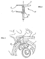
- FIG. 1 shows, in section, a device according to a first variant of the invention not claimed
- the figure 2 shows, in perspective, the device of the figure 1 when laying a belt on a pulley
- the figure 3 shows in perspective, a device according to the invention.
- the device is intended to allow the mounting of an elastic belt C in the groove of a perforated pulley 1 as illustrated. figure 1 .
- the device has the general shape of a U-shaped tool and comprises two cheeks 4 and 5.
- the cheek 4 - still called cover cheek comes temporarily cover a circumferential sector of the groove of the pulley.
- “Temporarily” means: for the installation or removal of the belt.
- the cheek 4 is made in one piece in the shape of an L.
- the cheek 5 represented in FIGS. Figures 1 and 2 is T-shaped, with a retaining tab 9 which makes it possible to prevent the belt C, when it has emerged from the groove of the pulley, from being pushed for example between the pulley and the machine on which the pulley is mounted .
- the two cheeks are mounted movable relative to each other on a rod 61.
- this rod is at least partially threaded and is part of a clamping means 6 which also belongs to a wheel 64 engaged on the rod 61.
- the wheel 64 can be replaced for example by a traditional hexagonal nut or a wing nut.
- the length of the rod is determined so as to ensure a sufficiently long stroke to the wheel to be able to perform the clamping function within the predetermined spacing of the flanges 4, 5.
- the cheek 4 is like the cheek 5 L-shaped, the base of the U being relatively enlarged.
- This variant allows housing in the base not only a threaded rod but also at least one pin 62, associated with the cheek 5 which cooperates with a housing provided in the cheek 4.
- the tenon can be replaced by a sliding rod, in which case a housing will also be provided in the cheek 5.
- the device according to the invention has the advantage of being able to be used for many pulleys within a range of predetermined diameters and widths.
- the cheek 4 has a substantially flat outer surface or, preferably, curved. This cheek 4 forms a stable support for the belt, regardless of the spacing of the cheeks.
- the length of the outer surface of the cheek 4, in the direction of the periphery of the pulley, can be determined so as to cover a circumferential sector of the pulley of the order of 10 ° to 20 °. When the outer surface is curved, the radius of this curvature may correspond approximately to the radius of the pulley.
- the device 10 may exert harmful forces on the belt C by the front and rear edges, in the direction of the periphery of the pulley, at the moment when the device pushes the belt towards the outside.
- the radius defining the curvature of the bearing surface 34 of the device 10 is less than the radius of the pulley, an order of magnitude of 10 to 15%, the central portion of this surface may exert very large forces on the belt when it is pushed outward.
- the method of laying a belt on a cylindrical body of revolution will be implemented. the following way: the annular groove of a cylindrical body 1 is covered over a circumferential sector thereof by means of a cheek 4 by installing a tool 10; the cylindrical body 1 chosen is generally one of the cylindrical bodies to be connected by the belt, which has the largest diameter; however, one can also choose another cylindrical body among them without departing from the principle of the present invention.
- a belt C is then engaged on the outer surface of the cheek 4 and on the other cylindrical body (s) intended to be connected (s) to the first cylindrical body by the belt.
- the belt is aligned on the annular grooves 2 of the cylindrical bodies to be connected and the cylindrical bodies are rotated until the cover flap 4 is released from the belt and withdraws the tool to disengage the annular groove.
- the method of removing a belt from a cylindrical body of revolution will be implemented in the following manner: the annular groove 2 is covered with a first cylindrical body 1 connected to another cylindrical body by a belt C, on a circumferential sector not occupied by the belt, using a cheek 4. The cylindrical body 1 is rotated until the belt is engaged on the cover cheek 4. The belt is removed from the belt cheek 4 and remove or retract the cheek 4.
Abstract
Description
L'invention concerne le montage et le démontage d'une courroie dans un corps cylindrique de révolution tel une poulie. L'invention s'applique tout particulièrement aux opérations de pose et de dépose des courroies utilisées dans des véhicules automobiles.The invention relates to the assembly and disassembly of a belt in a cylindrical body of revolution such as a pulley. The invention is particularly applicable to the installation and removal of belts used in motor vehicles.
Dès lors qu'une machine comporte au moins deux arbres dont l'un est doit entraîner l'autre, il est courant d'utiliser un moyen de transmission flexible, comme une courroie ou une chaîne. Cette courroie ou cette chaîne doit être mise en tension, par exemple au moyen d'un tendeur. Ce tendeur peut être fixe, et alors réglé après la pose de la courroie ou de la chaîne soit dynamique, pour permettre une variation de la tension en fonction du travail qui est effectué par la machine. Pour toute machine équipée d'un tendeur, une action sur celui-ci permet de libérer la contrainte de tension exercée sur la courroie ou la chaîne pour permettre la mise en place - ou la dépose - de celle-ci.Since a machine has at least two shafts one of which is to drive the other, it is common to use a flexible transmission means, such as a belt or a chain. This belt or chain must be tensioned, for example by means of a tensioner. This tensioner can be fixed, and then adjusted after the installation of the belt or chain is dynamic, to allow a variation of the voltage depending on the work that is performed by the machine. For any machine equipped with a tensioner, an action on it allows to release the stress of tension exerted on the belt or chain to allow the introduction - or removal - thereof.
Il est également possible de se dispenser du tendeur en recourant à des courroies élastiques qui sont montées par mises en extension. Même si la suppression du tendeur représente un avantage important, l'utilisation de telles courroies élastiques n'est pas non plus sans poser problème. En effet, l'étirement maximum autorisé sous peine de rupture - ou à tout le moins de dégradation de la courroie - est relativement faible, de sorte que les opérations de pose - et de dépose - sont risquées, le risque augmentant en général avec le nombre de poulies reliées par la courroie.It is also possible to dispense with the tensioner by using elastic belts that are mounted by extension. Although the removal of the tensioner is an important advantage, the use of such elastic belts is also not a problem. Indeed, the maximum stretch allowed under penalty of breakage - or at least of degradation of the belt - is relatively low, so that the operations of installation - and removal - are risky, the risk increasing in general with the number of pulleys connected by the belt.
Il doit de plus être souligné que ce risque est d'autant plus grand que la pose - ou la dépose - sont réalisées non sur une ligne traditionnelle de montage mais dans un atelier d'entretien, les garagistes ne pouvant pas disposer d'outils optimisés pour tous les véhicules dont ils assurent l'entretien.It should also be emphasized that this risk is even greater than the installation - or removal - are performed not on a traditional assembly line but in a maintenance workshop, garages can not have optimized tools for all the vehicles they maintain.
En fait, même avec un montage classique avec un tendeur, il est toujours relativement délicat de monter une courroie sur un corps cylindrique tel une poulie, car la jante comportant une gorge annulaire d'entraînement, les bords de la jante constituent souvent des pièces coupantes qui peuvent trancher la courroie si des précautions ne sont pas prises au montage.In fact, even with a conventional assembly with a tensioner, it is still relatively difficult to mount a belt on a cylindrical body such as a pulley, because the rim having an annular drive groove, the edges of the rim are often sharp parts who can slice the belt if precautions are not taken during assembly.
C'est pourquoi différents outillages spécifiques ont été développés. Ainsi, la demande de brevet français
Le document
The document
Il subsiste donc un besoin d'un outil de maniement simple et surtout particulièrement adapté pour la dépose d'une courroie - notamment mais non exclusivement une courroie élastique - sur un corps cylindrique, comme par exemple une poulie.There remains therefore a need for a simple handling tool and especially particularly suitable for the removal of a belt - particularly but not exclusively an elastic belt - on a cylindrical body, such as a pulley.
Selon l'invention, ce but est atteint par un dispositif en U apte à chausser la gorge latéralement de sorte que l'une des branches du U couvre temporairement un secteur circonférentiel de la poulie.According to the invention, this object is achieved by a U-shaped device suitable for fitting the groove laterally so that one of the branches of the U temporarily covers a circumferential sector of the pulley.
Conformément à l'invention, le dispositif n'est donc pas destiné à enfourcher la poulie de sorte que la base du U recouvre un secteur circonférentiel mais à être placé latéralement, la zone de recouvrement étant constituée par une des branches du U.According to the invention, the device is not intended to ride the pulley so that the base of the U covers a circumferential sector but to be placed laterally, the covering area being constituted by one of the branches of the U.
Dans l'invention, les deux joues sont mobiles l'une par rapport à l'autre et sont associées au niveau de la base du U, par au moins un tenon.In the invention, the two cheeks are movable relative to each other and are associated at the base of the U, by at least one tenon.
Ceci revient donc à dissocier la fonction de support de la courroie lors de la pose (et la dépose) de la fonction d'ajustement de l'outil à la taille de la poulie. Comme la courroie ne repose à aucun moment sur la base du U, il est possible qu'un espace subsiste entre les deux branches (cas d'une poulie à jante large) sans que la fonction de guidage de la courroie ne soit en rien affectée.This amounts to dissociating the support function of the belt during the installation (and removal) of the function of adjustment of the tool to the size of the pulley. As the belt does not rest at any time on the base of the U, it is possible that a space remains between the two branches (case of a pulley with wide rim) without the function of guiding the belt is not affected in any way .
Le dispositif selon l'invention permet également de modifier le chemin de la courroie de manière à la faire sortir de la gorge annulaire dans laquelle elle est logée pour la monter à la circonférence du corps cylindrique. Une fois montée à ce niveau radial, la courroie peut être déplacée axialement pour la déposer.The device according to the invention also makes it possible to modify the path of the belt so as to pull it out of the annular groove in which it is housed in order to mount it at the circumference of the cylindrical body. Once mounted at this radial level, the belt can be moved axially to remove it.
Le dispositif selon l'invention est tout particulièrement destiné aux garagistes et est adapter aux interventions sur la courroie dite de transmission qui relie le vilebrequin à l'arbre de commande des soupapes ou encore sur la courroie dites accessoires. Pour autant, il peut également trouver application pour le montage ou le démontage de toute courroie dans une gorge annulaire. Ainsi, le terme "corps cylindrique de révolution" désigne aussi bien des poulies que des axes ou tiges comportant une gorge annulaire destinée à loger la courroie lorsqu'elle est posée.The device according to the invention is particularly intended for garages and is adapted to interventions on the so-called transmission belt that connects the crankshaft to the valve control shaft or the so-called accessory belt. For as much, it can also find application for the assembly or disassembly of any belt in a ring groove. Thus, the term "cylindrical body of revolution" means both pulleys that axes or rods having an annular groove for housing the belt when it is placed.
Le but de l'invention est également atteint par un procédé de pose d'une courroie sur la gorge annulaire d'un corps cylindrique comportant la mise en place d'un dispositif en U pour recouvrir la gorge annulaire sur un secteur circonférentiel du corps cylindrique à l'aide d'une des branches du U, l'engagement de la courroie sur ladite branche et sur un autre corps cylindrique destiné à être relié au premier par la courroie, l'alignement de la courroie sur les gorges annulaires des deux corps cylindriques, la rotation des corps cylindriques jusqu'à ce que la branche du dispositif en U soit dégagée de la courroie et le retrait du dispositif en U.The object of the invention is also achieved by a method of laying a belt on the annular groove of a cylindrical body comprising the introduction of a U-shaped device for covering the annular groove on a circumferential sector of the cylindrical body using one of the branches of the U, the engagement of the belt on said limb and on another cylindrical body intended to be connected to the first by the belt, the alignment of the belt on the annular grooves of the two bodies cylindrical, the rotation of the cylindrical bodies until the branch of the U-shaped device is disengaged from the belt and the withdrawal of the U-shaped device.
Corollairement, l'invention concerne également un procédé de dépose d'une courroie logée dans la gorge annulaire de corps cylindriques de révolution comportant la mise en place d'un dispositif en U, de sorte qu'une des branches du U recouvre la gorge annulaire sur un secteur circonférentiel du corps cylindrique non occupé par la courroie, la rotation des corps cylindriques jusqu'à ce que la courroie soit engagée sur ladite branche du U, l'enlèvement de la courroie et le retrait du dispositif en U.As a corollary, the invention also relates to a method of depositing a belt housed in the annular groove of cylindrical bodies of revolution comprising the introduction of a U-shaped device, so that one of the branches of the U covers the annular groove. on a circumferential sector of the cylindrical body not occupied by the belt, the rotation of the cylindrical bodies until the belt is engaged on said leg of the U, the removal of the belt and the withdrawal of the U-shaped device.
Avantageusement, les procédés respectivement de poser ou de déposer une courroie selon l'invention sont mis en oeuvre à l'aide d'un dispositif pour poser et pour déposer une courroie tel que décrit plus haut.Advantageously, the methods respectively of laying or depositing a belt according to the invention are implemented using a device for laying and for depositing a belt as described above.
L'invention permet ainsi la pose et la dépose de courroies élastiques sans les endommager et avec un étirement restant largement à l'intérieur des limites d'élasticité. Ainsi, il n'est plus nécessaire, à chaque occasion de dépose d'une courroie, de la remplacer par une nouvelle courroie. De plus, chaque type de courroie élastique peut couvrir une gamme plus large d'architectures de transmission par courroie, ce qui rend cette solution de invention aussi très économique et notamment standard.The invention thus allows the installation and removal of elastic belts without damaging them and with a stretch remaining largely within the elastic limits. Thus, it is no longer necessary, at each occasion of removal of a belt, to replace it with a new belt. In addition, each type of elastic belt can cover a wider range of belt transmission architectures, which makes this invention solution also very economical and in particular standard.
D'autres caractéristiques et avantages de la présente invention ressortiront de la description ci-après de trois modes de réalisation du dispositif de l'invention et d'une description de la mise en oeuvre du dispositif. Ces descriptions sont faites en référence aux dessins dans lesquels :Other features and advantages of the present invention will emerge from the following description of three embodiments of the device of the invention and a description of the implementation of the device. These descriptions are made with reference to the drawings in which:
la
la
la
Le dispositif est destiné à permettre le montage d'une courroie élastique C dans la gorge d'une poulie ajourée 1 comme illustré
La joue 4 est réalisée en une seule pièce en forme de L. La joue 5 représentée aux
Les deux joues sont montées mobiles l'une par rapport à l'autre sur une tige 61. Dans la variante ici représentée, cette tige est au moins partiellement filetée et fait partie d'un moyen de serrage 6 auquel appartient également une molette 64 engagée sur la tige 61. La molette 64 peut être remplacée par exemple par un écrou traditionnel à six pans ou par un écrou à oreilles. La longueur de la tige est déterminée de manière à assurer une course suffisamment longue à la molette pour pouvoir exercer la fonction de serrage dans les limites d'espacement prédéterminées des joues 4, 5.The two cheeks are mounted movable relative to each other on a
Dans la variante de l'invention, illustrée
Le dispositif selon l'invention présente l'avantage de pouvoir être utilisé pour de nombreuses poulies à l'intérieur d'une gamme de diamètres et de largeurs prédéterminée. En effet, la joue 4 présente une surface extérieure sensiblement plane ou, de préférence, courbe. Cette joue 4 forme un support stable pour la courroie, quel que soit l'écartement des joues. La longueur de la surface extérieure de la joue 4, dans le sens du pourtour de la poulie, peut être déterminée de manière à pouvoir couvrir un secteur circonférentiel de la poulie de l'ordre de 10° à 20° environ. Lorsque la surface extérieure est courbe, le rayon de cette courbure peut correspondre approximativement au rayon de la poulie. Lorsque le rayon définissant la courbure de la surface extérieure 34 de l'élément de couverture 3 dépasse le rayon de la poulie d'un ordre de grandeur de 10 %, le dispositif 10 risque d'exercer des efforts nuisibles sur la courroie C par les bords avant et arrière, dans le sens du pourtour de la poulie, au moment ou le dispositif pousse la courroie vers l'extérieur. En contrepartie, lorsque le rayon définissant la courbure de la surface d'appui 34 du dispositif 10 est inférieure au rayon de la poulie, d'un ordre de grandeur de 10 à 15 %, la partie centrale de cette surface risque d'exercer des efforts très grands sur la courroie au moment où celle-ci est poussée vers l'extérieur.The device according to the invention has the advantage of being able to be used for many pulleys within a range of predetermined diameters and widths. Indeed, the
Quel que soit le mode de réalisation choisi du dispositif de invention ou quelle que soit la variante décrite plus haut ou ressortant aisément à la lecture de cette description, le procédé de pose d'une courroie sur un corps cylindrique de révolution sera mis en oeuvre de la manière suivante : on couvre la gorge annulaire d'un corps cylindrique 1 sur un secteur circonférentiel de celui-ci à l'aide d'une joue 4 en installant un outil 10; le corps cylindrique 1 choisi est en général celui parmi les corps cylindriques à relier par la courroie, qui présente le plus grand diamètre ; toutefois, on peut également choisir un autre corps cylindrique parmi ceux-ci sans sortir du principe de la présente invention. On engage ensuite une courroie C sur la surface extérieure de la joue 4 et sur le (ou les) autre(s) corps cylindrique(s) destiné(s) à être relié(s) au premier corps cylindrique par la courroie. On aligne la courroie sur les gorges annulaires 2 des corps cylindriques à relier et on fait tourner les corps cylindriques jusqu'à ce que la joue de couverture 4 soit dégagée de la courroie et retire l'outil pour dégager la gorge annulaire.Whatever the embodiment chosen of the device of the invention or whatever variant described above or readily apparent from reading this description, the method of laying a belt on a cylindrical body of revolution will be implemented. the following way: the annular groove of a cylindrical body 1 is covered over a circumferential sector thereof by means of a
De manière correspondante, le procédé de dépose d'une courroie d'un corps cylindrique de révolution sera mis en oeuvre de la manière suivante : on recouvre la gorge annulaire 2 d'un premier corps cylindriques 1 relié à un autre corps cylindrique par une courroie C, sur un secteur circonférentiel non occupé par la courroie, à l'aide d'une joue 4. On fait tourner le corps cylindrique 1 jusqu'à ce que la courroie soit engagée sur la joue de couverture 4. On enlève la courroie de la joue 4 et on retire ou escamote la joue 4.Correspondingly, the method of removing a belt from a cylindrical body of revolution will be implemented in the following manner: the annular groove 2 is covered with a first cylindrical body 1 connected to another cylindrical body by a belt C, on a circumferential sector not occupied by the belt, using a
Claims (5)
- A device (10) for laying down and taking up a belt (C) on a cylindrical body (1) of revolution comprising an apertured rim and an annular neck for accommodating the belt which is laid down, this device consisting of a U-shape having two flanges (4, 5) for fitting to the side of the neck so that the flange (4) or covering flange (4) temporarily covers the annular neck on a circumferential sector of the cylindrical body, the two flanges being movable with respect to one another and having an L-shape and being connected at the bottom of the U by at least one tenon (62).
- The device according to claim 1, characterised in that it comprises at least one sliding rod (7) and clamping means (6).
- The device according to any of the preceding claims, characterised in that the covering branch (4) comprises a curved outside surface.
- A method for laying down a belt on a cylindrical body comprising an annular neck for accommodating the belt being laid down, comprising the following steps:a) positioning a U-shaped device (10) so as to cover the annular neck on a circumferential sector of the cylindrical body with one of the branches of the U;b) engaging the belt (C) on said branch and on another cylindrical body which is to be connected to the first body by the belt,c) aligning the belt (C) on the annular necks (2) of the two cylindrical bodies (1),d) rotating the cylindrical bodies (1) until the branch of the U-shaped device is disengaged from the belt; ande) withdrawing the U-shaped device (10).
- A method for taking up a belt accommodated in the annular neck (2) of a cylindrical body of revolution, comprising the following steps:a) positioning a U-shaped device (10) so that one of the branches of the U covers the annular neck (2) on a circumferential sector of the cylindrical body (1) not occupied by the belt,b) rotating the cylindrical bodies (1) until the belt (C) is engaged on said branch of the U;c) removing the belt (C); andd) withdrawing the U-shaped device (10).
Applications Claiming Priority (2)
| Application Number | Priority Date | Filing Date | Title |
|---|---|---|---|
| FR0500271A FR2880572B1 (en) | 2005-01-11 | 2005-01-11 | DEVICE FOR LAYING AND REMOVING A BELT AND METHOD RESPECTIVELY FOR THE INSTALLATION AND REMOVAL OF A BELT |
| PCT/FR2006/050010 WO2006075113A1 (en) | 2005-01-11 | 2006-01-10 | Device for installing and removing a belt and method for installing and removing a belt respectively |
Publications (2)
| Publication Number | Publication Date |
|---|---|
| EP1836412A1 EP1836412A1 (en) | 2007-09-26 |
| EP1836412B1 true EP1836412B1 (en) | 2011-06-22 |
Family
ID=34953448
Family Applications (1)
| Application Number | Title | Priority Date | Filing Date |
|---|---|---|---|
| EP06709398A Active EP1836412B1 (en) | 2005-01-11 | 2006-01-10 | Device for installing and removing a belt and method for installing and removing a belt respectively |
Country Status (5)
| Country | Link |
|---|---|
| EP (1) | EP1836412B1 (en) |
| AT (1) | ATE514018T1 (en) |
| ES (1) | ES2367317T3 (en) |
| FR (1) | FR2880572B1 (en) |
| WO (1) | WO2006075113A1 (en) |
Families Citing this family (4)
| Publication number | Priority date | Publication date | Assignee | Title |
|---|---|---|---|---|
| CN104033566A (en) * | 2014-05-19 | 2014-09-10 | 华国洋 | Belt pulley assembly for vertical rotary drilling machine |
| CN107855977B (en) * | 2017-12-08 | 2023-07-18 | 苏州宝特威机电有限公司 | Manual off-line mounting tool for elastic belt of engine |
| DE102018128155B3 (en) * | 2018-11-12 | 2020-03-12 | Schaeffler Technologies AG & Co. KG | Gripping tool with two types of gripping elements for picking up / putting down a belt and corresponding method |
| CN113753490B (en) * | 2021-08-31 | 2023-08-15 | 新兴铸管股份有限公司 | Method for quickly replacing wide belt |
Family Cites Families (13)
| Publication number | Priority date | Publication date | Assignee | Title |
|---|---|---|---|---|
| DE461460C (en) * | 1928-06-22 | I G Farbenindustrie Akt Ges | Detachable belt attachment to be attached to the pulley rim | |
| US685926A (en) * | 1901-06-07 | 1901-11-05 | Heinrich Mundlos | Means for placing bands or the like on pulleys. |
| US774576A (en) * | 1903-07-22 | 1904-11-08 | Lewis B Garman | Belt-holder. |
| US1158737A (en) * | 1914-11-23 | 1915-11-02 | Albert N Spangelo | Belt-applying device. |
| US1318727A (en) * | 1918-11-11 | 1919-10-14 | Jacob Cohn | Belt-replacing device. |
| US2499173A (en) * | 1947-08-25 | 1950-02-28 | Daniel H Taylor | Power transmission belt guide |
| JPS53111177U (en) * | 1977-02-09 | 1978-09-05 | ||
| US4325703A (en) * | 1980-05-15 | 1982-04-20 | Phillips Charles O | Belt guiding device |
| US5653654A (en) * | 1995-07-17 | 1997-08-05 | Davis; George S. | Belt installation and removal tool |
| FR2753766B1 (en) * | 1996-09-20 | 1998-11-27 | RIBBED BELT, ITS MANUFACTURING PROCESS AND TRANSMISSION DEVICE INCLUDING IT | |
| US6692391B2 (en) * | 2002-05-07 | 2004-02-17 | Dayco Products, Llc | Tool for installation and removal of power transmission belts |
| FR2855777B1 (en) * | 2003-06-04 | 2005-09-02 | Hutchinson | TOOL FOR MOUNTING BELT IN THE THRUST OF A PULLEY |
| DE10341197A1 (en) * | 2003-09-04 | 2005-03-31 | Contitech Antriebssysteme Gmbh | Tool for mounting an elastic belt on a rigid belt drive |
-
2005
- 2005-01-11 FR FR0500271A patent/FR2880572B1/en active Active
-
2006
- 2006-01-10 EP EP06709398A patent/EP1836412B1/en active Active
- 2006-01-10 AT AT06709398T patent/ATE514018T1/en not_active IP Right Cessation
- 2006-01-10 WO PCT/FR2006/050010 patent/WO2006075113A1/en active Application Filing
- 2006-01-10 ES ES06709398T patent/ES2367317T3/en active Active
Also Published As
| Publication number | Publication date |
|---|---|
| ES2367317T3 (en) | 2011-11-02 |
| EP1836412A1 (en) | 2007-09-26 |
| FR2880572A1 (en) | 2006-07-14 |
| ATE514018T1 (en) | 2011-07-15 |
| FR2880572B1 (en) | 2008-08-08 |
| WO2006075113A1 (en) | 2006-07-20 |
Similar Documents
| Publication | Publication Date | Title |
|---|---|---|
| FR2544429A1 (en) | METHOD FOR THE MOUNTING OF A CLUTCHING ROD, AND CORRESPONDING CLUTCHING STOP, IN PARTICULAR FOR A MOTOR VEHICLE | |
| EP1836412B1 (en) | Device for installing and removing a belt and method for installing and removing a belt respectively | |
| FR2619880A1 (en) | RELEASE STOP, IN PARTICULAR FOR MOTOR VEHICLES | |
| EP0743053A1 (en) | Safety device for ensuring the locking of a wheel hub, especially for wheelchairs | |
| EP1415381B1 (en) | Rotating electrical machine such as an alternator adaptable to different types of motor vehicle engines | |
| EP1132234B1 (en) | Module of vehicle door with integrated bearing panel | |
| FR3057634A1 (en) | CLUTCH SYSTEM, AND METHOD FOR MOUNTING A CLUTCH SYSTEM | |
| EP2648939A1 (en) | Conduit for receiving elongate elements, method for mounting same, and assembly comprising a mounting and such a conduit | |
| EP3412523A1 (en) | Linkage subassembly and linkage held in a transport position by means of a locking element, and method for locking said linkage by means of such a locking element | |
| WO2019063646A1 (en) | Nut-locking device and associated assembly unit | |
| EP2221494A1 (en) | Device for fixing a radial bearing of a vehicle transmission shaft | |
| EP0798141A1 (en) | Run-flat device for vehicle and method of assembling the same | |
| FR3016418A1 (en) | FIXING DEVICE FOR CABLE | |
| FR3004221B1 (en) | FREE WHEEL INSTALLATION OF STARTER DEVICE AND METHOD FOR CARRYING OUT SAME | |
| FR3067426A1 (en) | DRUM BRAKE COMPRISING AN ELECTRIC DRIVE DEVICE OF AN IMPROVED MOUNTING PARKING BRAKE ACTUATOR | |
| FR2931870A1 (en) | Rotating piece e.g. turbine shaft, for e.g. jet engine of aircraft, has balancing units comprising ring, where center of gravity of ring is remote from symmetry axle of its internal surface and positioned to compensate unbalance of piece | |
| FR2503297A1 (en) | Declutching stop for vehicle transmission - has shaft support blocked in rotation with respect to engagement control sleeve | |
| EP0656246B1 (en) | Method of crimping a crimping ring placed axially behind an obstacle und device therefor | |
| FR2807122A1 (en) | Mounting device for attachment to car side frame comprises mounting plate with apertures containing flexible claws which cooperate with grooves on head of bolts inserted in apertures | |
| EP0190970A2 (en) | Clutch release mechanism for a vehicle | |
| FR2658878A1 (en) | Quick connection device between two portions of a linkage, particularly for a motor vehicle | |
| FR2850999A1 (en) | Cylinder lock for door, has ring with stop flange co-operating with adjacent edge of opening of hatch fixed to stator whose external periphery is mounted with ring that is integrated to deformable legs | |
| FR2701079A1 (en) | Clutch-release device to be snap-fitted onto a clutch of the pull-operated type | |
| FR2852368A1 (en) | BEARING IMMOBILIZED IN A HOUSING BY MEANS OF A REVERSIBLE MOVABLE MEMBER | |
| EP2474750A2 (en) | Assembly comprising a support and a connecting insert, and method for assembling same |
Legal Events
| Date | Code | Title | Description |
|---|---|---|---|
| PUAI | Public reference made under article 153(3) epc to a published international application that has entered the european phase |
Free format text: ORIGINAL CODE: 0009012 |
|
| 17P | Request for examination filed |
Effective date: 20070709 |
|
| AK | Designated contracting states |
Kind code of ref document: A1 Designated state(s): AT BE BG CH CY CZ DE DK EE ES FI FR GB GR HU IE IS IT LI LT LU LV MC NL PL PT RO SE SI SK TR |
|
| DAX | Request for extension of the european patent (deleted) | ||
| 17Q | First examination report despatched |
Effective date: 20100120 |
|
| 17Q | First examination report despatched |
Effective date: 20100611 |
|
| GRAP | Despatch of communication of intention to grant a patent |
Free format text: ORIGINAL CODE: EPIDOSNIGR1 |
|
| GRAS | Grant fee paid |
Free format text: ORIGINAL CODE: EPIDOSNIGR3 |
|
| GRAA | (expected) grant |
Free format text: ORIGINAL CODE: 0009210 |
|
| AK | Designated contracting states |
Kind code of ref document: B1 Designated state(s): AT BE BG CH CY CZ DE DK EE ES FI FR GB GR HU IE IS IT LI LT LU LV MC NL PL PT RO SE SI SK TR |
|
| REG | Reference to a national code |
Ref country code: GB Ref legal event code: FG4D Free format text: NOT ENGLISH |
|
| REG | Reference to a national code |
Ref country code: CH Ref legal event code: EP |
|
| REG | Reference to a national code |
Ref country code: IE Ref legal event code: FG4D Free format text: LANGUAGE OF EP DOCUMENT: FRENCH |
|
| REG | Reference to a national code |
Ref country code: DE Ref legal event code: R096 Ref document number: 602006022645 Country of ref document: DE Effective date: 20110811 |
|
| REG | Reference to a national code |
Ref country code: GB Ref legal event code: 746 Effective date: 20110801 |
|
| REG | Reference to a national code |
Ref country code: NL Ref legal event code: VDEP Effective date: 20110622 |
|
| REG | Reference to a national code |
Ref country code: DE Ref legal event code: R084 Ref document number: 602006022645 Country of ref document: DE Effective date: 20110725 |
|
| PG25 | Lapsed in a contracting state [announced via postgrant information from national office to epo] |
Ref country code: SE Free format text: LAPSE BECAUSE OF FAILURE TO SUBMIT A TRANSLATION OF THE DESCRIPTION OR TO PAY THE FEE WITHIN THE PRESCRIBED TIME-LIMIT Effective date: 20110622 Ref country code: LT Free format text: LAPSE BECAUSE OF FAILURE TO SUBMIT A TRANSLATION OF THE DESCRIPTION OR TO PAY THE FEE WITHIN THE PRESCRIBED TIME-LIMIT Effective date: 20110622 |
|
| REG | Reference to a national code |
Ref country code: ES Ref legal event code: FG2A Ref document number: 2367317 Country of ref document: ES Kind code of ref document: T3 Effective date: 20111102 |
|
| PG25 | Lapsed in a contracting state [announced via postgrant information from national office to epo] |
Ref country code: AT Free format text: LAPSE BECAUSE OF FAILURE TO SUBMIT A TRANSLATION OF THE DESCRIPTION OR TO PAY THE FEE WITHIN THE PRESCRIBED TIME-LIMIT Effective date: 20110622 Ref country code: GR Free format text: LAPSE BECAUSE OF FAILURE TO SUBMIT A TRANSLATION OF THE DESCRIPTION OR TO PAY THE FEE WITHIN THE PRESCRIBED TIME-LIMIT Effective date: 20110923 Ref country code: FI Free format text: LAPSE BECAUSE OF FAILURE TO SUBMIT A TRANSLATION OF THE DESCRIPTION OR TO PAY THE FEE WITHIN THE PRESCRIBED TIME-LIMIT Effective date: 20110622 Ref country code: LV Free format text: LAPSE BECAUSE OF FAILURE TO SUBMIT A TRANSLATION OF THE DESCRIPTION OR TO PAY THE FEE WITHIN THE PRESCRIBED TIME-LIMIT Effective date: 20110622 Ref country code: SI Free format text: LAPSE BECAUSE OF FAILURE TO SUBMIT A TRANSLATION OF THE DESCRIPTION OR TO PAY THE FEE WITHIN THE PRESCRIBED TIME-LIMIT Effective date: 20110622 Ref country code: CY Free format text: LAPSE BECAUSE OF FAILURE TO SUBMIT A TRANSLATION OF THE DESCRIPTION OR TO PAY THE FEE WITHIN THE PRESCRIBED TIME-LIMIT Effective date: 20110622 |
|
| PG25 | Lapsed in a contracting state [announced via postgrant information from national office to epo] |
Ref country code: NL Free format text: LAPSE BECAUSE OF FAILURE TO SUBMIT A TRANSLATION OF THE DESCRIPTION OR TO PAY THE FEE WITHIN THE PRESCRIBED TIME-LIMIT Effective date: 20110622 |
|
| REG | Reference to a national code |
Ref country code: IE Ref legal event code: FD4D |
|
| PG25 | Lapsed in a contracting state [announced via postgrant information from national office to epo] |
Ref country code: IE Free format text: LAPSE BECAUSE OF FAILURE TO SUBMIT A TRANSLATION OF THE DESCRIPTION OR TO PAY THE FEE WITHIN THE PRESCRIBED TIME-LIMIT Effective date: 20110622 Ref country code: CZ Free format text: LAPSE BECAUSE OF FAILURE TO SUBMIT A TRANSLATION OF THE DESCRIPTION OR TO PAY THE FEE WITHIN THE PRESCRIBED TIME-LIMIT Effective date: 20110622 Ref country code: EE Free format text: LAPSE BECAUSE OF FAILURE TO SUBMIT A TRANSLATION OF THE DESCRIPTION OR TO PAY THE FEE WITHIN THE PRESCRIBED TIME-LIMIT Effective date: 20110622 Ref country code: PT Free format text: LAPSE BECAUSE OF FAILURE TO SUBMIT A TRANSLATION OF THE DESCRIPTION OR TO PAY THE FEE WITHIN THE PRESCRIBED TIME-LIMIT Effective date: 20111024 Ref country code: IS Free format text: LAPSE BECAUSE OF FAILURE TO SUBMIT A TRANSLATION OF THE DESCRIPTION OR TO PAY THE FEE WITHIN THE PRESCRIBED TIME-LIMIT Effective date: 20111022 |
|
| PG25 | Lapsed in a contracting state [announced via postgrant information from national office to epo] |
Ref country code: PL Free format text: LAPSE BECAUSE OF FAILURE TO SUBMIT A TRANSLATION OF THE DESCRIPTION OR TO PAY THE FEE WITHIN THE PRESCRIBED TIME-LIMIT Effective date: 20110622 Ref country code: SK Free format text: LAPSE BECAUSE OF FAILURE TO SUBMIT A TRANSLATION OF THE DESCRIPTION OR TO PAY THE FEE WITHIN THE PRESCRIBED TIME-LIMIT Effective date: 20110622 Ref country code: RO Free format text: LAPSE BECAUSE OF FAILURE TO SUBMIT A TRANSLATION OF THE DESCRIPTION OR TO PAY THE FEE WITHIN THE PRESCRIBED TIME-LIMIT Effective date: 20110622 |
|
| PLBE | No opposition filed within time limit |
Free format text: ORIGINAL CODE: 0009261 |
|
| STAA | Information on the status of an ep patent application or granted ep patent |
Free format text: STATUS: NO OPPOSITION FILED WITHIN TIME LIMIT |
|
| 26N | No opposition filed |
Effective date: 20120323 |
|
| PG25 | Lapsed in a contracting state [announced via postgrant information from national office to epo] |
Ref country code: DK Free format text: LAPSE BECAUSE OF FAILURE TO SUBMIT A TRANSLATION OF THE DESCRIPTION OR TO PAY THE FEE WITHIN THE PRESCRIBED TIME-LIMIT Effective date: 20110622 |
|
| REG | Reference to a national code |
Ref country code: DE Ref legal event code: R097 Ref document number: 602006022645 Country of ref document: DE Effective date: 20120323 |
|
| BERE | Be: lapsed |
Owner name: PEUGEOT CITROEN AUTOMOBILES S.A. Effective date: 20120131 |
|
| PG25 | Lapsed in a contracting state [announced via postgrant information from national office to epo] |
Ref country code: MC Free format text: LAPSE BECAUSE OF NON-PAYMENT OF DUE FEES Effective date: 20120131 |
|
| REG | Reference to a national code |
Ref country code: CH Ref legal event code: PL |
|
| PG25 | Lapsed in a contracting state [announced via postgrant information from national office to epo] |
Ref country code: LI Free format text: LAPSE BECAUSE OF NON-PAYMENT OF DUE FEES Effective date: 20120131 Ref country code: CH Free format text: LAPSE BECAUSE OF NON-PAYMENT OF DUE FEES Effective date: 20120131 |
|
| PG25 | Lapsed in a contracting state [announced via postgrant information from national office to epo] |
Ref country code: BE Free format text: LAPSE BECAUSE OF NON-PAYMENT OF DUE FEES Effective date: 20120131 |
|
| PG25 | Lapsed in a contracting state [announced via postgrant information from national office to epo] |
Ref country code: BG Free format text: LAPSE BECAUSE OF FAILURE TO SUBMIT A TRANSLATION OF THE DESCRIPTION OR TO PAY THE FEE WITHIN THE PRESCRIBED TIME-LIMIT Effective date: 20110922 |
|
| PG25 | Lapsed in a contracting state [announced via postgrant information from national office to epo] |
Ref country code: TR Free format text: LAPSE BECAUSE OF FAILURE TO SUBMIT A TRANSLATION OF THE DESCRIPTION OR TO PAY THE FEE WITHIN THE PRESCRIBED TIME-LIMIT Effective date: 20110622 |
|
| PG25 | Lapsed in a contracting state [announced via postgrant information from national office to epo] |
Ref country code: LU Free format text: LAPSE BECAUSE OF NON-PAYMENT OF DUE FEES Effective date: 20120110 |
|
| PG25 | Lapsed in a contracting state [announced via postgrant information from national office to epo] |
Ref country code: HU Free format text: LAPSE BECAUSE OF FAILURE TO SUBMIT A TRANSLATION OF THE DESCRIPTION OR TO PAY THE FEE WITHIN THE PRESCRIBED TIME-LIMIT Effective date: 20060110 |
|
| REG | Reference to a national code |
Ref country code: FR Ref legal event code: PLFP Year of fee payment: 11 |
|
| REG | Reference to a national code |
Ref country code: FR Ref legal event code: PLFP Year of fee payment: 12 |
|
| REG | Reference to a national code |
Ref country code: FR Ref legal event code: PLFP Year of fee payment: 13 |
|
| REG | Reference to a national code |
Ref country code: FR Ref legal event code: CA Effective date: 20180312 Ref country code: FR Ref legal event code: CD Owner name: PEUGEOT CITROEN AUTOMOBILES SA, FR Effective date: 20180312 |
|
| PGFP | Annual fee paid to national office [announced via postgrant information from national office to epo] |
Ref country code: GB Payment date: 20221221 Year of fee payment: 18 Ref country code: FR Payment date: 20221220 Year of fee payment: 18 |
|
| PGFP | Annual fee paid to national office [announced via postgrant information from national office to epo] |
Ref country code: ES Payment date: 20230201 Year of fee payment: 18 |
|
| PGFP | Annual fee paid to national office [announced via postgrant information from national office to epo] |
Ref country code: IT Payment date: 20230103 Year of fee payment: 18 Ref country code: DE Payment date: 20221220 Year of fee payment: 18 |