EP1836046B1 - Method and materials for improving evaporative heat exchangers - Google Patents
Method and materials for improving evaporative heat exchangers Download PDFInfo
- Publication number
- EP1836046B1 EP1836046B1 EP06700305.3A EP06700305A EP1836046B1 EP 1836046 B1 EP1836046 B1 EP 1836046B1 EP 06700305 A EP06700305 A EP 06700305A EP 1836046 B1 EP1836046 B1 EP 1836046B1
- Authority
- EP
- European Patent Office
- Prior art keywords
- water
- wet
- passages
- core
- dry
- Prior art date
- Legal status (The legal status is an assumption and is not a legal conclusion. Google has not performed a legal analysis and makes no representation as to the accuracy of the status listed.)
- Active
Links
- 239000000463 material Substances 0.000 title claims description 26
- 238000000034 method Methods 0.000 title claims description 20
- XLYOFNOQVPJJNP-UHFFFAOYSA-N water Substances O XLYOFNOQVPJJNP-UHFFFAOYSA-N 0.000 claims description 116
- 238000001704 evaporation Methods 0.000 claims description 17
- 230000008020 evaporation Effects 0.000 claims description 17
- 238000009826 distribution Methods 0.000 claims description 8
- 150000003839 salts Chemical class 0.000 claims description 4
- 238000005086 pumping Methods 0.000 claims description 3
- 238000011010 flushing procedure Methods 0.000 claims 1
- 230000000737 periodic effect Effects 0.000 claims 1
- 238000010276 construction Methods 0.000 description 22
- 238000001816 cooling Methods 0.000 description 18
- 239000012528 membrane Substances 0.000 description 10
- 239000011159 matrix material Substances 0.000 description 9
- 238000009736 wetting Methods 0.000 description 8
- 238000013459 approach Methods 0.000 description 5
- 230000004888 barrier function Effects 0.000 description 4
- 230000007812 deficiency Effects 0.000 description 4
- 230000003993 interaction Effects 0.000 description 4
- 230000008569 process Effects 0.000 description 4
- 238000007789 sealing Methods 0.000 description 3
- 238000004378 air conditioning Methods 0.000 description 2
- 230000015556 catabolic process Effects 0.000 description 2
- 238000006731 degradation reaction Methods 0.000 description 2
- 239000007788 liquid Substances 0.000 description 2
- 238000004519 manufacturing process Methods 0.000 description 2
- 230000007246 mechanism Effects 0.000 description 2
- 239000004033 plastic Substances 0.000 description 2
- 229920003023 plastic Polymers 0.000 description 2
- 229920006255 plastic film Polymers 0.000 description 2
- 239000002985 plastic film Substances 0.000 description 2
- 229920000642 polymer Polymers 0.000 description 2
- 239000011148 porous material Substances 0.000 description 2
- 238000009825 accumulation Methods 0.000 description 1
- 239000000853 adhesive Substances 0.000 description 1
- 230000001070 adhesive effect Effects 0.000 description 1
- 235000012206 bottled water Nutrition 0.000 description 1
- 238000003490 calendering Methods 0.000 description 1
- 230000008859 change Effects 0.000 description 1
- 230000001010 compromised effect Effects 0.000 description 1
- 230000003750 conditioning effect Effects 0.000 description 1
- 230000001419 dependent effect Effects 0.000 description 1
- 230000000994 depressogenic effect Effects 0.000 description 1
- 239000003651 drinking water Substances 0.000 description 1
- 238000001035 drying Methods 0.000 description 1
- 239000000835 fiber Substances 0.000 description 1
- 239000000945 filler Substances 0.000 description 1
- 238000010438 heat treatment Methods 0.000 description 1
- 238000002156 mixing Methods 0.000 description 1
- 238000000465 moulding Methods 0.000 description 1
- 239000003973 paint Substances 0.000 description 1
- 229920006254 polymer film Polymers 0.000 description 1
- 239000002861 polymer material Substances 0.000 description 1
- 230000009467 reduction Effects 0.000 description 1
- 238000000926 separation method Methods 0.000 description 1
- 239000002002 slurry Substances 0.000 description 1
- 238000009423 ventilation Methods 0.000 description 1
- 239000003643 water by type Substances 0.000 description 1
- 238000003466 welding Methods 0.000 description 1
Images


Classifications
-
- B—PERFORMING OPERATIONS; TRANSPORTING
- B32—LAYERED PRODUCTS
- B32B—LAYERED PRODUCTS, i.e. PRODUCTS BUILT-UP OF STRATA OF FLAT OR NON-FLAT, e.g. CELLULAR OR HONEYCOMB, FORM
- B32B3/00—Layered products comprising a layer with external or internal discontinuities or unevennesses, or a layer of non-planar form; Layered products having particular features of form
- B32B3/26—Layered products comprising a layer with external or internal discontinuities or unevennesses, or a layer of non-planar form; Layered products having particular features of form characterised by a particular shape of the outline of the cross-section of a continuous layer; characterised by a layer with cavities or internal voids ; characterised by an apertured layer
- B32B3/28—Layered products comprising a layer with external or internal discontinuities or unevennesses, or a layer of non-planar form; Layered products having particular features of form characterised by a particular shape of the outline of the cross-section of a continuous layer; characterised by a layer with cavities or internal voids ; characterised by an apertured layer characterised by a layer comprising a deformed thin sheet, i.e. the layer having its entire thickness deformed out of the plane, e.g. corrugated, crumpled
-
- B—PERFORMING OPERATIONS; TRANSPORTING
- B32—LAYERED PRODUCTS
- B32B—LAYERED PRODUCTS, i.e. PRODUCTS BUILT-UP OF STRATA OF FLAT OR NON-FLAT, e.g. CELLULAR OR HONEYCOMB, FORM
- B32B25/00—Layered products comprising a layer of natural or synthetic rubber
- B32B25/10—Layered products comprising a layer of natural or synthetic rubber next to a fibrous or filamentary layer
-
- B—PERFORMING OPERATIONS; TRANSPORTING
- B32—LAYERED PRODUCTS
- B32B—LAYERED PRODUCTS, i.e. PRODUCTS BUILT-UP OF STRATA OF FLAT OR NON-FLAT, e.g. CELLULAR OR HONEYCOMB, FORM
- B32B29/00—Layered products comprising a layer of paper or cardboard
- B32B29/06—Layered products comprising a layer of paper or cardboard specially treated, e.g. surfaced, parchmentised
-
- B—PERFORMING OPERATIONS; TRANSPORTING
- B32—LAYERED PRODUCTS
- B32B—LAYERED PRODUCTS, i.e. PRODUCTS BUILT-UP OF STRATA OF FLAT OR NON-FLAT, e.g. CELLULAR OR HONEYCOMB, FORM
- B32B29/00—Layered products comprising a layer of paper or cardboard
- B32B29/08—Corrugated paper or cardboard
-
- F—MECHANICAL ENGINEERING; LIGHTING; HEATING; WEAPONS; BLASTING
- F24—HEATING; RANGES; VENTILATING
- F24F—AIR-CONDITIONING; AIR-HUMIDIFICATION; VENTILATION; USE OF AIR CURRENTS FOR SCREENING
- F24F1/00—Room units for air-conditioning, e.g. separate or self-contained units or units receiving primary air from a central station
- F24F1/0007—Indoor units, e.g. fan coil units
- F24F1/0059—Indoor units, e.g. fan coil units characterised by heat exchangers
-
- F—MECHANICAL ENGINEERING; LIGHTING; HEATING; WEAPONS; BLASTING
- F24—HEATING; RANGES; VENTILATING
- F24F—AIR-CONDITIONING; AIR-HUMIDIFICATION; VENTILATION; USE OF AIR CURRENTS FOR SCREENING
- F24F5/00—Air-conditioning systems or apparatus not covered by F24F1/00 or F24F3/00, e.g. using solar heat or combined with household units such as an oven or water heater
- F24F5/0007—Air-conditioning systems or apparatus not covered by F24F1/00 or F24F3/00, e.g. using solar heat or combined with household units such as an oven or water heater cooling apparatus specially adapted for use in air-conditioning
- F24F5/0035—Air-conditioning systems or apparatus not covered by F24F1/00 or F24F3/00, e.g. using solar heat or combined with household units such as an oven or water heater cooling apparatus specially adapted for use in air-conditioning using evaporation
-
- F—MECHANICAL ENGINEERING; LIGHTING; HEATING; WEAPONS; BLASTING
- F28—HEAT EXCHANGE IN GENERAL
- F28D—HEAT-EXCHANGE APPARATUS, NOT PROVIDED FOR IN ANOTHER SUBCLASS, IN WHICH THE HEAT-EXCHANGE MEDIA DO NOT COME INTO DIRECT CONTACT
- F28D5/00—Heat-exchange apparatus having stationary conduit assemblies for one heat-exchange medium only, the media being in contact with different sides of the conduit wall, using the cooling effect of natural or forced evaporation
- F28D5/02—Heat-exchange apparatus having stationary conduit assemblies for one heat-exchange medium only, the media being in contact with different sides of the conduit wall, using the cooling effect of natural or forced evaporation in which the evaporating medium flows in a continuous film or trickles freely over the conduits
-
- F—MECHANICAL ENGINEERING; LIGHTING; HEATING; WEAPONS; BLASTING
- F28—HEAT EXCHANGE IN GENERAL
- F28F—DETAILS OF HEAT-EXCHANGE AND HEAT-TRANSFER APPARATUS, OF GENERAL APPLICATION
- F28F25/00—Component parts of trickle coolers
- F28F25/02—Component parts of trickle coolers for distributing, circulating, and accumulating liquid
- F28F25/08—Splashing boards or grids, e.g. for converting liquid sprays into liquid films; Elements or beds for increasing the area of the contact surface
- F28F25/087—Vertical or inclined sheets; Supports or spacers
-
- B—PERFORMING OPERATIONS; TRANSPORTING
- B32—LAYERED PRODUCTS
- B32B—LAYERED PRODUCTS, i.e. PRODUCTS BUILT-UP OF STRATA OF FLAT OR NON-FLAT, e.g. CELLULAR OR HONEYCOMB, FORM
- B32B2250/00—Layers arrangement
- B32B2250/02—2 layers
-
- B—PERFORMING OPERATIONS; TRANSPORTING
- B32—LAYERED PRODUCTS
- B32B—LAYERED PRODUCTS, i.e. PRODUCTS BUILT-UP OF STRATA OF FLAT OR NON-FLAT, e.g. CELLULAR OR HONEYCOMB, FORM
- B32B2255/00—Coating on the layer surface
- B32B2255/12—Coating on the layer surface on paper layer
-
- B—PERFORMING OPERATIONS; TRANSPORTING
- B32—LAYERED PRODUCTS
- B32B—LAYERED PRODUCTS, i.e. PRODUCTS BUILT-UP OF STRATA OF FLAT OR NON-FLAT, e.g. CELLULAR OR HONEYCOMB, FORM
- B32B2307/00—Properties of the layers or laminate
- B32B2307/50—Properties of the layers or laminate having particular mechanical properties
- B32B2307/554—Wear resistance
-
- B—PERFORMING OPERATIONS; TRANSPORTING
- B32—LAYERED PRODUCTS
- B32B—LAYERED PRODUCTS, i.e. PRODUCTS BUILT-UP OF STRATA OF FLAT OR NON-FLAT, e.g. CELLULAR OR HONEYCOMB, FORM
- B32B2307/00—Properties of the layers or laminate
- B32B2307/70—Other properties
- B32B2307/724—Permeability to gases, adsorption
- B32B2307/7242—Non-permeable
- B32B2307/7246—Water vapor barrier
-
- B—PERFORMING OPERATIONS; TRANSPORTING
- B32—LAYERED PRODUCTS
- B32B—LAYERED PRODUCTS, i.e. PRODUCTS BUILT-UP OF STRATA OF FLAT OR NON-FLAT, e.g. CELLULAR OR HONEYCOMB, FORM
- B32B2307/00—Properties of the layers or laminate
- B32B2307/70—Other properties
- B32B2307/726—Permeability to liquids, absorption
- B32B2307/7265—Non-permeable
-
- B—PERFORMING OPERATIONS; TRANSPORTING
- B32—LAYERED PRODUCTS
- B32B—LAYERED PRODUCTS, i.e. PRODUCTS BUILT-UP OF STRATA OF FLAT OR NON-FLAT, e.g. CELLULAR OR HONEYCOMB, FORM
- B32B2597/00—Tubular articles, e.g. hoses, pipes
-
- Y—GENERAL TAGGING OF NEW TECHNOLOGICAL DEVELOPMENTS; GENERAL TAGGING OF CROSS-SECTIONAL TECHNOLOGIES SPANNING OVER SEVERAL SECTIONS OF THE IPC; TECHNICAL SUBJECTS COVERED BY FORMER USPC CROSS-REFERENCE ART COLLECTIONS [XRACs] AND DIGESTS
- Y02—TECHNOLOGIES OR APPLICATIONS FOR MITIGATION OR ADAPTATION AGAINST CLIMATE CHANGE
- Y02B—CLIMATE CHANGE MITIGATION TECHNOLOGIES RELATED TO BUILDINGS, e.g. HOUSING, HOUSE APPLIANCES OR RELATED END-USER APPLICATIONS
- Y02B30/00—Energy efficient heating, ventilation or air conditioning [HVAC]
- Y02B30/54—Free-cooling systems
-
- Y—GENERAL TAGGING OF NEW TECHNOLOGICAL DEVELOPMENTS; GENERAL TAGGING OF CROSS-SECTIONAL TECHNOLOGIES SPANNING OVER SEVERAL SECTIONS OF THE IPC; TECHNICAL SUBJECTS COVERED BY FORMER USPC CROSS-REFERENCE ART COLLECTIONS [XRACs] AND DIGESTS
- Y10—TECHNICAL SUBJECTS COVERED BY FORMER USPC
- Y10T—TECHNICAL SUBJECTS COVERED BY FORMER US CLASSIFICATION
- Y10T156/00—Adhesive bonding and miscellaneous chemical manufacture
- Y10T156/10—Methods of surface bonding and/or assembly therefor
- Y10T156/1002—Methods of surface bonding and/or assembly therefor with permanent bending or reshaping or surface deformation of self sustaining lamina
Definitions
- the present invention relates to improvements in heat exchange capacity of evaporative heat exchangers.
- one aspect of this invention relates to a material suited to use in forming heat exchange surfaces of evaporative heat exchangers. Additional inventions are disclosed that relate to the operation of evaporative coolers.
- the aspects of this invention will be described in connection with the heat exchange core of counter flow evaporative coolers, as well as to methods, equipment and systems for the ventilation and cooling of enclosed spaces.
- the various aspects of this invention can be applied to self-contained air conditioning units suitable for supplying cooled air to an enclosed space, and to self-contained conditioning units suitable for supplying cooled water for use in heat exchange units forming part of a system for the cooling of enclosed spaces.
- evaporative air coolers for the cooling of enclosed spaces is well known in the art. These coolers are typically constructed with outer walls containing a wettable, permeable media, which is kept wet with water pumped from an internal reservoir. Air from outside the building is drawn through the wetted media by means of a fan located within the evaporative cooler, and delivered either directly into the enclosed space or through a system of ducting to the enclosed space.
- the air delivered by an evaporative cooler is cooled to a temperature which is always greater than the Wet Bulb Temperature, to a degree determined by the efficiency of the design of the evaporative cooler.
- the air delivered is also always more humid than the air entering the cooler.
- This limitation in achievable temperature and the addition of moisture to the air severely limits the degree of cooling available by this method, as well as limiting the use of this means of cooling to relatively hot, dry climates.
- the design condition for evaporative cooling is 38°C Dry Bulb Temperature, 21°C Wet Bulb Temperature.
- a typical evaporative air cooler will deliver air at around 23.5°C, but which has been substantially humidified. This air is much less amenable to providing comfort conditions within the enclosed space than, say, a refrigeratively cooled air conditioning system, which might deliver air at 15°C, and to which no additional moisture has been added.
- SU 979796 by Maisotsenko discloses a configuration wherein a main stream of air is passed along a dry duct, simultaneously passing an auxiliary air stream counter currently along a moist duct which is in heat-exchange relation with the dry duct.
- the auxiliary stream is obtained by subdividing the total stream into main and auxiliary streams.
- US 5,301,518 discloses a construction consisting of alternating dry ducts, which may be constructed from a variety of materials, and wet ducts constructed from capillary porous material.
- the airflow configuration is arranged such that the air streams in the dry and wet ducts are in counter flow as in previous disclosures.
- the configuration divides the heat exchanger into two separate stages for the purpose of achieving the requisite temperature reduction while relieving the high pressure drop inherent in the narrow air passages required for adequate heat transfer. Wetting of the porous material of the wet ducts is achieved by vertical wicking from a water reservoir beneath the heat exchanger.
- BE1013160 A6 reveals an indirect evaporative heat exchanger and a corresponding method; the disclosure does not mention the use of flow passages formed by opposing corrugated surfaces.
- the invention relates to a method of effecting heat exchange between counter current airflows in an evaporative heat exchanger, said heat exchanger including a heat exchange core comprising a plurality of alternating wet and dry passages, each passage comprising opposed corrugated surfaces, the opposed corrugated surfaces of each wet passage including a water wettable material adapted to retain water and transfer water vapour from the wettable material to air flowing along each respective wet passage; the corrugated surfaces of each dry passage being vapour resistant and cooled as water vapour transfers from the wettable material to air flowing along each adjacent wet passage, and causing a portion of the airflow exiting the dry passages to be returned to the wet passages in counter flow to the airflow in the dry passages, wherein the corrugations of the opposed corrugated surfaces are at intersecting angles, and comprising directing the counter current airflows in the wet and dry passages in a substantially horizontal direction, supplying water from above the core to the wettable material of the wet passages in a descending
- the invention further provides an evaporative heat exchanger adapted to operate in counter current airflow, said heat exchanger having a heat exchange core comprising a plurality of alternating wet and dry passages, each passage comprising opposed corrugated surfaces, the opposed corrugated surfaces of each wet passage including a water wettable material adapted to retain water and transfer water vapour from the wettable material to air flowing along each respective wet passage; the corrugated surfaces of each dry passage being vapour resistant and being adapted to be cooled as water vapour transfers from the wettable material to air flowing along each adjacent wet passage, and means for directing a portion of the airflow exiting the dry passages to become airflow in the wet passages, wherein said corrugations of said opposed corrugated surfaces are at intersecting angles, and wherein, in use, the counter current airflow direction is substantially horizontal in the wet and dry passages and including means for supplying water from above the core to the wettable material of the wet passages in a descending flow pattern and means for preventing water from
- the prior art corrugated media is shown as a block of sheets of corrugated, wettable media within which dry air and water on the wetted surfaces interact.
- the block 1 is constructed from individual sheets 4 of corrugated media (typically treated paper of a type which readily wicks water along its surface).
- Individual corrugations 6 are impressed in the media during manufacture and the sheets arranged such that the corrugations are set at an angle 8 to the edges of the block of media.
- Adjacent sheets 4 are typically glued together with reversed corrugation angles creating complex air and water passages within the matrix of the block.
- water is introduced in the direction 3 and applied to the top surface of the block of media.
- the water 3 descends through the matrix, it encounters numerous points within the matrix where the corrugations 6 of adjacent sheets 4 meet. At each of these intersection points, part of the water is directed one way around the intersection, and the remainder of the water the opposite way around the intersection. Since there are numerous such intersections within the matrix, the water is quickly spread evenly throughout the block of media, thereby ensuring even wetting of the surfaces.
- the distribution of water within the matrix is further enhanced by the property of the media to readily wick water along its surface. Thus any deficiencies in the evenness of water distribution throughout the surfaces of the matrix are readily compensated and corrected.
- Hot, dry air 5 enters the matrix and also encounters numerous intersections of the adjacent corrugated sheets. At each intersection, the air is divided into two streams ensuring uniform movement of air throughout the matrix. At each of these intersections there is intense interaction between the air and the wetted surfaces due to the rapid and frequent changes in direction of the airflow. This intense interaction results in rapid evaporation of water from the wetted surfaces, thereby humidifying the air and cooling the waters on the wetted surfaces. Since the wetted surfaces are then considerably cooler than the hot dry incoming air, heat exchange will then occur between the air and the wetted surface, thereby cooling the air. Air leaves the matrix block as cooled, humidified air 7. The heat exchange during this process is also intensified due to the numerous interaction sites at the intersections of corrugations for the same reasons as for intensified evaporation espoused above.
- FIG. 2 a prior art indirect evaporative cooler construction is shown. Hot, dry air 10 enters the dry air passage 12, proceeding past the dry air passage boundary 14. When the construction has been operating for at least a short period, the dry air passage boundary 14 will be cooler than the dry air entering the passage 12. Heat exchange will occur and the dry air will be progressively cooled as it proceeds down the dry air passage.
- the incoming hot dry air 10 has been cooled considerably when it leaves the dry air passage 14 at 15.
- a flow resistance device 28 is installed in the airflow path thereby causing an increase in air pressure at 15. This increase in pressure causes some of the now cool, dry air to turn at 26, and proceed through the wet air passage 16.
- the wet air passage contains a wetted media 18, kept moist by the wicking of water from a water reservoir 22. Since the air has not yet had any change in its moisture content, evaporation takes place from the wetted media 18 thereby humidifying the air and cooling the water within the wetted media by the same mechanism described above for evaporative media.
- Air which flows through the flow resistance 28 becomes the delivered air 24.
- This air has been cooled without the addition of moisture.
- the temperature of delivered air 24 can approach the Dew Point of the incoming air.
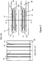
- FIG 3 shows an element of the construction for use with the current invention.
- a corrugated wettable media 40 (which may be made using similar materials and manufacturing methods to that of individual sheets 4 of the evaporative media described above) is manufactured with a vapour resistant membrane 42 adhered to one side.
- the membrane 42 may be a polymer material, although the only essential property is that it resist the flow of water vapour. It may be applied by a number of methods, including hot calendaring of plastic, adhering plastic film or the application of liquid polymers (e.g. paint), or it may be formed by treatment of the surface of the wettable media.
- the vapour membrane should be kept as thin as practicable for maximum heat transfer.
- the wettable media 40 should also be as thin as practicable consistent with its requirement to keep the surface wet and wick water to areas not directly wetted in the constructed cooler.
- the wettable media 40 from which the core elements 44 are made can be manufactured from any material which can be readily wetted. Practical materials include treated, wettable paper, moulded paper fibre slurry, wettable particulate sintered polymers and metallic or polymer films with treated or modified surfaces to promote wetting. Those skilled in the art will be aware of other wettable materials which may be used in the construction of the current invention.
- the core elements 44 may be produced using a moulding process wherein the shape of the corrugated passages may be modified to further facilitate the optimisation of airflow and heat transfer.
- the air passages through which exhaust air leaves the core may be shaped to reduce the airflow pressure losses associated with turning the air within the core from the general flow direction to a general exhaust direction.
- Figure 4 shows the component part described in Figure 3 as part of the evaporation core of an indirect evaporative cooler, as used in the evaporative heat exchanger according to the invention.
- dry, hot airflows through the dry air passage 50 where the dry air passage is contained between the vapour resistant surfaces 42 of the corrugated sheets 44.
- Adjacent wet passages 52 are formed between the wettable media surfaces 40. Airflows through the dry passages 50 in general counter flow to the wet passages 52.
- angle 54 The angle at which corrugations are set to the general direction of airflow is illustrated by the angle 54.
- This angle may be varied over a wide range to optimise the efficiency of heat transfer and resistance to airflow in the core. In general, a shallower angle 54 will result in lower airflow resistance at the penalty of reduced heat transfer efficiency.
- the angle of the corrugation 54 may be made relatively shallow, typically in the range 20 degrees to 35 degrees.
- the shallow angles of corrugation significantly reduce the airflow resistance through the core to the detriment of heat transfer efficiency. Heat transfer efficiency can be regained by extending the overall length of the core. It is found that within the range of angles stated herein, an optimised combination of reduced airflow resistance and increased core length can be achieved for each construction, consistent with adequate heat transfer efficiency.
- FIG. 5 shows the detail of construction of the components described in Figure 4 to achieve the flow patterns and directions required.
- Individual pockets 88 are constructed from two corrugated sheets with vapour resistant membranes 44. Each corrugated sheet 44 is positioned with the vapour resistant membrane 42 facing the vapour resistant membrane of the adjacent sheet. The sheets are sealed together at the top seal 84 and bottom seal 86, thus forming a complete pocket with all inner surfaces lined with a vapour resistant membrane 42.
- the top seal 84 and bottom seal 86 can be formed by methods including clinching, adhesives, plastics welding or fillers. Alternatively, if the vapour resistant membrane is formed from plastic film adhered to the wettable media 40, one of either the top seal or bottom seal can be formed by folding of a double size sheet of media and membrane combination.
- This construction results in a sealed lined pocket through which hot dry air can flow with no physical contact with the wettable media in passage 80.
- Figure 6 shows the stacking of several of the pockets 88 formed into an indirect cooler core 94.
- adjacent wettable media surfaces then form the wet passage 82.
- Air flowing through the wet passage 82 has no physical contact with the dry passage 80, but heat exchange between the wet and dry passages and evaporation within the wet passage can readily take place with the intensity promoted by the corrugated construction.
- Adjacent pockets 88 need to have the wet passages 82 separated from the dry passages 80 at the end of the core through which hot, dry air enters the core. This is achieved by sealing together adjacent pockets on the wettable media side with a seal line 90 formed by similar methods to the seals at the top and bottom of the pockets (84 and 86). With this construction, hot, dry air entering from 92 can only enter and flow through the pockets 88 lined with vapour resistant membranes 42, and must travel all the way through the pocket until it exits at the opposite end 96.
- Figure 7 shows an arrangement in accordance with a further embodiment of the present invention for wetting of the wettable media in the wet passages in a segmented manner.
- Figure 7 divides the core 94 into a number of segments 62 (shown as five segments in Figure 7 , but a lesser or greater number of segments could be used).
- Each segment has its own pumping means 60, its own water reservoir 66 and its own water distribution system 68.
- the segment 62 of core 94 with its corrugated construction tends to pass water from the water distributor 68, through the core 94 to the water reservoir 66 with little mixing of water from adjacent segments. Since, in operation, all segments are circulating water simultaneously, any tendency of the circulating water in a segment to pass through to an adjacent segment is approximately balanced by an equal and opposite tendency for water to come back from that adjacent segment. Thus, for each segment water is circulated relatively independently of each of the adjacent segments.
- the circulating water temperature in each of the segments can therefore be different, thus providing the temperature gradient necessary to thermal performance of the indirect evaporative cooler, and thus allow the delivered air temperature to approach the Dew Point.
- This arrangement for water supply to the core has several advantages over the prior art, including removal of the restriction on core height due to the wicking capability of the wettable media; water flow surplus to the requirement for evaporation flushes away any salt concentration due to evaporation and water quality can be easily monitored for salt concentration and diluted before critical concentrations are reached.
- the segmented water distribution system of Figure 7 is replaced with a single, general uniform means of distributing water over the entire core, a single water pump means, and a single water reservoir at the bottom of the core 94.
- water is applied to the core intermittently.
- the single water pump 60 is operated for a short period of time sufficient to uniformly wet all of the internal surfaces of the core, and is then turned off.
- the indirect evaporative cooler is then continued in operation, cooling by means of evaporation of the water contained on its internal surfaces.
- the wetted surfaces of the core will cool to temperatures similar to the temperatures of an indirect evaporative core wetted by means of wicking as in the prior art.
- the requirements of thermal gradient within the wetted passages are met, and thermal performance of the core is not significantly degraded.
- the wetting operation by means of the pump 60 is repeated before the wetted surfaces of the core are dried out, resulting in some degradation of thermal performance during the wetting phase.
- the core can be wetted in 30-60 seconds, and the indirect cooler operated without further wetting for 15-20 minutes without the wetted surfaces in the core drying out significantly.
- FIG 8 shows the complete core 94 with the water distribution system 68 and the airflow system 104 in place.
- Each water distributor is located within a space 101 kept separate from the water distributor space of adjacent segments by barriers 100.
- the sealed spaces 101 and barriers 100 are necessary to prevent airflow exiting from the wet passages of the core thereby causing air in the wet passages to travel all the way along the wet passages.
- a similar sealing system is necessary to separate the water reservoir 66 from adjacent water reservoirs.
- Each water reservoir 66 is sealed to the core by barriers 102 thus preventing any air from leaving the wet passages through the water reservoirs.
- the wet passage space is left open at 106.
- the opening 106 allows the now moist, warm air flowing in the wet passages to exhaust from the core 94.
- an exhaust opening 106 is provided at both the top and bottom of the core although only the top opening is shown in Figure 8 .
- the opening 106 at the bottom of the core is impracticable, satisfactory performance can still be achieved with only the opening 106 at the top with some degradation of thermal performance.
- the ratio of delivered air to exhaust air is adjusted by means of a flow restriction 108 in the delivered air stream.
- Closing flow restriction 108 increases the pressure in chamber 109 at the delivery end of the core 94, thereby increasing the flow of air back through the wet air passages.
Description
- The present invention relates to improvements in heat exchange capacity of evaporative heat exchangers. In particular, one aspect of this invention relates to a material suited to use in forming heat exchange surfaces of evaporative heat exchangers. Additional inventions are disclosed that relate to the operation of evaporative coolers. For ease of understanding, the aspects of this invention will be described in connection with the heat exchange core of counter flow evaporative coolers, as well as to methods, equipment and systems for the ventilation and cooling of enclosed spaces. The various aspects of this invention can be applied to self-contained air conditioning units suitable for supplying cooled air to an enclosed space, and to self-contained conditioning units suitable for supplying cooled water for use in heat exchange units forming part of a system for the cooling of enclosed spaces.
- Throughout this description and the claims which follow, unless the context requires otherwise, the word "comprise', or variations such as "comprises" or "comprising", will be understood to imply the inclusion of a stated integer or step or group of integers or steps.
- The reference to any prior art in this specification is not, and should not be taken as, an acknowledgement or any form of suggestion that that prior art forms part of the common general knowledge in Australia.
- The use of evaporative air coolers for the cooling of enclosed spaces is well known in the art. These coolers are typically constructed with outer walls containing a wettable, permeable media, which is kept wet with water pumped from an internal reservoir. Air from outside the building is drawn through the wetted media by means of a fan located within the evaporative cooler, and delivered either directly into the enclosed space or through a system of ducting to the enclosed space.
- As air passes through the wetted media, a phenomenon known as adiabatic saturation takes place. Moisture from the surfaces of the wetted pad evaporates into the air passing through in accordance with the humidity of the air, or its ability to take up additional water vapour. This evaporation causes an exchange of energy wherein the energy required for liquid water to evaporate to a vapour is derived from the water within the wetted pad, thereby cooling the water. The warm air entering the pad is then cooled by heat exchange to the cool water surface. The limit to which air can be cooled by this phenomenon is known as the Wet Bulb Temperature as defined in any reference work on psychrometrics.
- The air delivered by an evaporative cooler is cooled to a temperature which is always greater than the Wet Bulb Temperature, to a degree determined by the efficiency of the design of the evaporative cooler. The air delivered is also always more humid than the air entering the cooler. This limitation in achievable temperature and the addition of moisture to the air severely limits the degree of cooling available by this method, as well as limiting the use of this means of cooling to relatively hot, dry climates. In a typically hot, dry location, such as Adelaide, Australia, the design condition for evaporative cooling is 38°C Dry Bulb Temperature, 21°C Wet Bulb Temperature. Under these design conditions, a typical evaporative air cooler will deliver air at around 23.5°C, but which has been substantially humidified. This air is much less amenable to providing comfort conditions within the enclosed space than, say, a refrigeratively cooled air conditioning system, which might deliver air at 15°C, and to which no additional moisture has been added.
- There is also known, in the prior art methods, that air can be cooled to temperatures below the Wet Bulb Temperature of the incoming air while still using only the evaporation of water as the mechanism of cooling. These methods typically pre-cool the incoming air without the addition of moisture by means of dry heat exchange, prior to the air coming in contact with the moist surfaces for evaporation. The pre-cooling of air without addition of moisture reduces both the Dry Bulb and Wet Bulb temperatures of the air as can be observed on any psychrometric chart. When the air is then brought into contact with the wetted surfaces, it will be cooled to a temperature which approaches the now depressed Wet Bulb Temperature rather than the original Wet Bulb Temperature. If this process is taken to the limit, it is possible to produce cooled air which approaches the Dew Point of the incoming air, without the addition of moisture.
- This process of indirect evaporative cooling of air is well known.
SU 979796 - This configuration is further developed by Maisotsenko in
US 4,977,753 wherein the wet and dry ducts are divided into two separate sections which allows for pre-cooling of the dry airstreams prior to their entry into the wet duct thereby resulting in enhanced cooling efficiency. - A practical implementation and method of construction of the configuration of
US 4,977,753 is disclosed inUS 5,301,518 by Morozov et al. US 5,301,518 discloses a construction consisting of alternating dry ducts, which may be constructed from a variety of materials, and wet ducts constructed from capillary porous material. The airflow configuration is arranged such that the air streams in the dry and wet ducts are in counter flow as in previous disclosures. Furthermore, the configuration divides the heat exchanger into two separate stages for the purpose of achieving the requisite temperature reduction while relieving the high pressure drop inherent in the narrow air passages required for adequate heat transfer. Wetting of the porous material of the wet ducts is achieved by vertical wicking from a water reservoir beneath the heat exchanger. - The disclosure of
US 5,301,518 has been demonstrated in practical working machines, which produce air cooled to temperatures approaching the Dew Point without the addition of moisture to the air. However, the construction suffers a number of deficiencies. Resistance to air flow is high as a result of the narrow air passages needed for effective heat transfer. Heat transfer between the wet and dry air passages is inefficient due to the air boundary layers at both sides of the medium between the passages, requiring large surface areas for effective transfer of heat. The heat exchanger height is limited by the ability of the porous wet duct material to wick vertically, which in practical terms is about 200 mm. The available delivered airflow for a given size of heat exchanger is therefore low, resulting in an unacceptably large and costly construction for practical airflows. There are also considerable practical difficulties with the construction and operation of such an indirect evaporative cooler. Manifolding of air streams to the respective wet and dry ducts requires individual separation of the ducts with laborious and expensive sealing systems. When used with normal potable water supplies, water evaporated from the wet duct leaves behind salts, which cannot be easily removed, eventually clogging the heat exchanger. - It is also well known that heat exchange and wet surface evaporation rates from flat, plane surfaces can be greatly enhanced by arranging adjacent surfaces in the form of corrugations set at different angles for each adjacent sheet. This principle was disclosed by Bredberg in
US 3,262,682 and Norback inUS 3,395,903 for the construction of evaporative media for use in evaporative air coolers and cooling towers. The interaction of air streams within the adjacent corrugations in this construction of wetted media results in intense evaporation from the wet surfaces and intense heat transfer from the cold surfaces formed as a result of that evaporation. A compact, high efficiency evaporative media can be constructed with minimal pressure loss from airflow. - The intensity of evaporation and heat exchange demonstrated in corrugated evaporative media would greatly enhance the performance of an indirect evaporative cooler if applied to the airflow configuration needed for indirect cooling if such media could be readily adapted to that environment.
-
BE1013160 A6 - Another indirect evaporative heat exchanger is known from
US2004061245 A1 wherein water is supplied to the wet passages by a central wick. - The invention relates to a method of effecting heat exchange between counter current airflows in an evaporative heat exchanger, said heat exchanger including a heat exchange core comprising a plurality of alternating wet and dry passages, each passage comprising opposed corrugated surfaces, the opposed corrugated surfaces of each wet passage including a water wettable material adapted to retain water and transfer water vapour from the wettable material to air flowing along each respective wet passage; the corrugated surfaces of each dry passage being vapour resistant and cooled as water vapour transfers from the wettable material to air flowing along each adjacent wet passage, and causing a portion of the airflow exiting the dry passages to be returned to the wet passages in counter flow to the airflow in the dry passages, wherein the corrugations of the opposed corrugated surfaces are at intersecting angles, and comprising directing the counter current airflows in the wet and dry passages in a substantially horizontal direction, supplying water from above the core to the wettable material of the wet passages in a descending flow pattern and preventing water from entering and descending the dry passages.
- The invention further provides an evaporative heat exchanger adapted to operate in counter current airflow, said heat exchanger having a heat exchange core comprising a plurality of alternating wet and dry passages, each passage comprising opposed corrugated surfaces, the opposed corrugated surfaces of each wet passage including a water wettable material adapted to retain water and transfer water vapour from the wettable material to air flowing along each respective wet passage; the corrugated surfaces of each dry passage being vapour resistant and being adapted to be cooled as water vapour transfers from the wettable material to air flowing along each adjacent wet passage, and means for directing a portion of the airflow exiting the dry passages to become airflow in the wet passages, wherein said corrugations of said opposed corrugated surfaces are at intersecting angles, and wherein, in use, the counter current airflow direction is substantially horizontal in the wet and dry passages and including means for supplying water from above the core to the wettable material of the wet passages in a descending flow pattern and means for preventing water from entering and descending the dry passages.
- Preferred embodiments are subject of the dependent claims.
- The present invention will now be described by way of example with reference to the accompanying drawings, in which:
-
Figure 1 is an isometric view of the construction of a prior art corrugated evaporative media; -
Figure 2 shows schematic views of airflow paths and a water distribution method of a prior art indirect evaporative cooler; -
Figure 3 is a sectional view of a dry channel showing the construction of corrugated media for use with the claimed invention; -
Figure 4 shows a sectional view and schematic of a segment of an indirect evaporative cooler core made from the corrugated media ofFigure 3 ; -
Figure 5 is an isometric view, which shows an embodiment of the construction of a pocket segment of an indirect evaporative cooler core employing corrugated media; -
Figure 6 is an isometric view of an assembly of pocket segments ofFigure 5 when formed into an indirect evaporative cooler core; -
Figure 7 is a schematic showing the water distribution system of a further embodiment where the heat exchange core is divided into segments; and -
Figure 8 is an isometric view of an assembled indirect evaporative cooler core detailing water and airflow systems. - In
Figure 1 , the prior art corrugated media is shown as a block of sheets of corrugated, wettable media within which dry air and water on the wetted surfaces interact. Theblock 1 is constructed from individual sheets 4 of corrugated media (typically treated paper of a type which readily wicks water along its surface).Individual corrugations 6 are impressed in the media during manufacture and the sheets arranged such that the corrugations are set at anangle 8 to the edges of the block of media. Adjacent sheets 4 are typically glued together with reversed corrugation angles creating complex air and water passages within the matrix of the block. - In operation, water is introduced in the
direction 3 and applied to the top surface of the block of media. As thewater 3 descends through the matrix, it encounters numerous points within the matrix where thecorrugations 6 of adjacent sheets 4 meet. At each of these intersection points, part of the water is directed one way around the intersection, and the remainder of the water the opposite way around the intersection. Since there are numerous such intersections within the matrix, the water is quickly spread evenly throughout the block of media, thereby ensuring even wetting of the surfaces. The distribution of water within the matrix is further enhanced by the property of the media to readily wick water along its surface. Thus any deficiencies in the evenness of water distribution throughout the surfaces of the matrix are readily compensated and corrected. - Hot,
dry air 5 enters the matrix and also encounters numerous intersections of the adjacent corrugated sheets. At each intersection, the air is divided into two streams ensuring uniform movement of air throughout the matrix. At each of these intersections there is intense interaction between the air and the wetted surfaces due to the rapid and frequent changes in direction of the airflow. This intense interaction results in rapid evaporation of water from the wetted surfaces, thereby humidifying the air and cooling the waters on the wetted surfaces. Since the wetted surfaces are then considerably cooler than the hot dry incoming air, heat exchange will then occur between the air and the wetted surface, thereby cooling the air. Air leaves the matrix block as cooled, humidifiedair 7. The heat exchange during this process is also intensified due to the numerous interaction sites at the intersections of corrugations for the same reasons as for intensified evaporation espoused above. - In
Figure 2 , a prior art indirect evaporative cooler construction is shown. Hot,dry air 10 enters thedry air passage 12, proceeding past the dryair passage boundary 14. When the construction has been operating for at least a short period, the dryair passage boundary 14 will be cooler than the dry air entering thepassage 12. Heat exchange will occur and the dry air will be progressively cooled as it proceeds down the dry air passage. - The incoming hot
dry air 10 has been cooled considerably when it leaves thedry air passage 14 at 15. Aflow resistance device 28 is installed in the airflow path thereby causing an increase in air pressure at 15. This increase in pressure causes some of the now cool, dry air to turn at 26, and proceed through thewet air passage 16. The wet air passage contains a wettedmedia 18, kept moist by the wicking of water from awater reservoir 22. Since the air has not yet had any change in its moisture content, evaporation takes place from the wettedmedia 18 thereby humidifying the air and cooling the water within the wetted media by the same mechanism described above for evaporative media. As the air continues its flow down the wet passage, heat from the adjacentdry passage 12 will tend to raise the temperature of the now moistened air 26, thereby increasing its ability to evaporate moisture further. Further evaporation and heating takes place until the air 26 reaches a barrier in its path at 20, causing it to flow toexhaust 21. - Air which flows through the
flow resistance 28 becomes the deliveredair 24. This air has been cooled without the addition of moisture. In the limit of low airflows and good heat exchange, the temperature of deliveredair 24 can approach the Dew Point of the incoming air. -
Figure 3 shows an element of the construction for use with the current invention. A corrugated wettable media 40 (which may be made using similar materials and manufacturing methods to that of individual sheets 4 of the evaporative media described above) is manufactured with a vapourresistant membrane 42 adhered to one side. Themembrane 42 may be a polymer material, although the only essential property is that it resist the flow of water vapour. It may be applied by a number of methods, including hot calendaring of plastic, adhering plastic film or the application of liquid polymers (e.g. paint), or it may be formed by treatment of the surface of the wettable media. The vapour membrane should be kept as thin as practicable for maximum heat transfer. Thewettable media 40 should also be as thin as practicable consistent with its requirement to keep the surface wet and wick water to areas not directly wetted in the constructed cooler. - In the construction described above, the
wettable media 40 from which thecore elements 44 are made can be manufactured from any material which can be readily wetted. Practical materials include treated, wettable paper, moulded paper fibre slurry, wettable particulate sintered polymers and metallic or polymer films with treated or modified surfaces to promote wetting. Those skilled in the art will be aware of other wettable materials which may be used in the construction of the current invention. - Further, the
core elements 44 may be produced using a moulding process wherein the shape of the corrugated passages may be modified to further facilitate the optimisation of airflow and heat transfer. In particular, the air passages through which exhaust air leaves the core may be shaped to reduce the airflow pressure losses associated with turning the air within the core from the general flow direction to a general exhaust direction. -
Figure 4 shows the component part described inFigure 3 as part of the evaporation core of an indirect evaporative cooler, as used in the evaporative heat exchanger according to the invention. In the complete construction, dry, hot airflows through thedry air passage 50, where the dry air passage is contained between the vapourresistant surfaces 42 of thecorrugated sheets 44. Adjacentwet passages 52 are formed between the wettable media surfaces 40. Airflows through thedry passages 50 in general counter flow to thewet passages 52. - The angle at which corrugations are set to the general direction of airflow is illustrated by the
angle 54. This angle may be varied over a wide range to optimise the efficiency of heat transfer and resistance to airflow in the core. In general, ashallower angle 54 will result in lower airflow resistance at the penalty of reduced heat transfer efficiency. - The angle of the
corrugation 54 may be made relatively shallow, typically in therange 20 degrees to 35 degrees. The shallow angles of corrugation significantly reduce the airflow resistance through the core to the detriment of heat transfer efficiency. Heat transfer efficiency can be regained by extending the overall length of the core. It is found that within the range of angles stated herein, an optimised combination of reduced airflow resistance and increased core length can be achieved for each construction, consistent with adequate heat transfer efficiency. -
Figure 5 shows the detail of construction of the components described inFigure 4 to achieve the flow patterns and directions required.Individual pockets 88 are constructed from two corrugated sheets with vapourresistant membranes 44. Eachcorrugated sheet 44 is positioned with the vapourresistant membrane 42 facing the vapour resistant membrane of the adjacent sheet. The sheets are sealed together at thetop seal 84 andbottom seal 86, thus forming a complete pocket with all inner surfaces lined with a vapourresistant membrane 42. Thetop seal 84 andbottom seal 86 can be formed by methods including clinching, adhesives, plastics welding or fillers. Alternatively, if the vapour resistant membrane is formed from plastic film adhered to thewettable media 40, one of either the top seal or bottom seal can be formed by folding of a double size sheet of media and membrane combination. - This construction results in a sealed lined pocket through which hot dry air can flow with no physical contact with the wettable media in
passage 80. -
Figure 6 shows the stacking of several of thepockets 88 formed into an indirectcooler core 94. When successive pockets are placed in a stack adjacent to each other, adjacent wettable media surfaces then form thewet passage 82. Air flowing through thewet passage 82 has no physical contact with thedry passage 80, but heat exchange between the wet and dry passages and evaporation within the wet passage can readily take place with the intensity promoted by the corrugated construction. -
Adjacent pockets 88 need to have thewet passages 82 separated from thedry passages 80 at the end of the core through which hot, dry air enters the core. This is achieved by sealing together adjacent pockets on the wettable media side with aseal line 90 formed by similar methods to the seals at the top and bottom of the pockets (84 and 86). With this construction, hot, dry air entering from 92 can only enter and flow through thepockets 88 lined with vapourresistant membranes 42, and must travel all the way through the pocket until it exits at theopposite end 96. -
Figure 7 shows an arrangement in accordance with a further embodiment of the present invention for wetting of the wettable media in the wet passages in a segmented manner. - The arrangement of
Figure 7 divides the core 94 into a number of segments 62 (shown as five segments inFigure 7 , but a lesser or greater number of segments could be used). Each segment has its own pumping means 60, itsown water reservoir 66 and its ownwater distribution system 68. Thesegment 62 ofcore 94 with its corrugated construction, tends to pass water from thewater distributor 68, through the core 94 to thewater reservoir 66 with little mixing of water from adjacent segments. Since, in operation, all segments are circulating water simultaneously, any tendency of the circulating water in a segment to pass through to an adjacent segment is approximately balanced by an equal and opposite tendency for water to come back from that adjacent segment. Thus, for each segment water is circulated relatively independently of each of the adjacent segments. The circulating water temperature in each of the segments can therefore be different, thus providing the temperature gradient necessary to thermal performance of the indirect evaporative cooler, and thus allow the delivered air temperature to approach the Dew Point. This arrangement for water supply to the core has several advantages over the prior art, including removal of the restriction on core height due to the wicking capability of the wettable media; water flow surplus to the requirement for evaporation flushes away any salt concentration due to evaporation and water quality can be easily monitored for salt concentration and diluted before critical concentrations are reached. - This arrangement would approach the ideal wetting condition of wicking if there were many segments. Thermal performance is compromised if there are too few segments. In practice it has been found that dividing the core into 4-6 segments gives thermal performance approaching a wicking system with a considerably more robust and enduring core for practical applications.
- In practical examples, it has been found that water descending through the core does not remain in separated segments as in the ideal case. There is, in practice, some drift of water between the segments resulting in the accumulation of water in some segment water reservoirs, and a deficiency of water in other segments. This practical difficulty is overcome by the provision of a
bypass conduit 70 between the reservoirs, where thebypass conduit 70 is connected to each of the segment water reservoirs via anopening 72. Should the surplus/deficiency problem of water descending through the core arise, water level variations in thereservoirs 66 will equalise through theconduit 70 until a steady state of flow between the reservoirs is established. This arrangement also allows for water filling at one reservoir only, by allowing water levels to again equalise according to the steady state requirements of the individual segments. - In an alternative arrangement in accordance with a further embodiment of the present invention, the segmented water distribution system of
Figure 7 is replaced with a single, general uniform means of distributing water over the entire core, a single water pump means, and a single water reservoir at the bottom of thecore 94. In this embodiment, water is applied to the core intermittently. Thesingle water pump 60 is operated for a short period of time sufficient to uniformly wet all of the internal surfaces of the core, and is then turned off. The indirect evaporative cooler is then continued in operation, cooling by means of evaporation of the water contained on its internal surfaces. Since there is no further flow of water through the wetted surfaces of the core during this phase of operation, the wetted surfaces will cool to temperatures similar to the temperatures of an indirect evaporative core wetted by means of wicking as in the prior art. The requirements of thermal gradient within the wetted passages are met, and thermal performance of the core is not significantly degraded. The wetting operation by means of thepump 60 is repeated before the wetted surfaces of the core are dried out, resulting in some degradation of thermal performance during the wetting phase. Typically, with the selection of wettable media materials with reasonable water holding capacity, the core can be wetted in 30-60 seconds, and the indirect cooler operated without further wetting for 15-20 minutes without the wetted surfaces in the core drying out significantly. -
Figure 8 shows thecomplete core 94 with thewater distribution system 68 and theairflow system 104 in place. Each water distributor is located within aspace 101 kept separate from the water distributor space of adjacent segments bybarriers 100. The sealedspaces 101 andbarriers 100 are necessary to prevent airflow exiting from the wet passages of the core thereby causing air in the wet passages to travel all the way along the wet passages. A similar sealing system is necessary to separate thewater reservoir 66 from adjacent water reservoirs. Eachwater reservoir 66 is sealed to the core bybarriers 102 thus preventing any air from leaving the wet passages through the water reservoirs. - Immediately after the entry end of the core, the wet passage space is left open at 106. The
opening 106 allows the now moist, warm air flowing in the wet passages to exhaust from thecore 94. In the preferred embodiment, anexhaust opening 106 is provided at both the top and bottom of the core although only the top opening is shown inFigure 8 . However, if provision of theopening 106 at the bottom of the core is impracticable, satisfactory performance can still be achieved with only theopening 106 at the top with some degradation of thermal performance. - The ratio of delivered air to exhaust air is adjusted by means of a
flow restriction 108 in the delivered air stream.Closing flow restriction 108 increases the pressure inchamber 109 at the delivery end of the core 94, thereby increasing the flow of air back through the wet air passages.
Claims (9)
- A method of effecting heat exchange between counter current airflows in an evaporative heat exchanger, said heat exchanger including a heat exchange core (94) comprising a plurality of alternating wet and dry passages (52, 82; 50, 80), each passage comprising opposed corrugated surfaces (44), the opposed corrugated surfaces of each wet passage (52, 82) including a water wettable material (40) adapted to retain water and transfer water vapour from the wettable material (40) to air flowing along each respective wet passage (52, 82);the corrugated surfaces of each dry passage (50, 80) being vapour resistant and cooled as water vapour transfers from the wettable material (40) to air flowing along each adjacent wet passage (52, 82), and causing a portion of the airflow exiting the dry passages (50, 80) to be returned to the wet passages (52, 82) in counter flow to the airflow in the dry passages (50, 80), whereinthe corrugations of the opposed corrugated surfaces (44) are at intersecting angles (54), and comprising directing the counter current airflows in the wet and dry passages (52, 82; 50, 80) in a substantially horizontal direction, supplying water from above the core (94) to the wettable material (40) of the wet passages (52, 82) in a descending flow pattern and preventing water from entering and descending the dry passages (50, 80).
- A method of effecting heat exchange as claimed in claim 1, further comprising the steps of supplying water to the wet passages (52, 82) over a plurality of segments (62) from an air entry end to an air outlet end of said core (94) during operation of said heat exchanger and circulating water through each segment (62) relatively separately from adjacent segments (62) such that an appropriate temperature gradient is established from an air inlet end to an air outlet end of the core (94) by maintaining different circulating water temperatures in each segment (62).
- A method as claimed in claim 1, including supplying water to the wet passages (52, 82) in an intermittently and generally uniformly descending flow pattern across the entire core (94) and repeating application of water to the wet passages (52, 82) of the core (94) before the wettable material (40) has dried out.
- A method as claimed in claim 2 or 3, including periodic application of water flows, surplus to requirements for evaporation, to the wet passages (52, 82) for flushing away of any salt concentration in the wet passages (52, 82).
- An evaporative heat exchanger adapted to operate in counter current airflow, said heat exchanger having a heat exchange core (94) comprising a plurality of alternating wet and dry passages (52, 82; 50, 80), each passage comprising opposed corrugated surfaces, the opposed corrugated surfaces of each wet passage (52, 82) including a water wettable material (40) adapted to retain water and transfer water vapour from the wettable material (40) to air flowing along each respective wet passage (52, 82);the corrugated surfaces of each dry passage being vapour resistant and being adapted to be cooled as water vapour transfers from the wettable material (40) to air flowing along each adjacent wet passage (52, 82), and means for directing a portion of the airflow exiting the dry passages (50, 80) to become airflow in the wet passages (52, 82), wherein said corrugations of said opposed corrugated surfaces (44) are at intersecting angles, and wherein, in use, the counter current airflow direction is substantially horizontal in the wet and dry passages (52, 82; 50, 80) and including means for supplying water (60, 66, 68, 70, 72) from above the core (94) to the wettable material (40) of the wet passages (52, 82) in a descending flow pattern and means for preventing water from entering and descending the dry passages (50, 80).
- An evaporative heat exchanger as claimed in claim 5, wherein the means for supplying water (60, 66, 68, 70, 72) comprises a water distribution system including a plurality of water distributors (68) for the wet passages (52, 82), said water distributors (68) being positioned above the core (94) and disposed in spaced apart parallel relation transversely of the core (94) relative to an airflow direction through the core (94), each water distributor (68) being located within a respective space (101) above the core (94) separate from adjacent water distributor spaces (68), each water distributor (68) being supplied from a respective reservoir (66), and wherein the means for directing a portion of the airflow includes flow restriction means at an airflow exit of the dry passages (50, 80).
- An evaporative heat exchanger as claimed in claim 6, including respective pumping means (60) associated with each reservoir (66) for delivering water to each respective water distributor (68).
- An evaporative heat exchanger as claimed in claim 5, 6 or 7, wherein the water reservoirs (66) are each connected to a common water conduit (70, 72) such that water levels in the reservoirs (66) are allowed to reach an equilibrium level.
- An evaporative heat exchanger as claimed in claim 1, wherein the means for supplying water includes single pumping means (60) to periodically feed water to a water spreader above the core (94) from a reservoir.
Applications Claiming Priority (2)
| Application Number | Priority Date | Filing Date | Title |
|---|---|---|---|
| AU2005900235A AU2005900235A0 (en) | 2005-01-11 | Indirect Evaporative Cooler | |
| PCT/AU2006/000025 WO2006074508A1 (en) | 2005-01-11 | 2006-01-04 | Method and materials for improving evaporative heat exchangers |
Publications (3)
| Publication Number | Publication Date |
|---|---|
| EP1836046A1 EP1836046A1 (en) | 2007-09-26 |
| EP1836046A4 EP1836046A4 (en) | 2013-12-11 |
| EP1836046B1 true EP1836046B1 (en) | 2021-12-29 |
Family
ID=36677299
Family Applications (1)
| Application Number | Title | Priority Date | Filing Date |
|---|---|---|---|
| EP06700305.3A Active EP1836046B1 (en) | 2005-01-11 | 2006-01-04 | Method and materials for improving evaporative heat exchangers |
Country Status (12)
| Country | Link |
|---|---|
| US (2) | US20080116592A1 (en) |
| EP (1) | EP1836046B1 (en) |
| CN (1) | CN101102888B (en) |
| CA (1) | CA2594528C (en) |
| DE (1) | DE06700305T1 (en) |
| EG (1) | EG25380A (en) |
| ES (1) | ES2293873T3 (en) |
| IL (1) | IL183562A0 (en) |
| MX (2) | MX2007008386A (en) |
| TR (1) | TR200704377T1 (en) |
| WO (1) | WO2006074508A1 (en) |
| ZA (1) | ZA200711185B (en) |
Families Citing this family (23)
| Publication number | Priority date | Publication date | Assignee | Title |
|---|---|---|---|---|
| US20100319892A1 (en) * | 2008-04-02 | 2010-12-23 | United Technologies Corporation | Heat exchanging structure |
| AU2009283776A1 (en) * | 2008-08-18 | 2011-08-18 | Hmx Systems Private Limited | Direct evaporative heat exchangers, methods of manufacture thereof and applications thereof to multi-stage cooling systems |
| CA2745336A1 (en) * | 2008-11-13 | 2010-05-20 | F F Seeley Nominees Pty Ltd | Indirect evaporative cooler construction |
| US8771457B2 (en) * | 2008-12-19 | 2014-07-08 | Spx Cooling Technologies, Inc. | Fill pack assembly and method with bonded sheet pairs |
| KR101596831B1 (en) * | 2009-05-29 | 2016-03-07 | 엘지전자 주식회사 | Ventilating device and controlling method of the same |
| KR20110113880A (en) * | 2010-04-12 | 2011-10-19 | (주)엘지하우시스 | Humidification media with excellent life time and method of manufacturing the humidification media |
| US9234705B2 (en) | 2013-01-03 | 2016-01-12 | F.F. Seeley Nominees Pty Ltd | Scaleable capacity indirect evaporative cooler |
| PT3011239T (en) * | 2013-06-19 | 2021-07-30 | Seeley F F Nominees | Reduction of scale build-up in an evaporative cooling apparatus |
| EP2821744A1 (en) | 2013-07-03 | 2015-01-07 | Seeley International Pty Ltd | Improved efficiency indirect evaporative cooler |
| EP2821746A1 (en) | 2013-07-03 | 2015-01-07 | Seeley International Pty Ltd | Indirect evaporative cooler system with scaleable capacity |
| US20150048528A1 (en) * | 2013-08-19 | 2015-02-19 | Sean Anderson Barton | Fill material for direct-contact heat/mass exchangers |
| CN104165540A (en) * | 2014-07-31 | 2014-11-26 | 中化工程沧州冷却技术有限公司 | Open circulating water, gas and liquid orthogonal diaphragm plate type air cooler |
| AU2015316185B2 (en) * | 2014-09-08 | 2021-02-04 | Ff Seeley Nominees Pty Ltd | Compact indirect evaporative cooler |
| RU2697299C2 (en) * | 2014-12-23 | 2019-08-13 | Эвапко, Инк. | Bidirectional filler for use in cooling towers |
| CN104534604B (en) * | 2015-01-23 | 2017-05-31 | 天津大学 | The board-like dew point indirect evaporative cooler of adverse current and channel partition of external flow dividing structure |
| CN106767051B (en) * | 2017-01-14 | 2022-06-10 | 陈祖卫 | Indirect evaporation heat exchanger and cooling tower thereof |
| IT201700073781A1 (en) * | 2017-06-30 | 2018-12-30 | Impresind S R L | ADIABATIC COOLING PLANT WITH PHOTOCATALYTIC PROPERTIES FOR AIR PURIFICATION |
| CN109137145A (en) * | 2018-07-16 | 2019-01-04 | 绍兴百慧科技有限公司 | A kind of solvent recovery unit of solution electrostatic spinning |
| US11686538B2 (en) * | 2018-09-25 | 2023-06-27 | Brentwood Industries, Inc. | Cross corrugated media and related method |
| CN112577140A (en) * | 2020-12-14 | 2021-03-30 | 昆山亚冠过滤技术研究院有限公司 | Suspended ceiling type full-house humidifier |
| IT202100023189A1 (en) * | 2021-09-08 | 2023-03-08 | Gigola & Riccardi S P A | Evaporative panels with shaped edges for coupling with adjacent panels or with respective support structures. |
| WO2023099945A1 (en) * | 2021-12-02 | 2023-06-08 | Freshape Sa | Multi-stage adsorber device and uses thereof for chilling and/or atmospheric water harvesting |
| US11920823B2 (en) | 2022-01-26 | 2024-03-05 | Hog Slat, Inc. | Automated evaporative system flush |
Family Cites Families (42)
| Publication number | Priority date | Publication date | Assignee | Title |
|---|---|---|---|---|
| SE307963B (en) * | 1962-06-27 | 1969-01-27 | Munters C | |
| SE318587B (en) * | 1964-07-10 | 1969-12-15 | C Munters | |
| US3542636A (en) * | 1965-07-28 | 1970-11-24 | Kurt Wandel | Corrugated board |
| SE311371B (en) * | 1966-01-26 | 1969-06-09 | Munters C | |
| SE315380C (en) * | 1967-02-06 | 1975-04-03 | Fagerstataket Ab | |
| US3664095A (en) * | 1968-10-21 | 1972-05-23 | Gunnar C F Asker | Exchange packing element |
| US3659623A (en) * | 1969-12-02 | 1972-05-02 | Baltimore Aircoil Co Inc | Water supply system |
| GB1376308A (en) * | 1971-06-04 | 1974-12-04 | Cooling Dev Ltd | Art of evaporative cooling |
| SE391392B (en) * | 1974-02-22 | 1977-02-14 | Munters Ab Carl | CONNECTOR FOR AIR AND WATER |
| SE7508256L (en) * | 1975-07-18 | 1977-01-19 | Munters Ab Carl | WAY TO PRODUCE A HEAT EXCHANGER BODY FOR RECOVERY EXCHANGERS |
| SU979796A1 (en) | 1976-08-17 | 1982-12-07 | Одесский Инженерно-Строительный Институт | Unit for indirect evaporation cooling of air |
| SE7809801L (en) * | 1978-09-14 | 1980-03-15 | Lagerquist Roy | EVAPORATION CONDENSATION PROCEDURE FOR HEATING SYSTEMS |
| US4544513A (en) * | 1983-04-15 | 1985-10-01 | Arvin Industries, Inc. | Combination direct and indirect evaporative media |
| SE8400302L (en) * | 1984-01-20 | 1985-08-18 | Munters Ab Carl | Contact body |
| US4610902A (en) * | 1985-09-10 | 1986-09-09 | Manville Service Corporation | Roofing membranes and system |
| RU1778453C (en) * | 1987-05-12 | 1992-11-30 | Одесский Инженерно-Строительный Институт | Method of processing air in room |
| DE8904345U1 (en) * | 1989-04-07 | 1989-05-18 | Streng, Andreas, Dipl.-Ing., 5210 Troisdorf, De | |
| DE3918483A1 (en) * | 1989-06-06 | 1990-12-13 | Munters Euroform Gmbh Carl | FILLED BODY |
| US5212956A (en) * | 1991-01-18 | 1993-05-25 | Ari-Tec Marketing, Inc. | Method and apparatus for gas cooling |
| US5315843A (en) * | 1992-08-13 | 1994-05-31 | Acma Limited | Evaporative air conditioner unit |
| CN2146686Y (en) * | 1993-01-01 | 1993-11-17 | 余宗宁 | Condenser for injection pump system |
| DE19518270C1 (en) * | 1995-05-18 | 1996-08-22 | Fraunhofer Ges Forschung | Non-slip polished floor covering |
| IL125927A0 (en) * | 1998-08-25 | 1999-04-11 | Agam Energy Systems Ltd | An evaporative media and a cooling tower utilizing same |
| US6186223B1 (en) * | 1998-08-27 | 2001-02-13 | Zeks Air Drier Corporation | Corrugated folded plate heat exchanger |
| US20020136885A1 (en) * | 1999-10-22 | 2002-09-26 | Yaeger Ronald J. | Contact media for evaporative cooler |
| BE1013160A6 (en) * | 1999-11-30 | 2001-10-02 | Offringa Dirk Dooitze | Working method and device for cooling air |
| DE10001694A1 (en) * | 2000-01-18 | 2001-07-19 | Montz Gmbh Julius | Packing for heat- and mass exchange columns includes ridges making defined angles at their extremities, with top and bottom, horizontal panel edges |
| AU2001234938A1 (en) * | 2000-02-07 | 2001-08-14 | Idalex Technologies, Inc. | Method and apparatus for dew point evaporative product cooling |
| US6776001B2 (en) * | 2000-02-07 | 2004-08-17 | Idalex Technologies, Inc. | Method and apparatus for dew point evaporative product cooling |
| ES2312416T3 (en) * | 2000-02-23 | 2009-03-01 | Schlom, Leslie | A COOLING AND PRE-COOLING HEAT EXCHANGER FOR THE CONDITIONING OF THE ADMISSION AIR OF A TURBINE. |
| US6497107B2 (en) * | 2000-07-27 | 2002-12-24 | Idalex Technologies, Inc. | Method and apparatus of indirect-evaporation cooling |
| WO2002027254A2 (en) * | 2000-09-27 | 2002-04-04 | Idalex Technologies, Inc. | Method and plate apparatus for dew point evaporative cooler |
| KR100409265B1 (en) * | 2001-01-17 | 2003-12-18 | 한국과학기술연구원 | Regenerative evaporative cooler |
| US6533253B1 (en) * | 2001-03-29 | 2003-03-18 | General Shelters Of Texas, S.B. Ltd. | Light attenuating evaporative cooling pad |
| JP4634659B2 (en) | 2001-07-05 | 2011-02-16 | 東罐興業株式会社 | Corrugated sheet and packaging box using the same |
| US6854278B2 (en) * | 2001-08-20 | 2005-02-15 | Valeriy Maisotsenko | Method of evaporative cooling of a fluid and apparatus therefor |
| RU2320947C2 (en) * | 2001-12-12 | 2008-03-27 | Айдалекс Текнолоджиз, Инк. | Method of evaporative cooling to dew point and device for evaporative cooler |
| US20040061245A1 (en) * | 2002-08-05 | 2004-04-01 | Valeriy Maisotsenko | Indirect evaporative cooling mechanism |
| NL1022794C2 (en) * | 2002-10-31 | 2004-09-06 | Oxycell Holding Bv | Method for manufacturing a heat exchanger, as well as heat exchanger obtained with the method. |
| NL1023471C2 (en) * | 2003-01-23 | 2004-07-26 | Oxycell Holding Bv | Dew point cooler with antimicrobial features. |
| US7093452B2 (en) * | 2004-03-24 | 2006-08-22 | Acma Limited | Air conditioner |
| US20060292349A1 (en) * | 2005-05-05 | 2006-12-28 | Seeley Frederic F | An evaporative material system and method of manufacture |
-
2006
- 2006-01-04 CN CN2006800021209A patent/CN101102888B/en not_active Expired - Fee Related
- 2006-01-04 TR TR2007/04377T patent/TR200704377T1/en unknown
- 2006-01-04 US US11/792,500 patent/US20080116592A1/en not_active Abandoned
- 2006-01-04 EP EP06700305.3A patent/EP1836046B1/en active Active
- 2006-01-04 CA CA2594528A patent/CA2594528C/en active Active
- 2006-01-04 MX MX2007008386A patent/MX2007008386A/en unknown
- 2006-01-04 MX MX2010014008A patent/MX345482B/en unknown
- 2006-01-04 DE DE06700305T patent/DE06700305T1/en active Pending
- 2006-01-04 ES ES06700305T patent/ES2293873T3/en active Active
- 2006-01-04 WO PCT/AU2006/000025 patent/WO2006074508A1/en active Application Filing
-
2007
- 2007-05-30 IL IL183562A patent/IL183562A0/en active IP Right Grant
- 2007-05-31 ZA ZA200711185A patent/ZA200711185B/en unknown
- 2007-07-08 EG EGNA2007000702 patent/EG25380A/en active
-
2011
- 2011-04-08 US US13/082,993 patent/US8636269B2/en active Active
Also Published As
| Publication number | Publication date |
|---|---|
| WO2006074508A1 (en) | 2006-07-20 |
| US20110220333A1 (en) | 2011-09-15 |
| EP1836046A4 (en) | 2013-12-11 |
| CN101102888A (en) | 2008-01-09 |
| DE06700305T1 (en) | 2008-05-21 |
| EG25380A (en) | 2011-12-22 |
| CN101102888B (en) | 2011-01-19 |
| US8636269B2 (en) | 2014-01-28 |
| CA2594528A1 (en) | 2006-07-20 |
| US20080116592A1 (en) | 2008-05-22 |
| MX2007008386A (en) | 2007-11-08 |
| CA2594528C (en) | 2014-06-17 |
| ZA200711185B (en) | 2008-10-29 |
| ES2293873T1 (en) | 2008-04-01 |
| IL183562A0 (en) | 2007-09-20 |
| TR200704377T1 (en) | 2007-08-21 |
| MX345482B (en) | 2017-01-18 |
| EP1836046A1 (en) | 2007-09-26 |
| ES2293873T3 (en) | 2022-04-07 |
Similar Documents
| Publication | Publication Date | Title |
|---|---|---|
| EP1836046B1 (en) | Method and materials for improving evaporative heat exchangers | |
| US7197887B2 (en) | Method and plate apparatus for dew point evaporative cooler | |
| US9140471B2 (en) | Indirect evaporative coolers with enhanced heat transfer | |
| US6854278B2 (en) | Method of evaporative cooling of a fluid and apparatus therefor | |
| EP1334325B1 (en) | Method and plate apparatus for dew point evaporative cooler | |
| FI57478B (en) | SAETT FOER KYLNING AV LUFT | |
| KR101497297B1 (en) | Evaporative cooling device | |
| US20130340449A1 (en) | Indirect evaporative cooler using membrane-contained liquid desiccant for dehumidification and flocked surfaces to provide coolant flow | |
| US6776001B2 (en) | Method and apparatus for dew point evaporative product cooling | |
| CN104081148B (en) | Heat exchange matrix | |
| US5718848A (en) | Intensification of evaporation and heat transfer | |
| RU2320947C2 (en) | Method of evaporative cooling to dew point and device for evaporative cooler | |
| EP3473315A1 (en) | Evaporative media pad with reduced internal spacing | |
| WO2001057459A9 (en) | Method and apparatus for dew point evaporative product cooling | |
| AU2006206035B2 (en) | Method and materials for improving evaporative heat exchangers | |
| AU696886B2 (en) | Intensification of evaporation and heat transfer | |
| MXPA96001441A (en) | Intensification of evaporation and deca transfer |
Legal Events
| Date | Code | Title | Description |
|---|---|---|---|
| PUAI | Public reference made under article 153(3) epc to a published international application that has entered the european phase |
Free format text: ORIGINAL CODE: 0009012 |
|
| 17P | Request for examination filed |
Effective date: 20070706 |
|
| AK | Designated contracting states |
Kind code of ref document: A1 Designated state(s): DE ES FR GR IT |
|
| REG | Reference to a national code |
Ref country code: GR Ref legal event code: PP Ref document number: 20070300017 Country of ref document: GR |
|
| EL | Fr: translation of claims filed | ||
| DAX | Request for extension of the european patent (deleted) | ||
| RBV | Designated contracting states (corrected) |
Designated state(s): DE ES FR GR IT |
|
| DET | De: translation of patent claims | ||
| A4 | Supplementary search report drawn up and despatched |
Effective date: 20131111 |
|
| RIC1 | Information provided on ipc code assigned before grant |
Ipc: F28F 25/00 20060101ALI20131105BHEP Ipc: B32B 3/28 20060101AFI20131105BHEP Ipc: F28D 5/02 20060101ALI20131105BHEP Ipc: B32B 29/08 20060101ALN20131105BHEP Ipc: F24F 6/00 20060101ALI20131105BHEP Ipc: B32B 25/10 20060101ALN20131105BHEP Ipc: F28F 25/08 20060101ALN20131105BHEP Ipc: B32B 29/06 20060101ALN20131105BHEP |
|
| STAA | Information on the status of an ep patent application or granted ep patent |
Free format text: STATUS: EXAMINATION IS IN PROGRESS |
|
| 17Q | First examination report despatched |
Effective date: 20161222 |
|
| STAA | Information on the status of an ep patent application or granted ep patent |
Free format text: STATUS: EXAMINATION IS IN PROGRESS |
|
| GRAP | Despatch of communication of intention to grant a patent |
Free format text: ORIGINAL CODE: EPIDOSNIGR1 |
|
| STAA | Information on the status of an ep patent application or granted ep patent |
Free format text: STATUS: GRANT OF PATENT IS INTENDED |
|
| INTG | Intention to grant announced |
Effective date: 20210617 |
|
| RIC1 | Information provided on ipc code assigned before grant |
Ipc: B32B 3/28 20060101AFI20210604BHEP Ipc: F24F 6/00 20060101ALI20210604BHEP Ipc: F28F 25/00 20060101ALI20210604BHEP Ipc: F28D 5/02 20060101ALI20210604BHEP Ipc: F24F 1/0007 20190101ALI20210604BHEP Ipc: F24F 5/00 20060101ALI20210604BHEP Ipc: B32B 25/10 20060101ALN20210604BHEP Ipc: B32B 29/08 20060101ALN20210604BHEP Ipc: F28F 25/08 20060101ALN20210604BHEP Ipc: B32B 29/06 20060101ALN20210604BHEP |
|
| GRAS | Grant fee paid |
Free format text: ORIGINAL CODE: EPIDOSNIGR3 |
|
| GRAA | (expected) grant |
Free format text: ORIGINAL CODE: 0009210 |
|
| STAA | Information on the status of an ep patent application or granted ep patent |
Free format text: STATUS: THE PATENT HAS BEEN GRANTED |
|
| REG | Reference to a national code |
Ref country code: DE Ref legal event code: R081 Ref document number: 602006060265 Country of ref document: DE Owner name: SEELEY INTERNATIONAL PTY LTD, AU Free format text: FORMER OWNER: F.F. SEELEY NOMINEES PTY. LTD., ST. MARY'S, AU |
|
| RAP1 | Party data changed (applicant data changed or rights of an application transferred) |
Owner name: SEELEY INTERNATIONAL PTY LTD |
|
| AK | Designated contracting states |
Kind code of ref document: B1 Designated state(s): DE ES FR GR IT |
|
| REG | Reference to a national code |
Ref country code: DE Ref legal event code: R096 Ref document number: 602006060265 Country of ref document: DE |
|
| REG | Reference to a national code |
Ref country code: ES Ref legal event code: FG2A Ref document number: 2293873 Country of ref document: ES Kind code of ref document: T3 Effective date: 20220407 |
|
| PG25 | Lapsed in a contracting state [announced via postgrant information from national office to epo] |
Ref country code: GR Free format text: LAPSE BECAUSE OF FAILURE TO SUBMIT A TRANSLATION OF THE DESCRIPTION OR TO PAY THE FEE WITHIN THE PRESCRIBED TIME-LIMIT Effective date: 20220330 |
|
| REG | Reference to a national code |
Ref country code: DE Ref legal event code: R097 Ref document number: 602006060265 Country of ref document: DE |
|
| PLBE | No opposition filed within time limit |
Free format text: ORIGINAL CODE: 0009261 |
|
| STAA | Information on the status of an ep patent application or granted ep patent |
Free format text: STATUS: NO OPPOSITION FILED WITHIN TIME LIMIT |
|
| 26N | No opposition filed |
Effective date: 20220930 |
|
| PGFP | Annual fee paid to national office [announced via postgrant information from national office to epo] |
Ref country code: ES Payment date: 20230224 Year of fee payment: 18 |
|
| PGFP | Annual fee paid to national office [announced via postgrant information from national office to epo] |
Ref country code: IT Payment date: 20230102 Year of fee payment: 18 Ref country code: DE Payment date: 20230131 Year of fee payment: 18 |
|
| PGFP | Annual fee paid to national office [announced via postgrant information from national office to epo] |
Ref country code: FR Payment date: 20231101 Year of fee payment: 19 |