EP1835463A2 - Vorrichtung und Verfahren zur Erkennung von Hindernissen - Google Patents
Vorrichtung und Verfahren zur Erkennung von Hindernissen Download PDFInfo
- Publication number
- EP1835463A2 EP1835463A2 EP07250949A EP07250949A EP1835463A2 EP 1835463 A2 EP1835463 A2 EP 1835463A2 EP 07250949 A EP07250949 A EP 07250949A EP 07250949 A EP07250949 A EP 07250949A EP 1835463 A2 EP1835463 A2 EP 1835463A2
- Authority
- EP
- European Patent Office
- Prior art keywords
- hypothesis
- obstacle
- state
- measurement
- group
- Prior art date
- Legal status (The legal status is an assumption and is not a legal conclusion. Google has not performed a legal analysis and makes no representation as to the accuracy of the status listed.)
- Withdrawn
Links
Images


Classifications
-
- G—PHYSICS
- G06—COMPUTING OR CALCULATING; COUNTING
- G06T—IMAGE DATA PROCESSING OR GENERATION, IN GENERAL
- G06T7/00—Image analysis
- G06T7/20—Analysis of motion
-
- G—PHYSICS
- G06—COMPUTING OR CALCULATING; COUNTING
- G06V—IMAGE OR VIDEO RECOGNITION OR UNDERSTANDING
- G06V10/00—Arrangements for image or video recognition or understanding
- G06V10/20—Image preprocessing
- G06V10/24—Aligning, centring, orientation detection or correction of the image
-
- G—PHYSICS
- G06—COMPUTING OR CALCULATING; COUNTING
- G06V—IMAGE OR VIDEO RECOGNITION OR UNDERSTANDING
- G06V20/00—Scenes; Scene-specific elements
- G06V20/50—Context or environment of the image
- G06V20/56—Context or environment of the image exterior to a vehicle by using sensors mounted on the vehicle
- G06V20/58—Recognition of moving objects or obstacles, e.g. vehicles or pedestrians; Recognition of traffic objects, e.g. traffic signs, traffic lights or roads
Definitions
- the present invention relates to an obstacle tracking apparatus for detecting and tracking an obstacle such as a vehicle using an image which can be acquired from a TV camera mounted to a moving object represented by a vehicle such as a motor vehicle and a method thereof.
- an obstacle tracking apparatus including: an image acquiring unit mounted to a moving object and configured to acquire image sequences including an obstacle; an obstacle detecting unit configured to detect candidate areas of the obstacle at the current time from the image sequences; a state hypothesis storing unit configured to store a state hypothesis group including one or a plurality of state hypothesis or hypotheses of the obstacle at a previous time, the each state hypothesis relating to a motion of the obstacle; a measurement hypothesis generating unit configured to generate a measurement hypothesis group including one or a plurality of the measurement hypothesis or hypotheses obtained by combining measurement hypotheses for the respective positions of the candidate areas of the obstacle and an measurement hypothesis in case the obstacle is not detected; a likelihood calculating unit configured to calculate likelihoods of respective combinations of the respective state hypotheses included in the state hypothesis group and the respective measurement hypotheses included in the measurement hypothesis group; a state hypothesis updating unit configured to obtain a highest likelihood from the likelihoods of the respective combinations of the respective state hypotheses included in the state hypothesis group and the respective measurement hypo
- the position of the obstacle can be detected and tracked stably from the image sequences acquired by the image input unit mounted to the vehicle.
- a plurality of state hypotheses are set using a plurality of measured positions for a detected obstacle considering ambiguity of obstacle tracking, and select the state hypothesis whose likelihood is the highest among the state hypothesis group at the current time as a state of the obstacle.
- Fig. 1 is a flowchart which also serves as a block diagram of an obstacle tracking apparatus in this embodiment.
- the obstacle tracking apparatus includes an image input unit 1, an obstacle detecting unit 2, a measured position setting unit 3, a hypothesis generating unit 4, a likelihood calculating unit 5, the hypothesis selecting unit 6, and a reliability evaluating unit 7.
- the obstacle tracking apparatus can be realized by using, for example, a multi-purpose computer apparatus as a basic hardware.
- the obstacle detecting unit 2, the measureed position setting unit 3, the hypothesis generating unit 4, the likelihood calculating unit 5, the hypothesis selecting unit 6 and the reliability evaluating unit 7 can be realized by causing a processor mounted to the computer to execute a program.
- the image input unit 1 has stereo TV cameras that can acquire images of a front area of a vehicle to which the stereo TV cameras is mounted.
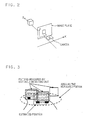
- Fig. 2 shows a coordinate system in this embodiment, in which X represents the horizontal direction, Z represents the depth direction of a world coordinate system, and x represents the horizontal direction and y represents the vertical direction of an image coordinate system.
- the time t is equal the number of frames of the image sequences.
- the obstacle detecting unit 2 determines candidate areas of the obstacle from the image sequences acquired by the image input unit 1.
- the obstacle detecting unit 2 detects the candidate areas of the obstacle of the vehicle or the like using images of stereo cameras. At this time, as shown in Fig. 2, the position in the image coordinate system (x, y) and the position in the world coordinate system (X, Z) is obtained from a disparity between the image of the left camera and the right camera.
- Stereo image recognition system for drive assist there is a method described in " Stereo image recognition system for drive assist” IEICE, PRMU97-30, 1997, pp39-46 .
- the measured position setting unit 3 sets the measured position of the obstacle at a current time t.
- the setting method is as follows.
- an estimated position of an obstacle that is currently tracked at a previous time t-1 is calculated from the hypothesis generating unit 4.
- This estimated position is the estimated position at the previous time t-1 obtained according to the same method of obtaining an estimated position at the current time t, which will be described later.
- the obtained estimated position and a detected position at a current time t obtained by the obstacle detecting unit 2 are compared, and when the distance between the estimated position and the detected position is equal to or smaller than a threshold value, the detected position is determined as a "measured position".
- the number of the measured position may not be only one, and all the detected positions which have the distance described above equal to or smaller than the threshold value are recognized as the measured positions. For example, in the expression 1 shown below, M-units of measured positions exist.
- the measured position is represented by a distance Z in the depth direction and a distance X in the horizontal direction. However, the measured position is only represented by the distance Z in the depth direction in the following description.
- Reference sign Zm designates a measured position and ⁇ R designates a standard deviation of the measurement distribution.
- the measured position obtained by various detecting methods can also be handled.
- the hypothesis generating unit 4 generates measurement hypotheses for the M-units of measured positions set by the measured position setting unit 3 for the respective obstacles.
- the 0th measurement hypothesis is a hypothesis that there is no measured position.
- the hypothesis generating unit 4 holds N-units of state hypotheses, that is, a state hypothesis group described later.
- state in this description represents kinetic information of the obstacle such as the position or the speed of the obstacle, and the term “state hypothesis” represents a hypothesis relating to these states.
- state hypothesis group will be described further in detail.
- x t represents a state vector
- P t represents a covariance matrix of the state vector
- Z t represents a distance
- R represents an error covariance matrix (standard deviation ⁇ R ) of the measured position in a state space at the time of.
- Reference sign A represents a state transition matrix
- Q represents a process noise. Since linear motion of acceleration model is assumed, the following expression is established.
- vector x represents the position or the speed of the obstacle in the world coordinate system
- subscripts of x and ⁇ represent the time
- superscripts also represent the number of the state hypothesis.
- Likelihood means the extent of reliability, and the higher the likelihood is, the higher the reliability becomes.
- the likelihood calculating unit 5 updates the state hypothesis group held in the hypothesis generating unit 4 through steps of prediction, measurement and estimation described below, and then calculates the likelihood.
- P 0 (i) represents a component of a first raw and a first column of P t -(i) .
- ⁇ vector x t/t-1 > represents a predicted position in the current state
- ⁇ vector x t-1/t-1 > represents the estimated position in the past state
- P t/t-1 represents the error-covariance matrix in the predicted state
- P t-1/t-1 represents a error-covariance matrix in the past state.
- a posterior probability is calculated as a product of the prior probability and the measurement probability using Expression 8 by Bayes rule.
- the posterior probability is set to the likelihood of the new state hypothesis.
- the posterior probability is calculated by Expression 9 with a weighting coefficient w of the combination of the measurement hypothesis and the state hypothesis.
- the weighting coefficient w of the combination of the measurement hypothesis and the state hypothesis is using when additional information exists.
- the hypothesis selecting unit 6 selects combinations whereby a highest likelihood is achieved for each of M-units of measurement hypotheses from a new state hypothesis with Expression 10.
- Expression 10 ⁇ t j max ⁇ t i ⁇ j
- ⁇ t (j) is normalized so that the total of the likelihoods in all the state hypotheses becomes "1".
- the one whereby the value of ⁇ t (j) is maximum is selected as the state hypothesis of the obstacle at the current time t.
- the reliability evaluating unit 7 acquires the kinetic information such as the position, speed and acceleration of the obstacle from the state hypothesis selected by the hypothesis selecting unit 6.
- the reliability is evaluated from an extent of error of a kinetic state, and tracking of the obstacle whose reliability is low is stopped.
- the process as described above is performed for the image sequences, and the obstacle such as the vehicle is tracked to detect the accurate position thereof.
- the likelihoods of the combination of the state hypothesis and the measurement hypothesis from the time t-2 to the time t-1 is calculated. -Then, the likelihood of the 2nd state hypothesis and the 0th measurement hypothesis is the maximum, and the 0th state hypothesis on the basis of the 0th measurement hypothesis which means that the measured position does not exist in the state at the time t-1 is selected.
- the likelihood of the combination of the state hypothesis and the measurement hypothesis from the time t-1 to the time t is calculated. Then, the likelihood of the combination of the 0th state hypothesis and the 2nd measurement hypothesis become is the maximum, and the 2nd state hypothesis on the basis of the 2nd measurement hypothesis as the result of the stereo vision is selected.
- the apparatus tracks obstacles using multi hypotheses and can detect the position ob the obstacle by selecting the state hypothesis whose likelihood is the highest. Accordingly, a phenomenon of erroneous tracking of another obstacle when the candidate areas of the obstacle are not detected is reduced, and even when erroneous tracking occurs temporarily, the correct obstacle can be tracked again. In addition, since the hypothesis is generated adequately according to the detected candidate areas of the obstacle, the processing time can be reduced.
- the obstacle detecting unit 2 can detect the obstacle by an active sensor such as an extremely high frequency wave radar (MMW).
- MMW extremely high frequency wave radar
Landscapes
- Engineering & Computer Science (AREA)
- Physics & Mathematics (AREA)
- General Physics & Mathematics (AREA)
- Multimedia (AREA)
- Theoretical Computer Science (AREA)
- Computer Vision & Pattern Recognition (AREA)
- Image Analysis (AREA)
- Radar Systems Or Details Thereof (AREA)
- Length Measuring Devices By Optical Means (AREA)
- Image Processing (AREA)
- Closed-Circuit Television Systems (AREA)
- Traffic Control Systems (AREA)
Applications Claiming Priority (1)
| Application Number | Priority Date | Filing Date | Title |
|---|---|---|---|
| JP2006068402A JP2007249309A (ja) | 2006-03-13 | 2006-03-13 | 障害物追跡装置及びその方法 |
Publications (1)
| Publication Number | Publication Date |
|---|---|
| EP1835463A2 true EP1835463A2 (de) | 2007-09-19 |
Family
ID=38226511
Family Applications (1)
| Application Number | Title | Priority Date | Filing Date |
|---|---|---|---|
| EP07250949A Withdrawn EP1835463A2 (de) | 2006-03-13 | 2007-03-07 | Vorrichtung und Verfahren zur Erkennung von Hindernissen |
Country Status (4)
| Country | Link |
|---|---|
| US (1) | US20070211917A1 (de) |
| EP (1) | EP1835463A2 (de) |
| JP (1) | JP2007249309A (de) |
| CN (1) | CN101038164A (de) |
Families Citing this family (18)
| Publication number | Priority date | Publication date | Assignee | Title |
|---|---|---|---|---|
| US7639841B2 (en) * | 2004-12-20 | 2009-12-29 | Siemens Corporation | System and method for on-road detection of a vehicle using knowledge fusion |
| JP5075672B2 (ja) * | 2008-02-25 | 2012-11-21 | 株式会社東芝 | 対象物検出装置及び方法 |
| JP5180733B2 (ja) * | 2008-08-19 | 2013-04-10 | セコム株式会社 | 移動物体追跡装置 |
| CN101408978B (zh) * | 2008-11-27 | 2010-12-01 | 东软集团股份有限公司 | 一种基于单目视觉的障碍物检测方法及装置 |
| CN101436300B (zh) * | 2008-12-10 | 2012-10-31 | 东软集团股份有限公司 | 障碍物分割方法及装置 |
| US8364630B1 (en) * | 2009-11-02 | 2013-01-29 | The Boeing Company | System and method for controlling network centric operation with Bayesian probability models of complex hypothesis spaces |
| WO2011101945A1 (ja) | 2010-02-19 | 2011-08-25 | パナソニック株式会社 | 物体位置補正装置、物体位置補正方法、及び物体位置補正プログラム |
| JP5620147B2 (ja) * | 2010-05-24 | 2014-11-05 | 株式会社豊田中央研究所 | 可動物予測装置及びプログラム |
| US8818702B2 (en) * | 2010-11-09 | 2014-08-26 | GM Global Technology Operations LLC | System and method for tracking objects |
| US8654005B2 (en) * | 2011-10-14 | 2014-02-18 | Raytheon Company | Methods for resolving radar ambiguities using multiple hypothesis tracking |
| CN104424648B (zh) * | 2013-08-20 | 2018-07-24 | 株式会社理光 | 对象跟踪方法和设备 |
| JP2015184929A (ja) * | 2014-03-24 | 2015-10-22 | 株式会社東芝 | 立体物検出装置、立体物検出方法、および立体物検出プログラム |
| CN103914688B (zh) * | 2014-03-27 | 2018-02-02 | 北京科技大学 | 一种城市道路障碍物识别系统 |
| CN109509210B (zh) * | 2017-09-15 | 2020-11-24 | 百度在线网络技术(北京)有限公司 | 障碍物跟踪方法和装置 |
| CN112272778A (zh) * | 2018-06-13 | 2021-01-26 | 三菱电机株式会社 | 轨迹推测装置以及便携信息终端 |
| JP7115376B2 (ja) * | 2019-03-18 | 2022-08-09 | 日本電信電話株式会社 | 回転状態推定装置、方法及びプログラム |
| WO2020258187A1 (zh) * | 2019-06-27 | 2020-12-30 | 深圳市大疆创新科技有限公司 | 一种状态检测方法、装置及可移动平台 |
| US12614290B2 (en) * | 2020-10-28 | 2026-04-28 | Kyocera Corporation | Object tracking device and object tracking method |
Family Cites Families (4)
| Publication number | Priority date | Publication date | Assignee | Title |
|---|---|---|---|---|
| JP3461980B2 (ja) * | 1995-08-25 | 2003-10-27 | 株式会社東芝 | 高速描画方法および装置 |
| US5959672A (en) * | 1995-09-29 | 1999-09-28 | Nippondenso Co., Ltd. | Picture signal encoding system, picture signal decoding system and picture recognition system |
| US7130446B2 (en) * | 2001-12-03 | 2006-10-31 | Microsoft Corporation | Automatic detection and tracking of multiple individuals using multiple cues |
| US6999599B2 (en) * | 2002-06-07 | 2006-02-14 | Microsoft Corporation | System and method for mode-based multi-hypothesis tracking using parametric contours |
-
2006
- 2006-03-13 JP JP2006068402A patent/JP2007249309A/ja not_active Abandoned
- 2006-11-14 US US11/598,734 patent/US20070211917A1/en not_active Abandoned
-
2007
- 2007-03-07 EP EP07250949A patent/EP1835463A2/de not_active Withdrawn
- 2007-03-13 CN CNA200710086335XA patent/CN101038164A/zh active Pending
Also Published As
| Publication number | Publication date |
|---|---|
| US20070211917A1 (en) | 2007-09-13 |
| JP2007249309A (ja) | 2007-09-27 |
| CN101038164A (zh) | 2007-09-19 |
Similar Documents
| Publication | Publication Date | Title |
|---|---|---|
| EP1835463A2 (de) | Vorrichtung und Verfahren zur Erkennung von Hindernissen | |
| US10672131B2 (en) | Control method, non-transitory computer-readable storage medium, and control apparatus | |
| Zhou et al. | A robust lane detection and tracking method based on computer vision | |
| EP3193306B1 (de) | Verfahren und vorrichtung zum schätzen einer ausrichtung einer kamera in bezug auf eine fahrbahn | |
| Reuter et al. | The multiple model labeled multi-Bernoulli filter | |
| CN103927764B (zh) | 一种结合目标信息和运动估计的车辆跟踪方法 | |
| EP3683768A1 (de) | Verfahren und system zum initialisieren von vorlagen von objekten in bewegung | |
| Granström et al. | On the use of multiple measurement models for extended target tracking | |
| JP2010244549A (ja) | ロボットの少なくとも1つの将来的活動を決定する決定メカニズム、方法、モジュールおよび決定するように構成されたロボット | |
| CN111007880B (zh) | 一种基于汽车雷达的扩展目标跟踪方法 | |
| KR101885839B1 (ko) | 객체추적을 위한 특징점 선별 장치 및 방법 | |
| US20190043168A1 (en) | An image processing device, an image processing method, and computer-readable recording medium | |
| CN105574892A (zh) | 雷达图像中的基于多普勒的分割及光流 | |
| CN105447881A (zh) | 基于多普勒的雷达图像分割及光流 | |
| Kaulbersch et al. | EM-based extended target tracking with automotive radar using learned spatial distribution models | |
| White et al. | An iterative pose estimation algorithm based on epipolar geometry with application to multi-target tracking | |
| JP7481237B2 (ja) | 物標検出装置 | |
| Xia et al. | Extended object tracking with automotive radar using learned structural measurement model | |
| CN113192110B (zh) | 多目标跟踪方法、装置、设备及存储介质 | |
| Rameshbabu et al. | Target tracking system using kalman filter | |
| Kim et al. | Online visual multi-object tracking via labeled random finite set filtering | |
| Ryu et al. | A particle filter approach for multi-target tracking | |
| CN113168703B (zh) | 用于借助数字图像序列来确定相对运动的方法 | |
| Chang et al. | Confidence level estimation in multi-target classification problems | |
| US7773771B2 (en) | Video data tracker |
Legal Events
| Date | Code | Title | Description |
|---|---|---|---|
| PUAI | Public reference made under article 153(3) epc to a published international application that has entered the european phase |
Free format text: ORIGINAL CODE: 0009012 |
|
| 17P | Request for examination filed |
Effective date: 20070313 |
|
| AK | Designated contracting states |
Kind code of ref document: A2 Designated state(s): AT BE BG CH CY CZ DE DK EE ES FI FR GB GR HU IE IS IT LI LT LU LV MC MT NL PL PT RO SE SI SK TR |
|
| AX | Request for extension of the european patent |
Extension state: AL BA HR MK YU |
|
| STAA | Information on the status of an ep patent application or granted ep patent |
Free format text: STATUS: THE APPLICATION HAS BEEN WITHDRAWN |
|
| 18W | Application withdrawn |
Effective date: 20100218 |