EP1835245A2 - Device for storing and/or transporting ice cubes - Google Patents
Device for storing and/or transporting ice cubes Download PDFInfo
- Publication number
- EP1835245A2 EP1835245A2 EP07005444A EP07005444A EP1835245A2 EP 1835245 A2 EP1835245 A2 EP 1835245A2 EP 07005444 A EP07005444 A EP 07005444A EP 07005444 A EP07005444 A EP 07005444A EP 1835245 A2 EP1835245 A2 EP 1835245A2
- Authority
- EP
- European Patent Office
- Prior art keywords
- channel
- ice cubes
- rotation
- ice
- rotary member
- Prior art date
- Legal status (The legal status is an assumption and is not a legal conclusion. Google has not performed a legal analysis and makes no representation as to the accuracy of the status listed.)
- Withdrawn
Links
Images

Classifications
-
- F—MECHANICAL ENGINEERING; LIGHTING; HEATING; WEAPONS; BLASTING
- F25—REFRIGERATION OR COOLING; COMBINED HEATING AND REFRIGERATION SYSTEMS; HEAT PUMP SYSTEMS; MANUFACTURE OR STORAGE OF ICE; LIQUEFACTION SOLIDIFICATION OF GASES
- F25C—PRODUCING, WORKING OR HANDLING ICE
- F25C5/00—Working or handling ice
- F25C5/20—Distributing ice
- F25C5/24—Distributing ice for storing bins
-
- F—MECHANICAL ENGINEERING; LIGHTING; HEATING; WEAPONS; BLASTING
- F25—REFRIGERATION OR COOLING; COMBINED HEATING AND REFRIGERATION SYSTEMS; HEAT PUMP SYSTEMS; MANUFACTURE OR STORAGE OF ICE; LIQUEFACTION SOLIDIFICATION OF GASES
- F25C—PRODUCING, WORKING OR HANDLING ICE
- F25C2500/00—Problems to be solved
- F25C2500/08—Sticking or clogging of ice
Definitions
- the invention relates to a device for storing and / or transporting ice cubes, which has a channel for storing and / or transporting the ice cubes, and an arrangement for producing and providing ice cubes, with such a device and with a plurality of ice makers.
- Machines for the preparation of ice cubes are known from the prior art. For example, in supermarkets, fishing companies, ice factories, catering companies, large catering or wholesale markets, but also in larger catering facilities and bars ice cube machines are required with particularly large capacities. Since the need for ice cubes is not constant and as well as the production capacity of each ice machine is subject to different influences, in particular the ambient temperature, it is usually advantageous from an economic point of view to hold several ice machines and operate them only according to demand. Industrial ice cube machines often have a storage device for finished ice cubes, from which they can be removed if necessary, possibly via so-called dispenser or dispenser. The transport of ice cubes usually takes place in suitable containers.
- the disadvantage is that the removal of large quantities of ice cubes from different ice cube machines is cumbersome and expensive and that the dislocated operation of optionally cooled storage devices is uneconomical.
- a significant number of ice cubes are damaged during removal by pouring or with the help of blades, which leads to rejects in certain areas, especially in the catering industry.
- the transfer of the ice cubes into transport containers does not always meet the particularly high hygiene requirements in food processing.
- the object of the present invention is to provide an apparatus for storing and / or transporting ice cubes, which avoids the disadvantages of the prior art.
- the object is achieved by a device for storing and / or transporting ice cubes with the features of the characterizing part of patent claim 1 and / or with the features of patent claim 5.
- the device according to the invention for storing and / or transporting ice cubes requires less energy for the storage of ice cubes of several ice cube machines and that the extraction of ice cubes is particularly easy, comfortable, especially without the Damage ice cubes.
- the device for storing and / or transporting ice cubes has a gutter.
- a gutter in the sense of this invention has at least one bottom area and side walls and is configured, for example, in the form of a U and / or V, angular and / or rounded.
- the extent of the channel according to the invention in its longitudinal direction, ie transport direction, is significantly greater than the width of the channel from side wall to side wall.
- several ice cube producers can be arranged in the region of the trough, the ice cubes produced in the ice cube maker being collected and stored in the trough.
- ice cube maker a device is referred to, are made with the ice cube, wherein the term ice cube in the context of this invention is not limited to cubic forms. Ice cubes can be in addition to whole ice cubes in any three-dimensional form so-called Hohleisorulfel.
- a rotary member extends substantially over its entire length, wherein the rotary member is rotatably arranged according to the invention.
- the person skilled in the art will understand that the axis of rotation about which the rotary member is rotatable extends in the longitudinal direction of the channel.
- the ice cubes in the channel can be transported along the channel during a rotation of the rotary member in a first direction of rotation, thus for example in a clockwise direction.
- the ice cubes are einzelzelbar.
- Singling means, in particular, that the ice cubes are mixed in order to prevent freezing and, if appropriate, to separate ice cubes frozen against each other or on the gutter.
- a removal point is located, for example, at one end of the channel, wherein the transport of the ice cubes takes place in a first direction of rotation, preferably in the direction of such a removal point, by the rotation of the rotation element.
- the rotation member according to the invention is advantageously used as a combined transport and separating organ.
- the rotation member can be removed, which makes the cleaning of the device according to the invention particularly simple.
- the rotation of the rotary member is preferably controllable by means of a controller, for example by an operator or automated.
- the rotation in the first direction of rotation is particularly preferably dependent on a need for ice cubes, which are provided, for example, at a sampling point. If there is a great need, for example, the transport of the ice cubes can be accelerated.
- the rotation in the second direction of rotation is particularly preferably carried out at definable intervals, for example, after the rotation member has not been moved for a certain time.
- the inventive control it is advantageously possible to provide the required amount of ice cubes available.
- the singulation and mixing of the ice cubes can be automated, so that it can not come to a freeze.
- the rotary member preferably comprises at least one strand arranged helically about its axis of rotation, wherein the strand is particularly preferably a tube or rod made of stainless steel, which is arranged by means of struts on a central shaft.
- the rotary member is so advantageous and easy rotatably driven via the central shaft, for example by a motor or a transmission. Also conceivable is the arrangement of several strands that are a multiple helix form.
- the length of the channel and / or the length of the rotary member can be adapted by modular expansion.
- the channel is composed, for example, of channel segments and can thus be advantageously adapted to the number of ice cube producers.
- the rotation member is composed of segments and so adapted to the length of the groove.
- the channel of the device for storing and / or transporting ice cubes has at least one slide-like feed, wherein the ice cubes can be transported by an ice cube maker via the slide-like feed into the channel.
- the advantage of the embodiment is that the ice cubes do not fall into a storage container, but controlled, slipping over the feed into the gutter. As a result, damage to the ice cubes by impact at high speed is advantageously avoided.
- the feed opens at an acute angle to the horizontal in the gutter. The angle is very particularly preferably between 0 ° and 25 °.
- a supply can be provided for a plurality of ice cube producers for each ice cube producer. It would also be conceivable to transport the ice cubes of several ice cube generators collected via a feed into the gutter.
- the feeders according to the invention are preferably adaptable, in particular in length, so that the position of the ice cube generators to the trough can advantageously be varied.
- the ice cube generators can be arranged at different distances from the channel, or in particular at different heights.
- the feeder may be made of any suitable material.
- the supply consists at least partially of a plastic and / or is at least partially coated with a plastic, more preferably polycarbonate.
- the ice cubes are advantageously not damaged by the smooth and comparatively compliant surface of the plastic.
- the channel is designed double-walled, particularly preferably made of stainless steel.
- the double wall allows, for example, a particularly good thermal insulation of the channel, so that the temperature of the ice cubes is less expensive.
- Stainless steel is particularly durable and insensitive. The device is therefore particularly easy to clean.
- the channel has a cover which largely closes the channel towards the top.
- the device according to the invention preferably forms an all-sided closed system. As a result, the penetration of germs and / or contamination into the channel is prevented in a particularly advantageous manner, so that particularly high hygiene requirements are met.
- the channel has at least one head end an opening as a removal point, which can be closed by a locking member.
- a removal point By providing the ice cubes at the sampling point, they are particularly easy to remove.
- the obturator such as a slide, prevents the escape of ice cubes and heating of the interior of the trough, while no removal of ice cubes takes place. In particular, the penetration of germs and / or contaminants via the removal point is advantageously minimized.
- a device for further processing of the ice cubes at the head end of the channel can be coupled, for example, a dispenser or a packaging machine, which is particularly preferably equipped with a weighing device.
- a dispenser or a packaging machine which is particularly preferably equipped with a weighing device.
- the device according to the invention is a system which is essentially closed on all sides, so that the temperature inside is particularly constant and advantageously particularly high hygiene requirements are met.
- the ice cube will not come into contact with the environment.
- the channel has a drainage for melt water, which runs for example in the space between the double wall.
- Another object of the invention is an arrangement for producing and providing ice cubes, with a device according to the invention described above and a plurality of ice makers, wherein the ice maker can be arranged on both sides of the channel, namely several ice makers along the channel behind one another and / or more Ice cube maker on top of each other.
- the arrangement has the advantage that the capacity for making ice cubes is adaptable to the need by having just as many ice makers thereon and / or operating as needed.
- the storage of the ice cubes in the channel according to the invention advantageously allows a more effective temperature control than in individual containers per ice cube maker.
- the ice cubes can be conveniently provided at a common sampling point.
- the arrangement according to the invention has a large and simultaneously variable storage capacity.
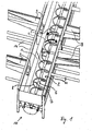
- FIG. 1 shows a device according to the invention in a perspective view.
- FIG. 2 shows a schematic longitudinal section of the arrangement according to the invention.
- FIG. 3 shows a schematic cross-sectional view of the arrangement according to the invention according to FIG . 2 .
- a device according to the invention is shown in perspective.
- a rotary member 2 is arranged, which extends substantially over the entire length of the channel 1.
- the bottom area of the Channel 1 is preferably semicircular in cross-section, so that the smallest possible distance between the rotary member 2 and the channel wall.
- the channel 1 is, for example, double-walled and executed in stainless steel.
- the rotary member 2 comprises a helical strand 8, here a tube 8 made of stainless steel, which winds around a central shaft 6 and is connected thereto via struts 7.
- the central shaft 6 is rotationally driven by a not shown drive means.
- the ice cubes 3 are conveyed in the direction of a head end 10 of the channel 1 to.
- a removal point 11 which in particular can be closed with a blocking element 12 (FIG. 2).
- the blocking member 12, for example a flap, can be arranged at both ends of the channel 1, so that it is possible to remove or loosen ice at both ends of the channel.
- the blocking member 12 is preferably used depending on the degree of opening as a metering means and is therefore particularly preferably connected to a corresponding control.
- the feeds 9 are produced according to the invention at least in part from a plastic, preferably polycarbonate. You can also be coated with the plastic. By using the plastic, the risk of damaging the ice cubes is additionally reduced.
- Moldings made of polycarbonate which is available, for example, under the trade name Makrolon, are inexpensive to produce, suitable for the processing of food and especially not very brittle at low temperatures. In the case of damage to a molded polycarbonate splinters hardly, so that virtually no Plastic splinters can get into the channel 1.
- the parts of the device according to the invention are essentially made of stainless steel, so that it is particularly easy to clean, which also improves the hygiene properties.
- a frame 14 serves, for example, for receiving the ice makers and / or for fastening the feeders 9, as well as a cover, not shown, for the channel 1.
- FIG. 2 shows an arrangement according to the invention in a section along the longitudinal direction of the channel 1.
- the rotation member is not shown here.
- the channel 1 is double-walled, which improves the thermal insulation.
- a drainage for melt water which is not shown, may be disposed in the gap.
- the channel 1 is composed of segments at the joints 15 indicated by dotted lines and can in particular be modularly expanded by adding further segments.
- the removal point comprises an opening in the channel wall at the head end 10 of the channel 1 and this opening optionally closing obturator 12.
- the head end 10 of the channel 1 is closed with the locking member 12, which may be, for example, a door or a slider. This advantageously minimizes the penetration of warm air, germs and / or contaminants.
- a device for further processing of the ice cubes can be coupled.
- the blocking member 12 is actuated, for example by a drive means 17, such as an actuator.
- ice makers 13 In which ice cubes are produced. Depending on the model of the ice maker 13 used, it is also possible to stack them one above the other, usually up to three pieces.
- the feeders 9 according to the invention are adaptable so that even higher or more distant ice makers 13 the ice cubes can be transported into the channel 1.
- FIG. 3 shows a section along the line III-III in FIG. 2.
- the person skilled in the art recognizes that the radius of the helical strand 8 of the rotary member 2 is matched to the radius of the U-shaped bottom of the channel 1, so that an effective and Gentle promotion of the ice cubes, not shown, takes place.
- the strand 8 is for example a stainless steel tube, which is connected by means of struts 7 with a central shaft 6, which may also be hollow.
- the drive of the rotary member 2, not shown, preferably takes place via the shaft 6.
- the hollow shaft 6, as well as the stainless steel tube 8 may optionally also be used for cooling the device.
- On both sides of the channel 1 are the ice makers 13, of which ice cubes on the feeders 9 slip into the gutter. Above the feeders 9, the channel 1 is closed upwards according to the invention by a cover 16, so that it forms a system closed on all sides.
Abstract
Description
Die Erfindung betrifft eine Vorrichtung zum Aufbewahren und/oder Transportieren von Eiswürfeln, die eine Rinne zur Aufbewahrung und/oder zum Transportieren der Eiswürfel aufweist, sowie eine Anordnung zur Herstellung und Bereitstellung von Eiswürfeln, mit einer solchen Vorrichtung und mit einer Mehrzahl von Eiswürfelerzeugern.The invention relates to a device for storing and / or transporting ice cubes, which has a channel for storing and / or transporting the ice cubes, and an arrangement for producing and providing ice cubes, with such a device and with a plurality of ice makers.
Maschinen zur Bereitung von Eiswürfeln sind aus dem Stand der Technik bekannt. Beispielsweise in Supermärkten, Fischereibetrieben, Eisfabriken, Catering Unternehmen, Großgastronomie oder Großmärkten, aber auch in größeren Verpflegungsstätten und Bars werden Eiswürfelmaschinen mit besonders großen Kapazitäten benötigt. Da der Bedarf an Eiswürfeln nicht konstant ist und ebenso, wie die Produktionskapazität jeder Eiswürfelmaschine verschiedenen Einflüssen unterliegt, wie insbesondere der Umgebungstemperatur, ist es in der Regel aus wirtschaftlicher Sicht vorteilhaft, mehrere Eiswürfelmaschinen vorzuhalten und diese nur entsprechend dem Bedarf zu betreiben. Industrielle Eiswürtelmaschinen weisen häufig eine Aufbewahrungsvorrichtung für fertige Eiswürfel auf, aus der diese bei Bedarf entnehmbar sind, gegebenenfalls über sogenannte Dispenser oder Spender. Der Transport der Eiswürfel erfolgt in der Regel in geeigneten Behältnissen.Machines for the preparation of ice cubes are known from the prior art. For example, in supermarkets, fishing companies, ice factories, catering companies, large catering or wholesale markets, but also in larger catering facilities and bars ice cube machines are required with particularly large capacities. Since the need for ice cubes is not constant and as well as the production capacity of each ice machine is subject to different influences, in particular the ambient temperature, it is usually advantageous from an economic point of view to hold several ice machines and operate them only according to demand. Industrial ice cube machines often have a storage device for finished ice cubes, from which they can be removed if necessary, possibly via so-called dispenser or dispenser. The transport of ice cubes usually takes place in suitable containers.
Nachteilig ist, dass die Entnahme großer Mengen von Eiswürfeln aus verschiedenen Eiswürfelmaschinen umständlich und aufwändig ist und dass der dislozierte Betrieb von gegebenenfalls gekühlten Aufbewahrungsvorrichtungen unwirtschaftlich ist. Darüber hinaus werden eine erhebliche Anzahl an Eiswürfeln bei der Entnahme durch Schütten oder mit Hilfe von Schaufeln beschädigt, was in bestimmten Bereichen, insbesondere in der Gastronomie zu Ausschuss führt. Das Umfüllen der Eiswürfel in Transportbehältnisse erfüllt die besonders hohen Hygieneanforderungen bei der Lebensmittelverarbeitung nicht immer.The disadvantage is that the removal of large quantities of ice cubes from different ice cube machines is cumbersome and expensive and that the dislocated operation of optionally cooled storage devices is uneconomical. In addition, a significant number of ice cubes are damaged during removal by pouring or with the help of blades, which leads to rejects in certain areas, especially in the catering industry. The transfer of the ice cubes into transport containers does not always meet the particularly high hygiene requirements in food processing.
Aufgabe der vorliegenden Erfindung ist es eine Vorrichtung zum Aufbewahren und/oder Transportieren von Eiswürfeln zur Verfügung zu stellen, die die Nachteile des Standes der Technik vermeidet.The object of the present invention is to provide an apparatus for storing and / or transporting ice cubes, which avoids the disadvantages of the prior art.
Die Aufgabe wird gelöst, durch eine Vorrichtung zum Aufbewahren und/oder Transportieren von Eiswürfeln mit den Merkmalen des kennzeichnenden Teils des Patentanspruchs 1 und/oder mit den Merkmalen des Patentanspruchs 5.The object is achieved by a device for storing and / or transporting ice cubes with the features of the characterizing part of patent claim 1 and / or with the features of patent claim 5.
Vorteilhafte Ausführungsformen und Weiterbildungen sind in den Unteransprüchen 2 bis 4 und 6 bis 10 angegeben.Advantageous embodiments and further developments are specified in the
Es war für den Fachmann überaus erstaunlich und nicht zu erwarten, dass die erfindungsgemäße Vorrichtung zum Aufbewahren und/oder Transportieren von Eiswürfeln weniger Energie für die Aufbewahrung von Eiswürfeln mehrerer Eiswürfelmaschinen benötigt und dass die Entnahme von Eiswürfeln besonders einfach, komfortabel möglich ist, insbesondere ohne die Eiswürfel zu beschädigen.It was extremely surprising for the skilled person and not to be expected that the device according to the invention for storing and / or transporting ice cubes requires less energy for the storage of ice cubes of several ice cube machines and that the extraction of ice cubes is particularly easy, comfortable, especially without the Damage ice cubes.
Erfindungsgemäß weist die Vorrichtung zum Aufbewahren und/oder Transportieren von Eiswürfeln eine Rinne auf. Eine Rinne im Sinne dieser Erfindung weist mindestens einen Bodenbereich und Seitenwände auf und ist beispielsweise in Form eines U und/oder V, eckig und/oder abgerundet ausgebildet. Die Erstreckung der erfindungsgemäßen Rinne in Ihrer Längsrichtung, also Transportrichtung, ist deutlich größer als die Weite der Rinne von Seitenwand zu Seitenwand. Im Bereich der Rinne können vorteilhafterweise mehrere Eiswürfelerzeuger angeordnet sein, wobei die in den Eiswürtelerzeugem hergestellten Eiswürfel in der Rinne gesammelt und aufbewahrt werden. Als Eiswürfelerzeuger wird ein Gerät bezeichnet, mit dem Eiswürfel hergestellt werden, wobei der Begriff Eiswürfel im Sinne dieser Erfindung nicht auf kubische Formen beschränkt ist. Eiswürfel können neben Volleiswürfeln in beliebiger dreidimensionaler Form auch sogenannte Hohleiswürfel sein.According to the invention, the device for storing and / or transporting ice cubes has a gutter. A gutter in the sense of this invention has at least one bottom area and side walls and is configured, for example, in the form of a U and / or V, angular and / or rounded. The extent of the channel according to the invention in its longitudinal direction, ie transport direction, is significantly greater than the width of the channel from side wall to side wall. Advantageously, several ice cube producers can be arranged in the region of the trough, the ice cubes produced in the ice cube maker being collected and stored in the trough. As an ice cube maker, a device is referred to, are made with the ice cube, wherein the term ice cube in the context of this invention is not limited to cubic forms. Ice cubes can be in addition to whole ice cubes in any three-dimensional form so-called Hohleiswürfel.
In der Rinne erstreckt sich ein Rotationsorgan im Wesentlichen über deren gesamte Länge, wobei das Rotationsorgan erfindungsgemäß drehbar angeordnet ist. Der Fachmann versteht, dass die Rotationsachse, um die das Rotationsorgan drehbar ist in Längsrichtung der Rinne verläuft. Die Eiswürfel in der Rinne sind bei einer Rotation des Rotationsorgans in einem ersten Drehsinn, also beispielsweise im Uhrzeigersinn, entlang der Rinne transportierbar. Bei einer Rotation des Rotationsorgans in einem zweiten, entgegengesetzten Drehsinn, hier also beispielsweise entgegen des Uhrzeigersinns, sind die Eiswürfel vereinzelbar.In the groove, a rotary member extends substantially over its entire length, wherein the rotary member is rotatably arranged according to the invention. The person skilled in the art will understand that the axis of rotation about which the rotary member is rotatable extends in the longitudinal direction of the channel. The ice cubes in the channel can be transported along the channel during a rotation of the rotary member in a first direction of rotation, thus for example in a clockwise direction. During a rotation of the rotary member in a second, opposite direction of rotation, in this example, for example, counterclockwise, the ice cubes are einzelzelbar.
Vereinzelung bedeutet insbesondere, dass die Eiswürfel durchmischt werden um ein Anfrieren zu unterbinden und gegebenenfalls aneinander oder an der Rinne angefrorene Eiswürfel zu trennen.Singling means, in particular, that the ice cubes are mixed in order to prevent freezing and, if appropriate, to separate ice cubes frozen against each other or on the gutter.
Mit der erfindungsgemäßen Vorrichtung ist es besonders vorteilhaft möglich, große Mengen von Eiswürfeln aufzubewahren, ohne das die Eiswürfel durch Anfrieren beschädigt werden. Der Fachmann versteht, dass sich eine Entnahmestelle beispielsweise an einem Ende der Rinne befindet, wobei der Transport der Eiswürfel durch die Rotation des Rotationsorgans in einem ersten Drehsinn vorzugsweise in Richtung einer solchen Entnahmestelle erfolgt.With the device according to the invention it is particularly advantageous possible to store large quantities of ice cubes, without the ice cubes are damaged by freezing. The person skilled in the art will understand that a removal point is located, for example, at one end of the channel, wherein the transport of the ice cubes takes place in a first direction of rotation, preferably in the direction of such a removal point, by the rotation of the rotation element.
Das erfindungsgemäße Rotationsorgan dient vorteilhafterweise als kombiniertes Transport- und Vereinzelungsorgan. Vorzugsweise kann das Rotationsorgan ausgebaut werden, was die Reinigung der erfindungsgemäßen Vorrichtung besonders einfach macht.The rotation member according to the invention is advantageously used as a combined transport and separating organ. Preferably, the rotation member can be removed, which makes the cleaning of the device according to the invention particularly simple.
Die Rotation des Rotationsorgans ist vorzugsweise mittels einer Steuerung steuerbar, beispielsweise durch einen Bediener oder automatisiert. Die Rotation in dem ersten Drehsinn ist besonders bevorzugt von einem Bedarf an Eiswürfeln abhängig, die beispielsweise an einer Entnahmestelle zur Verfügung gestellt werden. Bei einem großen Bedarf kann der Transport der Eiswürfel beispielsweise beschleunigt werden. Die Rotation in dem zweiten Drehsinn erfolgt besonders bevorzugt in festlegbaren Intervallen, beispielsweise, nachdem das Rotationsorgan eine bestimmte Zeit nicht bewegt worden ist. Durch die erfindungsgemäße Steuerung ist es vorteilhaft möglich, die benötigte Menge an Eiswürfel zur Verfügung zu stellen. Das Vereinzeln und Durchmischen der Eiswürfel kann automatisiert erfolgen, so dass es nicht zu einem Anfrieren kommen kann.The rotation of the rotary member is preferably controllable by means of a controller, for example by an operator or automated. The rotation in the first direction of rotation is particularly preferably dependent on a need for ice cubes, which are provided, for example, at a sampling point. If there is a great need, for example, the transport of the ice cubes can be accelerated. The rotation in the second direction of rotation is particularly preferably carried out at definable intervals, for example, after the rotation member has not been moved for a certain time. The inventive control, it is advantageously possible to provide the required amount of ice cubes available. The singulation and mixing of the ice cubes can be automated, so that it can not come to a freeze.
Das Rotationsorgan umfasst vorzugsweise mindestens einen helixförmig um seine Rotationsachse angeordneten Strang, wobei der Strang besonders bevorzugt ein Rohr oder Stab aus Edelstahl ist, das mittels Streben an einer zentralen Welle angeordnet ist. Das Rotationsorgan ist so vorteilhaft und einfach über die zentrale Welle rotativ antreibbar, beispielsweise durch einen Motor oder ein Getriebe. Denkbar ist auch die Anordnung von mehreren Strängen, die eine Mehrfachhelix bilden.The rotary member preferably comprises at least one strand arranged helically about its axis of rotation, wherein the strand is particularly preferably a tube or rod made of stainless steel, which is arranged by means of struts on a central shaft. The rotary member is so advantageous and easy rotatably driven via the central shaft, for example by a motor or a transmission. Also conceivable is the arrangement of several strands that are a multiple helix form.
In einer bevorzugten Ausführungsform ist die Länge der Rinne und/oder die Länge des Rotationsorgans durch modulare Erweiterung anpassbar. Die Rinne ist beispielsweise aus Rinnensegmenten zusammengesetzt und kann so vorteilhaft an die Anzahl der Eiswürfelerzeuger angepasst werden. Besonders bevorzugt ist auch das Rotationsorgan aus Segmenten zusammengesetzt und so an die Länge der Rinne anpassbar. Ein besonderer Vorteil der erfindungsgemäßen Vorrichtung liegt darin, dass sie eine große und gleichzeitig variable Speicherkapazität zur Verfügung stellt.In a preferred embodiment, the length of the channel and / or the length of the rotary member can be adapted by modular expansion. The channel is composed, for example, of channel segments and can thus be advantageously adapted to the number of ice cube producers. Particularly preferably, the rotation member is composed of segments and so adapted to the length of the groove. A particular advantage of the device according to the invention is that it provides a large and simultaneously variable storage capacity.
In einer weiteren Ausführungsform, die die Aufgabe ebenfalls löst, weist die Rinne der Vorrichtung zum Aufbewahren und/oder Transportieren von Eiswürfeln mindestens eine rutschenartige Zuführung auf, wobei die Eiswürfel von einem Eiswürfelerzeuger über die rutschenartige Zuführung in die Rinne transportierbar sind. Der Vorteil der Ausführungsform liegt darin, dass die Eiswürfel nicht in einen Aufbewahrungsbehälter fallen, sondern kontrolliert, rutschend über die Zuführung in die Rinne gelangen. Dadurch werden Beschädigungen an den Eiswürfeln durch einen Aufprall bei hoher Geschwindigkeit in vorteilhafter Weise vermieden. Besonders bevorzugt mündet die Zuführung unter einem spitzen Winkel zur Horizontalen in die Rinne. Der Winkel beträgt ganz besonders bevorzugt zwischen 0° und 25°.In a further embodiment, which also achieves the object, the channel of the device for storing and / or transporting ice cubes has at least one slide-like feed, wherein the ice cubes can be transported by an ice cube maker via the slide-like feed into the channel. The advantage of the embodiment is that the ice cubes do not fall into a storage container, but controlled, slipping over the feed into the gutter. As a result, damage to the ice cubes by impact at high speed is advantageously avoided. Particularly preferably, the feed opens at an acute angle to the horizontal in the gutter. The angle is very particularly preferably between 0 ° and 25 °.
Der Fachmann erkennt, dass bei einer Mehrzahl von Eiswürfelerzeugem für jeden Eiswürfelerzeuger eine Zuführung vorgesehen sein kann. Es wäre auch denkbar, die Eiswürfel mehrerer Eiswürfelerzeuger über eine Zuführung gesammelt in die Rinne zu transportieren. Die erfindungsgemäßen Zuführungen sind vorzugsweise anpassbar, insbesondere in der Länge, so dass die Position der Eiswürfelerzeuger zur Rinne in vorteilhafter Weise variierbar ist. Beispielsweise können die Eiswürfelerzeuger unterschiedlich weit von der Rinne entfernt angeordnet sein, oder insbesondere in unterschiedlicher Höhe.The person skilled in the art recognizes that a supply can be provided for a plurality of ice cube producers for each ice cube producer. It would also be conceivable to transport the ice cubes of several ice cube generators collected via a feed into the gutter. The feeders according to the invention are preferably adaptable, in particular in length, so that the position of the ice cube generators to the trough can advantageously be varied. For example, the ice cube generators can be arranged at different distances from the channel, or in particular at different heights.
Die Zuführung kann aus einem beliebigen, geeigneten Material hergestellt sein. Vorzugsweise besteht die Zuführung zumindest teilweise aus einem Kunststoff und/oder ist zumindest teilweise mit einem Kunststoff beschichtet, besonders bevorzugt Polycarbonat. Die Eiswürfel werden vorteilhafterweise durch die glatte und vergleichsweise nachgiebige Oberfläche des Kunststoffs nicht beschädigt.The feeder may be made of any suitable material. Preferably, the supply consists at least partially of a plastic and / or is at least partially coated with a plastic, more preferably polycarbonate. The ice cubes are advantageously not damaged by the smooth and comparatively compliant surface of the plastic.
In einer bevorzugten Ausführungsform ist die Rinne doppelwandig ausgeführt ist, besonders bevorzugt aus Edelstahl. Die Doppelwand erlaubt beispielsweise eine besonders gute thermische Isolierung der Rinne, so dass die Temperierung der Eiswürfel weniger aufwändig ist. Edelstahl ist besonders haltbar und unempfindlich. Die Vorrichtung ist daher besonders leicht zu reinigen.In a preferred embodiment, the channel is designed double-walled, particularly preferably made of stainless steel. The double wall allows, for example, a particularly good thermal insulation of the channel, so that the temperature of the ice cubes is less expensive. Stainless steel is particularly durable and insensitive. The device is therefore particularly easy to clean.
Ebenfalls bevorzugt weist die Rinne eine Abdeckung auf, die die Rinne nach oben hin weitgehend verschließt. Die erfindungsgemäße Vorrichtung bildet vorzugsweise ein allseitig geschlossenes System. Dadurch wird besonders vorteilhaft das Eindringen von Keimen und/oder Verschmutzungen in die Rinne unterbunden, so dass besonders hohe Hygieneanforderungen erfüllt werden.Also preferably, the channel has a cover which largely closes the channel towards the top. The device according to the invention preferably forms an all-sided closed system. As a result, the penetration of germs and / or contamination into the channel is prevented in a particularly advantageous manner, so that particularly high hygiene requirements are met.
In einer weiteren bevorzugten Ausführungsform weist die Rinne an mindestens einem Kopfende eine Öffnung als Entnahmestelle auf, die durch ein Sperrorgan verschließbar ist. Durch die Bereitstellung der Eiswürfel an der Entnahmestelle sind diese besonders komfortabel entnehmbar. Das Sperrorgan, beispielsweise ein Schieber, verhindert den Austritt von Eiswürfeln und eine Erwärmung des Innenraums der Rinne, während keine Entnahme von Eiswürfeln erfolgt. Insbesondere wird vorteilhaft das Eindringen von Keimen und/oder Verunreinigungen über die Entnahmestelle minimiert.In a further preferred embodiment, the channel has at least one head end an opening as a removal point, which can be closed by a locking member. By providing the ice cubes at the sampling point, they are particularly easy to remove. The obturator, such as a slide, prevents the escape of ice cubes and heating of the interior of the trough, while no removal of ice cubes takes place. In particular, the penetration of germs and / or contaminants via the removal point is advantageously minimized.
Vorzugsweise ist eine Vorrichtung zur Weiterverarbeitung der Eiswürfel an dem Kopfende der Rinne ankoppelbar, beispielsweise ein Dispenser oder eine Verpackungsmaschine, die besonders bevorzugt mit einer Wiegevorrichtung ausgestattet ist. Der Fachmann erkennt, dass die erfindungsgemäße Vorrichtung ein im Wesentlichen allseitig abgeschlossenes System ist, so dass die Temperatur im Inneren besonders konstant ist und vorteilhafterweise besonders hohe Hygieneanforderungen erfüllt werden. Bei einer direkten Abgabe der Eiswürfel von der Rinne an die Vorrichtung zu7r Weiterverarbeitung über die Entnahmestelle, kommen die Eiswürfel vorteilhaftennreise nicht mit der Umgebung in Kontakt.Preferably, a device for further processing of the ice cubes at the head end of the channel can be coupled, for example, a dispenser or a packaging machine, which is particularly preferably equipped with a weighing device. The person skilled in the art recognizes that the device according to the invention is a system which is essentially closed on all sides, so that the temperature inside is particularly constant and advantageously particularly high hygiene requirements are met. In the case of a direct delivery of the ice cubes from the channel to the device for further processing via the removal point, the ice cube will not come into contact with the environment.
Ebenfalls bevorzugt weist die Rinne eine Drainage für Schmelzwasser auf, die beispielsweise im Zwischenraum der Doppelwand verläuft.Also preferably, the channel has a drainage for melt water, which runs for example in the space between the double wall.
Ein weiterer Gegenstand der Erfindung ist eine Anordnung zur Herstellung und Bereitstellung von Eiswürfeln, mit einer zuvor beschriebenen, erfindungsgemäßen Vorrichtung und einer Mehrzahl von Eiswürfelerzeugem, wobei die Eiswürfelerzeuger beiderseits der Rinne angeordnet sein können, und zwar mehrere Eiswürfelerzeuger entlang der Rinne hintereinander und/oder mehrere Eiswürfelerzeuger übereinander.Another object of the invention is an arrangement for producing and providing ice cubes, with a device according to the invention described above and a plurality of ice makers, wherein the ice maker can be arranged on both sides of the channel, namely several ice makers along the channel behind one another and / or more Ice cube maker on top of each other.
Die Anordnung hat den Vorteil, dass die Kapazität zur Herstellung von Eiswürfeln an den Bedarf anpassbar ist, indem gerade so viele Eiswürfelerzeuger darin angeordnet sind und/oder in Betrieb sind, wie nötig. Die Aufbewahrung der Eiswürfel in der erfindungsgemäßen Rinne erlaubt vorteilhaft eine effektivere Temperierung als bei einzelnen Behältern je Eiswürfelerzeuger. Außerdem können die Eiswürfel komfortabel an einer gemeinsamen Entnahmestelle bereitgestellt werden. Die erfindungsgemäße Anordnung weist eine große und gleichzeitig variable Speicherkapazität auf.The arrangement has the advantage that the capacity for making ice cubes is adaptable to the need by having just as many ice makers thereon and / or operating as needed. The storage of the ice cubes in the channel according to the invention advantageously allows a more effective temperature control than in individual containers per ice cube maker. In addition, the ice cubes can be conveniently provided at a common sampling point. The arrangement according to the invention has a large and simultaneously variable storage capacity.
Nachfolgend wir die Erfindung anhand von Zeichnungen erläutert. Die Darstellungen sind lediglich beispielhaft und schränken den allgemeinen Erfindungsgedanken nicht ein.Hereinafter, the invention will be explained with reference to drawings. The illustrations are merely exemplary and do not limit the general idea of the invention.
Figur 1 zeigt eine erfindungsgemäße Vorrichtung in einer perspektivischen Ansicht. FIG. 1 shows a device according to the invention in a perspective view.
Figur 2 zeigt einen schematischen Längsschnitt der erfindungsgemäßen Anordnung. FIG. 2 shows a schematic longitudinal section of the arrangement according to the invention.
Figur 3 zeigt eine schematische Querschnittdarstellung der erfindungsgemäßen Anordnung gemäß Figur 2. FIG. 3 shows a schematic cross-sectional view of the arrangement according to the invention according to FIG . 2 .
In der Figur 1 ist eine erfindungsgemäße Vorrichtung perspektivisch dargestellt. Innerhalb einer Rinne 1 ist ein Rotationsorgan 2 angeordnet, das sich im Wesentlichen über die gesamte Länge der Rinne 1 erstreckt. Der Bodenbereich der Rinne 1 ist vorzugsweise im Querschnitt halbkreisförmig ausgebildet, so dass ein möglichst geringer Abstand zwischen dem Rotationsorgan 2 und der Rinnenwand besteht. Die Rinne 1 ist beispielsweise doppelwandig und in Edelstahl ausgeführt. Das Rotationsorgan 2 umfasst einen helixförmigen Strang 8, hier ein Rohr 8 aus Edelstahl, das sich um eine zentrale Welle 6 windet und mit diesem über Streben 7 verbunden ist. Die zentrale Welle 6 wird durch ein nicht dargestelltes Antriebsmittel rotativ angetrieben. Durch eine Rotation des Rotationsorgans 8 im Uhrzeigersinn entsprechend Pfeil 4 werden die Eiswürfel 3 in Richtung auf ein Kopfende 10 der Rinne 1 zu gefördert. Am Kopfende 10 befindet sich beispielsweise eine Entnahmestelle 11, die insbesondere mit einem Sperrorgan 12 verschließbar ist (Figur 2). Eine Rotation des Rotationsorgans 8 im Uhrzeigersinn, entsprechend Pfeil 5 bewirkt dagegen eine Vereinzelung der Eiswürfel, die nicht dargestellt sind, indem diese durchmischt und aufgelockert werden. Das Sperrorgan 12, beispielsweise eine Klappe kann an beiden Enden der Rinne 1 angeordnet sein, so dass es möglich ist an beiden Enden der Rinne Eis zu entnehmen bzw. aufzulockern. Das Sperrorgan 12 dient vorzugsweise je nach Öffnungsgrad als Mengendosier-Mittel und ist dementsprechend besonders bevorzugt an eine entsprechende Regelung angeschlossen.In the figure 1 , a device according to the invention is shown in perspective. Within a channel 1, a
Von beiden Seiten der Rinne 1 münden Zuführungen 9 in diese hinein. Über die Zuführungen 9 gelangen die Eiswürfel von Eiserzeugem 13 (Figur 2) in die Rinne 1. Der Winkel zwischen der Ebene in der die Eiswürfel in den Zuführungen rutschen und der Horizontalen ist spitz. Durch die flache Rutschbahn der Eiswürfel in den Zuführungen 9 werden deutlich weniger Eiswürfel durch den Aufprall beschädigt. Dies ist insbesondere bei sogenannten Hohleiswürfeln wichtig, die weniger stabil sind, als Volleiswürfel. Die Zuführungen 9 sind erfindungsgemäß zumindest zum Teil aus einem Kunststoff hergestellt, vorzugsweise Polycarbonat. Sie können außerdem mit dem Kunststoff beschichtet sein. Durch die Verwendung des Kunststoffs ist die Gefahr der Beschädigung der Eiswürfel zusätzlich vermindert. Formteile aus Polycarbonat, das beispielsweise unter dem Handelsnamen Makrolon erhältlich ist, sind kostengünstig herzustellen, für die Verarbeitung von Lebensmitteln geeignet und insbesondere auch bei tiefen Temperaturen nicht sehr spröde. Im Falle einer Beschädigung eines Formteils splittert Polycarbonat kaum, so dass praktisch keine Kunststoffsplitter in die Rinne 1 gelangen können.From both sides of the channel 1 feeds 9 open into this. The ice cubes of ice makers 13 (FIG. 2) enter the channel 1 via the feeders 9. The angle between the plane in which the ice cubes slide in the feeders and the horizontal is acute. The flat slide of the ice cubes in the feeders 9 significantly less ice cubes are damaged by the impact. This is particularly important in so-called Hohleiswürfeln that are less stable than full ice cubes. The feeds 9 are produced according to the invention at least in part from a plastic, preferably polycarbonate. You can also be coated with the plastic. By using the plastic, the risk of damaging the ice cubes is additionally reduced. Moldings made of polycarbonate, which is available, for example, under the trade name Makrolon, are inexpensive to produce, suitable for the processing of food and especially not very brittle at low temperatures. In the case of damage to a molded polycarbonate splinters hardly, so that virtually no Plastic splinters can get into the channel 1.
Im Übrigen sind die Teile der erfindungsgemäßen Vorrichtung im Wesentlichen aus Edelstahl gefertigt, so dass diese besonders leicht zu reinigen ist, was auch die Hygieneeigenschaften verbessert.Incidentally, the parts of the device according to the invention are essentially made of stainless steel, so that it is particularly easy to clean, which also improves the hygiene properties.
Ein Rahmen 14 dient beispielsweise zur Aufnahme der Eiserzeuger und/oder zur Befestigung der Zuführungen 9, sowie einer nicht dargestellten Abdeckung für die Rinne 1.A
In der Figur 2 ist eine erfindungsgemäße Anordnung in einem Schnitt entlang der Längsrichtung der Rinne 1 dargestellt. Das Rotationsorgan ist hier nicht dargestellt. Die Rinne 1 ist doppelwandig ausgeführt, was die thermische Isolierung verbessert. Außerdem kann eine Drainage für Schmelzwasser, die nicht dargestellt ist, in dem Zwischenraum angeordnet sein. Die Rinne 1 ist erfindungsgemäß aus Segmenten an den durch punktierte Linien angedeuteten Fügestellen 15 zusammengesetzt und kann insbesondere durch Hinzufügen von weiteren Segmenten modular erweitert werden. An dem Kopfende 10 der Rinne 1 befindet sich eine Entnahmestelle 11 für die nicht dargestellten Eiswürfel, wobei die Entnahmestelle eine Öffnung in der Rinnenwand am Kopfende 10 der Rinne 1 und ein diese Öffnung wahlweise verschließendes Sperrorgan 12 umfasst. Während keine Entnahme erfolgt, ist das Kopfende 10 der Rinne 1 mit dem Sperrorgan 12 verschlossen, das beispielsweise eine Tür oder ein Schieber sein kann. Dadurch wird vorteilhaft das Eindringen von Warmluft, Keimen und/oder Verunreinigungen minimiert. Im Bereich der Entnahmestelle 11 kann eine Vorrichtung zur Weiterverarbeitung der Eiswürfel ankoppelbar sein. Das Sperrorgan 12 ist beispielsweise durch ein Antriebsmittel 17, wie einen Stellantrieb betätigbar.FIG. 2 shows an arrangement according to the invention in a section along the longitudinal direction of the channel 1. The rotation member is not shown here. The channel 1 is double-walled, which improves the thermal insulation. In addition, a drainage for melt water, which is not shown, may be disposed in the gap. According to the invention, the channel 1 is composed of segments at the
Entlang der Rinne 1, in Transportrichtung hintereinander angeordnet, befinden sich Eiserzeuger 13 in denen Eiswürfel produziert werden. Je nach Modell des verwendeten Eiserzeugers 13 ist es auch möglich, diese übereinander zu stapeln, in der Regel bis zu drei Stück. Die erfindungsgemäßen Zuführungen 9 sind so anpassbar, dass auch von höher oder weiter entfernt angeordneten Eiserzeugem 13 die Eiswürfel in die Rinne 1 transportiert werden können.Along the channel 1, arranged one behind the other in the direction of transport, there are
Die Figur 3 zeigt einen Schnitt entlang der Linie III-III in der Figur 2. Der Fachmann erkennt, dass der Radius des helixförmigen Strangs 8 des Rotationsorgans 2 auf den Radius des U-förmigen Bodens der Rinne 1 so abgestimmt ist, dass eine effektive und schonende Förderung der nicht dargestellten Eiswürfel erfolgt. Der Strang 8 ist beispielsweise ein Edelstahlrohr, das mittels Streben 7 mit einer zentralen Welle 6 verbunden, die ebenfalls hohl sein kann. Der nicht dargestellte Antrieb des Rotationsorgans 2 erfolgt vorzugsweise über die Welle 6. Die Hohlwelle 6, sowie das Edelstahlrohr 8 können gegebenenfalls auch zur Kühlung der Vorrichtung eingesetzt werden. Auf beiden Seiten der Rinne 1 befinden sich die Eiserzeuger 13, von denen Eiswürfel über die Zuführungen 9 rutschend in die Rinne gelangen. Oberhalb der Zuführungen 9 ist die Rinne 1 nach oben erfindungsgemäß durch eine Abdeckung 16 verschlossen, so dass sie ein allseitig abgeschlossenes System bildet. FIG. 3 shows a section along the line III-III in FIG. 2. The person skilled in the art recognizes that the radius of the helical strand 8 of the
- 11
- Rinnegutter
- 22
- Rotationsorganrotary member
- 33
- Eiswürfelice cubes
- 44
- Erster DrehsinnFirst turn
- 55
- Zweiter DrehsinnSecond sense of rotation
- 66
- Zentrale WelleCentral shaft
- 77
- Strebestrut
- 88th
- Strangstrand
- 99
- Zuführungfeed
- 1010
- Kopfendehead
- 1111
- Entnahmestellesampling point
- 1212
- Sperrorganblocking member
- 1313
- Eiserzeugerice maker
- 1414
- Rahmenframe
- 1515
- Fügestellejoint
- 1616
- Abdeckungcover
- 1717
- Antriebsmitteldrive means
Claims (12)
Applications Claiming Priority (1)
| Application Number | Priority Date | Filing Date | Title |
|---|---|---|---|
| DE10612700 | 2006-03-17 |
Publications (2)
| Publication Number | Publication Date |
|---|---|
| EP1835245A2 true EP1835245A2 (en) | 2007-09-19 |
| EP1835245A3 EP1835245A3 (en) | 2012-05-09 |
Family
ID=38222106
Family Applications (1)
| Application Number | Title | Priority Date | Filing Date |
|---|---|---|---|
| EP07005444A Withdrawn EP1835245A3 (en) | 2006-03-17 | 2007-03-16 | Device for storing and/or transporting ice cubes |
Country Status (1)
| Country | Link |
|---|---|
| EP (1) | EP1835245A3 (en) |
Citations (7)
| Publication number | Priority date | Publication date | Assignee | Title |
|---|---|---|---|---|
| US3225968A (en) * | 1964-01-06 | 1965-12-28 | Whirlpool Co | Ice maker dispensing apparatus |
| US3929196A (en) * | 1974-04-26 | 1975-12-30 | Uuno Rantanen | Ice auger |
| US3930377A (en) * | 1973-09-17 | 1976-01-06 | King-Seeley Thermos Co. | Ice transport system |
| US4438634A (en) * | 1982-11-05 | 1984-03-27 | General Mills, Inc. | Freeze concentration apparatus |
| US5056688A (en) * | 1990-01-02 | 1991-10-15 | Amana Refrigeration Inc. | Ice cube and crushed ice dispenser |
| EP0828120A1 (en) * | 1996-08-16 | 1998-03-11 | Wessamat Eismaschinen Fabrik GmbH | Device for delivering metered quantities of ice cubes |
| WO2000008396A1 (en) * | 1998-08-03 | 2000-02-17 | Lancer Ice Link, L.L.C. | Vacuum pneumatic system for conveyance of ice |
-
2007
- 2007-03-16 EP EP07005444A patent/EP1835245A3/en not_active Withdrawn
Patent Citations (7)
| Publication number | Priority date | Publication date | Assignee | Title |
|---|---|---|---|---|
| US3225968A (en) * | 1964-01-06 | 1965-12-28 | Whirlpool Co | Ice maker dispensing apparatus |
| US3930377A (en) * | 1973-09-17 | 1976-01-06 | King-Seeley Thermos Co. | Ice transport system |
| US3929196A (en) * | 1974-04-26 | 1975-12-30 | Uuno Rantanen | Ice auger |
| US4438634A (en) * | 1982-11-05 | 1984-03-27 | General Mills, Inc. | Freeze concentration apparatus |
| US5056688A (en) * | 1990-01-02 | 1991-10-15 | Amana Refrigeration Inc. | Ice cube and crushed ice dispenser |
| EP0828120A1 (en) * | 1996-08-16 | 1998-03-11 | Wessamat Eismaschinen Fabrik GmbH | Device for delivering metered quantities of ice cubes |
| WO2000008396A1 (en) * | 1998-08-03 | 2000-02-17 | Lancer Ice Link, L.L.C. | Vacuum pneumatic system for conveyance of ice |
Also Published As
| Publication number | Publication date |
|---|---|
| EP1835245A3 (en) | 2012-05-09 |
Similar Documents
| Publication | Publication Date | Title |
|---|---|---|
| DE2108031C3 (en) | Ice dispenser for the optional delivery of ice cubes or crushed ice cubes | |
| EP1955604B1 (en) | Method and device for filling containers with rod-shaped objects | |
| DE102007034084B3 (en) | Device for charging and discharging an adjusting plate of a freeze drying installation comprises a sliding element having a loading element and a removal slide | |
| EP2019277B1 (en) | Apparatus for loading and unloading an adjustable plate of a freeze-drying plant and corresponding method | |
| EP1698554B1 (en) | Feeder tube for tablets | |
| DE102006061094A1 (en) | ice dispenser | |
| DE2421667A1 (en) | DEVICE AND METHOD FOR FREEZING MATERIAL | |
| DE69925498T2 (en) | AUTOMATIC WAREHOUSE | |
| DE202007013714U1 (en) | Ice crusher for an icemaker | |
| DE1947219A1 (en) | Apparatus for handling mold charge quantities of molten glass | |
| DE202018103325U1 (en) | Schneckenrührwerk | |
| WO2004066747A9 (en) | Device for inserting sticks into molds for producing confectionery on a stick | |
| BE1020389A3 (en) | DEVICE FOR ARRANGING SHAPES ON PALLETS OR OTHER DOCUMENTS. | |
| EP1835245A2 (en) | Device for storing and/or transporting ice cubes | |
| DE102006012700A1 (en) | Device for storing and transporting ice cubes, has chute and rotating element, which extends over entire length of chute, where ice cubes are transported along chute during rotation of rotating element in pivoting mode | |
| EP1821268B9 (en) | Food dispensing apparatus | |
| EP2457443B1 (en) | Method for mechanical twisting of dough strips | |
| EP3418227B1 (en) | Rail-bound transport robot and method for operating a rail-bound transport robot | |
| DE102019126752A1 (en) | Device and method for converting a single-row product flow into a multi-row product flow | |
| DE3541455C2 (en) | ||
| DE102004013178A1 (en) | Peeling machine for asparagus stalks has spiral magazine at top holding asparagus stalks upright and dropping them vertically past transport rollers and peeling knife into second magazine at bottom | |
| DE19642002A1 (en) | Device for storing and dispensing individual portions of frozen food | |
| DE60101404T2 (en) | Bearings for bars | |
| DE1944142C3 (en) | Ice dispenser for ice cubes and crushed ice | |
| DE1632995C3 (en) |
Legal Events
| Date | Code | Title | Description |
|---|---|---|---|
| PUAI | Public reference made under article 153(3) epc to a published international application that has entered the european phase |
Free format text: ORIGINAL CODE: 0009012 |
|
| AK | Designated contracting states |
Kind code of ref document: A2 Designated state(s): AT BE BG CH CY CZ DE DK EE ES FI FR GB GR HU IE IS IT LI LT LU LV MC MT NL PL PT RO SE SI SK TR |
|
| AX | Request for extension of the european patent |
Extension state: AL BA HR MK YU |
|
| PUAL | Search report despatched |
Free format text: ORIGINAL CODE: 0009013 |
|
| AK | Designated contracting states |
Kind code of ref document: A3 Designated state(s): AT BE BG CH CY CZ DE DK EE ES FI FR GB GR HU IE IS IT LI LT LU LV MC MT NL PL PT RO SE SI SK TR |
|
| AX | Request for extension of the european patent |
Extension state: AL BA HR MK RS |
|
| RIC1 | Information provided on ipc code assigned before grant |
Ipc: F25C 5/00 20060101AFI20120330BHEP |
|
| AKY | No designation fees paid | ||
| REG | Reference to a national code |
Ref country code: DE Ref legal event code: R108 |
|
| REG | Reference to a national code |
Ref country code: DE Ref legal event code: R108 Effective date: 20130116 |
|
| STAA | Information on the status of an ep patent application or granted ep patent |
Free format text: STATUS: THE APPLICATION IS DEEMED TO BE WITHDRAWN |
|
| 18D | Application deemed to be withdrawn |
Effective date: 20121110 |