EP1835147A2 - Turbofan - Google Patents
Turbofan Download PDFInfo
- Publication number
- EP1835147A2 EP1835147A2 EP07103469A EP07103469A EP1835147A2 EP 1835147 A2 EP1835147 A2 EP 1835147A2 EP 07103469 A EP07103469 A EP 07103469A EP 07103469 A EP07103469 A EP 07103469A EP 1835147 A2 EP1835147 A2 EP 1835147A2
- Authority
- EP
- European Patent Office
- Prior art keywords
- turbine
- fan
- blades
- extending
- fan blades
- Prior art date
- Legal status (The legal status is an assumption and is not a legal conclusion. Google has not performed a legal analysis and makes no representation as to the accuracy of the status listed.)
- Granted
Links
Images

Classifications
-
- F—MECHANICAL ENGINEERING; LIGHTING; HEATING; WEAPONS; BLASTING
- F02—COMBUSTION ENGINES; HOT-GAS OR COMBUSTION-PRODUCT ENGINE PLANTS
- F02K—JET-PROPULSION PLANTS
- F02K3/00—Plants including a gas turbine driving a compressor or a ducted fan
- F02K3/02—Plants including a gas turbine driving a compressor or a ducted fan in which part of the working fluid by-passes the turbine and combustion chamber
- F02K3/04—Plants including a gas turbine driving a compressor or a ducted fan in which part of the working fluid by-passes the turbine and combustion chamber the plant including ducted fans, i.e. fans with high volume, low pressure outputs, for augmenting the jet thrust, e.g. of double-flow type
- F02K3/062—Plants including a gas turbine driving a compressor or a ducted fan in which part of the working fluid by-passes the turbine and combustion chamber the plant including ducted fans, i.e. fans with high volume, low pressure outputs, for augmenting the jet thrust, e.g. of double-flow type with aft fan
-
- F—MECHANICAL ENGINEERING; LIGHTING; HEATING; WEAPONS; BLASTING
- F02—COMBUSTION ENGINES; HOT-GAS OR COMBUSTION-PRODUCT ENGINE PLANTS
- F02C—GAS-TURBINE PLANTS; AIR INTAKES FOR JET-PROPULSION PLANTS; CONTROLLING FUEL SUPPLY IN AIR-BREATHING JET-PROPULSION PLANTS
- F02C3/00—Gas-turbine plants characterised by the use of combustion products as the working fluid
- F02C3/04—Gas-turbine plants characterised by the use of combustion products as the working fluid having a turbine driving a compressor
- F02C3/06—Gas-turbine plants characterised by the use of combustion products as the working fluid having a turbine driving a compressor the compressor comprising only axial stages
- F02C3/073—Gas-turbine plants characterised by the use of combustion products as the working fluid having a turbine driving a compressor the compressor comprising only axial stages the compressor and turbine stages being concentric
-
- F—MECHANICAL ENGINEERING; LIGHTING; HEATING; WEAPONS; BLASTING
- F02—COMBUSTION ENGINES; HOT-GAS OR COMBUSTION-PRODUCT ENGINE PLANTS
- F02C—GAS-TURBINE PLANTS; AIR INTAKES FOR JET-PROPULSION PLANTS; CONTROLLING FUEL SUPPLY IN AIR-BREATHING JET-PROPULSION PLANTS
- F02C7/00—Features, components parts, details or accessories, not provided for in, or of interest apart form groups F02C1/00 - F02C6/00; Air intakes for jet-propulsion plants
- F02C7/04—Air intakes for gas-turbine plants or jet-propulsion plants
- F02C7/042—Air intakes for gas-turbine plants or jet-propulsion plants having variable geometry
-
- F—MECHANICAL ENGINEERING; LIGHTING; HEATING; WEAPONS; BLASTING
- F05—INDEXING SCHEMES RELATING TO ENGINES OR PUMPS IN VARIOUS SUBCLASSES OF CLASSES F01-F04
- F05D—INDEXING SCHEME FOR ASPECTS RELATING TO NON-POSITIVE-DISPLACEMENT MACHINES OR ENGINES, GAS-TURBINES OR JET-PROPULSION PLANTS
- F05D2240/00—Components
- F05D2240/80—Platforms for stationary or moving blades
-
- Y—GENERAL TAGGING OF NEW TECHNOLOGICAL DEVELOPMENTS; GENERAL TAGGING OF CROSS-SECTIONAL TECHNOLOGIES SPANNING OVER SEVERAL SECTIONS OF THE IPC; TECHNICAL SUBJECTS COVERED BY FORMER USPC CROSS-REFERENCE ART COLLECTIONS [XRACs] AND DIGESTS
- Y02—TECHNOLOGIES OR APPLICATIONS FOR MITIGATION OR ADAPTATION AGAINST CLIMATE CHANGE
- Y02T—CLIMATE CHANGE MITIGATION TECHNOLOGIES RELATED TO TRANSPORTATION
- Y02T50/00—Aeronautics or air transport
- Y02T50/60—Efficient propulsion technologies, e.g. for aircraft
Definitions
- This invention relates generally to gas turbine engines and more particularly to an aft fan for a gas turbine engine.
- a gas turbine engine includes a compressor that provides pressurized air to a combustor wherein the air is mixed with fuel and ignited for generating hot combustion gases. These gases flow downstream to one or more turbines that extract energy therefrom to power the compressor and provide useful work such as powering an aircraft in flight.
- a turbofan engine which typically includes a fan placed at the front of the core engine, a high pressure turbine powers the compressor of the core engine. A low pressure turbine is disposed downstream from the high pressure turbine for powering the fan.
- a fan assembly for a gas turbine engine including: a turbine rotor adapted to be disposed aft of a core of the gas turbine engine; a row of turbine blades carried by the rotor, each turbine blade extending from the rotor to a tip, the turbine blades adapted to extract energy from a stream of pressurized combustion gases generated by the core; and at least two rows of axially-spaced apart, radially-extending fan blades carried by the row of turbine blades for rotation therewith.
- a gas turbine engine includes a core for generating a stream of pressurized combustion gases, including in sequential flow order: a compressor, a combustor, and a high-pressure turbine; and a fan assembly having a turbine rotor and disposed aft of the core; a row of turbine blades carried by said rotor, each turbine blade extending from the rotor to a tip, said turbine blades adapted to extract energy from the combustion gases; and at least two rows of axially-spaced apart, radially-extending fan blades carried by the row of turbine blades for rotation therewith.
- Figure 1 illustrates a representative gas turbine engine, generally designated 10.
- the engine 10 has a longitudinal center line or axis A and an outer stationary annular casing 12 disposed concentrically about and coaxially along the axis A.
- the engine 10 has a high-pressure compressor 14, combustor 16, and high pressure turbine (“HPT") 18 arranged in serial flow relationship, collectively forming a core 20.
- a forward compressor rotor (e.g., low-pressure compressor, fan, or booster) 22 may be provided, driven by a low-pressure turbine 24 through an LP shaft 26.
- pressurized air from the compressor 14 is mixed with fuel in the combustor 16 and ignited, thereby generating combustion gases. Some work is extracted from these gases by the high pressure turbine 18 which drives the compressor 14 via shaft 28, and by the low pressure turbine 24, which drives the booster 22. The combustion gases then flow into an aft fan assembly 30 disposed aft of the core 20.
- the aft fan assembly 30 comprises a free turbine or work turbine 32 which drives an integral aft fan 34.
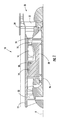
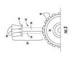
- FIGS 2 and 3 illustrate the aft fan assembly 30 in more detail.
- the aft fan assembly 30 includes a hub or rotor 36 carrying a plurality of compound blades 38 in dovetail slots 40 and extending radially therefrom.
- Each of the compound blades 38 includes a turbine blade 42, an arcuate platform segment 44, and a plurality of fan blades 46.
- each compound blade 38 including the turbine blade 42, its platform segment 44, and the associated fan blades 46 is made as an integral component, for example by casting, forging, machining, or by fabrication (e.g. welding, brazing) from sub-components.
- the compound blades 38 could also be built-up as a mechanical assembly of individual components.
- Each of the turbine blades 42 is an airfoil having a leading edge 48, a trailing edge 50, a tip 52, a root 54, a convex suction side 56, and a concave pressure side 58.
- the turbine blades 42 are shaped to extract energy from the stream of pressurized gases exiting the core 20 to turn the rotor 36.
- the turbine blades 42 may be provided with internal channels (not shown) connected to a source of cooling air to lower their temperature.
- Each platform segment 44 extends away from the associated turbine blade 42 in axial and circumferential directions.
- the platform segments 44 abut each other and collectively define an annular platform 60 interconnecting the tips 52 of the turbine blades 42.
- the fan blades 46 are grouped into circumferential arrays referred to as "rows" or “stages".
- a row 62 of first fan blades 46A extends radially outward from the platform 60.
- Each of the first fan blades 46A is an airfoil having leading and trailing edges, a tip and a root, and opposed pressure and suction sides.
- a row 72 of second fan blades 46B extends radially outward from the platform 60, downstream of the first fan blades 46A.
- Each of the second fan blades 46B is an airfoil having leading and trailing edges, a tip and a root, and opposed pressure and suction sides.
- the number of fan blades 46 in each row 62 and 72 will vary depending on the specific application.
- the fan blades 46 have a reduced chord as compared to prior art fan-on-turbine designs.
- a greater number of fan blades 46A and 46B are used in each of the rows 62 and 72, as compared to a prior art fan-on-turbine design.
- three first fan blades 46A and three second fan blades 46B extend from each platform segment 44, for a total of six fan blades 46 per turbine blade 42. Greater or lesser numbers of fan blades 46 may be used for each turbine blade 42 to suit a specific application.
- the fan blades 46 are surrounded by an annular casing 82 having inner and outer walls 84 and 86.
- the inner surface of the outer wall 86 defines the outer boundary of a bypass duct 88 and the outer surface of the inner wall 84 defines the inner boundary of the bypass duct 88, in cooperation with the platform 60.
- a circumferential array of airfoil-shaped fan stator vanes 90 extends radially inward into the bypass duct 88 between the first and second fan rows 62 and 72, and serves to redirect air flow exiting the first fan blades 46A into the second fan blades 46B at a desired angle.
- a circumferential array of radially-extending, airfoil-shaped inlet guide vanes (“IGVs”) 92 may be disposed in the bypass duct 88 forward of the fan blades 46.
- the IGVs 92, or portions thereof, are moveable so as to change their effective angle of attack relative to the air flow entering the bypass duct 88.
- the IGVs 92 may be adjusted during engine operation to modulate air flow through the aft fan 34.
- the IGVs may be operated using appropriate actuators 94 under the control of a FADEC, PMC, manual control, or other known type of engine control (not shown).
- a circumferential array of radially-extending, airfoil-shaped outlet guide vanes (“OGVs”) 96 is also disposed in the bypass duct 88, aft of the fan blades 46.
- the above-described aft fan assembly 30 is able to achieve greater work input than prior art fan-on-turbine designs without adding the complexity of additional turbine stages. For example, if a single fan stage that is capable of producing a pressure ratio of about 2.0 at a design operating condition, the two-stage design described above could enable a pressure ratio of about 3.5. To the extent that enough energy is available from the turbine 32, more stages of fan blades 46 could be added.
Landscapes
- Engineering & Computer Science (AREA)
- Chemical & Material Sciences (AREA)
- Combustion & Propulsion (AREA)
- Mechanical Engineering (AREA)
- General Engineering & Computer Science (AREA)
- Physics & Mathematics (AREA)
- Geometry (AREA)
- Structures Of Non-Positive Displacement Pumps (AREA)
- Turbine Rotor Nozzle Sealing (AREA)
Abstract
Description
- This invention relates generally to gas turbine engines and more particularly to an aft fan for a gas turbine engine.
- A gas turbine engine includes a compressor that provides pressurized air to a combustor wherein the air is mixed with fuel and ignited for generating hot combustion gases. These gases flow downstream to one or more turbines that extract energy therefrom to power the compressor and provide useful work such as powering an aircraft in flight. In a turbofan engine, which typically includes a fan placed at the front of the core engine, a high pressure turbine powers the compressor of the core engine. A low pressure turbine is disposed downstream from the high pressure turbine for powering the fan.
- Some prior art engine configurations incorporate an aft fan stage integral with a turbine rotor. There are several potential advantages for this "fan on turbine" configuration, which eliminates the drive shaft required in a front-fan engine. It is desired to have such a fan-on-turbine with a design pressure ratio (i.e. the ratio of total pressure at the fan exit to the total pressure at the fan inlet) of about 2.5 or greater. Unfortunately, the high tip speed required for a single fan stage to produce this pressure ratio is contrary the AN2 and radius ratio constraints dictated by accepted turbine design practice.
- Accordingly, there is a need for a fan-on-turbine configuration which achieves a high pressure ratio.
- The above-mentioned need is addressed by the present invention, which according to one aspect provides a fan assembly for a gas turbine engine, including: a turbine rotor adapted to be disposed aft of a core of the gas turbine engine; a row of turbine blades carried by the rotor, each turbine blade extending from the rotor to a tip, the turbine blades adapted to extract energy from a stream of pressurized combustion gases generated by the core; and at least two rows of axially-spaced apart, radially-extending fan blades carried by the row of turbine blades for rotation therewith.
- According to another aspect of the invention, a gas turbine engine includes a core for generating a stream of pressurized combustion gases, including in sequential flow order: a compressor, a combustor, and a high-pressure turbine; and a fan assembly having a turbine rotor and disposed aft of the core; a row of turbine blades carried by said rotor, each turbine blade extending from the rotor to a tip, said turbine blades adapted to extract energy from the combustion gases; and at least two rows of axially-spaced apart, radially-extending fan blades carried by the row of turbine blades for rotation therewith.
- The invention may be best understood by reference to the following description taken in conjunction with the accompanying drawing figures in which:
- Figure 1 is a schematic cross-sectional view of a gas turbine engine constructed in accordance with an aspect of the present invention;
- Figure 2 is an enlarged view of a portion of the gas turbine engine of Figure 1; and
- Figure 3 is a view taken along lines 3-3 of Figure 2.
- Referring to the drawings wherein identical reference numerals denote the same elements throughout the various views, Figure 1 illustrates a representative gas turbine engine, generally designated 10. The
engine 10 has a longitudinal center line or axis A and an outer stationaryannular casing 12 disposed concentrically about and coaxially along the axis A. Theengine 10 has a high-pressure compressor 14,combustor 16, and high pressure turbine ("HPT") 18 arranged in serial flow relationship, collectively forming acore 20. A forward compressor rotor (e.g., low-pressure compressor, fan, or booster) 22 may be provided, driven by a low-pressure turbine 24 through anLP shaft 26. In operation, pressurized air from thecompressor 14 is mixed with fuel in thecombustor 16 and ignited, thereby generating combustion gases. Some work is extracted from these gases by thehigh pressure turbine 18 which drives thecompressor 14 viashaft 28, and by thelow pressure turbine 24, which drives thebooster 22. The combustion gases then flow into anaft fan assembly 30 disposed aft of thecore 20. Theaft fan assembly 30 comprises a free turbine orwork turbine 32 which drives anintegral aft fan 34. - Figures 2 and 3 illustrate the
aft fan assembly 30 in more detail. Theaft fan assembly 30 includes a hub orrotor 36 carrying a plurality ofcompound blades 38 indovetail slots 40 and extending radially therefrom. Each of thecompound blades 38 includes aturbine blade 42, anarcuate platform segment 44, and a plurality offan blades 46. - In the illustrated example, each
compound blade 38, including theturbine blade 42, itsplatform segment 44, and the associatedfan blades 46 is made as an integral component, for example by casting, forging, machining, or by fabrication (e.g. welding, brazing) from sub-components. Thecompound blades 38 could also be built-up as a mechanical assembly of individual components. - Each of the
turbine blades 42 is an airfoil having a leadingedge 48, atrailing edge 50, atip 52, aroot 54, aconvex suction side 56, and aconcave pressure side 58. Theturbine blades 42 are shaped to extract energy from the stream of pressurized gases exiting thecore 20 to turn therotor 36. Depending upon the particular application, theturbine blades 42 may be provided with internal channels (not shown) connected to a source of cooling air to lower their temperature. - Each
platform segment 44 extends away from the associatedturbine blade 42 in axial and circumferential directions. Theplatform segments 44 abut each other and collectively define anannular platform 60 interconnecting thetips 52 of theturbine blades 42. - The
fan blades 46 are grouped into circumferential arrays referred to as "rows" or "stages". Arow 62 offirst fan blades 46A extends radially outward from theplatform 60. Each of thefirst fan blades 46A is an airfoil having leading and trailing edges, a tip and a root, and opposed pressure and suction sides. - A
row 72 ofsecond fan blades 46B extends radially outward from theplatform 60, downstream of thefirst fan blades 46A. Each of thesecond fan blades 46B is an airfoil having leading and trailing edges, a tip and a root, and opposed pressure and suction sides. - The number of
fan blades 46 in eachrow fan blades 46 have a reduced chord as compared to prior art fan-on-turbine designs. In order to preserve a selected solidity ratio of therows fan blades rows turbine blade 42 carrying two or morefirst fan blades 46A and two or moresecond fan blades 46B. In the illustrated example, threefirst fan blades 46A and threesecond fan blades 46B extend from eachplatform segment 44, for a total of sixfan blades 46 perturbine blade 42. Greater or lesser numbers offan blades 46 may be used for eachturbine blade 42 to suit a specific application. - The
fan blades 46 are surrounded by anannular casing 82 having inner andouter walls outer wall 86 defines the outer boundary of abypass duct 88 and the outer surface of theinner wall 84 defines the inner boundary of thebypass duct 88, in cooperation with theplatform 60. A circumferential array of airfoil-shapedfan stator vanes 90 extends radially inward into thebypass duct 88 between the first andsecond fan rows first fan blades 46A into thesecond fan blades 46B at a desired angle. - A circumferential array of radially-extending, airfoil-shaped inlet guide vanes ("IGVs") 92 may be disposed in the
bypass duct 88 forward of thefan blades 46. TheIGVs 92, or portions thereof, are moveable so as to change their effective angle of attack relative to the air flow entering thebypass duct 88. TheIGVs 92 may be adjusted during engine operation to modulate air flow through theaft fan 34. The IGVs may be operated usingappropriate actuators 94 under the control of a FADEC, PMC, manual control, or other known type of engine control (not shown). - A circumferential array of radially-extending, airfoil-shaped outlet guide vanes ("OGVs") 96 is also disposed in the
bypass duct 88, aft of thefan blades 46. - The above-described
aft fan assembly 30 is able to achieve greater work input than prior art fan-on-turbine designs without adding the complexity of additional turbine stages. For example, if a single fan stage that is capable of producing a pressure ratio of about 2.0 at a design operating condition, the two-stage design described above could enable a pressure ratio of about 3.5. To the extent that enough energy is available from theturbine 32, more stages offan blades 46 could be added. - The foregoing has described a high pressure ratio aft fan for a gas turbine engine. While specific embodiments of the present invention have been described, it will be apparent to those skilled in the art that various modifications thereto can be made without departing from the spirit and scope of the invention. Accordingly, the foregoing description of the preferred embodiment of the invention and the best mode for practicing the invention are provided for the purpose of illustration only and not for the purpose of limitation, the invention being defined by the claims.
-
10 Gas turbine engine 12 Outer stationary annular casing 14 High- pressure compressor 16 Combustor 18 High pressure turbine ("HRT") 20 Core 22 Forward compressor rotor / booster 24 Low- pressure turbine 26 LP shaft 28 Shaft 30 Aft fan assembly 32 Free turbine / work turbine 34 Integral aft fan 36 Hub / rotor 38 Compound blades 40 Dovetail slots 42 Turbine blade 44 Arcuate platform segment 46A First fan blades 46B Second fan blades 48 Leading edge 50 Trailing edge 52 Tip 54 Root 56 Convex suction side 58 Concave pressure side 60 Annular platform 62 Row 72 Row 82 Annular casing 84 Inner walls 86 Outer walls 88 Bypass duct 90 Fan stator vanes 92 Inlet guide vanes ("IGVs") 94 Actuators 96 Outlet guide vanes ("OGVs")
Claims (10)
- A fan assembly (30) for a gas turbine engine (10), comprising:a turbine rotor (36) adapted to be disposed aft of a core (20) of the gas turbine engine (10);a row of turbine blades (42) carried by the rotor (36), each turbine blade (42) extending from the rotor (36) to a tip (52), the turbine blades (42) adapted to extract energy from a stream of pressurized combustion gases generated by the core (20);at least two axially-spaced apart rows (62,72) of radially-extending fan blades carried by the row of turbine blades (42) for rotation therewith; anda plurality of stator vanes (90) disposed between the first and second rows (62, 72) of the fan blade .
- The fan assembly (30) of claim 1 wherein the fan blades are disposed in an annular bypass duct (88).
- The gas turbine engine (10) of claim 1 or claim 2 wherein each turbine blade (42) includes an arcuate platform segment (44), the platform segments (44) abutting each other so as to define an annular platform (82).
- The fan assembly (30) of any preceding claim wherein each turbine blade (42) carries:at least two circumferentially spaced-apart, radially-extending first fan blades extending from the tip (52) of the turbine blade (42); andat least two circumferentially spaced-apart, radially-extending second fan blades (46A) extending from the tip (52) of the turbine blade (42) at a location downstream from the first fan blades.
- The gas turbine engine (10) of any preceding claim wherein the fan assembly (30) has a pressure ratio greater than about 2.5 at a predetermined operating condition.
- A gas turbine engine (10), comprising:a core (20) for generating a stream of pressurized combustion gases, including in sequential flow order: a compressor, a combustor (16), and a high-pressure turbine; anda fan assembly (30) comprising:a turbine rotor disposed aft of the core (20);a row of turbine blades (42) carried by said rotor (36), each turbine blade (42) extending from the rotor (36) to a tip (52), said turbine blades (42) adapted to extract energy from the combustion gases;at least two axially-spaced apart rows (62, 72) of radially-extending fan blades carried by the row of turbine blade for rotation therewith; anda plurality of stator vanes (90) disposed between the first and second rows (62, 72) of the fan blades.
- The gas turbine engine (10) of claim 6 wherein the fan blades are disposed in an annular bypass duct (88).
- The gas turbine engine (10) of claim 6 or claim 7 wherein each turbine blade (42) includes an arcuate platform segment (44), the platform segments (44) abutting each other so as to define an annular platform (82).
- The gas turbine engine (10) of any one of claims 6 to 8 wherein each turbine blade (42) carries:at least two circumferentially spaced-apart, radially-extending first fan blades (46A) extending from the tip (52) of the turbine blade (42); andat least two circumferentially spaced-apart, radially-extending second fan blades extending from the tip (52) of the turbine blade (42) at a location downstream from the first fan blades.
- The gas turbine engine (10) of any one of claims 6 to 9 wherein the fan assembly (30) has a pressure ratio greater than about 2.5 at a predetermined operating condition.
Applications Claiming Priority (1)
| Application Number | Priority Date | Filing Date | Title |
|---|---|---|---|
| US11/308,219 US7631484B2 (en) | 2006-03-13 | 2006-03-13 | High pressure ratio aft fan |
Publications (3)
| Publication Number | Publication Date |
|---|---|
| EP1835147A2 true EP1835147A2 (en) | 2007-09-19 |
| EP1835147A3 EP1835147A3 (en) | 2011-03-23 |
| EP1835147B1 EP1835147B1 (en) | 2012-05-23 |
Family
ID=37969828
Family Applications (1)
| Application Number | Title | Priority Date | Filing Date |
|---|---|---|---|
| EP07103469A Ceased EP1835147B1 (en) | 2006-03-13 | 2007-03-05 | Fan assembly and corresponding gas turbine engine |
Country Status (4)
| Country | Link |
|---|---|
| US (1) | US7631484B2 (en) |
| EP (1) | EP1835147B1 (en) |
| JP (1) | JP5181114B2 (en) |
| CN (1) | CN101037960B (en) |
Cited By (3)
| Publication number | Priority date | Publication date | Assignee | Title |
|---|---|---|---|---|
| DE102008060488A1 (en) * | 2008-12-05 | 2010-06-10 | Rolls-Royce Deutschland Ltd & Co Kg | Method and apparatus for operating a turboprop aircraft engine equipped with thrust propellers |
| EP2333237A3 (en) * | 2009-11-20 | 2014-01-08 | General Electric Company | Multistage bladed tip fan |
| EP3037622B1 (en) * | 2014-12-24 | 2022-09-21 | Raytheon Technologies Corporation | A turbine engine with guide vanes forward of its fan blades |
Families Citing this family (35)
| Publication number | Priority date | Publication date | Assignee | Title |
|---|---|---|---|---|
| FR2914943B1 (en) * | 2007-04-13 | 2011-04-01 | Snecma | AUBE DE SOUFFLANTE |
| US20090092494A1 (en) * | 2007-10-04 | 2009-04-09 | General Electric Company | Disk rotor and method of manufacture |
| US20110167792A1 (en) * | 2009-09-25 | 2011-07-14 | James Edward Johnson | Adaptive engine |
| US20110171007A1 (en) * | 2009-09-25 | 2011-07-14 | James Edward Johnson | Convertible fan system |
| US20110120083A1 (en) * | 2009-11-20 | 2011-05-26 | Rollin George Giffin | Gas turbine engine with outer fans |
| CN101881237A (en) * | 2010-06-22 | 2010-11-10 | 季承 | Turbofan postpose type engine |
| CN102305152A (en) * | 2011-05-20 | 2012-01-04 | 中国科学院工程热物理研究所 | Hybrid exhaust aircraft engine |
| US9631558B2 (en) | 2012-01-03 | 2017-04-25 | United Technologies Corporation | Geared architecture for high speed and small volume fan drive turbine |
| US9239012B2 (en) | 2011-06-08 | 2016-01-19 | United Technologies Corporation | Flexible support structure for a geared architecture gas turbine engine |
| US9410608B2 (en) | 2011-06-08 | 2016-08-09 | United Technologies Corporation | Flexible support structure for a geared architecture gas turbine engine |
| US9133729B1 (en) | 2011-06-08 | 2015-09-15 | United Technologies Corporation | Flexible support structure for a geared architecture gas turbine engine |
| US10287914B2 (en) | 2012-01-31 | 2019-05-14 | United Technologies Corporation | Gas turbine engine with high speed low pressure turbine section and bearing support features |
| US10125693B2 (en) | 2012-04-02 | 2018-11-13 | United Technologies Corporation | Geared turbofan engine with power density range |
| US20150330300A1 (en) * | 2013-03-14 | 2015-11-19 | United Technologies Corporation | Two spool engine core with a starter |
| EP3467272A1 (en) * | 2013-06-03 | 2019-04-10 | United Technologies Corporation | Geared architecture for high speed and small volume fan drive turbine |
| US9869190B2 (en) | 2014-05-30 | 2018-01-16 | General Electric Company | Variable-pitch rotor with remote counterweights |
| US10072510B2 (en) | 2014-11-21 | 2018-09-11 | General Electric Company | Variable pitch fan for gas turbine engine and method of assembling the same |
| CN106286010B (en) * | 2015-06-26 | 2018-10-26 | 中航空天发动机研究院有限公司 | A kind of gear drive fanjet of reversed installation core engine |
| CN105179089A (en) * | 2015-09-10 | 2015-12-23 | 洛阳大智实业有限公司 | Pushing type turboprop engine |
| US10100653B2 (en) | 2015-10-08 | 2018-10-16 | General Electric Company | Variable pitch fan blade retention system |
| US10287024B2 (en) | 2016-08-04 | 2019-05-14 | United Technologies Corporation | Direct drive aft fan engine |
| US10352274B2 (en) | 2016-08-18 | 2019-07-16 | United Technologies Corporation | Direct drive aft fan engine |
| US10823056B2 (en) | 2016-12-07 | 2020-11-03 | Raytheon Technologies Corporation | Boundary layer excitation aft fan gas turbine engine |
| CN106593694B (en) * | 2016-12-23 | 2018-03-20 | 李可 | A kind of centripetal turbine fan jet engine |
| JP7183303B2 (en) * | 2019-01-11 | 2022-12-05 | 三菱重工エンジン&ターボチャージャ株式会社 | turbocharger |
| GB201903262D0 (en) * | 2019-03-11 | 2019-04-24 | Rolls Royce Plc | Efficient gas turbine engine installation and operation |
| GB201906168D0 (en) * | 2019-05-02 | 2019-06-19 | Rolls Royce Plc | Gas turbine engine with fan outlet guide vanes |
| CN112727635B (en) * | 2020-12-31 | 2022-04-26 | 中国航空发动机研究院 | Double-culvert engine |
| US11674435B2 (en) | 2021-06-29 | 2023-06-13 | General Electric Company | Levered counterweight feathering system |
| US11795964B2 (en) | 2021-07-16 | 2023-10-24 | General Electric Company | Levered counterweight feathering system |
| CN115405436B (en) * | 2022-08-30 | 2025-06-13 | 中国航发湖南动力机械研究所 | Turbofan engine |
| US12601271B2 (en) | 2022-10-21 | 2026-04-14 | General Electric Company | Variable pitch fan of a gas turbine engine |
| US12388322B2 (en) | 2023-03-24 | 2025-08-12 | Rolls-Royce North American Technologies, Inc. | Electric generator behind fan in turbine engine |
| CN116181518B (en) * | 2023-05-04 | 2023-12-15 | 中国航发沈阳发动机研究所 | Interstage duct aeroengine |
| US12510029B1 (en) | 2024-12-19 | 2025-12-30 | Rolls-Royce North American Technologies, Inc. | Electric generator in turbine engine |
Family Cites Families (25)
| Publication number | Priority date | Publication date | Assignee | Title |
|---|---|---|---|---|
| FR947754A (en) * | 1942-06-17 | 1949-07-12 | Armstrong Siddeley Motors Ltd | Turbo-reactor unit comprising an internal combustion turbine |
| FR1008314A (en) * | 1942-11-05 | 1952-05-16 | Armstrong Siddeley Motors Ltd | Compound-type internal combustion turbine installation |
| US3002675A (en) * | 1957-11-07 | 1961-10-03 | Power Jets Res & Dev Ltd | Blade elements for turbo machines |
| GB879444A (en) * | 1958-09-05 | 1961-10-11 | Gen Electric | Improvements in two-tier turbine and compressor blades |
| GB978658A (en) * | 1962-05-31 | 1964-12-23 | Rolls Royce | Gas turbine by-pass engines |
| US3540682A (en) * | 1964-12-02 | 1970-11-17 | Gen Electric | Turbofan type engine frame and support system |
| FR1514932A (en) * | 1965-06-24 | 1968-03-01 | Snecma | Counter-rotating twin rotor axial compressor |
| US3449914A (en) * | 1967-12-21 | 1969-06-17 | United Aircraft Corp | Variable flow turbofan engine |
| GB1270538A (en) * | 1968-06-08 | 1972-04-12 | Rolls Royce | Mounting for gas turbine jet propulsion engine with fan unit |
| DE2007810A1 (en) * | 1969-03-31 | 1970-10-08 | Nordisk Ventilator Co. A/S, Naestved (Dänemark) | Double rotor for axial fans |
| DE2055365A1 (en) | 1970-11-11 | 1972-05-18 | Daimler Benz Ag | Twin-flow jet engine with front fan |
| GB1309721A (en) * | 1971-01-08 | 1973-03-14 | Secr Defence | Fan |
| US4043121A (en) * | 1975-01-02 | 1977-08-23 | General Electric Company | Two-spool variable cycle engine |
| GB1497477A (en) * | 1975-07-19 | 1978-01-12 | Rolls Royce | Gas turbine engine |
| FR2361531A1 (en) * | 1976-08-13 | 1978-03-10 | Europ Turb Vapeur | COMPRESSIBLE FLUID TURBINE |
| US5281087A (en) * | 1992-06-10 | 1994-01-25 | General Electric Company | Industrial gas turbine engine with dual panel variable vane assembly |
| US5402963A (en) * | 1992-09-15 | 1995-04-04 | General Electric Company | Acoustically shielded exhaust system for high thrust jet engines |
| US5402638A (en) | 1993-10-04 | 1995-04-04 | General Electric Company | Spillage drag reducing flade engine |
| US5404713A (en) | 1993-10-04 | 1995-04-11 | General Electric Company | Spillage drag and infrared reducing flade engine |
| US6732502B2 (en) * | 2002-03-01 | 2004-05-11 | General Electric Company | Counter rotating aircraft gas turbine engine with high overall pressure ratio compressor |
| US6684626B1 (en) * | 2002-07-30 | 2004-02-03 | General Electric Company | Aircraft gas turbine engine with control vanes for counter rotating low pressure turbines |
| US7246484B2 (en) * | 2003-08-25 | 2007-07-24 | General Electric Company | FLADE gas turbine engine with counter-rotatable fans |
| US7395657B2 (en) * | 2003-10-20 | 2008-07-08 | General Electric Company | Flade gas turbine engine with fixed geometry inlet |
| US7216475B2 (en) * | 2003-11-21 | 2007-05-15 | General Electric Company | Aft FLADE engine |
| US7144221B2 (en) * | 2004-07-30 | 2006-12-05 | General Electric Company | Method and apparatus for assembling gas turbine engines |
-
2006
- 2006-03-13 US US11/308,219 patent/US7631484B2/en not_active Expired - Fee Related
-
2007
- 2007-03-05 EP EP07103469A patent/EP1835147B1/en not_active Ceased
- 2007-03-13 CN CN2007100862997A patent/CN101037960B/en not_active Expired - Fee Related
- 2007-03-13 JP JP2007062894A patent/JP5181114B2/en not_active Expired - Fee Related
Cited By (4)
| Publication number | Priority date | Publication date | Assignee | Title |
|---|---|---|---|---|
| DE102008060488A1 (en) * | 2008-12-05 | 2010-06-10 | Rolls-Royce Deutschland Ltd & Co Kg | Method and apparatus for operating a turboprop aircraft engine equipped with thrust propellers |
| US8701385B2 (en) | 2008-12-05 | 2014-04-22 | Rolls-Royce Deutschland Ltd & Co Kg | Method and apparatus for the operation of a turboprop aircraft engine provided with pusher propellers |
| EP2333237A3 (en) * | 2009-11-20 | 2014-01-08 | General Electric Company | Multistage bladed tip fan |
| EP3037622B1 (en) * | 2014-12-24 | 2022-09-21 | Raytheon Technologies Corporation | A turbine engine with guide vanes forward of its fan blades |
Also Published As
| Publication number | Publication date |
|---|---|
| CN101037960B (en) | 2013-12-04 |
| EP1835147B1 (en) | 2012-05-23 |
| EP1835147A3 (en) | 2011-03-23 |
| US20070209368A1 (en) | 2007-09-13 |
| CN101037960A (en) | 2007-09-19 |
| JP5181114B2 (en) | 2013-04-10 |
| JP2007247645A (en) | 2007-09-27 |
| US7631484B2 (en) | 2009-12-15 |
Similar Documents
| Publication | Publication Date | Title |
|---|---|---|
| EP1835147B1 (en) | Fan assembly and corresponding gas turbine engine | |
| JP4958736B2 (en) | Double interstage cooling engine | |
| US5581996A (en) | Method and apparatus for turbine cooling | |
| EP1387060B1 (en) | Aircraft gas turbine engine with control vanes for counter rotating low pressure turbines | |
| US11035237B2 (en) | Blade with tip rail cooling | |
| EP0608142A1 (en) | Gas turbine engine cooling system | |
| EP0469784A2 (en) | Aft entry cooling system and method for an aircraft engine | |
| EP2055961A1 (en) | Asymmetric flow extraction system | |
| EP3808963B1 (en) | Gas turbine engine | |
| US20200011347A1 (en) | Gas turbine engine with vane having a cooling inlet | |
| US20190203600A1 (en) | Compressor Cooling in a Gas Turbine Engine | |
| EP3225794A1 (en) | Turbine engine shroud assembly | |
| EP3875733B1 (en) | Blade assembly for gas turbine engine | |
| US20180017019A1 (en) | Turbofan engine wth a splittered rotor fan | |
| US9938840B2 (en) | Stator vane with platform having sloped face | |
| US20240352866A1 (en) | Active clearance control assembly | |
| EP3611351A1 (en) | A turbine-tip clearance control system offtake | |
| US11286784B2 (en) | Aerofoil assembly and method | |
| EP3450693A1 (en) | Conformal seal and vane bow wave cooling | |
| CN113833571B (en) | Turbine engine component with ganged deflectors | |
| US10508548B2 (en) | Turbine engine with a platform cooling circuit | |
| US20250305447A1 (en) | Compact core arrangement for high bypass ratio gas turbine engine architecture | |
| US12460557B1 (en) | Variable pitch airfoil assembly for a gas turbine engine | |
| US12247580B2 (en) | Forward load reduction structures for aft-most stages of high pressure compressors | |
| EP3392472B1 (en) | Compressor section for a gas turbine engine, corresponding gas turbine engine and method of operating a compressor section in a gas turbine engine |
Legal Events
| Date | Code | Title | Description |
|---|---|---|---|
| PUAI | Public reference made under article 153(3) epc to a published international application that has entered the european phase |
Free format text: ORIGINAL CODE: 0009012 |
|
| AK | Designated contracting states |
Kind code of ref document: A2 Designated state(s): AT BE BG CH CY CZ DE DK EE ES FI FR GB GR HU IE IS IT LI LT LU LV MC MT NL PL PT RO SE SI SK TR |
|
| AX | Request for extension of the european patent |
Extension state: AL BA HR MK YU |
|
| PUAL | Search report despatched |
Free format text: ORIGINAL CODE: 0009013 |
|
| AK | Designated contracting states |
Kind code of ref document: A3 Designated state(s): AT BE BG CH CY CZ DE DK EE ES FI FR GB GR HU IE IS IT LI LT LU LV MC MT NL PL PT RO SE SI SK TR |
|
| AX | Request for extension of the european patent |
Extension state: AL BA HR MK RS |
|
| 17P | Request for examination filed |
Effective date: 20110923 |
|
| AKX | Designation fees paid |
Designated state(s): DE FR GB |
|
| GRAP | Despatch of communication of intention to grant a patent |
Free format text: ORIGINAL CODE: EPIDOSNIGR1 |
|
| RTI1 | Title (correction) |
Free format text: TURBOFAN WITH COMPOUND FAN BLADE |
|
| RTI1 | Title (correction) |
Free format text: FAN ASSEMBLY AND CORRESPONDING GAS TURBINE ENGINE |
|
| GRAS | Grant fee paid |
Free format text: ORIGINAL CODE: EPIDOSNIGR3 |
|
| GRAA | (expected) grant |
Free format text: ORIGINAL CODE: 0009210 |
|
| AK | Designated contracting states |
Kind code of ref document: B1 Designated state(s): DE FR GB |
|
| REG | Reference to a national code |
Ref country code: GB Ref legal event code: FG4D |
|
| REG | Reference to a national code |
Ref country code: DE Ref legal event code: R096 Ref document number: 602007022802 Country of ref document: DE Effective date: 20120719 |
|
| PLBE | No opposition filed within time limit |
Free format text: ORIGINAL CODE: 0009261 |
|
| STAA | Information on the status of an ep patent application or granted ep patent |
Free format text: STATUS: NO OPPOSITION FILED WITHIN TIME LIMIT |
|
| 26N | No opposition filed |
Effective date: 20130226 |
|
| REG | Reference to a national code |
Ref country code: DE Ref legal event code: R097 Ref document number: 602007022802 Country of ref document: DE Effective date: 20130226 |
|
| REG | Reference to a national code |
Ref country code: FR Ref legal event code: PLFP Year of fee payment: 10 |
|
| REG | Reference to a national code |
Ref country code: FR Ref legal event code: PLFP Year of fee payment: 11 |
|
| PGFP | Annual fee paid to national office [announced via postgrant information from national office to epo] |
Ref country code: FR Payment date: 20170327 Year of fee payment: 11 |
|
| PGFP | Annual fee paid to national office [announced via postgrant information from national office to epo] |
Ref country code: GB Payment date: 20170327 Year of fee payment: 11 |
|
| PGFP | Annual fee paid to national office [announced via postgrant information from national office to epo] |
Ref country code: DE Payment date: 20170329 Year of fee payment: 11 |
|
| REG | Reference to a national code |
Ref country code: DE Ref legal event code: R119 Ref document number: 602007022802 Country of ref document: DE |
|
| GBPC | Gb: european patent ceased through non-payment of renewal fee |
Effective date: 20180305 |
|
| PG25 | Lapsed in a contracting state [announced via postgrant information from national office to epo] |
Ref country code: DE Free format text: LAPSE BECAUSE OF NON-PAYMENT OF DUE FEES Effective date: 20181002 |
|
| PG25 | Lapsed in a contracting state [announced via postgrant information from national office to epo] |
Ref country code: GB Free format text: LAPSE BECAUSE OF NON-PAYMENT OF DUE FEES Effective date: 20180305 |
|
| PG25 | Lapsed in a contracting state [announced via postgrant information from national office to epo] |
Ref country code: FR Free format text: LAPSE BECAUSE OF NON-PAYMENT OF DUE FEES Effective date: 20180331 |