EP1835128B1 - Échangeur thermique escamotable pour un système de lubrification d'un turboréacteur à double flux - Google Patents
Échangeur thermique escamotable pour un système de lubrification d'un turboréacteur à double flux Download PDFInfo
- Publication number
- EP1835128B1 EP1835128B1 EP07250975A EP07250975A EP1835128B1 EP 1835128 B1 EP1835128 B1 EP 1835128B1 EP 07250975 A EP07250975 A EP 07250975A EP 07250975 A EP07250975 A EP 07250975A EP 1835128 B1 EP1835128 B1 EP 1835128B1
- Authority
- EP
- European Patent Office
- Prior art keywords
- heat exchanger
- core
- exchanger core
- container
- wall
- Prior art date
- Legal status (The legal status is an assumption and is not a legal conclusion. Google has not performed a legal analysis and makes no representation as to the accuracy of the status listed.)
- Expired - Fee Related
Links
Images

Classifications
-
- F—MECHANICAL ENGINEERING; LIGHTING; HEATING; WEAPONS; BLASTING
- F01—MACHINES OR ENGINES IN GENERAL; ENGINE PLANTS IN GENERAL; STEAM ENGINES
- F01D—NON-POSITIVE DISPLACEMENT MACHINES OR ENGINES, e.g. STEAM TURBINES
- F01D25/00—Component parts, details, or accessories, not provided for in, or of interest apart from, other groups
- F01D25/08—Cooling; Heating; Heat-insulation
- F01D25/12—Cooling
-
- F—MECHANICAL ENGINEERING; LIGHTING; HEATING; WEAPONS; BLASTING
- F01—MACHINES OR ENGINES IN GENERAL; ENGINE PLANTS IN GENERAL; STEAM ENGINES
- F01D—NON-POSITIVE DISPLACEMENT MACHINES OR ENGINES, e.g. STEAM TURBINES
- F01D25/00—Component parts, details, or accessories, not provided for in, or of interest apart from, other groups
- F01D25/18—Lubricating arrangements
-
- F—MECHANICAL ENGINEERING; LIGHTING; HEATING; WEAPONS; BLASTING
- F01—MACHINES OR ENGINES IN GENERAL; ENGINE PLANTS IN GENERAL; STEAM ENGINES
- F01D—NON-POSITIVE DISPLACEMENT MACHINES OR ENGINES, e.g. STEAM TURBINES
- F01D25/00—Component parts, details, or accessories, not provided for in, or of interest apart from, other groups
- F01D25/24—Casings; Casing parts, e.g. diaphragms, casing fastenings
-
- F—MECHANICAL ENGINEERING; LIGHTING; HEATING; WEAPONS; BLASTING
- F01—MACHINES OR ENGINES IN GENERAL; ENGINE PLANTS IN GENERAL; STEAM ENGINES
- F01D—NON-POSITIVE DISPLACEMENT MACHINES OR ENGINES, e.g. STEAM TURBINES
- F01D5/00—Blades; Blade-carrying members; Heating, heat-insulating, cooling or antivibration means on the blades or the members
- F01D5/02—Blade-carrying members, e.g. rotors
- F01D5/04—Blade-carrying members, e.g. rotors for radial-flow machines or engines
- F01D5/043—Blade-carrying members, e.g. rotors for radial-flow machines or engines of the axial inlet- radial outlet, or vice versa, type
- F01D5/046—Heating, heat insulation or cooling means
-
- F—MECHANICAL ENGINEERING; LIGHTING; HEATING; WEAPONS; BLASTING
- F02—COMBUSTION ENGINES; HOT-GAS OR COMBUSTION-PRODUCT ENGINE PLANTS
- F02C—GAS-TURBINE PLANTS; AIR INTAKES FOR JET-PROPULSION PLANTS; CONTROLLING FUEL SUPPLY IN AIR-BREATHING JET-PROPULSION PLANTS
- F02C7/00—Features, components parts, details or accessories, not provided for in, or of interest apart form groups F02C1/00 - F02C6/00; Air intakes for jet-propulsion plants
- F02C7/06—Arrangements of bearings; Lubricating
-
- F—MECHANICAL ENGINEERING; LIGHTING; HEATING; WEAPONS; BLASTING
- F02—COMBUSTION ENGINES; HOT-GAS OR COMBUSTION-PRODUCT ENGINE PLANTS
- F02C—GAS-TURBINE PLANTS; AIR INTAKES FOR JET-PROPULSION PLANTS; CONTROLLING FUEL SUPPLY IN AIR-BREATHING JET-PROPULSION PLANTS
- F02C7/00—Features, components parts, details or accessories, not provided for in, or of interest apart form groups F02C1/00 - F02C6/00; Air intakes for jet-propulsion plants
- F02C7/12—Cooling of plants
- F02C7/14—Cooling of plants of fluids in the plant, e.g. lubricant or fuel
-
- F—MECHANICAL ENGINEERING; LIGHTING; HEATING; WEAPONS; BLASTING
- F02—COMBUSTION ENGINES; HOT-GAS OR COMBUSTION-PRODUCT ENGINE PLANTS
- F02C—GAS-TURBINE PLANTS; AIR INTAKES FOR JET-PROPULSION PLANTS; CONTROLLING FUEL SUPPLY IN AIR-BREATHING JET-PROPULSION PLANTS
- F02C7/00—Features, components parts, details or accessories, not provided for in, or of interest apart form groups F02C1/00 - F02C6/00; Air intakes for jet-propulsion plants
- F02C7/12—Cooling of plants
- F02C7/16—Cooling of plants characterised by cooling medium
-
- F—MECHANICAL ENGINEERING; LIGHTING; HEATING; WEAPONS; BLASTING
- F28—HEAT EXCHANGE IN GENERAL
- F28F—DETAILS OF HEAT-EXCHANGE AND HEAT-TRANSFER APPARATUS, OF GENERAL APPLICATION
- F28F9/00—Casings; Header boxes; Auxiliary supports for elements; Auxiliary members within casings
- F28F9/02—Header boxes; End plates
- F28F9/0246—Arrangements for connecting header boxes with flow lines
-
- F—MECHANICAL ENGINEERING; LIGHTING; HEATING; WEAPONS; BLASTING
- F05—INDEXING SCHEMES RELATING TO ENGINES OR PUMPS IN VARIOUS SUBCLASSES OF CLASSES F01-F04
- F05D—INDEXING SCHEME FOR ASPECTS RELATING TO NON-POSITIVE-DISPLACEMENT MACHINES OR ENGINES, GAS-TURBINES OR JET-PROPULSION PLANTS
- F05D2260/00—Function
- F05D2260/20—Heat transfer, e.g. cooling
- F05D2260/211—Heat transfer, e.g. cooling by intercooling, e.g. during a compression cycle
-
- F—MECHANICAL ENGINEERING; LIGHTING; HEATING; WEAPONS; BLASTING
- F05—INDEXING SCHEMES RELATING TO ENGINES OR PUMPS IN VARIOUS SUBCLASSES OF CLASSES F01-F04
- F05D—INDEXING SCHEME FOR ASPECTS RELATING TO NON-POSITIVE-DISPLACEMENT MACHINES OR ENGINES, GAS-TURBINES OR JET-PROPULSION PLANTS
- F05D2260/00—Function
- F05D2260/20—Heat transfer, e.g. cooling
- F05D2260/232—Heat transfer, e.g. cooling characterized by the cooling medium
-
- F—MECHANICAL ENGINEERING; LIGHTING; HEATING; WEAPONS; BLASTING
- F28—HEAT EXCHANGE IN GENERAL
- F28D—HEAT-EXCHANGE APPARATUS, NOT PROVIDED FOR IN ANOTHER SUBCLASS, IN WHICH THE HEAT-EXCHANGE MEDIA DO NOT COME INTO DIRECT CONTACT
- F28D21/00—Heat-exchange apparatus not covered by any of the groups F28D1/00 - F28D20/00
- F28D2021/0019—Other heat exchangers for particular applications; Heat exchange systems not otherwise provided for
- F28D2021/0026—Other heat exchangers for particular applications; Heat exchange systems not otherwise provided for for combustion engines, e.g. for gas turbines or for Stirling engines
-
- F—MECHANICAL ENGINEERING; LIGHTING; HEATING; WEAPONS; BLASTING
- F28—HEAT EXCHANGE IN GENERAL
- F28D—HEAT-EXCHANGE APPARATUS, NOT PROVIDED FOR IN ANOTHER SUBCLASS, IN WHICH THE HEAT-EXCHANGE MEDIA DO NOT COME INTO DIRECT CONTACT
- F28D21/00—Heat-exchange apparatus not covered by any of the groups F28D1/00 - F28D20/00
- F28D2021/0019—Other heat exchangers for particular applications; Heat exchange systems not otherwise provided for
- F28D2021/0049—Other heat exchangers for particular applications; Heat exchange systems not otherwise provided for for lubricants, e.g. oil coolers
-
- F—MECHANICAL ENGINEERING; LIGHTING; HEATING; WEAPONS; BLASTING
- F28—HEAT EXCHANGE IN GENERAL
- F28F—DETAILS OF HEAT-EXCHANGE AND HEAT-TRANSFER APPARATUS, OF GENERAL APPLICATION
- F28F2280/00—Mounting arrangements; Arrangements for facilitating assembling or disassembling of heat exchanger parts
- F28F2280/10—Movable elements, e.g. being pivotable
-
- Y—GENERAL TAGGING OF NEW TECHNOLOGICAL DEVELOPMENTS; GENERAL TAGGING OF CROSS-SECTIONAL TECHNOLOGIES SPANNING OVER SEVERAL SECTIONS OF THE IPC; TECHNICAL SUBJECTS COVERED BY FORMER USPC CROSS-REFERENCE ART COLLECTIONS [XRACs] AND DIGESTS
- Y02—TECHNOLOGIES OR APPLICATIONS FOR MITIGATION OR ADAPTATION AGAINST CLIMATE CHANGE
- Y02T—CLIMATE CHANGE MITIGATION TECHNOLOGIES RELATED TO TRANSPORTATION
- Y02T50/00—Aeronautics or air transport
- Y02T50/60—Efficient propulsion technologies, e.g. for aircraft
Definitions
- the present invention relates to lubrication systems for turbine engines and for associated equipment, and more particularly, to air and lubricant heat exchangers for use in maintaining desired temperatures of the lubricants in such engines and equipment.
- Lubrication systems for turbine engines such as a turbofan engine, and for associated equipment, such as an integrated drive generator, provide pressurized lubricant, an oil, to lubricate, cool and clean the engine main bearings, gear box gears, and the like, and again for the lubrication of bearings and other parts in equipment associated with such turbine engines.
- heating of the lubricant is caused to occur due to mechanical energy losses in the lubricated apparatus.
- Thermal management of such lubricants is very important for continued successful operation of such lubrication systems in the apparatus lubricated thereby.
- the lubrication system for a turbofan engine in an aircraft typically has a first heat exchanger providing lubricating oil passing through passageways in that heat exchanger that is cooled by the fuel stream flowing past these passageways.
- This arrangement permits the lubricating oil to reject heat therein to the fuel in the aircraft thereby heating that fuel to help prevent the occurrence of icing therein. Because in some flight situations more heat is generated in the lubricating oil than is needed for warming the fuel, a portion of the lubricating oil can be forced to bypass the heat exchanger for the lubricating oil and the fuel and be directed to a further heat exchanger, where the heat therein is transferred to the air in the secondary airstream provided by the fan of the turbofan engine.
- a duct is provided in the fan cowling through which a portion of the airstream is diverted, and the air and lubricating oil heat exchanger is placed in this duct so that the lubricating oil passing through passageways in that heat exchanger is cooled by the duct airstream flowing past these passageways in the exchanger. If such additional cooling of the oil is not needed in a flight situation, the lubricating oil can again be forced to bypass this air and lubricating heat exchanger.
- US-4151710-A describes a lubrication cooling system for aircraft engine accessory.
- US-5269135-A describes a gas turbine engine fan cooled heat exchanger.
- EP-0469825-A describes a precooling heat exchange arrangement integral with mounting structure fairing of gas turbine engine.
- the present invention provides a heat exchange system for use in lubricating systems for aircraft turbofan engine equipment as claimed in claim 1.
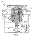
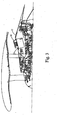
- Figures 1 and 2 show partially cut away side and front views, respectively, of a partially deployed air-oil heat exchanger, 10, mounted on a portion of an inner fan duct wall, 11, provided in a turbofan engine which is otherwise omitted from this figure, but which is shown in Figure 3 .
- a flange, 12 holds heat exchanger 10 against the inner engine core side of wall 11 so that the deployable portion of heat exchanger 10 can be deployed in the engine fan airstream through an opening, 13, in wall 11 that is on the opposite side of that wall from the engine core side thereof.
- Flange 12 is part of a metal container, 14, for heat exchanger 10 provided on the engine core side of wall 11.
- Bracket 15 located primarily on the airstream side of wall 11 and fastened to container 14 through opening 13 holds that container against wall 11.
- Bracket 15 has triangular shaped sidewalls across from one another with an opening therebetween to the interior of container 14 below that bracket on the upstream side of opening 13 on the left in Figure 1 , i.e. the front side of heat exchanger 10.
- Two further triangular shaped sidewalls are provided in bracket 15 across from one another with an opening therebetween to the interior of container 14 below on the downstream side of opening 13 on the right in Figure 1 .
- bracket 15 permit a portion of the fan airstream to enter into the interior of container 14 on the upstream side and to exit from container 14 on the downstream side thereof whenever the deployable portion of heat exchanger 10 is at least partly deployed in the engine fan airstream through an opening 13.
- the triangular shaped sidewalls on the upstream side help guide that portion of the airstream into the interior of container 14 whenever the deployable portion of heat exchanger 10 is at least partly deployed in the engine fan airstream by limiting to an extent airflow around that deployed portion of heat exchanger 10.
- the deployable portion of heat exchanger 10 is involves primarily a heat exchanger core, 20, having a substantial number of spaced apart passageway structures, 21, including air downstream passageway structures, 21', and air upstream passageway structures, 21", connected between two passageway end members including a lower passageway end member, 22, and an upper passageway end member, 23, held together by a frame, 24, so as to have access to the open interiors of these passageway structures from the open interiors of corresponding channels in the passageway end members.
- air downstream passageway structures 21' at the upper ends thereof in the figures, are joined to the open interiors of air upstream passageway structures 21", at the upper ends thereof in the figures, by appropriate channels provided in upper passageway end member 23 so that the working fluid, or oil, passing through air downstream passageway structures 21' can next pass through air upstream passageway structures 21".
- air downstream passageway structures 21' at the opposite, lower ends thereof are joined to the open interior of core oil inlet connector stub, 25, by channels in lower passageway end member 22.
- the open interiors of air upstream passageway structures 21" at the opposite, lower ends thereof are joined to the open interior of core oil outlet connector stub, 26, as seen in Figure 2 , by other channels in lower passageway end member 22.
- Oil will enter heat exchanger core 20 through core oil inlet connector stub 25 to pass lower passageway end member 22 as shown by the bolded block arrow pointing to the left in Figure 1 therefrom at the bottom of core 20.
- Connections to air downstream passageway structures 21' results in the oil at the greatest temperatures then passing first through air downstream passageway structures 21' in core heat exchanger 20 to be cooled and then reach upper passageway end member 23 as shown by the bolded block arrows on the right pointing upward, and then the two pointing leftward at the top of the core, in Figure 1 .
- This oil then next passes through air upstream passageway structures 21" connected to upper passageway end member 23 to be further cooled as shown by the bolded block arrows on the left pointing downward, to reach lower passageway end member 22.
- the cooled oil then exits heat exchanger core 20 via core oil outlet connector stub 26, seen only in Figure 2 , as shown by the bolded block arrows pointing to the right in Figure 1 at the bottom of core 20.
- Such oil or working fluid is returned to such systems from heat exchanger 10 through an exchanger oil outlet connector stub, 28, also mounted on frame 14 of heat exchanger 10 as seen in Figure 2 .
- FIG. 1 and 2 One arrangement for connecting exchanger oil inlet connector stub 27 on frame 14 to core oil inlet connector stub 25 on heat exchanger core 20 is shown in Figures 1 and 2 using two tube or hose sections, 29 and 30, which are joined to one another by a swivel coupling, 31.
- Section 29 is joined with core oil inlet connector stub 25 by another swivel coupling, 32
- section 30 is joined with exchanger oil inlet connector stub 27 by a further swivel coupling, 33.
- These swivel couplings each have two sections both having an outer wall about an open space within open to that of the other, and with these sections being connected to each other so as to allow them to rotate with respect to one another.
- Each of these sections has a corresponding fitting providing an opening therethrough to the space within that allows each section to be connected to a corresponding external conduit for transferring fluid to and from the interior space thereof.
- FIG. 1 and 2 an arrangement for connecting exchanger oil outlet connector stub 28 on the same side of container 14 to core oil outlet connector stub 26 on heat exchanger core 20 is shown in Figures 1 and 2 also uses two tube or hose sections, 34 and 35, which are joined to one another by a swivel coupling, 36.
- Section 34 is joined with core oil outlet connector stub 26 by another swivel coupling, 37
- section 35 is joined with exchanger oil outlet connector stub 28 by yet another swivel coupling, 38.
- the two tube or hose sections with swivel couplings could have flexible hoses and clamped slip-on couplings substituted therefor, or some other flexible conduit arrangement could alternatively be used.
- Heat exchanger core 20 can be selectively deployed in selected frontal area fraction thereof for a turbofan engine in the engine fan airstream above wall 11, in the figures, using alternatively an electrical, hydraulic or pneumatic motor, 40, (an electric motor being shown in Figures 1 and 2 ) to raise a platform upon which core 20 is mounted or, as alternatively shown in Figures 1 and 2 , to rotate threaded jackscrews, 41 and 42, engaged with threaded nuts, 43 and 44, mounted directly across from one another on the opposite sides of core frame 24.
- an electrical, hydraulic or pneumatic motor 40, (an electric motor being shown in Figures 1 and 2 ) to raise a platform upon which core 20 is mounted or, as alternatively shown in Figures 1 and 2 , to rotate threaded jackscrews, 41 and 42, engaged with threaded nuts, 43 and 44, mounted directly across from one another on the opposite sides of core frame 24.
- a gearbox, 45 has one end of the rotor shaft (unseen in the figures) of motor 40 extending therein to engage suitable gearing (unseen in the figures) to rotate jackscrew 41 in response to the rotation of that rotor shaft within attached core frame nut 43.
- a gearbox, 46 has the other end of the rotor shaft (unseen in the figures) of motor 40 extending therein to engage suitable gearing (unseen in the figures) to rotate jackscrew 42 in response to the rotation of that rotor shaft within attached core frame nut 44.
- rotation of the motor rotor shaft in one direction results in raising heat exchanger core 20 toward and into the fan engine airstream above wall 11 in the figures a selected distance depending on the amount of shaft rotation.
- rotation of that shaft in the opposite direction results in lowering core 20 toward and back into the fan engine compartment a selected distance again depending on the amount of shaft rotation in this opposite direction.
- the electrical power to cause selected rotations of the rotor shaft of motor 40 is selectively supplied to an electrical connector, 47, mounted on the side of container 14 to which an electrical wiring cable, 48, extending from motor 40, is connected.
- a core cover, 50 formed of materials similar to that used in providing wall 11, is provided affixed to the top of core frame 24 to achieve this degree of sealing.
- the outer surface of core cover 50 is shaped to be flush with, and to conform to the curvatures and contours of, the adjacent surface contours of wall 11:
- the outer surface of the engine compartment, with heat exchanger 10 mounted within this compartment is presented to the engine fan airstream as a smooth surface when core 20 is fully retracted into container 14 except for the narrow edges of the triangular shaped sidewalls of bracket 15 facing the airstream.
- This configuration with core 20 being fully retracted thereby minimizes any airstream disturbance in conditions in which heat exchanger 10 is not being used to cool oil flowing through it from exchanger oil inlet connector stub 27 to exchanger oil outlet connector stub 28.
- the upstream side of core cover 50 has a sculpted front to form a front inner surface, 51, facing the engine fan airstream when core 20 is deployed to some extent in that airstream.
- Front inner surface 51 follows the contour of the outer surface of core cover 50 extending right and left as seen in Figure 2 , and begins at the upstream front edge of core cover 50 paralleling that outer surface thereof but then curves downward toward the engine compartment as seen in Figure 1 .
- Such a downward curving front inner surface directs a portion of the engine fan airstream downward through the upstream opening in bracket 15 into container 14 so that part of it passes more or less straight through the part of core 20 directly exposed to this airstream when that core is deployed to some extent therein.
- passageway structures 21 in heat exchanger core 20 are subjected to the diverted airstream portion in varying degree to cool the oil flowing through those passageways upon any deployment of that core in the airstream, and not just the.core part directly exposed to that airstream because of the deployment.
- the diverted airstream portion is further confined to pass through the entirety of passageway structures 21 in heat exchanger core 20 by, first, a baffle, 52, seen Figure 1 that is attached to the bottom of heat exchanger core 20 and extends outward therefrom toward the upstream direction.
- Baffle 52 substantially closes off the portion of the interior volume of container 14 (across from air upstream passageway structures 21", between those structures and the facing wall of that container) from the volume of container 14 below core 20 on the upstream side of that container at whatever degree of deployment of core 20 has occurred.
- a pair of sidewalls, 53 and 54, mounted in container 14 on either side of heat exchanger core 20 substantially closes the sides of that same interior volume across from air upstream passageway structures 21" so that the incoming diverted portion of the engine fan airstream is substantially directed toward air upstream passageway structures 21".
- maximum cooling of the oil flowing in these structures is obtained from the diverted airstream portion substantially confined by baffle 52 and sidewalls 53 and 54 to pass by these structures.
- heat exchanger 10 will be provided in fluid operated equipment system, such as the lubrication system for a turbofan engine, that is supplemented by an electrical control system directing operations of that equipment system and its components. Often, this will involve a feedback control loop using a temperature sensor to measure the temperature of the working fluid, such as oil in a lubrication system, and the sensor signal will be used by the controller in the control loop to control the cooling of that working fluid.
- a control loop can be used to selectively direct electrical power to electrical connector 47 of heat exchanger 10, and so to motor 40 therein, to control the extent of deployment of heat exchanger core 20 into the engine fan airstream to control the rate of cooling of the oil flowing through passageway structures 21 in that core.
Landscapes
- Engineering & Computer Science (AREA)
- Mechanical Engineering (AREA)
- General Engineering & Computer Science (AREA)
- Chemical & Material Sciences (AREA)
- Combustion & Propulsion (AREA)
- Physics & Mathematics (AREA)
- Thermal Sciences (AREA)
- Heat-Exchange Devices With Radiators And Conduit Assemblies (AREA)
Claims (19)
- Système échangeur de chaleur (10) destiné à être utilisé dans des systèmes de lubrification pour un équipement de turboréacteur à double flux d'aéronef utilisant un fluide de travail pour le doter de modes de fonctionnement sélectionnés, le système échangeur de chaleur servant à réaliser des échanges de chaleur entre de l'air et le fluide de travail pour refroidir le fluide de travail à des vitesses sélectivement variables dans des filets d'air présents d'un côté filets d'une paroi (11) procurée avec l'équipement, le système comprenant :un actionneur (40) monté de manière à se trouver sensiblement d'un côté de la paroi (11) opposé au côté filets et contenant un effecteur de mouvement positionnable mobile pour prendre des positions sélectionnées par rapport à une ouverture (13) dans la paroi (11) ; etun faisceau (20) d'échangeur de chaleur contenant une pluralité de structures formant passage (21) autour desquelles l'air peut s'écouler en les traversant, les structures formant passage (21) étant reliées, à une extrémité, à un conduit d'entrée et, à une extrémité opposée, à un conduit de sortie pour permettre d'amener le fluide de travail à l'intérieur des structures formant passage (21) et de l'évacuer de celles-ci par l'intérieur des conduits d'entrée et de sortie, le faisceau (20) d'échangeur de chaleur étant monté sur l'effecteur de mouvement de manière à pouvoir être déployé par celui-ci à travers l'ouverture (13) sur des distances sélectionnées jusque dans la région destinée à être occupée par les filets d'air du côté filets de la paroi (11) et à pouvoir être sélectivement escamoté depuis ces distances.
- Système selon la revendication 1, le faisceau (20) d'échangeur de chaleur étant en outre coiffé d'une structure d'obturation (50), le faisceau (20) d'échangeur de chaleur se trouvant en dehors de la région destinée à être occupée par les filets d'air si le faisceau (20) d'échangeur de chaleur occupe une position non déployée, la structure d'obturation (50) bloquant alors sensiblement l'ouverture (13), et se trouvant au moins partiellement dans la région destinée à être occupée par les filets d'air si le faisceau (20) d'échangeur de chaleur occupe une position déployée.
- Système selon la revendication 2, comprenant en outre un contenant (14) à l'intérieur duquel l'actionneur (40) et le faisceau (20) d'échangeur de chaleur sont reçus au moins partiellement, l'intérieur du contenant (14) étant sensiblement obturé vis-à-vis de la région destinée à être occupée par les filets d'air si le faisceau (20) d'échangeur de chaleur occupe une position non déployée du fait que la structure d'obturation (50) sur le faisceau (20) d'échangeur de chaleur bloque sensiblement l'ouverture (13) de façon à ce qu'une surface extérieure de celle-ci affleure des parties adjacentes de la surface de la paroi (11) située du côté filets de celle-ci et en épouse les contours.
- Système selon la revendication 3, comprenant en outre une admission (27) de contenant et une évacuation (28) de contenant ménagées à travers un côté du contenant (14), et une admission (25) de faisceau et une évacuation (26) de faisceau ménagées sur le faisceau (20) d'échangeur de chaleur entre lesquelles
sont raccordées les structures formant passage (21) à intérieurs ouverts dans le faisceau (20) d'échangeur de chaleur, l'admission (27) de contenant et l'admission (25) de faisceau étant reliées par un conduit flexible (29, 30), l'évacuation (28) de contenant et l'évacuation (26) de faisceau étant aussi reliées par un autre conduit flexible (34, 35) de manière à faire passer le fluide de travail par l'admission (27) de contenant et à lui faire traverser l'admission (25) de faisceau, les structures formant passage (21) à intérieurs ouverts, l'évacuation (26) de faisceau et l'évacuation (28) de contenant, les conduits flexibles (29, 30 ; 34, 35) fléchissant suffisamment pour rester ainsi reliés suite à des déploiements et à des escamotages du faisceau (20) d'échangeur de chaleur. - Système selon la revendication 3 ou 4, comprenant en outre une paire de parois latérales (53, 54) montées dans le contenant (14) sensiblement perpendiculairement à la paroi (11) et s'étendant suivant des côtés opposés du faisceau (20) d'échangeur de chaleur sensiblement parallèlement à la direction principalement suivie par les filets d'air dans la région destinée à être occupée par ceux-ci.
- Système selon la revendication 3, 4 ou 5, comprenant en outre une chicane (52) à l'intérieur du contenant reliée au faisceau (20) d'échangeur de chaleur d'un côté de celui-ci opposé à la structure d'obturation (50) et s'étendant pratiquement jusqu'à un côté du contenant dans une direction opposée à la direction principalement suivie par les filets d'air dans la région destinée à être occupée par ceux-ci de manière à ce que la chicane (52) isole sensiblement de façon étanche la partie de l'intérieur d'un côté du faisceau (20) d'échangeur de chaleur de la partie de l'intérieur d'un côté opposé de la chicane (52).
- Système selon l'une quelconque des revendications 3 à 6, la structure d'obturation (50) possédant une extrémité tournée vers une direction opposée à la direction principalement suivie par les filets d'air dans la région destinée à être occupée par ceux-ci, laquelle extrémité présente une surface qui y trouve son origine sensiblement parallèle à la paroi (11) et présentant une convexité suffisante vers l'intérieur de l'extrémité pour s'orienter sensiblement perpendiculairement à la paroi (11).
- Système selon la revendication 2, comprenant en outre une paire de parois latérales (53, 54) sensiblement perpendiculaires à la paroi (11) et s'étendant suivant des côtés opposés du faisceau (20) d'échangeur de chaleur sensiblement parallèlement à la direction principalement suivie par les filets d'air dans la région destinée à être occupée par ceux-ci.
- Système selon la revendication 2 ou 8, comprenant en outre une chicane (52) reliée au faisceau (20) d'échangeur de chaleur d'un côté de celui-ci opposé à la structure d'obturation (50) et s'étendant dans une direction opposée à la direction principalement suivie par les filets d'air dans la région destinée à être occupée par ceux-ci de manière à ce que la chicane (52) isole sensiblement de façon étanche la partie de l'intérieur d'un côté du faisceau (20) d'échangeur de chaleur de la partie de l'intérieur d'un côté opposé de la chicane (52).
- Système selon l'une quelconque des revendications précédentes, l'actionneur comprenant un moteur (40) entraînant en rotation un vérin à vis (41, 42) à l'intérieur d'un écrou fileté (43, 44) fixé à un côté du faisceau (20) d'échangeur de chaleur.
- Système selon l'une quelconque des revendications précédentes, des parties d'entrée de la
pluralité de structures formant passage (21) étant reliées, à une extrémité, à un conduit d'entrée et des parties de sortie de la pluralité de structures formant passage (21) étant reliées, à une extrémité, à un conduit de sortie, les parties d'entrée et les parties de sortie de la pluralité de structures formant passage (21) étant reliées, à des extrémités opposées, à des parties correspondant les unes aux autres. - Système selon la revendication 1, le fluide de travail étant un lubrifiant amené sous pression dans des espaces délimités au moins partiellement par des surfaces mobiles les unes par rapport aux autres, et la paroi étant une paroi (11) de canalisation de soufflante de réacteur,
l'actionneur étant un moteur (40) apte à être commandé possédant un arbre doté d'une position angulaire sélectionnable, l'effecteur de mouvement positionnable étant relié à l'arbre et mobile pour prendre des positions sélectionnées par rapport à une ouverture (13) dans la paroi (11) grâce à des rotations sélectionnées de l'arbre ;
le faisceau (20) d'échangeur de chaleur étant coiffé d'une structure d'obturation (50) contenant la pluralité de structures formant passage (21) ; et
le faisceau (20) d'échangeur de chaleur étant sélectivement escamotable de manière à s'escamoter suffisamment hors de la région destinée à être occupée par les filets d'air si le faisceau (20) d'échangeur de chaleur occupe une position non déployée de sorte que la structure d'obturation (50) sur le faisceau (20) d'échangeur de chaleur bloque sensiblement l'ouverture (13). - Système selon la revendication 12, la structure d'obturation (50) sur le faisceau d'échangeur de chaleur bloquant sensiblement l'ouverture (13) de façon à ce qu'une surface extérieure de celle-ci affleure des
parties adjacentes de la surface de la paroi (11) située du côté filets et en épouse les contours. - Système selon la revendication 12 ou 13, comprenant en outre un contenant (14) à l'intérieur duquel le moteur (40) et le faisceau (20) d'échangeur de chaleur sont reçus au moins partiellement, une paire de parois latérales (53, 54) étant montées dans le contenant (14) sensiblement perpendiculairement à la paroi (11) et s'étendant suivant des côtés opposés du faisceau (20) d'échangeur de chaleur sensiblement parallèlement à la direction principalement suivie par les filets d'air dans la région destinée à être occupée par ceux-ci.
- Système selon la revendication 12 ou 13, comprenant en outre un contenant (14) à l'intérieur duquel le moteur (40) et le faisceau (20) d'échangeur de chaleur sont reçus au moins partiellement, une chicane (52) montée à l'intérieur du contenant (14) étant reliée au faisceau (20) d'échangeur de chaleur d'un côté de celui-ci opposé à la structure d'obturation (50) et s'étendant pratiquement jusqu'à un côté du contenant (14) dans une direction opposée à la direction principalement suivie par les filets d'air dans la région destinée à être occupée par ceux-ci de manière à ce que la chicane (52) isole sensiblement de façon étanche la partie de l'intérieur d'un côté du faisceau (20) d'échangeur de chaleur de la partie de l'intérieur d'un côté opposé de la chicane (52).
- Système selon l'une quelconque des revendications 12 à 15, la structure d'obturation (50) possédant une extrémité tournée vers une direction opposée à la direction principalement suivie par les filets d'air dans la région destinée à être occupée par ceux-ci, laquelle extrémité présente une surface qui y trouve son origine sensiblement parallèle à la paroi et présentant une convexité suffisante vers l'intérieur de l'extrémité pour s'orienter sensiblement perpendiculairement à la paroi (11).
- Système selon la revendication 1, le fluide de travail étant un lubrifiant amené sous pression dans des espaces délimités au moins partiellement par des surfaces mobiles les unes par rapport aux autres, et la paroi étant une paroi (11) de canalisation de soufflante de réacteur,
l'actionneur étant un moteur (40) apte à être commandé possédant un arbre doté d'une position angulaire sélectionnable, l'effecteur de mouvement positionnable étant relié à l'arbre et mobile pour prendre des positions sélectionnées par rapport à une ouverture (13) dans la paroi (11) grâce à des rotations sélectionnées de l'arbre ;
le système comprenant en outre :un contenant (14) monté sur la paroi (11) autour de l'ouverture (13), à l'intérieur duquel le moteur (40) et le faisceau (20) d'échangeur de chaleur sont reçus au moins partiellement. - Système selon la revendication 17, le faisceau (20) d'échangeur de chaleur étant en outre doté d'une structure d'obturation (50), l'intérieur du contenant (14) étant sensiblement obturé vis-à-vis de la région destinée à être occupée par les filets d'air si le faisceau (20) d'échangeur de chaleur occupe une position non déployée du fait que la structure d'obturation (50) sur le faisceau (20) d'échangeur de chaleur bloque sensiblement l'ouverture (13) de façon à ce qu'une surface extérieure de celle-ci affleure des parties adjacentes de la surface de la paroi (11) située du côté filets de celle-ci et en épouse les contours.
- Système selon la revendication 17 ou 18, comprenant en outre une admission (27) de contenant et une évacuation (28) de contenant ménagées à travers un côté du contenant (14), et une admission (25) de faisceau et une évacuation (26) de faisceau ménagées sur le faisceau (20) d'échangeur de chaleur entre lesquelles sont raccordées les structures formant passage (21) à intérieurs ouverts dans le faisceau (20) d'échangeur de chaleur, l'admission (27) de contenant et l'admission (25) de faisceau étant reliées par un conduit flexible (29, 30), l'évacuation (28) de contenant et l'évacuation (26) de faisceau étant aussi reliées par un autre conduit flexible (34, 35) de manière à faire passer le lubrifiant par l'admission (27) de contenant et à lui faire traverser l'admission (25) de faisceau, les structures formant passage (21) à intérieurs ouverts, l'évacuation (26) de faisceau et l'évacuation (28) de contenant, les conduits flexibles fléchissant suffisamment pour rester ainsi reliés suite à des déploiements et à des escamotages du faisceau (20) d'échangeur de chaleur.
Applications Claiming Priority (1)
| Application Number | Priority Date | Filing Date | Title |
|---|---|---|---|
| US11/378,166 US8127828B2 (en) | 2006-03-17 | 2006-03-17 | Air-oil heat exchanger |
Publications (3)
| Publication Number | Publication Date |
|---|---|
| EP1835128A2 EP1835128A2 (fr) | 2007-09-19 |
| EP1835128A3 EP1835128A3 (fr) | 2011-02-09 |
| EP1835128B1 true EP1835128B1 (fr) | 2012-04-25 |
Family
ID=38180179
Family Applications (1)
| Application Number | Title | Priority Date | Filing Date |
|---|---|---|---|
| EP07250975A Expired - Fee Related EP1835128B1 (fr) | 2006-03-17 | 2007-03-08 | Échangeur thermique escamotable pour un système de lubrification d'un turboréacteur à double flux |
Country Status (3)
| Country | Link |
|---|---|
| US (2) | US8127828B2 (fr) |
| EP (1) | EP1835128B1 (fr) |
| JP (1) | JP5220330B2 (fr) |
Families Citing this family (35)
| Publication number | Priority date | Publication date | Assignee | Title |
|---|---|---|---|---|
| US8127828B2 (en) * | 2006-03-17 | 2012-03-06 | United Technologies Corporation | Air-oil heat exchanger |
| US8776952B2 (en) * | 2006-05-11 | 2014-07-15 | United Technologies Corporation | Thermal management system for turbofan engines |
| US8627667B2 (en) * | 2008-12-29 | 2014-01-14 | Roll-Royce Corporation | Gas turbine engine duct having a coupled fluid volume |
| WO2011050823A1 (fr) | 2009-10-28 | 2011-05-05 | Powerwind Gmbh | Dispositif de refroidissement rabattable |
| EP2325482B1 (fr) | 2009-11-24 | 2014-01-01 | Siemens Aktiengesellschaft | Agencement avec nacelle et radiateur |
| EP2325485B1 (fr) * | 2009-11-24 | 2012-08-29 | Siemens Aktiengesellschaft | Agencement d'une nacelle avec un radiateur rentrant |
| DK2325483T3 (da) | 2009-11-24 | 2012-11-19 | Siemens Ag | Indretning med en modulær nacelle med en udstråler |
| EP2336525B1 (fr) * | 2009-12-21 | 2015-08-26 | Techspace Aero S.A. | Intégration d'un échangeur de chaleur air-liquide sur moteur |
| GB201001410D0 (en) * | 2010-01-29 | 2010-03-17 | Rolls Royce Plc | Oil cooler |
| FR2957053B1 (fr) * | 2010-03-03 | 2016-09-09 | Aircelle Sa | Ensemble de refroidissement pour un composant d'une nacelle pour turboreacteur |
| WO2012012912A1 (fr) * | 2010-07-29 | 2012-02-02 | General Electric Company | Système de transfert thermique transformable pour entrée de turbine à gaz |
| US8522521B2 (en) | 2010-11-09 | 2013-09-03 | Hamilton Sundstrand Corporation | Combined air turbine starter, air-oil cooler, and fan |
| US8876476B2 (en) | 2010-11-16 | 2014-11-04 | Hamilton Sundstrand Corporation | Integrated accessory gearbox and engine starter |
| US8961114B2 (en) * | 2010-11-22 | 2015-02-24 | General Electric Company | Integrated variable geometry flow restrictor and heat exchanger |
| US20120308369A1 (en) * | 2011-05-31 | 2012-12-06 | Mra Systems, Inc. | Laminate thermal insulation blanket for aircraft applications and process therefor |
| US9260191B2 (en) * | 2011-08-26 | 2016-02-16 | Hs Marston Aerospace Ltd. | Heat exhanger apparatus including heat transfer surfaces |
| EP2626533A1 (fr) * | 2012-02-07 | 2013-08-14 | Siemens Aktiengesellschaft | Procédé destiné au fonctionnement d'une turbine à gaz |
| US9267390B2 (en) | 2012-03-22 | 2016-02-23 | Honeywell International Inc. | Bi-metallic actuator for selectively controlling air flow between plena in a gas turbine engine |
| US9599410B2 (en) | 2012-07-27 | 2017-03-21 | General Electric Company | Plate-like air-cooled engine surface cooler with fluid channel and varying fin geometry |
| US20140216056A1 (en) | 2012-09-28 | 2014-08-07 | United Technologies Corporation | Heat exchange module for a turbine engine |
| US9945325B2 (en) * | 2013-02-20 | 2018-04-17 | United Technologies Corporation | Integrated heat exchangers for low fan pressure ratio geared turbofan |
| EP2971672B1 (fr) * | 2013-03-15 | 2018-09-26 | United Technologies Corporation | Moteur à turbine à gaz doté d'un réservoir d'huile à refroidisseur air-huile |
| DE102013110117A1 (de) * | 2013-09-13 | 2015-04-02 | Jess Gmbh Energiespeichersysteme | Hochtemperaturwärmespeicher |
| US10697371B2 (en) | 2015-12-28 | 2020-06-30 | General Electric Company | Method and system for a combined air-oil cooler and fuel-oil cooler heat exchanger |
| US20170307311A1 (en) * | 2016-04-26 | 2017-10-26 | United Technologies Corporation | Simple Heat Exchanger Using Super Alloy Materials for Challenging Applications |
| US10337408B2 (en) * | 2016-06-08 | 2019-07-02 | Mra Systems, Llc | Thermal insulation blanket and thermal insulation blanket assembly |
| US10676205B2 (en) * | 2016-08-19 | 2020-06-09 | General Electric Company | Propulsion engine for an aircraft |
| JP6838794B2 (ja) * | 2016-09-08 | 2021-03-03 | ユニゾン・インダストリーズ,エルエルシー | 冷却器を有するファンケーシング組立体 |
| US10634049B2 (en) | 2017-01-16 | 2020-04-28 | Pratt & Whitney Canada Corp. | Turbofan engine assembly with intercooler |
| US10450952B2 (en) | 2017-01-16 | 2019-10-22 | Pratt & Whitney Canada Corp. | Turbofan engine assembly with gearbox |
| FR3089248B1 (fr) * | 2018-12-03 | 2020-11-20 | Safran Aircraft Engines | Ensemble moteur pour aéronef présentant un support de système d’échangeur air-huile a fixation optimisée |
| BE1027057B1 (fr) * | 2019-02-18 | 2020-09-14 | Safran Aero Boosters Sa | Échangeur de chaleur air-huile |
| GB2589125B (en) * | 2019-11-21 | 2022-10-19 | Gkn Aerospace Sweden Ab | Heat exchanger integration |
| FR3108682B1 (fr) * | 2020-03-30 | 2022-12-09 | Safran Aircraft Engines | Echangeur de chaleur air-huile rétractable pour ensemble propulsif d’aéronef |
| CN112412714A (zh) * | 2020-11-26 | 2021-02-26 | 明阳智慧能源集团股份公司 | 一种风力发电机组活动式自然风冷散热系统 |
Family Cites Families (26)
| Publication number | Priority date | Publication date | Assignee | Title |
|---|---|---|---|---|
| US1374610A (en) * | 1920-02-28 | 1921-04-12 | Jean Jules Marie Antoin Schnei | Apparatus for regulating the effective surface of the radiators of aeroplane-engines |
| US1549202A (en) * | 1922-02-14 | 1925-08-11 | Dayton Wright Company | Retractable radiator |
| US1807514A (en) * | 1928-06-29 | 1931-05-26 | Dewoitine Julien Eugene Emile | Radiator actuating mechanism |
| US1836592A (en) * | 1930-03-31 | 1931-12-15 | Wilbur A Hammond | Airplane |
| US2249948A (en) * | 1937-12-15 | 1941-07-22 | Dornier Werke Gmbh | Cooler plant for aircraft |
| US2147283A (en) * | 1938-01-19 | 1939-02-14 | Hart & Cooley Mfg Company | Heating device |
| US2291607A (en) * | 1938-12-24 | 1942-08-04 | Chausson Usines Sa | Cooling device for engines |
| US2295115A (en) * | 1939-10-21 | 1942-09-08 | Elizabeth B Keller | Retractable water heater |
| US2305897A (en) * | 1940-09-14 | 1942-12-22 | Briggs Mfg Co | Transmission mechanism |
| US3804353A (en) * | 1972-08-28 | 1974-04-16 | Piper Aircraft Corp | Condenser installation for aircraft air-conditioning system |
| US4151710A (en) * | 1977-03-11 | 1979-05-01 | United Technologies Corporation | Lubrication cooling system for aircraft engine accessory |
| US4474001A (en) * | 1981-04-01 | 1984-10-02 | United Technologies Corporation | Cooling system for the electrical generator of a turbofan gas turbine engine |
| JPS5851028U (ja) * | 1981-10-01 | 1983-04-06 | 石川島播磨重工業株式会社 | 航空用ガス・タ−ビン・エンジンの潤滑油空冷装置 |
| US5123242A (en) | 1990-07-30 | 1992-06-23 | General Electric Company | Precooling heat exchange arrangement integral with mounting structure fairing of gas turbine engine |
| US5082049A (en) * | 1990-11-13 | 1992-01-21 | Robert R. Pisano | Heat generator for use with an absorption airconditioning system for automobiles |
| US5269135A (en) | 1991-10-28 | 1993-12-14 | General Electric Company | Gas turbine engine fan cooled heat exchanger |
| FR2734319B1 (fr) * | 1995-05-15 | 1997-07-18 | Aerospatiale | Dispositif pour prelever et refroidir de l'air chaud au niveau d'un moteur d'aeronef |
| JPH10121127A (ja) * | 1996-10-09 | 1998-05-12 | Chugai Ro Co Ltd | 二室間移動式ガスクーラ |
| US6058696A (en) * | 1997-12-22 | 2000-05-09 | United Technologies Corporation | Inlet and outlet module for a heat exchanger for a flowpath for working medium gases |
| US6106229A (en) * | 1997-12-22 | 2000-08-22 | United Technologies Corporation | Heat exchanger system for a gas turbine engine |
| US6587862B1 (en) | 1999-09-07 | 2003-07-01 | Spectral Logic Design | Apparatus and method for direct digital frequency synthesis |
| FR2839948B1 (fr) * | 2002-05-22 | 2004-12-17 | Airbus France | Echangeur pour circuit de conditionnement d'air d'aeronef et ensemble de propulsion integrant un tel echangeur |
| US8127828B2 (en) * | 2006-03-17 | 2012-03-06 | United Technologies Corporation | Air-oil heat exchanger |
| US7765788B2 (en) * | 2006-07-06 | 2010-08-03 | United Technologies Corporation | Cooling exchanger duct |
| US7861512B2 (en) * | 2006-08-29 | 2011-01-04 | Pratt & Whitney Canada Corp. | Turbofan bypass duct air cooled fluid cooler installation |
| EP1944475B1 (fr) * | 2007-01-08 | 2015-08-12 | United Technologies Corporation | Système d'échange de chaleur |
-
2006
- 2006-03-17 US US11/378,166 patent/US8127828B2/en not_active Expired - Fee Related
-
2007
- 2007-03-08 EP EP07250975A patent/EP1835128B1/fr not_active Expired - Fee Related
- 2007-03-19 JP JP2007069990A patent/JP5220330B2/ja not_active Expired - Fee Related
-
2011
- 2011-11-21 US US13/301,100 patent/US8534043B2/en not_active Expired - Fee Related
Also Published As
| Publication number | Publication date |
|---|---|
| JP2007247651A (ja) | 2007-09-27 |
| US20070215326A1 (en) | 2007-09-20 |
| US8534043B2 (en) | 2013-09-17 |
| JP5220330B2 (ja) | 2013-06-26 |
| US8127828B2 (en) | 2012-03-06 |
| EP1835128A3 (fr) | 2011-02-09 |
| EP1835128A2 (fr) | 2007-09-19 |
| US20120060466A1 (en) | 2012-03-15 |
Similar Documents
| Publication | Publication Date | Title |
|---|---|---|
| EP1835128B1 (fr) | Échangeur thermique escamotable pour un système de lubrification d'un turboréacteur à double flux | |
| US7765788B2 (en) | Cooling exchanger duct | |
| EP1944475B1 (fr) | Système d'échange de chaleur | |
| EP1882824B1 (fr) | Tuyau d'admission double d'échangeur de refroidissement de lubrifiant | |
| EP1857638B1 (fr) | Système de gestion thermique pour moteurs de réacteur à double flux | |
| EP1930557B1 (fr) | Moteur de turbine doté d'un générateur intégré avec système de lubrification partagé | |
| EP1923542B1 (fr) | Systèmes de lubrification interdépendants | |
| US11708794B2 (en) | Gearbox efficiency rating for turbomachine engines | |
| EP2971664B2 (fr) | Moteur à turbosoufflante à engrenage et son procédé de refroidissement | |
| CN114060474A (zh) | 涡轮机发动机的齿轮箱效率等级 | |
| EP3483414B1 (fr) | Moteur à turbine à gaz doté d'un échangeur de chaleur air-huile | |
| US10036322B2 (en) | Electroformed nickel-chromium alloy | |
| JP2015101264A (ja) | 航空機 | |
| CN117125258A (zh) | 飞机辅助动力装置系统 | |
| US20110182723A1 (en) | Turbomachine aircraft propeller |
Legal Events
| Date | Code | Title | Description |
|---|---|---|---|
| PUAI | Public reference made under article 153(3) epc to a published international application that has entered the european phase |
Free format text: ORIGINAL CODE: 0009012 |
|
| AK | Designated contracting states |
Kind code of ref document: A2 Designated state(s): AT BE BG CH CY CZ DE DK EE ES FI FR GB GR HU IE IS IT LI LT LU LV MC MT NL PL PT RO SE SI SK TR |
|
| AX | Request for extension of the european patent |
Extension state: AL BA HR MK YU |
|
| PUAL | Search report despatched |
Free format text: ORIGINAL CODE: 0009013 |
|
| AK | Designated contracting states |
Kind code of ref document: A3 Designated state(s): AT BE BG CH CY CZ DE DK EE ES FI FR GB GR HU IE IS IT LI LT LU LV MC MT NL PL PT RO SE SI SK TR |
|
| AX | Request for extension of the european patent |
Extension state: AL BA HR MK RS |
|
| 17P | Request for examination filed |
Effective date: 20110722 |
|
| GRAP | Despatch of communication of intention to grant a patent |
Free format text: ORIGINAL CODE: EPIDOSNIGR1 |
|
| RTI1 | Title (correction) |
Free format text: RETRACTABLE HEAT EXCHANGER FOR A LUBRICATION SYSTEM OF AN AIRCRAFT TURBOFAN ENGINE. |
|
| AKX | Designation fees paid |
Designated state(s): DE GB |
|
| RTI1 | Title (correction) |
Free format text: RETRACTABLE HEAT EXCHANGER FOR A LUBRICATION SYSTEM OF AN AIRCRAFT TURBOFAN ENGINE |
|
| GRAS | Grant fee paid |
Free format text: ORIGINAL CODE: EPIDOSNIGR3 |
|
| GRAA | (expected) grant |
Free format text: ORIGINAL CODE: 0009210 |
|
| AK | Designated contracting states |
Kind code of ref document: B1 Designated state(s): DE GB |
|
| REG | Reference to a national code |
Ref country code: GB Ref legal event code: FG4D |
|
| REG | Reference to a national code |
Ref country code: DE Ref legal event code: R096 Ref document number: 602007022220 Country of ref document: DE Effective date: 20120621 |
|
| PLBE | No opposition filed within time limit |
Free format text: ORIGINAL CODE: 0009261 |
|
| STAA | Information on the status of an ep patent application or granted ep patent |
Free format text: STATUS: NO OPPOSITION FILED WITHIN TIME LIMIT |
|
| 26N | No opposition filed |
Effective date: 20130128 |
|
| REG | Reference to a national code |
Ref country code: DE Ref legal event code: R097 Ref document number: 602007022220 Country of ref document: DE Effective date: 20130128 |
|
| PGFP | Annual fee paid to national office [announced via postgrant information from national office to epo] |
Ref country code: GB Payment date: 20140305 Year of fee payment: 8 |
|
| PGFP | Annual fee paid to national office [announced via postgrant information from national office to epo] |
Ref country code: DE Payment date: 20140417 Year of fee payment: 8 |
|
| REG | Reference to a national code |
Ref country code: DE Ref legal event code: R119 Ref document number: 602007022220 Country of ref document: DE |
|
| GBPC | Gb: european patent ceased through non-payment of renewal fee |
Effective date: 20150308 |
|
| PG25 | Lapsed in a contracting state [announced via postgrant information from national office to epo] |
Ref country code: GB Free format text: LAPSE BECAUSE OF NON-PAYMENT OF DUE FEES Effective date: 20150308 Ref country code: DE Free format text: LAPSE BECAUSE OF NON-PAYMENT OF DUE FEES Effective date: 20151001 |