EP1834855A1 - Running control device for vehicle - Google Patents
Running control device for vehicle Download PDFInfo
- Publication number
- EP1834855A1 EP1834855A1 EP06730540A EP06730540A EP1834855A1 EP 1834855 A1 EP1834855 A1 EP 1834855A1 EP 06730540 A EP06730540 A EP 06730540A EP 06730540 A EP06730540 A EP 06730540A EP 1834855 A1 EP1834855 A1 EP 1834855A1
- Authority
- EP
- European Patent Office
- Prior art keywords
- target acceleration
- curve
- target
- acceleration
- vehicle
- Prior art date
- Legal status (The legal status is an assumption and is not a legal conclusion. Google has not performed a legal analysis and makes no representation as to the accuracy of the status listed.)
- Granted
Links
Images




Classifications
-
- B—PERFORMING OPERATIONS; TRANSPORTING
- B60—VEHICLES IN GENERAL
- B60K—ARRANGEMENT OR MOUNTING OF PROPULSION UNITS OR OF TRANSMISSIONS IN VEHICLES; ARRANGEMENT OR MOUNTING OF PLURAL DIVERSE PRIME-MOVERS IN VEHICLES; AUXILIARY DRIVES FOR VEHICLES; INSTRUMENTATION OR DASHBOARDS FOR VEHICLES; ARRANGEMENTS IN CONNECTION WITH COOLING, AIR INTAKE, GAS EXHAUST OR FUEL SUPPLY OF PROPULSION UNITS IN VEHICLES
- B60K31/00—Vehicle fittings, acting on a single sub-unit only, for automatically controlling vehicle speed, i.e. preventing speed from exceeding an arbitrarily established velocity or maintaining speed at a particular velocity, as selected by the vehicle operator
- B60K31/0066—Vehicle fittings, acting on a single sub-unit only, for automatically controlling vehicle speed, i.e. preventing speed from exceeding an arbitrarily established velocity or maintaining speed at a particular velocity, as selected by the vehicle operator responsive to vehicle path curvature
-
- B—PERFORMING OPERATIONS; TRANSPORTING
- B60—VEHICLES IN GENERAL
- B60T—VEHICLE BRAKE CONTROL SYSTEMS OR PARTS THEREOF; BRAKE CONTROL SYSTEMS OR PARTS THEREOF, IN GENERAL; ARRANGEMENT OF BRAKING ELEMENTS ON VEHICLES IN GENERAL; PORTABLE DEVICES FOR PREVENTING UNWANTED MOVEMENT OF VEHICLES; VEHICLE MODIFICATIONS TO FACILITATE COOLING OF BRAKES
- B60T7/00—Brake-action initiating means
- B60T7/12—Brake-action initiating means for automatic initiation; for initiation not subject to will of driver or passenger
- B60T7/22—Brake-action initiating means for automatic initiation; for initiation not subject to will of driver or passenger initiated by contact of vehicle, e.g. bumper, with an external object, e.g. another vehicle, or by means of contactless obstacle detectors mounted on the vehicle
-
- B—PERFORMING OPERATIONS; TRANSPORTING
- B60—VEHICLES IN GENERAL
- B60W—CONJOINT CONTROL OF VEHICLE SUB-UNITS OF DIFFERENT TYPE OR DIFFERENT FUNCTION; CONTROL SYSTEMS SPECIALLY ADAPTED FOR HYBRID VEHICLES; ROAD VEHICLE DRIVE CONTROL SYSTEMS FOR PURPOSES NOT RELATED TO THE CONTROL OF A PARTICULAR SUB-UNIT
- B60W30/00—Purposes of road vehicle drive control systems not related to the control of a particular sub-unit, e.g. of systems using conjoint control of vehicle sub-units
- B60W30/14—Adaptive cruise control
- B60W30/16—Control of distance between vehicles, e.g. keeping a distance to preceding vehicle
-
- B—PERFORMING OPERATIONS; TRANSPORTING
- B60—VEHICLES IN GENERAL
- B60W—CONJOINT CONTROL OF VEHICLE SUB-UNITS OF DIFFERENT TYPE OR DIFFERENT FUNCTION; CONTROL SYSTEMS SPECIALLY ADAPTED FOR HYBRID VEHICLES; ROAD VEHICLE DRIVE CONTROL SYSTEMS FOR PURPOSES NOT RELATED TO THE CONTROL OF A PARTICULAR SUB-UNIT
- B60W30/00—Purposes of road vehicle drive control systems not related to the control of a particular sub-unit, e.g. of systems using conjoint control of vehicle sub-units
- B60W30/18—Propelling the vehicle
- B60W30/18009—Propelling the vehicle related to particular drive situations
- B60W30/18145—Cornering
-
- B—PERFORMING OPERATIONS; TRANSPORTING
- B60—VEHICLES IN GENERAL
- B60T—VEHICLE BRAKE CONTROL SYSTEMS OR PARTS THEREOF; BRAKE CONTROL SYSTEMS OR PARTS THEREOF, IN GENERAL; ARRANGEMENT OF BRAKING ELEMENTS ON VEHICLES IN GENERAL; PORTABLE DEVICES FOR PREVENTING UNWANTED MOVEMENT OF VEHICLES; VEHICLE MODIFICATIONS TO FACILITATE COOLING OF BRAKES
- B60T2201/00—Particular use of vehicle brake systems; Special systems using also the brakes; Special software modules within the brake system controller
- B60T2201/02—Active or adaptive cruise control system; Distance control
-
- B—PERFORMING OPERATIONS; TRANSPORTING
- B60—VEHICLES IN GENERAL
- B60W—CONJOINT CONTROL OF VEHICLE SUB-UNITS OF DIFFERENT TYPE OR DIFFERENT FUNCTION; CONTROL SYSTEMS SPECIALLY ADAPTED FOR HYBRID VEHICLES; ROAD VEHICLE DRIVE CONTROL SYSTEMS FOR PURPOSES NOT RELATED TO THE CONTROL OF A PARTICULAR SUB-UNIT
- B60W2520/00—Input parameters relating to overall vehicle dynamics
- B60W2520/10—Longitudinal speed
-
- B—PERFORMING OPERATIONS; TRANSPORTING
- B60—VEHICLES IN GENERAL
- B60W—CONJOINT CONTROL OF VEHICLE SUB-UNITS OF DIFFERENT TYPE OR DIFFERENT FUNCTION; CONTROL SYSTEMS SPECIALLY ADAPTED FOR HYBRID VEHICLES; ROAD VEHICLE DRIVE CONTROL SYSTEMS FOR PURPOSES NOT RELATED TO THE CONTROL OF A PARTICULAR SUB-UNIT
- B60W2520/00—Input parameters relating to overall vehicle dynamics
- B60W2520/14—Yaw
-
- B—PERFORMING OPERATIONS; TRANSPORTING
- B60—VEHICLES IN GENERAL
- B60W—CONJOINT CONTROL OF VEHICLE SUB-UNITS OF DIFFERENT TYPE OR DIFFERENT FUNCTION; CONTROL SYSTEMS SPECIALLY ADAPTED FOR HYBRID VEHICLES; ROAD VEHICLE DRIVE CONTROL SYSTEMS FOR PURPOSES NOT RELATED TO THE CONTROL OF A PARTICULAR SUB-UNIT
- B60W40/00—Estimation or calculation of non-directly measurable driving parameters for road vehicle drive control systems not related to the control of a particular sub unit, e.g. by using mathematical models
- B60W40/02—Estimation or calculation of non-directly measurable driving parameters for road vehicle drive control systems not related to the control of a particular sub unit, e.g. by using mathematical models related to ambient conditions
- B60W40/06—Road conditions
- B60W40/072—Curvature of the road
-
- B—PERFORMING OPERATIONS; TRANSPORTING
- B60—VEHICLES IN GENERAL
- B60W—CONJOINT CONTROL OF VEHICLE SUB-UNITS OF DIFFERENT TYPE OR DIFFERENT FUNCTION; CONTROL SYSTEMS SPECIALLY ADAPTED FOR HYBRID VEHICLES; ROAD VEHICLE DRIVE CONTROL SYSTEMS FOR PURPOSES NOT RELATED TO THE CONTROL OF A PARTICULAR SUB-UNIT
- B60W40/00—Estimation or calculation of non-directly measurable driving parameters for road vehicle drive control systems not related to the control of a particular sub unit, e.g. by using mathematical models
- B60W40/02—Estimation or calculation of non-directly measurable driving parameters for road vehicle drive control systems not related to the control of a particular sub unit, e.g. by using mathematical models related to ambient conditions
- B60W40/06—Road conditions
- B60W40/076—Slope angle of the road
Definitions
- the present invention relates to vehicle cruise control apparatus and, more particularly, to a vehicle cruise control apparatus for controlling a host vehicle to travel to follow a preceding vehicle.
- the vehicle cruise control apparatus for controlling the host vehicle to travel to follow a preceding vehicle traveling ahead has been developed in order to reduce the manipulation load on the driver driving the vehicle.
- This cruise control apparatus is arranged to control the acceleration of the host vehicle, for example, so that the inter-vehicular distance between the preceding vehicle detected by a sensor such as a camera or a radar, and the host vehicle becomes a target inter-vehicular distance.
- Such cruise control apparatus is the automatic follow-up control apparatus disclosed in Japanese Patent Application Laid-Open No. 2003-200751 .
- This automatic follow-up control apparatus is arranged to detect an angle of the preceding vehicle relative to the position of the host vehicle and an inclination of the preceding vehicle made by a direction of the host vehicle and a direction of the preceding vehicle on the occasion of performing the follow-up control, and to estimate a radius of a curve that the host vehicle is about to enter, from the detected angle and inclination.
- An acceleration of the host vehicle is determined according to the radius of the curve.
- the cruise control apparatus disclosed in the above-mentioned Patent Document 1 is arranged to calculate the acceleration of the host vehicle by addition of an acceleration for the follow-up control and an acceleration for safe travel on the curve. For this reason, for example, when the preceding vehicle accelerates in the middle of the curve, the acceleration is calculated to follow the acceleration of the preceding vehicle, which posed the problem that adequate deceleration was not implemented for the host vehicle.
- An object of the present invention is therefore to provide a vehicle cruise control apparatus capable of implementing safe travel of a host vehicle on curves, irrespective of accelerating and decelerating states of a preceding vehicle, on the occasion of performing cruise control while following the preceding vehicle.
- a vehicle cruise control apparatus achieving the above object, is a vehicle cruise control apparatus comprising relative relation calculating means for calculating a relative relation between a target object detected by object detecting means, and a host vehicle; specification setting means for setting a target relative relation being a relative relation as a target, and for setting a first curve tolerance defining an allowable curve state; first calculating means for calculating a first speed control amount on the basis of the relative relation and the target relative relation; second calculating means for calculating a second speed control amount on the basis of the first curve tolerance; and controlling means for controlling a braking/driving force of the vehicle on the basis of a minimum out of the first speed control amount and the second speed control amount.
- the vehicle cruise control apparatus comprises the first calculating means for calculating the first speed control amount on the basis of the target relative relation and the relative relation, and the second calculating means for calculating the second speed control amount on the basis of the first curve tolerance defining the allowable curve state, and the braking/driving force of the vehicle is controlled based on the minimum out of the speed control amounts calculated by these calculating means.
- the control is effected so as to achieve a safe vehicle speed in various situations, for example, including a case where the inter-vehicular distance becomes short during travel at a speed at which the vehicle can safely travel on a curve, a case where the inter-vehicular distance is large during travel on a curve, and a case where the vehicle goes into a curve while catching up with a preceding vehicle. Therefore, the host vehicle is able to safely travel on a curve, irrespective of accelerating and decelerating states of the preceding vehicle.
- the "speed control amounts” stated in the present invention embrace speed control amounts to directly control the speed of the vehicle, and amounts capable of controlling the speed of the vehicle as a result of control, such as acceleration control amounts and driving force control amounts.
- the "target relative relation” in the present invention refers to a target of a relative relation between the target object and the host vehicle and, for example, when the target object is a preceding vehicle, specific examples of the target relative relation are a target inter-vehicular distance, a target inter-vehicular time, a target relative speed, and so on.
- the "curve state” in the present invention can be expressed, for example, by a curve radius (radius of curvature), a curvature of a curve, or the like.
- the specification setting means further sets a second curve tolerance defining a gentler allowable curve state than the first curve tolerance
- the vehicle cruise control apparatus further comprises third speed calculating means for calculating a second speed control amount on the basis of the second curve tolerance and for, when the third speed control amount is smaller than a lower limit defining a minimum of the third speed control amount, calculating the third speed control amount as being the lower limit
- the controlling means controls the braking/driving force of the vehicle on the basis of a minimum out of the first speed control amount, the second speed control amount, and the third speed control amount.
- the cruise control apparatus is arranged to set the lower limit for the third speed control amount and to set this lower limit as the third speed control amount when the third speed control amount becomes smaller than the lower limit. Therefore, the second speed control amount is adopted when the second speed control amount is smaller than the lower limit of the third speed control amount, and this achieves utilization of the second speed control amount and the third speed control amount and thus well solves the problem in the case where there is only one curve tolerance.
- the lower limit of the third speed control amount is set to 0 in this manner, the host vehicle travels without acceleration during travel on a gentle curve. Therefore, the deceleration can be securely implemented in necessary situations.
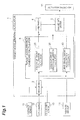
- Fig. 1 is a block configuration diagram of a vehicle cruise control apparatus according to the present invention
- Fig. 2 a block configuration diagram of a curve-travel target acceleration calculator.
- the vehicle cruise control apparatus is equipped with a target acceleration calculator 1.
- the target acceleration calculator 1 is provided with a recognizer 2, a target acceleration candidate calculator 3, an arbitrator 4, and a change rate limiter 5.
- the following elements are connected to the target acceleration calculator 1: a distance sensor 11, a CCD camera 12, a vehicle speed sensor 13, a yaw rate sensor 14 as curve state detecting means of the present invention, and an actuator selector 15 as controlling means of the present invention.
- the target acceleration candidate calculator 3 is provided with a follow-up target acceleration calculator 20 as relative relation calculating means and first calculating means of the present invention, a constant-speed target acceleration calculator 30, and a curve-travel target acceleration calculator 40 as specification setting means.
- the curve-travel target acceleration calculator 40 is provided, as shown in Fig. 2, with a specification memory 41, a first curve-travel target acceleration calculator 42 as third calculating means of the present invention, a second curve-travel target acceleration calculator 43 as second calculating means of the present invention, and a selector 44.
- the distance sensor 11 is comprised, for example, of a millimeter-wave radar sensor mounted at the front end of the host vehicle and detects a distance to a preceding vehicle as a target object of the present invention located in front of the host vehicle.
- the distance sensor 11 transmits the detected distance between the preceding vehicle and the host vehicle to the recognizer 2 in the target acceleration calculator 1.
- the CCD camera 12 is located, for example, in the vicinity of the windshield of the host vehicle and takes an image in front of the host vehicle.
- the CCD camera 12 transmits the taken image to the recognizer 2 in the target acceleration calculator 1.
- the vehicle speed sensor 13 is mounted, for example, in the body of the host vehicle and detects the vehicle speed of the host vehicle.
- the vehicle speed sensor 13 transmits the detected vehicle speed to the recognizer 2.
- the yaw rate sensor 14 is mounted, for example, in the body of the host vehicle and detects the yaw rate in the host vehicle.
- the yaw rate sensor 14 transmits the detected yaw rate to the curve-travel target acceleration calculator 40.
- the recognizer 2 performs image processing of the image transmitted from the CCD camera 12, to recognize white lines drawn on a road, and obstacles on the road.
- the recognizer 2 calculates a relative distance, a relative speed, and a relative acceleration to the preceding vehicle, based on the distance information transmitted from the distance sensor 11.
- the recognizer 2 transmits the calculated relative distance, relative speed, and relative acceleration to the preceding vehicle to the follow-up target acceleration calculator 20 and to the curve-travel target acceleration calculator 40 in the target acceleration candidate calculator 3. Furthermore, the recognizer 2 transmits the transmitted vehicle speed from the vehicle speed sensor 13 to the follow-up target acceleration calculator 20 and to the curve-travel target acceleration calculator 40.
- the follow-up target acceleration calculator 20 stores a target inter-vehicular time ht used in calculation of a target inter-vehicular distance, and uses this target inter-vehicular time ht and the vehicle speed of the host vehicle transmitted from the recognizer 2, to calculate the target inter-vehicular distance AL, based on Eq (1) below.
- AL ht * V
- the follow-up target acceleration calculator 20 stores control gains K.1, K2 for calculation of a target acceleration, and uses the calculated target inter-vehicular distance AL, the inter-vehicular distance L and relative speed VR to the preceding vehicle transmitted from the recognizer 2, and the stored control gains K1, K2 to calculate a follow-up target acceleration atf, based on Eq (2) below.
- the follow-up target acceleration calculator 20 transmits the calculated follow-up target acceleration atf to the arbitrator 4.
- arf K ⁇ 1 ⁇ L - AL + K ⁇ 2 * VR
- the constant-speed target acceleration calculator 30 calculates a constant-speed target acceleration atu being a target acceleration for travel at a set vehicle speed, and transmits the calculated constant-speed target acceleration atu to the arbitrator 4.
- the specification memory 41 in the curve-travel target acceleration calculator 40 preliminarily stores a predetermined control gain K, a gentle-curve allowable lateral acceleration G1 as an allowable lateral acceleration for a gentle curve with a large curve radius as a curve state, and a sharp-curve allowable lateral acceleration G2 as an allowable lateral acceleration for a sharp curve with a small curve radius.
- the specification memory 41 constitutes the specification storing means of the present invention.
- a curve tolerance is a value defined by a lateral acceleration in the present embodiment; the gentle-curve allowable lateral acceleration G1 corresponds to the second curve tolerance of the present invention, and the sharp-curve allowable lateral acceleration G2 to the first curve tolerance of the present invention.
- the control gain K herein can be set to a predetermined value for use in calculation of the target acceleration from a deviation between a target speed and an actual speed of the host vehicle.
- the allowable lateral accelerations herein are preliminarily set as a plurality of lateral accelerations in accordance with levels of sharpness felt by the driver during travel on curves. Specifically, for example, 0.15G is set as the gentle-curve allowable lateral acceleration G1, and 0.3G as the sharp-curve allowable lateral acceleration G2. Furthermore, since the lateral acceleration 0.3G as a curve tolerance allows up to a sharper curve state than the lateral acceleration 0.15G as a curve tolerance, a curve tolerance defined by a larger value of lateral acceleration allows up to a sharper curve.
- the specification memory 41 transmits the target speed Av and gentle-curve allowable lateral acceleration G1 to the first curve-travel target acceleration calculator 42, and transmits the target speed Av and sharp-curve allowable lateral acceleration G2 to the second curve-travel target acceleration calculator 43.
- the first curve-travel target acceleration calculator 42 calculates a curve radius R, based on the yaw rate transmitted from the yaw rate sensor 14.
- the first curve-travel target acceleration calculator 42 uses the calculated curve radius R and the gentle-curve allowable lateral acceleration G1 transmitted from the specification memory 41, to calculate a first target speed Av1, using Eq (3) below.
- Av ⁇ 1 sqrt R * G ⁇ 1
- the first curve-travel target acceleration calculator 42 uses the calculated first target speed Av1 and the vehicle speed v of the host vehicle transmitted from the recognizer 2, to calculate a first target acceleration at1, based on Eq (4) below. Furthermore, the first curve-travel target acceleration calculator 42 sets, for example, 0G as a lower limit for the first target acceleration at1. Therefore, the first curve-travel target acceleration calculator 42 compares the calculated first target acceleration at1 with 0G as the lower limit and, when the first target acceleration at1 is smaller than 0Q it adopts the lower limit of 0G as the first target acceleration at1.
- the first curve-travel target acceleration calculator 42 transmits the calculated first target acceleration at1 (or the lower limit of 0G when the calculated first target acceleration at1 is smaller than the lower limit) to the selector 44.
- ⁇ 1 K * Av ⁇ 1 - v
- the second curve-travel target acceleration calculator 43 uses the curve radius R and the sharp-curve allowable lateral acceleration G2 transmitted from the specification memory 41, to calculate a second target speed Av2, using Eq (5) below.
- Av ⁇ 2 sqrt R * G ⁇ 2
- the second curve-travel target acceleration calculator 43 uses the calculated second target speed Av2 and the vehicle speed v of the host vehicle transmitted from the recognizer 2, to calculate a second target acceleration at2, based on Eq (6) below. Furthermore, the second curve-travel target acceleration calculator 43 sets, for example, -0.3G as a lower limit for the second target acceleration at2. Therefore, the second curve-travel target acceleration calculator 43 compares the calculated second target acceleration at2 with the lower limit of -0.3G and, when the second target acceleration at2 is smaller than -0.3G, it adopts the lower limit of -0.3G as the second target acceleration at2.
- the second curve-travel target acceleration calculator 43 transmits the calculated second target acceleration at2 (or the lower limit of -0.3G when the calculated second target acceleration at2 is smaller than the lower limit) to the selector 44.
- ⁇ 2 K * Av ⁇ 2 - v
- the selector 44 compares the first target acceleration at1 transmitted from the first curve-travel target acceleration calculator 42, with the second target acceleration at2 transmitted from the second curve-travel target acceleration calculator 43. Then it selects the smaller out of the first target acceleration at1 and the second target acceleration at2, as a curve-travel target acceleration atc and transmits it to the arbitrator 4.
- the arbitrator 4 performs an arbitration among the three target accelerations atf, atu, atc transmitted from the follow-up target acceleration calculator 20, the constant-speed target acceleration calculator 30, and the curve-travel target acceleration calculator 40 and determines the smallest target acceleration as a target acceleration at. Then the arbitrator 4 transmits the target acceleration determined in this manner, to the change rate limiter 5.
- the change rate limiter 5 stores a predetermined limit value for change rates of acceleration of the host vehicle.
- the change rate limiter 5 compares the target acceleration transmitted from the arbitrator 4, with the stored limit value and, when the change rate of acceleration does not exceed the limit value, it adopts the target acceleration transmitted from the arbitrator 4, as the target acceleration as it is. When the target acceleration transmitted from the arbitrator 4 exceeds the limit value, the change rate limiter 5 adopts the limit value as the target acceleration.
- the change rate limiter 5 transmits the adopted target acceleration to the actuator selector 15.
- the actuator selector 15 is connected to an unrepresented engine controller and to an unrepresented brake controller; when the adopted target acceleration is positive, it transmits the target acceleration to the engine controller; when the adopted target acceleration is negative, it transmits the target acceleration to the brake controller.
- the engine controller and the brake controller control the engine and the brake, respectively, so as to achieve the transmitted target acceleration.
- Fig. 3 is a flowchart showing the procedure of the cruise control according to the present embodiment
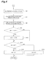
- Fig. 4 a flowchart subsequent to Fig. 3.
- the below will describe the procedure of control in the curve-travel target acceleration calculator 40 which is a characteristic part of the present embodiment.
- the cruise control involves the first step in which the first curve-travel target acceleration calculator 42 sets the allowable lateral acceleration to the gentle-curve allowable lateral acceleration G1 (S1).
- This gentle-curve allowable lateral acceleration G1 is set to 0.15G.
- the first target speed Av1 is calculated based on the aforementioned Eq (3), in order to determine a vehicle speed for achievement of this gentle-curve allowable lateral acceleration G1 as the first target speed Av1 (S2).
- the first target acceleration at1 is calculated based on the aforementioned Eq (4), in order to determine an acceleration for achievement of this first target speed Av1 (S3).
- the first target acceleration at1 After the first target acceleration at1 is calculated in this manner, it is determined whether the first target acceleration at1 is less than 0 (S4). When it is determined that the first target acceleration at1 is less than 0, the first target acceleration at1 is set to 0; when the first target acceleration at1 is not less than 0, the calculated first target acceleration at1 is adopted as the first target acceleration at1 as it is.
- the vehicle can be prevented from being controlled in acceleration on a gentle curve because the control of braking/driving force is executed with the lower limit of 0G as the target acceleration on the gentle curve with which the follow-up target acceleration calculator 20 as the first calculating means calculates a smaller first target acceleration at1 and the second curve-travel target acceleration calculator 43 as the second calculating means calculates the second target acceleration at2 larger than the lower limit of 0G.
- the second curve-travel target acceleration calculator 43 sets the allowable lateral acceleration to the sharp-curve allowable lateral acceleration G2 larger than the gentle-curve allowable lateral acceleration G1, as shown in Fig. 4 (S6).
- the sharp-curve allowable lateral acceleration G2 is set to 0.3G.
- the second target speed Av2 is calculated based on the aforementioned Eq (5), in order to determine a vehicle speed for achievement of this sharp-curve allowable lateral acceleration G2, as the second target speed Av2 (S7). Furthermore, the second target acceleration at2 is calculated based on the foregoing Eq (6), in order to determine an acceleration for achievement of this second target speed Av2 (S8).
- the vehicle can be prevented from being controlled in acceleration on a gentle curve because the control of braking/driving force is carried out with the lower limit of 0G as the target acceleration on the gentle curve with which the follow-up target acceleration calculator 20 as the first calculating means calculates the first target acceleration at1 smaller than the lower limit of 0G and the second curve-travel target acceleration calculator 43 as the second calculating means calculates the second target acceleration at2 larger than the lower limit of 0G.
- deceleration control of the vehicle is carried out while the second target acceleration at2 calculated by the first curve-travel target acceleration calculator 42 as the third calculating means is selected, from a constant-speed state with the target acceleration of 0G. Therefore, the deceleration can be effected with a smaller deceleration shock than in the case where the deceleration is suddenly imparted. Therefore, suddenly decelerated cases are reduced at the entrance of sharp curves, which prevents degradation of ride quality for occupants during travel on sharp curves.
- the second target acceleration at2 After the second target acceleration at2 is calculated in this way, it is determined whether the second target acceleration at2 is less than -0.3G (S9). When it is determined that the second target acceleration at2 is less than -0.3G, the second target acceleration at2 is set to -0.3G (S10); when the second target acceleration at2 is not less than -0.3G, the calculated second target acceleration at2 is adopted as the second target acceleration at2 as it is.
- the first target acceleration at1 is calculated in step S6 and the second target acceleration at2 in step S11 as described above, it is determined whether the first target acceleration at1 is smaller than the second target acceleration at2 (S11). When it is determined that the first target acceleration at1 is smaller than the second target acceleration, the first target acceleration at1 is selected as the curve-travel target acceleration atc (S12). When the first target acceleration at1 is not less than the second target acceleration, the second target acceleration at2 is selected as the curve-travel target acceleration atc (S13).
- the first target acceleration at1 will always be smaller than the second target acceleration at2.
- the second target acceleration at2 will not be used and the same target acceleration as in travel on gentle curves will be set in travel on sharp curves, so as to effect large deceleration on the sharp curves, which can cause degradation of ride quality.
- the host vehicle can be decelerated at the acceleration determined in view of the ride quality during travel on sharp curves. Therefore, it can prevent degradation of ride quality for occupants during travel on sharp curves.
- Fig. 5 is a flowchart showing the procedure of finally calculating the target acceleration.
- the follow-up target acceleration calculator 20 first calculates the follow-up target acceleration atf (S21). The calculation of the follow-up target acceleration atf is carried out based on the aforementioned Eq (2).
- the follow-up target acceleration calculator 20 transmits the calculated follow-up target acceleration atf to the arbitrator 4.
- the constant-speed target acceleration calculator 30 calculates the constant-speed target acceleration atu (S22).
- the constant-speed target acceleration calculator 30 transmits the calculated constant-speed target acceleration atu to the arbitrator 4.
- the curve-travel target acceleration calculator 40 calculates the curve-travel target acceleration atc (S23).
- the calculation of the curve-travel target acceleration atc is carried out according to the procedure of the flowcharts shown in Figs. 3 and 4.
- the curve-travel target acceleration calculator 40 transmits the calculated curve-travel target acceleration atc to the arbitrator 4.
- the arbitrator 4 compares the follow-up target acceleration atf, the constant-speed target acceleration atu, and the curve-travel target acceleration atc transmitted from the follow-up target acceleration calculator 20, from the constant-speed target acceleration calculator 30, and from the curve-travel target acceleration calculator 40, respectively, selects the minimum out of them, and sets the minimum as the target acceleration at (S24).
- the target acceleration is determined in this manner.
- Fig. 6 is graphs showing temporal changes of target accelerations, wherein (a) shows temporal changes of the follow-up target acceleration atf, the first target acceleration at1, and the second target acceleration at2 and (b) a temporal change of target acceleration outputted from the arbitrator 4.
- the follow-up target acceleration atf remains at an almost constant acceleration during travel of the host vehicle from a straight line to curves.
- the first target acceleration at1 and the second target acceleration at2 both indicate large values.
- the first target acceleration at1 reduces and becomes smaller than the follow-up target acceleration atf with time.
- the first target acceleration at1 remains at the value of 0 after the target acceleration becomes 0.
- the second target acceleration at2 reduces with a lag from the first target acceleration at1 but always maintains a value larger than the first target acceleration at1.
- the second target acceleration at2 becomes smaller than the value of 0 as the target acceleration.
- the second target acceleration at2 becomes smaller than the first target acceleration at1.
- the second target acceleration at2 starts increasing in the second half of the travel on the sharp curve.
- the vehicle then enters a zone X4 where it travels on a gentle curve, the second target acceleration at2 exceeds 0 and becomes over the first target acceleration at1.
- the first target acceleration at1 also increases and the first target acceleration at1 becomes over the follow-up target acceleration atf.
- the first target acceleration at1 and the second target acceleration at2 both become larger than the follow-up target acceleration atf.
- the follow-up target acceleration atf is always selected in the zones X1, X5 where the host vehicle travels on the straight line, as shown in Fig. 6 (b).
- the first target acceleration at1 is selected from the point of time when the first target acceleration at1 becomes smaller than the follow-up target acceleration atf. For this reason, the vehicle can be prevented from being decelerated more than necessary on the gentle curve.
- the second target acceleration at2 is selected at the point of time when the second target acceleration at2 becomes smaller than the first target acceleration at1. For this reason, it becomes feasible to prevent failure in deceleration on the sharp curve and to prevent degradation of ride quality for occupants.
- the present invention is by no means limited to the above embodiment.
- the above embodiment was arranged so that the curve-travel target acceleration calculator 40 set the first target acceleration at1 for gentle curves and the second target acceleration at2 for sharp curves, but it is also possible to adopt a configuration wherein more target accelerations are set according to states of curves.
- the above embodiment was arranged to set the speed control amount from the calculated target acceleration, but it is also possible, for example, to adopt configurations wherein the target speed is directly calculated and wherein the target speed is set from a target driving force control amount.
- the above embodiment used the target inter-vehicular distance as the target relative relation to the target object, but it is also possible to use a target inter-vehicular time or a target relative time.
- the above embodiment was arranged to use the preset and stored values for these relative target relation and curve tolerances, but it is also possible, fore example, to adopt a configuration wherein the driver sets them by a switch, a lever, or the like, or a configuration wherein they are automatically set from the driving characteristics, age, etc. of the driver.
- the lower limit may be any value other than 0G: for example, it is also possible to adopt a configuration wherein a negative lower limit, e.g., -0.01G is set to apply a deceleration, or a configuration wherein, conversely, a positive lower limit, e.g., 0.02G is set.
- a negative lower limit e.g., -0.01G
- a positive lower limit e.g. 0.02G
- the present invention allows the host vehicle to travel safely on curves, irrespective of accelerating and decelerating states of the preceding vehicle, on the occasion of performing the cruise control while following the preceding vehicle.
- the present invention relates to the vehicle cruise control apparatus and is applicable, particularly, to the vehicle cruise control apparatus for controlling the host vehicle to travel to follow the preceding vehicle.
Landscapes
- Engineering & Computer Science (AREA)
- Transportation (AREA)
- Mechanical Engineering (AREA)
- Automation & Control Theory (AREA)
- Chemical & Material Sciences (AREA)
- Combustion & Propulsion (AREA)
- Control Of Driving Devices And Active Controlling Of Vehicle (AREA)
- Controls For Constant Speed Travelling (AREA)
- Control Of Vehicle Engines Or Engines For Specific Uses (AREA)
- Traffic Control Systems (AREA)
- Regulating Braking Force (AREA)
Abstract
Description
- The present invention relates to vehicle cruise control apparatus and, more particularly, to a vehicle cruise control apparatus for controlling a host vehicle to travel to follow a preceding vehicle.
- In recent years, the vehicle cruise control apparatus for controlling the host vehicle to travel to follow a preceding vehicle traveling ahead has been developed in order to reduce the manipulation load on the driver driving the vehicle. This cruise control apparatus is arranged to control the acceleration of the host vehicle, for example, so that the inter-vehicular distance between the preceding vehicle detected by a sensor such as a camera or a radar, and the host vehicle becomes a target inter-vehicular distance.
- An example of such cruise control apparatus is the automatic follow-up control apparatus disclosed in
Japanese Patent Application Laid-Open No. 2003-200751 - The cruise control apparatus disclosed in the above-mentioned
Patent Document 1 is arranged to calculate the acceleration of the host vehicle by addition of an acceleration for the follow-up control and an acceleration for safe travel on the curve. For this reason, for example, when the preceding vehicle accelerates in the middle of the curve, the acceleration is calculated to follow the acceleration of the preceding vehicle, which posed the problem that adequate deceleration was not implemented for the host vehicle. - An object of the present invention is therefore to provide a vehicle cruise control apparatus capable of implementing safe travel of a host vehicle on curves, irrespective of accelerating and decelerating states of a preceding vehicle, on the occasion of performing cruise control while following the preceding vehicle.
- A vehicle cruise control apparatus according to the present invention, achieving the above object, is a vehicle cruise control apparatus comprising relative relation calculating means for calculating a relative relation between a target object detected by object detecting means, and a host vehicle; specification setting means for setting a target relative relation being a relative relation as a target, and for setting a first curve tolerance defining an allowable curve state; first calculating means for calculating a first speed control amount on the basis of the relative relation and the target relative relation; second calculating means for calculating a second speed control amount on the basis of the first curve tolerance; and controlling means for controlling a braking/driving force of the vehicle on the basis of a minimum out of the first speed control amount and the second speed control amount.
- The vehicle cruise control apparatus according to the present invention comprises the first calculating means for calculating the first speed control amount on the basis of the target relative relation and the relative relation, and the second calculating means for calculating the second speed control amount on the basis of the first curve tolerance defining the allowable curve state, and the braking/driving force of the vehicle is controlled based on the minimum out of the speed control amounts calculated by these calculating means. For this reason, the control is effected so as to achieve a safe vehicle speed in various situations, for example, including a case where the inter-vehicular distance becomes short during travel at a speed at which the vehicle can safely travel on a curve, a case where the inter-vehicular distance is large during travel on a curve, and a case where the vehicle goes into a curve while catching up with a preceding vehicle. Therefore, the host vehicle is able to safely travel on a curve, irrespective of accelerating and decelerating states of the preceding vehicle.
- The "speed control amounts" stated in the present invention embrace speed control amounts to directly control the speed of the vehicle, and amounts capable of controlling the speed of the vehicle as a result of control, such as acceleration control amounts and driving force control amounts. The "target relative relation" in the present invention refers to a target of a relative relation between the target object and the host vehicle and, for example, when the target object is a preceding vehicle, specific examples of the target relative relation are a target inter-vehicular distance, a target inter-vehicular time, a target relative speed, and so on. Furthermore, the "curve state" in the present invention can be expressed, for example, by a curve radius (radius of curvature), a curvature of a curve, or the like.
- It is also possible to adopt a configuration wherein the specification setting means further sets a second curve tolerance defining a gentler allowable curve state than the first curve tolerance; the vehicle cruise control apparatus further comprises third speed calculating means for calculating a second speed control amount on the basis of the second curve tolerance and for, when the third speed control amount is smaller than a lower limit defining a minimum of the third speed control amount, calculating the third speed control amount as being the lower limit; the controlling means controls the braking/driving force of the vehicle on the basis of a minimum out of the first speed control amount, the second speed control amount, and the third speed control amount.
- In a case where there is only one curve tolerance, if the curve tolerance is set in accordance with gentle curves, the deceleration will be too large; if the curve tolerance is set in accordance with sharp curves to the contrary, the deceleration will be too small on gentle curves. It is also conceivable to adopt a configuration of simply setting the first curve tolerance for sharp curves and the second curve tolerance for gentle curves, calculating the second speed control amount on the basis of the first curve tolerance, and calculating the third speed control amount on the basis of the second curve tolerance. In this case, however, the third speed control amount will always become smaller between the second speed control amount and the third speed control amount, and the third speed control amount will never be selected, which fails to solve the problem in the case where there is only one curve tolerance. Therefore, the cruise control apparatus according to the present invention is arranged to set the lower limit for the third speed control amount and to set this lower limit as the third speed control amount when the third speed control amount becomes smaller than the lower limit. Therefore, the second speed control amount is adopted when the second speed control amount is smaller than the lower limit of the third speed control amount, and this achieves utilization of the second speed control amount and the third speed control amount and thus well solves the problem in the case where there is only one curve tolerance.
- It is also possible to adopt a configuration wherein the lower limit is 0.
- When the lower limit of the third speed control amount is set to 0 in this manner, the host vehicle travels without acceleration during travel on a gentle curve. Therefore, the deceleration can be securely implemented in necessary situations.
- The scope of further application of the present invention will become apparent from the following detailed description of the invention. It is, however, noted that the detailed description and specific examples, while illustrating the preferred embodiments of the present invention, are presented by way of illustration only and it is apparent that various modifications and improvements within the spirit and scope of the present invention are obvious to those skilled in the art in view of the detailed description.
-
- Fig. 1 is a bock configuration diagram of a vehicle cruise control apparatus according to the present invention.
- Fig. 2 is a block configuration diagram of a curve-travel target acceleration calculator.
- Fig. 3 is a flowchart showing a procedure of cruise control.
- Fig. 4 is a flowchart showing a procedure subsequent to Fig. 3.
- Fig. 5 is a flowchart showing a procedure of finally calculating a target acceleration.
- Fig. 6 includes (a) a graph showing temporal changes of follow-up target acceleration, first target acceleration, and second target acceleration, and (b) a graph showing a temporal change of target acceleration.
- A preferred embodiment of the present invention will be described below with reference to the drawings. Fig. 1 is a block configuration diagram of a vehicle cruise control apparatus according to the present invention, and Fig. 2 a block configuration diagram of a curve-travel target acceleration calculator.
- As shown in Fig. 1, the vehicle cruise control apparatus according to the present embodiment is equipped with a
target acceleration calculator 1. Thetarget acceleration calculator 1 is provided with arecognizer 2, a targetacceleration candidate calculator 3, anarbitrator 4, and achange rate limiter 5. The following elements are connected to the target acceleration calculator 1: adistance sensor 11, aCCD camera 12, avehicle speed sensor 13, ayaw rate sensor 14 as curve state detecting means of the present invention, and anactuator selector 15 as controlling means of the present invention. Furthermore, the targetacceleration candidate calculator 3 is provided with a follow-uptarget acceleration calculator 20 as relative relation calculating means and first calculating means of the present invention, a constant-speedtarget acceleration calculator 30, and a curve-traveltarget acceleration calculator 40 as specification setting means. The curve-traveltarget acceleration calculator 40 is provided, as shown in Fig. 2, with aspecification memory 41, a first curve-traveltarget acceleration calculator 42 as third calculating means of the present invention, a second curve-traveltarget acceleration calculator 43 as second calculating means of the present invention, and aselector 44. - The
distance sensor 11 is comprised, for example, of a millimeter-wave radar sensor mounted at the front end of the host vehicle and detects a distance to a preceding vehicle as a target object of the present invention located in front of the host vehicle. Thedistance sensor 11 transmits the detected distance between the preceding vehicle and the host vehicle to therecognizer 2 in thetarget acceleration calculator 1. TheCCD camera 12 is located, for example, in the vicinity of the windshield of the host vehicle and takes an image in front of the host vehicle. TheCCD camera 12 transmits the taken image to therecognizer 2 in thetarget acceleration calculator 1. Thevehicle speed sensor 13 is mounted, for example, in the body of the host vehicle and detects the vehicle speed of the host vehicle. Thevehicle speed sensor 13 transmits the detected vehicle speed to therecognizer 2. Furthermore, theyaw rate sensor 14 is mounted, for example, in the body of the host vehicle and detects the yaw rate in the host vehicle. Theyaw rate sensor 14 transmits the detected yaw rate to the curve-traveltarget acceleration calculator 40. - The
recognizer 2 performs image processing of the image transmitted from theCCD camera 12, to recognize white lines drawn on a road, and obstacles on the road. Therecognizer 2 calculates a relative distance, a relative speed, and a relative acceleration to the preceding vehicle, based on the distance information transmitted from thedistance sensor 11. Therecognizer 2 transmits the calculated relative distance, relative speed, and relative acceleration to the preceding vehicle to the follow-uptarget acceleration calculator 20 and to the curve-traveltarget acceleration calculator 40 in the targetacceleration candidate calculator 3. Furthermore, therecognizer 2 transmits the transmitted vehicle speed from thevehicle speed sensor 13 to the follow-uptarget acceleration calculator 20 and to the curve-traveltarget acceleration calculator 40. - The follow-up
target acceleration calculator 20 stores a target inter-vehicular time ht used in calculation of a target inter-vehicular distance, and uses this target inter-vehicular time ht and the vehicle speed of the host vehicle transmitted from therecognizer 2, to calculate the target inter-vehicular distance AL, based on Eq (1) below.
- The follow-up
target acceleration calculator 20 stores control gains K.1, K2 for calculation of a target acceleration, and uses the calculated target inter-vehicular distance AL, the inter-vehicular distance L and relative speed VR to the preceding vehicle transmitted from therecognizer 2, and the stored control gains K1, K2 to calculate a follow-up target acceleration atf, based on Eq (2) below. The follow-uptarget acceleration calculator 20 transmits the calculated follow-up target acceleration atf to thearbitrator 4.
- The constant-speed
target acceleration calculator 30 calculates a constant-speed target acceleration atu being a target acceleration for travel at a set vehicle speed, and transmits the calculated constant-speed target acceleration atu to thearbitrator 4. - The
specification memory 41 in the curve-traveltarget acceleration calculator 40 preliminarily stores a predetermined control gain K, a gentle-curve allowable lateral acceleration G1 as an allowable lateral acceleration for a gentle curve with a large curve radius as a curve state, and a sharp-curve allowable lateral acceleration G2 as an allowable lateral acceleration for a sharp curve with a small curve radius. Thespecification memory 41 constitutes the specification storing means of the present invention. A curve tolerance is a value defined by a lateral acceleration in the present embodiment; the gentle-curve allowable lateral acceleration G1 corresponds to the second curve tolerance of the present invention, and the sharp-curve allowable lateral acceleration G2 to the first curve tolerance of the present invention. - The control gain K herein can be set to a predetermined value for use in calculation of the target acceleration from a deviation between a target speed and an actual speed of the host vehicle. The allowable lateral accelerations herein are preliminarily set as a plurality of lateral accelerations in accordance with levels of sharpness felt by the driver during travel on curves. Specifically, for example, 0.15G is set as the gentle-curve allowable lateral acceleration G1, and 0.3G as the sharp-curve allowable lateral acceleration G2. Furthermore, since the lateral acceleration 0.3G as a curve tolerance allows up to a sharper curve state than the lateral acceleration 0.15G as a curve tolerance, a curve tolerance defined by a larger value of lateral acceleration allows up to a sharper curve. Conversely, since the lateral acceleration 0.15G as a curve tolerance allows merely up to a gentler curve state than the lateral acceleration 0.3G as a curve tolerance, a curve tolerance defined by a smaller value of lateral acceleration allows merely up to a gentler curve state. The
specification memory 41 transmits the target speed Av and gentle-curve allowable lateral acceleration G1 to the first curve-traveltarget acceleration calculator 42, and transmits the target speed Av and sharp-curve allowable lateral acceleration G2 to the second curve-traveltarget acceleration calculator 43. - The first curve-travel
target acceleration calculator 42 calculates a curve radius R, based on the yaw rate transmitted from theyaw rate sensor 14. The first curve-traveltarget acceleration calculator 42 uses the calculated curve radius R and the gentle-curve allowable lateral acceleration G1 transmitted from thespecification memory 41, to calculate a first target speed Av1, using Eq (3) below.
- The first curve-travel
target acceleration calculator 42 uses the calculated first target speed Av1 and the vehicle speed v of the host vehicle transmitted from therecognizer 2, to calculate a first target acceleration at1, based on Eq (4) below. Furthermore, the first curve-traveltarget acceleration calculator 42 sets, for example, 0G as a lower limit for the first target acceleration at1. Therefore, the first curve-traveltarget acceleration calculator 42 compares the calculated first target acceleration at1 with 0G as the lower limit and, when the first target acceleration at1 is smaller than 0Q it adopts the lower limit of 0G as the first target acceleration at1. In this manner, the first curve-traveltarget acceleration calculator 42 transmits the calculated first target acceleration at1 (or the lower limit of 0G when the calculated first target acceleration at1 is smaller than the lower limit) to theselector 44.
- The second curve-travel
target acceleration calculator 43 uses the curve radius R and the sharp-curve allowable lateral acceleration G2 transmitted from thespecification memory 41, to calculate a second target speed Av2, using Eq (5) below.
- The second curve-travel
target acceleration calculator 43 uses the calculated second target speed Av2 and the vehicle speed v of the host vehicle transmitted from therecognizer 2, to calculate a second target acceleration at2, based on Eq (6) below. Furthermore, the second curve-traveltarget acceleration calculator 43 sets, for example, -0.3G as a lower limit for the second target acceleration at2. Therefore, the second curve-traveltarget acceleration calculator 43 compares the calculated second target acceleration at2 with the lower limit of -0.3G and, when the second target acceleration at2 is smaller than -0.3G, it adopts the lower limit of -0.3G as the second target acceleration at2. In this manner, the second curve-traveltarget acceleration calculator 43 transmits the calculated second target acceleration at2 (or the lower limit of -0.3G when the calculated second target acceleration at2 is smaller than the lower limit) to theselector 44.
- The
selector 44 compares the first target acceleration at1 transmitted from the first curve-traveltarget acceleration calculator 42, with the second target acceleration at2 transmitted from the second curve-traveltarget acceleration calculator 43. Then it selects the smaller out of the first target acceleration at1 and the second target acceleration at2, as a curve-travel target acceleration atc and transmits it to thearbitrator 4. - The
arbitrator 4 performs an arbitration among the three target accelerations atf, atu, atc transmitted from the follow-uptarget acceleration calculator 20, the constant-speedtarget acceleration calculator 30, and the curve-traveltarget acceleration calculator 40 and determines the smallest target acceleration as a target acceleration at. Then thearbitrator 4 transmits the target acceleration determined in this manner, to thechange rate limiter 5. - The
change rate limiter 5 stores a predetermined limit value for change rates of acceleration of the host vehicle. Thechange rate limiter 5 compares the target acceleration transmitted from thearbitrator 4, with the stored limit value and, when the change rate of acceleration does not exceed the limit value, it adopts the target acceleration transmitted from thearbitrator 4, as the target acceleration as it is. When the target acceleration transmitted from thearbitrator 4 exceeds the limit value, thechange rate limiter 5 adopts the limit value as the target acceleration. - The
change rate limiter 5 transmits the adopted target acceleration to theactuator selector 15. Theactuator selector 15 is connected to an unrepresented engine controller and to an unrepresented brake controller; when the adopted target acceleration is positive, it transmits the target acceleration to the engine controller; when the adopted target acceleration is negative, it transmits the target acceleration to the brake controller. The engine controller and the brake controller control the engine and the brake, respectively, so as to achieve the transmitted target acceleration. - The following will describe a procedure of the cruise control by the cruise control apparatus according to the present embodiment. Fig. 3 is a flowchart showing the procedure of the cruise control according to the present embodiment, and Fig. 4 a flowchart subsequent to Fig. 3. The below will describe the procedure of control in the curve-travel
target acceleration calculator 40 which is a characteristic part of the present embodiment. - As shown in Fig. 3, for calculation of the curve-travel target acceleration atc, the cruise control according to the present embodiment involves the first step in which the first curve-travel
target acceleration calculator 42 sets the allowable lateral acceleration to the gentle-curve allowable lateral acceleration G1 (S1). This gentle-curve allowable lateral acceleration G1 is set to 0.15G. Next, the first target speed Av1 is calculated based on the aforementioned Eq (3), in order to determine a vehicle speed for achievement of this gentle-curve allowable lateral acceleration G1 as the first target speed Av1 (S2). Furthermore, the first target acceleration at1 is calculated based on the aforementioned Eq (4), in order to determine an acceleration for achievement of this first target speed Av1 (S3). - After the first target acceleration at1 is calculated in this manner, it is determined whether the first target acceleration at1 is less than 0 (S4). When it is determined that the first target acceleration at1 is less than 0, the first target acceleration at1 is set to 0; when the first target acceleration at1 is not less than 0, the calculated first target acceleration at1 is adopted as the first target acceleration at1 as it is. When the lower limit of the first target acceleration at1 in travel on gentle curves is set to 0 as described above, the vehicle can be prevented from being controlled in acceleration on a gentle curve because the control of braking/driving force is executed with the lower limit of 0G as the target acceleration on the gentle curve with which the follow-up
target acceleration calculator 20 as the first calculating means calculates a smaller first target acceleration at1 and the second curve-traveltarget acceleration calculator 43 as the second calculating means calculates the second target acceleration at2 larger than the lower limit of 0G. - On the other hand, after the first target acceleration at1 is calculated with the gentle-curve allowable lateral acceleration G1 as the allowable lateral acceleration, the second curve-travel
target acceleration calculator 43 then sets the allowable lateral acceleration to the sharp-curve allowable lateral acceleration G2 larger than the gentle-curve allowable lateral acceleration G1, as shown in Fig. 4 (S6). The sharp-curve allowable lateral acceleration G2 is set to 0.3G. When the allowable lateral accelerations for travel on gentle curves and for travel on sharp curves are set as separate values in this manner, it is feasible to set accelerations according to the respective curves. - After the sharp-curve allowable lateral acceleration G2 is set in this manner, the second target speed Av2 is calculated based on the aforementioned Eq (5), in order to determine a vehicle speed for achievement of this sharp-curve allowable lateral acceleration G2, as the second target speed Av2 (S7). Furthermore, the second target acceleration at2 is calculated based on the foregoing Eq (6), in order to determine an acceleration for achievement of this second target speed Av2 (S8).
- In respect to it, the predetermined lower limit (G = 0) is set for the first target acceleration at1 in the present embodiment. For this reason, the vehicle can be prevented from being controlled in acceleration on a gentle curve because the control of braking/driving force is carried out with the lower limit of 0G as the target acceleration on the gentle curve with which the follow-up
target acceleration calculator 20 as the first calculating means calculates the first target acceleration at1 smaller than the lower limit of 0G and the second curve-traveltarget acceleration calculator 43 as the second calculating means calculates the second target acceleration at2 larger than the lower limit of 0G. Furthermore, when the vehicle comes to travel from a gentle curve to a sharp curve where the second target acceleration at2 is less than the lower limit of OG, deceleration control of the vehicle is carried out while the second target acceleration at2 calculated by the first curve-traveltarget acceleration calculator 42 as the third calculating means is selected, from a constant-speed state with the target acceleration of 0G. Therefore, the deceleration can be effected with a smaller deceleration shock than in the case where the deceleration is suddenly imparted. Therefore, suddenly decelerated cases are reduced at the entrance of sharp curves, which prevents degradation of ride quality for occupants during travel on sharp curves. - After the second target acceleration at2 is calculated in this way, it is determined whether the second target acceleration at2 is less than -0.3G (S9). When it is determined that the second target acceleration at2 is less than -0.3G, the second target acceleration at2 is set to -0.3G (S10); when the second target acceleration at2 is not less than -0.3G, the calculated second target acceleration at2 is adopted as the second target acceleration at2 as it is.
- After the first target acceleration at1 is calculated in step S6 and the second target acceleration at2 in step S11 as described above, it is determined whether the first target acceleration at1 is smaller than the second target acceleration at2 (S11). When it is determined that the first target acceleration at1 is smaller than the second target acceleration, the first target acceleration at1 is selected as the curve-travel target acceleration atc (S12). When the first target acceleration at1 is not less than the second target acceleration, the second target acceleration at2 is selected as the curve-travel target acceleration atc (S13).
- If the lower limit is not set for the first target acceleration at1, the first target acceleration at1 will always be smaller than the second target acceleration at2. For this reason, the second target acceleration at2 will not be used and the same target acceleration as in travel on gentle curves will be set in travel on sharp curves, so as to effect large deceleration on the sharp curves, which can cause degradation of ride quality.
- In contrast to it, the predetermined lower limit (= 0G) is set for the first target acceleration at1 in the present embodiment. For this reason, when the second target acceleration at2 is smaller than this lower limit, the second target acceleration at2 is smaller than the first target acceleration at1. In this case, the host vehicle can be decelerated at the acceleration determined in view of the ride quality during travel on sharp curves. Therefore, it can prevent degradation of ride quality for occupants during travel on sharp curves.
- Subsequently, the final calculation procedure of target acceleration will be described. Fig. 5 is a flowchart showing the procedure of finally calculating the target acceleration. As shown in Fig. 5, on the occasion of calculation of the target acceleration, the follow-up
target acceleration calculator 20 first calculates the follow-up target acceleration atf (S21). The calculation of the follow-up target acceleration atf is carried out based on the aforementioned Eq (2). The follow-uptarget acceleration calculator 20 transmits the calculated follow-up target acceleration atf to thearbitrator 4. Next, the constant-speedtarget acceleration calculator 30 calculates the constant-speed target acceleration atu (S22). The constant-speedtarget acceleration calculator 30 transmits the calculated constant-speed target acceleration atu to thearbitrator 4. - Furthermore, the curve-travel
target acceleration calculator 40 calculates the curve-travel target acceleration atc (S23). The calculation of the curve-travel target acceleration atc is carried out according to the procedure of the flowcharts shown in Figs. 3 and 4. The curve-traveltarget acceleration calculator 40 transmits the calculated curve-travel target acceleration atc to thearbitrator 4. Thearbitrator 4 compares the follow-up target acceleration atf, the constant-speed target acceleration atu, and the curve-travel target acceleration atc transmitted from the follow-uptarget acceleration calculator 20, from the constant-speedtarget acceleration calculator 30, and from the curve-traveltarget acceleration calculator 40, respectively, selects the minimum out of them, and sets the minimum as the target acceleration at (S24). The target acceleration is determined in this manner. - The following will describe an example of changes in target accelerations on the occasion of execution of the cruise control in the present embodiment. Fig. 6 is graphs showing temporal changes of target accelerations, wherein (a) shows temporal changes of the follow-up target acceleration atf, the first target acceleration at1, and the second target acceleration at2 and (b) a temporal change of target acceleration outputted from the
arbitrator 4. - As shown in Fig. 6 (a), it is assumed that the follow-up target acceleration atf remains at an almost constant acceleration during travel of the host vehicle from a straight line to curves. At this time, in a straight-travel zone X1 the first target acceleration at1 and the second target acceleration at2 both indicate large values. When the vehicle moves from this state into a zone X2 where it travels on a gentle curve, the first target acceleration at1 reduces and becomes smaller than the follow-up target acceleration atf with time. The first target acceleration at1 remains at the value of 0 after the target acceleration becomes 0. Furthermore, in the zone X2 the second target acceleration at2 reduces with a lag from the first target acceleration at1 but always maintains a value larger than the first target acceleration at1.
- When the vehicle then moves into a zone X3 where it travels on a sharp curve, the second target acceleration at2 becomes smaller than the value of 0 as the target acceleration. At this point, the second target acceleration at2 becomes smaller than the first target acceleration at1. Thereafter, the second target acceleration at2 starts increasing in the second half of the travel on the sharp curve. When the vehicle then enters a zone X4 where it travels on a gentle curve, the second target acceleration at2 exceeds 0 and becomes over the first target acceleration at1. Then the first target acceleration at1 also increases and the first target acceleration at1 becomes over the follow-up target acceleration atf. Thereafter, in a zone X5 where the vehicle travels on a straight line, the first target acceleration at1 and the second target acceleration at2 both become larger than the follow-up target acceleration atf.
- Therefore, as the target acceleration finally calculated in the
arbitrator 4, the follow-up target acceleration atf is always selected in the zones X1, X5 where the host vehicle travels on the straight line, as shown in Fig. 6 (b). In the zones X2, X4 where the vehicle travels on the gentle curve, the first target acceleration at1 is selected from the point of time when the first target acceleration at1 becomes smaller than the follow-up target acceleration atf. For this reason, the vehicle can be prevented from being decelerated more than necessary on the gentle curve. Furthermore, in the zone X3 where the vehicle travels on the sharp curve, the second target acceleration at2 is selected at the point of time when the second target acceleration at2 becomes smaller than the first target acceleration at1. For this reason, it becomes feasible to prevent failure in deceleration on the sharp curve and to prevent degradation of ride quality for occupants. - The preferred embodiment of the present invention was described above, but the present invention is by no means limited to the above embodiment. For example, the above embodiment was arranged so that the curve-travel
target acceleration calculator 40 set the first target acceleration at1 for gentle curves and the second target acceleration at2 for sharp curves, but it is also possible to adopt a configuration wherein more target accelerations are set according to states of curves. The above embodiment was arranged to set the speed control amount from the calculated target acceleration, but it is also possible, for example, to adopt configurations wherein the target speed is directly calculated and wherein the target speed is set from a target driving force control amount. - Furthermore, the above embodiment used the target inter-vehicular distance as the target relative relation to the target object, but it is also possible to use a target inter-vehicular time or a target relative time. On the other hand, the above embodiment was arranged to use the preset and stored values for these relative target relation and curve tolerances, but it is also possible, fore example, to adopt a configuration wherein the driver sets them by a switch, a lever, or the like, or a configuration wherein they are automatically set from the driving characteristics, age, etc. of the driver.
- The above embodiment adopted the lower limit of 0G, but the lower limit may be any value other than 0G: for example, it is also possible to adopt a configuration wherein a negative lower limit, e.g., -0.01G is set to apply a deceleration, or a configuration wherein, conversely, a positive lower limit, e.g., 0.02G is set. In the case of the configuration wherein more target accelerations are set according to states of curves, it is preferable to set a plurality of lower limits. Specifically, a lower limit corresponding to a gentle curve tolerance is set to a value larger than a lower limit corresponding to a sharper curve tolerance. This configuration permits the target acceleration to be calculated so as to become smaller in a stepwise fashion from the largest lower limit out of the set lower limits.
- As described above, the present invention allows the host vehicle to travel safely on curves, irrespective of accelerating and decelerating states of the preceding vehicle, on the occasion of performing the cruise control while following the preceding vehicle.
- The present invention relates to the vehicle cruise control apparatus and is applicable, particularly, to the vehicle cruise control apparatus for controlling the host vehicle to travel to follow the preceding vehicle.
Claims (3)
- A vehicle cruise control apparatus comprising:relative relation calculating means for calculating a relative relation between a target object detected by object detecting means, and a host vehicle;specification setting means for setting a target relative relation being a relative relation as a target, and for setting a first curve tolerance defining an allowable curve state;first calculating means for calculating a first speed control amount on the basis of the relative relation and the target relative relation;second calculating means for calculating a second speed control amount on the basis of the first curve tolerance; andcontrolling means for controlling a braking/driving force of the vehicle on the basis of a minimum out of the first speed control amount and the second speed control amount.
- The vehicle cruise control apparatus according to claim 1,
wherein the specification setting means further sets a second curve tolerance defining a gentler allowable curve state than the first curve tolerance;
the vehicle cruise control apparatus further comprising third speed calculating means for calculating a third speed control amount on the basis of the second curve tolerance and for, when the third speed control amount is smaller than a lower limit defining a minimum of the third speed control amount, calculating the third speed control amount as being the lower limit;
wherein the controlling means controls the braking/driving force of the vehicle on the basis of a minimum out of the first speed control amount, the second speed control amount, and the third speed control amount. - The vehicle cruise control apparatus according to claim 2, wherein the lower limit is 0.
Applications Claiming Priority (2)
| Application Number | Priority Date | Filing Date | Title |
|---|---|---|---|
| JP2005084441A JP3925540B2 (en) | 2005-03-23 | 2005-03-23 | Vehicle travel control device |
| PCT/JP2006/306592 WO2006101261A1 (en) | 2005-03-23 | 2006-03-23 | Running control device for vehicle |
Publications (3)
| Publication Number | Publication Date |
|---|---|
| EP1834855A1 true EP1834855A1 (en) | 2007-09-19 |
| EP1834855A4 EP1834855A4 (en) | 2009-09-09 |
| EP1834855B1 EP1834855B1 (en) | 2010-09-15 |
Family
ID=37023900
Family Applications (1)
| Application Number | Title | Priority Date | Filing Date |
|---|---|---|---|
| EP06730540A Expired - Lifetime EP1834855B1 (en) | 2005-03-23 | 2006-03-23 | Running control device for vehicle |
Country Status (6)
| Country | Link |
|---|---|
| US (1) | US7634346B2 (en) |
| EP (1) | EP1834855B1 (en) |
| JP (1) | JP3925540B2 (en) |
| CN (1) | CN100590011C (en) |
| DE (1) | DE602006016910D1 (en) |
| WO (1) | WO2006101261A1 (en) |
Cited By (1)
| Publication number | Priority date | Publication date | Assignee | Title |
|---|---|---|---|---|
| EP2853457A1 (en) * | 2013-09-30 | 2015-04-01 | Hitachi Ltd. | Method and apparatus for performing driving assistance |
Families Citing this family (23)
| Publication number | Priority date | Publication date | Assignee | Title |
|---|---|---|---|---|
| JP5054389B2 (en) * | 2007-02-06 | 2012-10-24 | 富士重工業株式会社 | Vehicle driving support device |
| JP5031482B2 (en) * | 2007-08-10 | 2012-09-19 | 株式会社デンソー | VEHICLE STOP CONTROL DEVICE AND CONTROL SYSTEM |
| JP4596016B2 (en) * | 2008-02-12 | 2010-12-08 | トヨタ自動車株式会社 | Vehicle travel control device |
| JP4730406B2 (en) * | 2008-07-11 | 2011-07-20 | トヨタ自動車株式会社 | Driving support control device |
| JP5363906B2 (en) * | 2009-08-05 | 2013-12-11 | 株式会社アドヴィックス | Vehicle speed control device |
| JP5324367B2 (en) | 2009-09-16 | 2013-10-23 | 株式会社デンソー | Control request arbitration device |
| JP5353863B2 (en) * | 2010-11-10 | 2013-11-27 | 三菱自動車工業株式会社 | Vehicle control device |
| DE102011102437A1 (en) * | 2011-05-25 | 2012-11-29 | Audi Ag | Method for operating a longitudinal driver assistance system of a motor vehicle and motor vehicle |
| JP5673597B2 (en) * | 2011-11-18 | 2015-02-18 | 株式会社デンソー | Vehicle behavior control device |
| JP5858149B2 (en) * | 2012-04-25 | 2016-02-10 | トヨタ自動車株式会社 | Meander determination device |
| KR102183049B1 (en) * | 2014-04-14 | 2020-11-25 | 주식회사 만도 | Adaptive cruise control system interlocking with lkas and method for controlling constant speed of the same |
| JP6301714B2 (en) * | 2014-04-14 | 2018-03-28 | 株式会社Soken | Travel route generator |
| JP6363519B2 (en) * | 2015-01-21 | 2018-07-25 | 株式会社デンソー | Vehicle control device |
| JP2017001485A (en) * | 2015-06-09 | 2017-01-05 | トヨタ自動車株式会社 | Vehicle driving support device |
| USD817539S1 (en) * | 2016-10-14 | 2018-05-08 | Feelux Co., Ltd. | Lighting apparatus |
| JP6801417B2 (en) * | 2016-12-08 | 2020-12-16 | 株式会社豊田自動織機 | Industrial vehicle |
| JP6665765B2 (en) * | 2016-12-08 | 2020-03-13 | 株式会社豊田自動織機 | Industrial vehicles |
| KR102751064B1 (en) * | 2016-12-15 | 2025-01-08 | 현대자동차주식회사 | Vehicle and method for controlling the same |
| JP6597590B2 (en) * | 2016-12-21 | 2019-10-30 | トヨタ自動車株式会社 | Driving assistance device |
| USD813442S1 (en) * | 2016-12-28 | 2018-03-20 | Feelux Co., Ltd. | Lighting device |
| JP6915578B2 (en) * | 2018-04-03 | 2021-08-04 | トヨタ自動車株式会社 | Vehicle control device |
| KR20220091076A (en) * | 2020-12-23 | 2022-06-30 | 현대자동차주식회사 | Vehicle and method for controlling thereof |
| JP2023179200A (en) * | 2022-06-07 | 2023-12-19 | 日立Astemo株式会社 | Vehicle motion control device and vehicle motion control method |
Family Cites Families (14)
| Publication number | Priority date | Publication date | Assignee | Title |
|---|---|---|---|---|
| JPS63151528A (en) | 1986-12-16 | 1988-06-24 | Mitsubishi Electric Corp | Controller for traveling of vehicle |
| DE19502954B4 (en) * | 1994-02-05 | 2011-06-16 | Volkswagen Ag | Method for controlling the speed of a motor vehicle |
| JPH08290728A (en) | 1995-04-21 | 1996-11-05 | Mitsubishi Motors Corp | Auto cruise control method |
| DE19624615C2 (en) | 1996-06-20 | 2001-09-20 | Volkswagen Ag | Distance control method for a motor vehicle |
| JP3223240B2 (en) | 1996-11-19 | 2001-10-29 | 本田技研工業株式会社 | Vehicle control device |
| WO1999028144A1 (en) * | 1997-12-01 | 1999-06-10 | Hitachi, Ltd. | Running controller for automobile |
| KR100572500B1 (en) | 1998-04-07 | 2006-04-24 | 로베르트 보쉬 게엠베하 | Vehicle stabilization method and device |
| DE19839858A1 (en) * | 1998-09-02 | 2000-03-09 | Zahnradfabrik Friedrichshafen | Process for cornering detection for a vehicle with an automatically shifting transmission |
| JP3167989B2 (en) * | 1999-08-10 | 2001-05-21 | 富士重工業株式会社 | Curve approach control device |
| JP3692911B2 (en) * | 2000-07-14 | 2005-09-07 | 日産自動車株式会社 | Vehicle tracking control device |
| JP3842036B2 (en) | 2000-12-04 | 2006-11-08 | 三菱電機株式会社 | Vehicle travel control device |
| JP2003200751A (en) | 2002-01-07 | 2003-07-15 | Hitachi Ltd | Automatic tracking control device |
| JP2004217175A (en) * | 2003-01-17 | 2004-08-05 | Toyota Motor Corp | Inter-vehicle distance control device |
| JP4515725B2 (en) * | 2003-07-11 | 2010-08-04 | 日産自動車株式会社 | Vehicle speed control device for vehicle |
-
2005
- 2005-03-23 JP JP2005084441A patent/JP3925540B2/en not_active Expired - Fee Related
-
2006
- 2006-03-23 EP EP06730540A patent/EP1834855B1/en not_active Expired - Lifetime
- 2006-03-23 CN CN200680003729A patent/CN100590011C/en not_active Expired - Lifetime
- 2006-03-23 US US11/814,971 patent/US7634346B2/en active Active
- 2006-03-23 WO PCT/JP2006/306592 patent/WO2006101261A1/en not_active Ceased
- 2006-03-23 DE DE602006016910T patent/DE602006016910D1/en not_active Expired - Lifetime
Cited By (1)
| Publication number | Priority date | Publication date | Assignee | Title |
|---|---|---|---|---|
| EP2853457A1 (en) * | 2013-09-30 | 2015-04-01 | Hitachi Ltd. | Method and apparatus for performing driving assistance |
Also Published As
| Publication number | Publication date |
|---|---|
| WO2006101261A1 (en) | 2006-09-28 |
| CN100590011C (en) | 2010-02-17 |
| CN101111418A (en) | 2008-01-23 |
| EP1834855A4 (en) | 2009-09-09 |
| EP1834855B1 (en) | 2010-09-15 |
| DE602006016910D1 (en) | 2010-10-28 |
| US20090018744A1 (en) | 2009-01-15 |
| JP2006264479A (en) | 2006-10-05 |
| US7634346B2 (en) | 2009-12-15 |
| JP3925540B2 (en) | 2007-06-06 |
Similar Documents
| Publication | Publication Date | Title |
|---|---|---|
| EP1834855B1 (en) | Running control device for vehicle | |
| EP2199169B1 (en) | Travel control device | |
| JP4282858B2 (en) | Vehicle travel control device | |
| US10427674B2 (en) | Evasion and brake-assist system for motor vehicles | |
| US8712674B2 (en) | Vehicle running control system | |
| JP4873047B2 (en) | Travel control device | |
| US6226593B1 (en) | Method and appliance for braking a motor vehicle in the immediate vicinity of an obstacle | |
| CN101998913B (en) | Following distance control device and following distance control method | |
| US10325501B2 (en) | Lane deviation suppressing system | |
| US9969394B2 (en) | Distance regulating system, motor vehicle and computer program product | |
| KR102795005B1 (en) | Method of operation and control device of the vehicle | |
| US20160016469A1 (en) | Vehicle travel control apparatus | |
| JP2014148293A (en) | Inter-vehicle distance control unit | |
| US20090118958A1 (en) | Vehicle travel control device and vehicle travel control method | |
| JP2023145087A (en) | Abrupt acceleration inhibition system | |
| US6459983B1 (en) | Method and apparatus for controlling the speed and spacing of a motor vehicle | |
| US7359788B2 (en) | Apparatus for controlling distance between vehicles | |
| JP5067320B2 (en) | Inter-vehicle distance control device | |
| US20250074410A1 (en) | Lane departure prevention system and control method thereof | |
| JP4525409B2 (en) | Vehicle travel control device | |
| US20250178605A1 (en) | Method for adaptively controlling the speed of a motor vehicle using an adaptive cruise control system, and adaptive cruise control system | |
| JP4525495B2 (en) | Vehicle travel control device | |
| JP2007062403A (en) | Follow-up device for automobile | |
| JP2006248334A (en) | Vehicle travel control device | |
| JPS60131327A (en) | Vehicle travel control device |
Legal Events
| Date | Code | Title | Description |
|---|---|---|---|
| PUAI | Public reference made under article 153(3) epc to a published international application that has entered the european phase |
Free format text: ORIGINAL CODE: 0009012 |
|
| 17P | Request for examination filed |
Effective date: 20070726 |
|
| AK | Designated contracting states |
Kind code of ref document: A1 Designated state(s): DE FR GB |
|
| DAX | Request for extension of the european patent (deleted) | ||
| RBV | Designated contracting states (corrected) |
Designated state(s): DE FR GB |
|
| A4 | Supplementary search report drawn up and despatched |
Effective date: 20090812 |
|
| GRAP | Despatch of communication of intention to grant a patent |
Free format text: ORIGINAL CODE: EPIDOSNIGR1 |
|
| GRAS | Grant fee paid |
Free format text: ORIGINAL CODE: EPIDOSNIGR3 |
|
| GRAA | (expected) grant |
Free format text: ORIGINAL CODE: 0009210 |
|
| AK | Designated contracting states |
Kind code of ref document: B1 Designated state(s): DE FR GB |
|
| REG | Reference to a national code |
Ref country code: GB Ref legal event code: FG4D |
|
| REF | Corresponds to: |
Ref document number: 602006016910 Country of ref document: DE Date of ref document: 20101028 Kind code of ref document: P |
|
| PLBE | No opposition filed within time limit |
Free format text: ORIGINAL CODE: 0009261 |
|
| STAA | Information on the status of an ep patent application or granted ep patent |
Free format text: STATUS: NO OPPOSITION FILED WITHIN TIME LIMIT |
|
| 26N | No opposition filed |
Effective date: 20110616 |
|
| REG | Reference to a national code |
Ref country code: DE Ref legal event code: R097 Ref document number: 602006016910 Country of ref document: DE Effective date: 20110616 |
|
| REG | Reference to a national code |
Ref country code: GB Ref legal event code: 746 Effective date: 20121219 |
|
| REG | Reference to a national code |
Ref country code: DE Ref legal event code: R084 Ref document number: 602006016910 Country of ref document: DE Effective date: 20121213 |
|
| REG | Reference to a national code |
Ref country code: FR Ref legal event code: PLFP Year of fee payment: 11 |
|
| REG | Reference to a national code |
Ref country code: FR Ref legal event code: PLFP Year of fee payment: 12 |
|
| REG | Reference to a national code |
Ref country code: FR Ref legal event code: PLFP Year of fee payment: 13 |
|
| P01 | Opt-out of the competence of the unified patent court (upc) registered |
Effective date: 20230517 |
|
| PGFP | Annual fee paid to national office [announced via postgrant information from national office to epo] |
Ref country code: DE Payment date: 20250128 Year of fee payment: 20 |
|
| PGFP | Annual fee paid to national office [announced via postgrant information from national office to epo] |
Ref country code: FR Payment date: 20250210 Year of fee payment: 20 |
|
| PGFP | Annual fee paid to national office [announced via postgrant information from national office to epo] |
Ref country code: GB Payment date: 20250130 Year of fee payment: 20 |
|
| REG | Reference to a national code |
Ref country code: DE Ref legal event code: R071 Ref document number: 602006016910 Country of ref document: DE |
|
| REG | Reference to a national code |
Ref country code: GB Ref legal event code: PE20 Expiry date: 20260322 |