EP1834830A1 - Power supply for electric vehicle - Google Patents
Power supply for electric vehicle Download PDFInfo
- Publication number
- EP1834830A1 EP1834830A1 EP07005511A EP07005511A EP1834830A1 EP 1834830 A1 EP1834830 A1 EP 1834830A1 EP 07005511 A EP07005511 A EP 07005511A EP 07005511 A EP07005511 A EP 07005511A EP 1834830 A1 EP1834830 A1 EP 1834830A1
- Authority
- EP
- European Patent Office
- Prior art keywords
- voltage
- power
- line
- power supply
- level
- Prior art date
- Legal status (The legal status is an assumption and is not a legal conclusion. Google has not performed a legal analysis and makes no representation as to the accuracy of the status listed.)
- Granted
Links
Images


Classifications
-
- H—ELECTRICITY
- H02—GENERATION; CONVERSION OR DISTRIBUTION OF ELECTRIC POWER
- H02M—APPARATUS FOR CONVERSION BETWEEN AC AND AC, BETWEEN AC AND DC, OR BETWEEN DC AND DC, AND FOR USE WITH MAINS OR SIMILAR POWER SUPPLY SYSTEMS; CONVERSION OF DC OR AC INPUT POWER INTO SURGE OUTPUT POWER; CONTROL OR REGULATION THEREOF
- H02M7/00—Conversion of AC power input into DC power output; Conversion of DC power input into AC power output
- H02M7/42—Conversion of DC power input into AC power output without possibility of reversal
- H02M7/44—Conversion of DC power input into AC power output without possibility of reversal by static converters
- H02M7/48—Conversion of DC power input into AC power output without possibility of reversal by static converters using discharge tubes with control electrode or semiconductor devices with control electrode
- H02M7/483—Converters with outputs that each can have more than two voltages levels
-
- B—PERFORMING OPERATIONS; TRANSPORTING
- B60—VEHICLES IN GENERAL
- B60K—ARRANGEMENT OR MOUNTING OF PROPULSION UNITS OR OF TRANSMISSIONS IN VEHICLES; ARRANGEMENT OR MOUNTING OF PLURAL DIVERSE PRIME-MOVERS IN VEHICLES; AUXILIARY DRIVES FOR VEHICLES; INSTRUMENTATION OR DASHBOARDS FOR VEHICLES; ARRANGEMENTS IN CONNECTION WITH COOLING, AIR INTAKE, GAS EXHAUST OR FUEL SUPPLY OF PROPULSION UNITS IN VEHICLES
- B60K6/00—Arrangement or mounting of plural diverse prime-movers for mutual or common propulsion, e.g. hybrid propulsion systems comprising electric motors and internal combustion engines
- B60K6/20—Arrangement or mounting of plural diverse prime-movers for mutual or common propulsion, e.g. hybrid propulsion systems comprising electric motors and internal combustion engines the prime-movers consisting of electric motors and internal combustion engines, e.g. HEVs
- B60K6/22—Arrangement or mounting of plural diverse prime-movers for mutual or common propulsion, e.g. hybrid propulsion systems comprising electric motors and internal combustion engines the prime-movers consisting of electric motors and internal combustion engines, e.g. HEVs characterised by apparatus, components or means specially adapted for HEVs
- B60K6/26—Arrangement or mounting of plural diverse prime-movers for mutual or common propulsion, e.g. hybrid propulsion systems comprising electric motors and internal combustion engines the prime-movers consisting of electric motors and internal combustion engines, e.g. HEVs characterised by apparatus, components or means specially adapted for HEVs characterised by the motors or the generators
-
- B—PERFORMING OPERATIONS; TRANSPORTING
- B60—VEHICLES IN GENERAL
- B60K—ARRANGEMENT OR MOUNTING OF PROPULSION UNITS OR OF TRANSMISSIONS IN VEHICLES; ARRANGEMENT OR MOUNTING OF PLURAL DIVERSE PRIME-MOVERS IN VEHICLES; AUXILIARY DRIVES FOR VEHICLES; INSTRUMENTATION OR DASHBOARDS FOR VEHICLES; ARRANGEMENTS IN CONNECTION WITH COOLING, AIR INTAKE, GAS EXHAUST OR FUEL SUPPLY OF PROPULSION UNITS IN VEHICLES
- B60K6/00—Arrangement or mounting of plural diverse prime-movers for mutual or common propulsion, e.g. hybrid propulsion systems comprising electric motors and internal combustion engines
- B60K6/20—Arrangement or mounting of plural diverse prime-movers for mutual or common propulsion, e.g. hybrid propulsion systems comprising electric motors and internal combustion engines the prime-movers consisting of electric motors and internal combustion engines, e.g. HEVs
- B60K6/22—Arrangement or mounting of plural diverse prime-movers for mutual or common propulsion, e.g. hybrid propulsion systems comprising electric motors and internal combustion engines the prime-movers consisting of electric motors and internal combustion engines, e.g. HEVs characterised by apparatus, components or means specially adapted for HEVs
- B60K6/28—Arrangement or mounting of plural diverse prime-movers for mutual or common propulsion, e.g. hybrid propulsion systems comprising electric motors and internal combustion engines the prime-movers consisting of electric motors and internal combustion engines, e.g. HEVs characterised by apparatus, components or means specially adapted for HEVs characterised by the electric energy storing means, e.g. batteries or capacitors
-
- B—PERFORMING OPERATIONS; TRANSPORTING
- B60—VEHICLES IN GENERAL
- B60K—ARRANGEMENT OR MOUNTING OF PROPULSION UNITS OR OF TRANSMISSIONS IN VEHICLES; ARRANGEMENT OR MOUNTING OF PLURAL DIVERSE PRIME-MOVERS IN VEHICLES; AUXILIARY DRIVES FOR VEHICLES; INSTRUMENTATION OR DASHBOARDS FOR VEHICLES; ARRANGEMENTS IN CONNECTION WITH COOLING, AIR INTAKE, GAS EXHAUST OR FUEL SUPPLY OF PROPULSION UNITS IN VEHICLES
- B60K6/00—Arrangement or mounting of plural diverse prime-movers for mutual or common propulsion, e.g. hybrid propulsion systems comprising electric motors and internal combustion engines
- B60K6/20—Arrangement or mounting of plural diverse prime-movers for mutual or common propulsion, e.g. hybrid propulsion systems comprising electric motors and internal combustion engines the prime-movers consisting of electric motors and internal combustion engines, e.g. HEVs
- B60K6/42—Arrangement or mounting of plural diverse prime-movers for mutual or common propulsion, e.g. hybrid propulsion systems comprising electric motors and internal combustion engines the prime-movers consisting of electric motors and internal combustion engines, e.g. HEVs characterised by the architecture of the hybrid electric vehicle
- B60K6/48—Parallel type
-
- B—PERFORMING OPERATIONS; TRANSPORTING
- B60—VEHICLES IN GENERAL
- B60L—PROPULSION OF ELECTRICALLY-PROPELLED VEHICLES; SUPPLYING ELECTRIC POWER FOR AUXILIARY EQUIPMENT OF ELECTRICALLY-PROPELLED VEHICLES; ELECTRODYNAMIC BRAKE SYSTEMS FOR VEHICLES IN GENERAL; MAGNETIC SUSPENSION OR LEVITATION FOR VEHICLES; MONITORING OPERATING VARIABLES OF ELECTRICALLY-PROPELLED VEHICLES; ELECTRIC SAFETY DEVICES FOR ELECTRICALLY-PROPELLED VEHICLES
- B60L50/00—Electric propulsion with power supplied within the vehicle
- B60L50/10—Electric propulsion with power supplied within the vehicle using propulsion power supplied by engine-driven generators, e.g. generators driven by combustion engines
- B60L50/15—Electric propulsion with power supplied within the vehicle using propulsion power supplied by engine-driven generators, e.g. generators driven by combustion engines with additional electric power supply
-
- B—PERFORMING OPERATIONS; TRANSPORTING
- B60—VEHICLES IN GENERAL
- B60L—PROPULSION OF ELECTRICALLY-PROPELLED VEHICLES; SUPPLYING ELECTRIC POWER FOR AUXILIARY EQUIPMENT OF ELECTRICALLY-PROPELLED VEHICLES; ELECTRODYNAMIC BRAKE SYSTEMS FOR VEHICLES IN GENERAL; MAGNETIC SUSPENSION OR LEVITATION FOR VEHICLES; MONITORING OPERATING VARIABLES OF ELECTRICALLY-PROPELLED VEHICLES; ELECTRIC SAFETY DEVICES FOR ELECTRICALLY-PROPELLED VEHICLES
- B60L50/00—Electric propulsion with power supplied within the vehicle
- B60L50/50—Electric propulsion with power supplied within the vehicle using propulsion power supplied by batteries or fuel cells
- B60L50/60—Electric propulsion with power supplied within the vehicle using propulsion power supplied by batteries or fuel cells using power supplied by batteries
- B60L50/61—Electric propulsion with power supplied within the vehicle using propulsion power supplied by batteries or fuel cells using power supplied by batteries by batteries charged by engine-driven generators, e.g. series hybrid electric vehicles
-
- B—PERFORMING OPERATIONS; TRANSPORTING
- B60—VEHICLES IN GENERAL
- B60L—PROPULSION OF ELECTRICALLY-PROPELLED VEHICLES; SUPPLYING ELECTRIC POWER FOR AUXILIARY EQUIPMENT OF ELECTRICALLY-PROPELLED VEHICLES; ELECTRODYNAMIC BRAKE SYSTEMS FOR VEHICLES IN GENERAL; MAGNETIC SUSPENSION OR LEVITATION FOR VEHICLES; MONITORING OPERATING VARIABLES OF ELECTRICALLY-PROPELLED VEHICLES; ELECTRIC SAFETY DEVICES FOR ELECTRICALLY-PROPELLED VEHICLES
- B60L2200/00—Type of vehicles
- B60L2200/12—Bikes
-
- B—PERFORMING OPERATIONS; TRANSPORTING
- B60—VEHICLES IN GENERAL
- B60Y—INDEXING SCHEME RELATING TO ASPECTS CROSS-CUTTING VEHICLE TECHNOLOGY
- B60Y2200/00—Type of vehicle
- B60Y2200/10—Road Vehicles
- B60Y2200/12—Motorcycles, Trikes; Quads; Scooters
-
- Y—GENERAL TAGGING OF NEW TECHNOLOGICAL DEVELOPMENTS; GENERAL TAGGING OF CROSS-SECTIONAL TECHNOLOGIES SPANNING OVER SEVERAL SECTIONS OF THE IPC; TECHNICAL SUBJECTS COVERED BY FORMER USPC CROSS-REFERENCE ART COLLECTIONS [XRACs] AND DIGESTS
- Y02—TECHNOLOGIES OR APPLICATIONS FOR MITIGATION OR ADAPTATION AGAINST CLIMATE CHANGE
- Y02T—CLIMATE CHANGE MITIGATION TECHNOLOGIES RELATED TO TRANSPORTATION
- Y02T10/00—Road transport of goods or passengers
- Y02T10/60—Other road transportation technologies with climate change mitigation effect
- Y02T10/62—Hybrid vehicles
-
- Y—GENERAL TAGGING OF NEW TECHNOLOGICAL DEVELOPMENTS; GENERAL TAGGING OF CROSS-SECTIONAL TECHNOLOGIES SPANNING OVER SEVERAL SECTIONS OF THE IPC; TECHNICAL SUBJECTS COVERED BY FORMER USPC CROSS-REFERENCE ART COLLECTIONS [XRACs] AND DIGESTS
- Y02—TECHNOLOGIES OR APPLICATIONS FOR MITIGATION OR ADAPTATION AGAINST CLIMATE CHANGE
- Y02T—CLIMATE CHANGE MITIGATION TECHNOLOGIES RELATED TO TRANSPORTATION
- Y02T10/00—Road transport of goods or passengers
- Y02T10/60—Other road transportation technologies with climate change mitigation effect
- Y02T10/70—Energy storage systems for electromobility, e.g. batteries
-
- Y—GENERAL TAGGING OF NEW TECHNOLOGICAL DEVELOPMENTS; GENERAL TAGGING OF CROSS-SECTIONAL TECHNOLOGIES SPANNING OVER SEVERAL SECTIONS OF THE IPC; TECHNICAL SUBJECTS COVERED BY FORMER USPC CROSS-REFERENCE ART COLLECTIONS [XRACs] AND DIGESTS
- Y02—TECHNOLOGIES OR APPLICATIONS FOR MITIGATION OR ADAPTATION AGAINST CLIMATE CHANGE
- Y02T—CLIMATE CHANGE MITIGATION TECHNOLOGIES RELATED TO TRANSPORTATION
- Y02T10/00—Road transport of goods or passengers
- Y02T10/60—Other road transportation technologies with climate change mitigation effect
- Y02T10/7072—Electromobility specific charging systems or methods for batteries, ultracapacitors, supercapacitors or double-layer capacitors
Definitions
- the present invention relates to a power supply device, and in particular to a power supply for supplying high-voltage power to a drive electric motor provided to a hybrid car or an electric car.
- Patent Document 1 JP-A-2005-98251
- the present invention has been made to address the above-mentioned problems, and accordingly it is an object of the present invention to provide a compact, lightweight, and low-cost power supply device, in particular for supplying high-voltage power.
- a power supply device for an electric vehicle comprising a plurality of serially connected batteries and/or battery modules, wherein a plus-side end of the serially connected batteries and/or battery modules is connected to a positive power output terminal, wherein a minus-side end of the serially connected batteries and/or battery modules is connected to a negative power output terminal, and wherein an intermediate point of the circuit serially connecting the batteries and/or battery modules is connected to a neutral terminal.
- a high voltage obtained by the serially connected batteries is supplied as a power source to a vehicle-driving electric motor, by a three-level power line that forms a direct-current power supply line including, with an intermediate connection position of the serially connected batteries serving as a neutral point, a neutral line connected to the neutral point, a positive potential line connected to a plus-side end of a row of the serially connected batteries, and a negative potential line connected to a minus-side end of the row of the serially connected batteries.
- the power supply device further comprises a three-level inverter for converting direct-current power supplied from the three-level power line into alternating-current power for supply to the electric motor.
- the electric vehicle is a hybrid type vehicle including a generator that is driven by an internal combustion engine to generate electric power; and the power supply further comprises a three-level converter for converting an alternating-current output of the generator into a three-level-potential direct-current voltage for supply to the three-level power line.
- the power supply device further comprises a low-voltage auxiliary battery that is different from the batteries and/or battery modules for supplying power to the three-level power line; and a DC-DC converter for converting a power source voltage supplied to the three-level power line into a rated voltage of the low-voltage auxiliary battery, wherein an output of the DC-DC converter is connected to a power supply line for the low-voltage auxiliary battery, and a negative-side line in the power supply line for the low-voltage auxiliary battery and the neutral line of the three-level power line are connected to each other.
- a power supply for an electric vehicle according to an embodiment will be described below with reference to the drawings.
- the present teaching is applied to a hybrid type motorcycle.
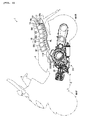
- FIG. 3 shows a hybrid type motorcycle 1 according to this embodiment.
- the hybrid type motorcycle 1 is equipped with a front wheel WHF and a rear wheel WHR, and has a drive unit DY arranged in a lower central portion of a vehicle body 2 formed between the front wheel WHF and the rear wheel WHR, and a high-voltage power unit 10 arranged in a rear portion of the vehicle body 2 above the rear wheel WHR.
- a pair of handlebars 3 equipped with an accelerator grip and a brake (not shown) are provided in an upper front-side portion of the vehicle body 2, and a seat 4 is provided in the portion from an upper central portion of the vehicle body 2 to a rear portion thereof.
- the drive unit DY includes an electric motor 20, an engine 30, a power distributor 25, and a generator 40.
- the hybrid type motorcycle 1 is configured as a series/parallel hybrid type motorcycle in which the engine 30 and the electric motor 20 are used individually as power sources or used in combination to drive the rear wheel WHR that is a drive wheel.
- FIG. 1 is a block diagram showing the power supply control system for the entire vehicle equipped with the motorcycle power supply.
- the motorcycle 1 includes the high-voltage power unit 10 serving as the power source for the electric motor 20, the electric motor 20 that is activated with the high-voltage power unit 10 as the power source to drive the drive wheel WHR, the engine 30 that includes an internal combustion engine and drives the drive wheel WHR, the generator 40 that is rotationally driven by the engine 30 to generate electric power, a hybrid controller 50 for controlling the activations of the electric motor 20, generator 40, and engine 30, a three-level inverter 60 for converting direct-current high-voltage power into alternating-current power on the basis of a control signal from the hybrid controller 50 to thereby supply three-phase power to the electric motor 20, a three-level converter 70 that converts the electric power generated by the generator 40 from an alternating current to a direct current on the basis of a control signal from the hybrid controller 50, a coordination controller 80 for controlling the entire vehicle system, a low-voltage auxiliary battery 100 (hereinafter, simply referred to as "low-voltage battery 100”) with a rated voltage of 12V for supplying power to
- the hybrid controller 50, the inverter 60, the converter 70, and the DC-DC converter 90 are accommodated in an electrical box 110.
- the power distributor 25 distributes the drive force generated by the engine 30 into a drive force for driving the rear wheel WHR and a drive force for driving the generator 40, and also combines the drive force due to the engine 30 and the drive force due to the electric motor 20 into the drive force for driving the rear wheel WHR.
- the power distributor 25 is composed of, for example, a planetary gear mechanism.
- the high-voltage power unit 10 includes six battery modules B1, B2, B3, B4, B5, B6.
- battery module B the battery modules B1, B2, B3, B4, B5, B6 will be generically referred to simply as battery module B.
- This battery module B corresponds to the battery according to the present teaching.
- the high-voltage power unit 10 includes a power output terminal strip 17 for connecting the distribution cable for supplying power.
- the power output terminal strip 17 includes three connection terminals composed of a positive power output terminal TP, a negative power output terminal TN, and a neutral terminal TC.
- the six battery modules B1, B2, B3, B4, B5, B6 are connected in series.
- the plus-side end of the row of serially connected batteries (the plus electrode of the battery module B1) is connected to the positive power output terminal TP, and the minus-side end of the row of serially connected batteries (the minus electrode of the battery module B6) is connected to the negative power output terminal TN.
- the intermediate point of the six battery modules B1 to B6 connected in series that is, the connecting point between the minus electrode of the battery module B3 and the plus electrode of the battery module B4 serves as a neutral point C to be connected to the neutral terminal TC.
- a voltage of + 150V relative to the neutral point C, and a voltage of - 150V relative to the neutral point C, are output to the positive power output terminal TP and negative power output terminal TN of the power output terminal strip 17, respectively.
- a three-wire electric power supply cable HL is connected to the power output terminal strip 17 via an output coupler CP (see FIG. 3).
- This three-wire electric power supply cable corresponds to a three-level power line according to the present teaching.
- the three-wire electric power supply cable HL is referred to as high-voltage power supply line HL.
- the wire connected to the positive power output terminal TP is referred to as high-voltage positive potential line HPL
- the wire connected to the negative power output terminal TN is referred to as high-voltage negative potential line HNL
- neutral line HCL the wire connected to the neutral terminal TC is referred to as neutral line HCL.
- Sub battery management controllers 11, 12, 13, 14, 15 are connected to the battery modules B1. B2, B3, B4, B5, respectively, and a main battery management controller 16 is connected to the battery module B6.
- Each of the sub battery management controllers 11, 12, 13, 14, 15 detects the charge status from the charge/discharge capacity, the temperature, and the like in each of the battery modules B1, B2, B3, B4, B5, and transmits the charge status data to the main battery management controller 16.
- the main battery management controller 16 detects the charge status in the battery module B6, and transmits the charge status data to the coordination controller 80 together with the charge status data transmitted from the sub battery management controllers 11, 12, 13, 14, 15.
- the high-voltage power unit 10 configured as described above is installed in the rear portion of the vehicle body 2 above the rear wheel WHR.
- the battery modules B are arranged in a row along the longitudinal direction of the vehicle, with a safety plug device 19 and the power output terminal strip 17 provided in rear thereof.
- the safety plus device 19 which is omitted in FIG. 1, is used to perform the serial connection of the six battery modules B at once at one location.
- the safety plus device 19 includes a female electrode strip 19a having a female electrode (not shown) that is electrically connected to the plus electrode terminal and minus electrode terminal of each battery module B.
- the six battery modules B are serially connected by inserting a male electrode plug 19b into the female electrode strip 19a, and the serial connection of all the battery modules B is cut off by detaching the male electrode plug 19b.
- the plus electrode terminal of the battery module B1 Connected to the power output terminal strip 17 via the safety plug device 19 are the plus electrode terminal of the battery module B1, the minus electrode terminal of the battery module B6, and the connecting point (neutral point C) between the battery module B3 and the battery module B4.
- the high-voltage power supply line HL is provided with a system main relay 18.
- the coordination controller 80 carries out a diagnosis of the vehicle control system, and when the use of the high-voltage power unit 10 is permitted as a result of this diagnosis, the contact of the system main relay 18 turns on. This contact of the system main relay 18 is provided in each of the high-voltage positive potential line HPL and the high-voltage negative potential line HNL in the high-voltage power supply line HL.
- Three smoothing capacitors C1, C2, C3 are provided in the high-voltage power supply line HL between the high-voltage power unit 10 and the inverter 60. That is, the smoothing capacitor C1 is provided between the high-voltage positive potential line HPL and the high-voltage negative potential line HNL, the smoothing capacitor C2 is provided between the high-voltage positive potential line HPL and the neutral line HCL, and the smoothing capacitor C3 is provided between the high-voltage negative potential line HNL and the neutral line HCL.
- a low-voltage battery 100 serves as a power source for auxiliaries such as a lamp, and control units such as the coordination controller 80 and the hybrid controller 50.
- a two-wire low-voltage power supply line LL is connected to a plus power terminal 101 and minus power terminal 102 of the low-voltage battery 100.
- the wire connected to the plus power terminal 101 of the low-voltage battery 100 is referred to as low-voltage positive line LPL, and the wire connected to the minus power terminal 102 thereof is referred to as low-voltage negative line LNL.
- the minus power terminal 102 of the low-voltage battery 100 is not grounded to the vehicle body.
- the DC-DC converter 90 includes three input terminals 91, 92, 93 that are branched and connected from the high-voltage power supply line HL.
- the high-voltage positive potential line HPL, the neutral line HCL, and the high-voltage negative potential line HNL are connected to the input terminals 91, 92, and 93, respectively.
- the DC-DC converter 90 converts each of +150V direct-current voltage between the neutral line HCL and the high-voltage positive potential line HPL, and -150V direct-current voltage between the neutral line HCL and the high-voltage negative potential line HNL into +12V direct-current voltage. For example, after converting direct-current into alternating-current by a transistor bridge circuit, the voltage is lowered by a transformer, followed by passage through a rectifying circuit and a smoothing circuit to thereby obtain more stable direct-current power (these circuits are not shown).
- the DC-DC converter 90 includes output terminals 94, 95 for outputting the direct-current power with the lowered voltage.
- the voltage between the output terminal 94 and the output terminal 95 is 12V.
- the output terminal 94 which is at a higher potential, is connected to the low-voltage positive line LPL of the low-voltage power supply line LL, and the output terminal 95 at a lower potential is connected to the low-voltage negative line LNL of the low-voltage power supply line LL.
- the neutral line HCL of the high-voltage power supply line HL and the low-voltage negative line LNL of the low-voltage power supply line LL are connected to each other. The operation of the DC-DC converter 90 is thus stabilized to achieve high efficiency.
- the neutral line HCL and the low-voltage negative line LNL are not grounded to the vehicle body. This is because if these lines are grounded to the vehicle body, should an electrical leak occur, a person making contact with the vehicle body receives an electric shock.
- the DC-DC converter 90 in order to output a direct-current power source voltage of 12V, when the battery voltage of the low-voltage battery 100 has dropped due to a decrease in its remaining capacity, the low-voltage battery 100 is charged with the output of the DC-DC converter 90. At this time, the DC-DC converter 90 supplies power also to the electrical loads of a low-voltage system.
- the coordination controller 90 and the hybrid controller 50 are connected to the low-voltage power supply line LL.
- the coordination controller 80 is responsible for the coordinated control of the entire vehicle and mainly composed of a microcomputer.
- the coordination controller 80 acquires operation information and vehicle state information acquired from various sensors (not shown), calculates a drive command value for each of the electric motor 20, generator 40, and engine 30, and outputs a control command for the same to the hybrid controller 50, while controlling the actuations of other actuators.
- Examples of information input to the coordination controller 80 include accelerator opening information, ignition switch information, vehicle speed information, cooling-water temperature information, high-voltage-battery voltage information, low-voltage-battery voltage information, fuel injection amount information, and fuel remaining-amount information.
- the coordination controller 80 drives and controls actuators, such as a cooling-water pump and a cooling fan (not shown), and outputs a start/stop command for the voltage-lowering operation of the DC-DC converter 90, an activation command for the battery management controllers 11 to 16, and the like.
- actuators such as a cooling-water pump and a cooling fan (not shown)
- the coordination controller 80, the hybrid controller 50, and the main battery management controller 16 are capable of communicating with each other through CAN (Controller Area Network) communication.
- CAN Controller Area Network
- the coordination controller 80 calculates a torque command value for the electric motor 20, a speed command value and torque command value for the generator 40, and an opening command value for the throttle valve of the engine 30 on the basis of operation information or vehicle state information such as accelerator opening information, and outputs the calculated command values to the hybrid controller 50.
- the hybrid controller 50 is mainly composed of a microcomputer. Directing attention to its functions, the hybrid controller 50 is roughly divided into a motor controlling section 51, a power generation controlling section 52, and an engine controlling section 53.
- the motor controlling section 51 controls the inverter 60 via a gate circuit 61 so that a current corresponding to the torque command value flows in the electric motor 20.
- the electric motor 20 used is a permanent magnet type synchronous motor having a permanent magnet embedded in the rotor, and U, V, and W phase coils provided in the stator at a pitch of 120°.
- the electric motor 20 is provided with a resolver 21 for detecting the rotation angle thereof. Further, current sensors 22, 23 for detecting a current value are provided in the power supply line for the electric motor 20.
- the motor controlling section 51 On the basis of rotation angle information from the resolver 21 and current value information from the current sensors 22, 23, the motor controlling section 51 performs PWM control on each switching element (which will be described later) of the gate circuit 61 at a duty ratio corresponding to the torque command value.
- the power generation controlling section 52 controls the converter 70 via a gate circuit 71 on the basis of a speed command value and a generator torque command value that are input from the coordination controller 80, thereby adjusting the amount of power generation by the generator 40 that is driven by the engine 30.
- a permanent magnet type synchronous motor similar to the electric motor 20 is used for the generator 40.
- the generator 40 is used not only for generating electric power but also as a rotational drive source (electric motor).
- the generator 40 is provided with a resolver 41 for detecting the rotation angle thereof.
- Current sensors 42, 43 for detecting a current value are provided in the electric power output line for the generator 40.
- the power generation controlling section 52 performs PWM control on each switching element (which will be described later) of the gate circuit 71 at a duty ratio corresponding to the torque command value and the speed command value.
- the engine controlling section 53 acquires detection information from sensors, such as a throttle opening sensor 111, a crank angle sensor 112, a front wheel speed sensor 113, a rear wheel speed sensor 114, an intake pressure sensor 115, an intake temperature sensor 116, and a cooling-water temperature sensor 117. Further, the engine controlling section 53 drives and controls actuators, such as a throttle opening adjusting motor 31, an injector 32, an ignition coil 33, and a fuel pump 34, on the basis of the throttle opening command input from the coordination controller 80.
- actuators such as a throttle opening adjusting motor 31, an injector 32, an ignition coil 33, and a fuel pump 34
- the inverter 60 is a three-level inverter for converting three-level-potential direct-current power supplied from the high-voltage power supply line HL into three-phase alternating-current power.
- the inverter 60 is controlled so that a three-phase alternating-current voltage corresponding to the drive command value from the hybrid controller 50 is output to the electric motor 20.
- the inverter 60 includes three switching rows (a U-phase switching row SMU, a V-phase switching row SMV, and a W-phase switching row SMW) arranged in parallel between the high-voltage positive potential line HPL and the high-voltage negative potential line HNL.
- three switching rows a U-phase switching row SMU, a V-phase switching row SMV, and a W-phase switching row SMW
- the U-phase switching row SMU is composed of switching elements S1U, S2U, S3U, S4U that are connected in series, and diodes D1 U, D2U, D3U, D4U that are connected in inverse-parallel to the respective switching elements S1U, S2U, S3U, S4U.
- the connecting point between the emitter of the switching element S2U and the collector of the switching element S3U is connected to the U phase of the electric motor 20.
- the neutral line HCL is connected to the connecting point between the emitter of the switching element S1U and the collector of the switching element S2U.
- a diode D12U is provided with the cathode facing toward the switching element S1U.
- the high-voltage negative potential line HNL is connected to the connecting point between the emitter of the switching element S3U and the collector of the switching element S4U.
- a diode D34U is provided with the cathode facing toward the switching element S3U.
- V-phase switching row SMV and the W-phase switching row SMW are of the same circuit configuration as the U-phase switching row SMU, in FIG. 2, the respective elements are denoted by the same symbols (except the last character of each symbol; the last character of each symbol indicates the kind of the switching row) and description thereof is not repeated.
- the connecting point between the emitter of the switching element S2V and the collector of the switching element S3V is connected to the V phase of the electric motor 20
- the connecting point between the emitter of the switching element S2W and the collector of the switching element S3W is connected to the W phase of the electric motor 20.
- an FET or IGBT is used as each of the switching elements S1U to S4U, S1V to S4V, S1W to S4W, for example.
- Each of the switching elements S1U to S4U, S1V to S4V, S1W to S4W are on/off controlled with a shift of 120° between the phases, on the basis of a pulse signal output from the gate circuit 61. Accordingly, the inverter 60 converts direct-current power supplied from the high-voltage power supply line HL into three-phase alternating-current power for output to the electric motor 20.
- the output voltage to the U phase of the electric motor 20 can be set to +150V by turning the switching elements S1U, S2U on and the switching elements S3U, S4U off, and set to 0V by turning the switching elements S2U, S3U on and the switching elements S1U, S4U off, as well as set to -150V by turning the switching elements S3, S4 on and the switching elements S1U, S2U off.
- three levels of voltages: positive, negative, and zero can be output to the U, V, W phases of the electric motor 20 by switching the on/off of each of the switching elements S1U to S4U, S1V to S4V, S1W to S4W.
- the motor controlling section 51 adjusts the output voltage through PWM control, that is, by controlling the on/off time ratio (duty ratio) of each of the switching elements S1U to S4U, S1V to S4V, S1W to S4W, thereby creating three-phase alternating-current power.
- three-phase alternating-current power can be created by setting the on-time of PWM control on the basis of a comparison (size relationship) between a target voltage sine waveform corresponding to a torque command value and a preset carrier waveform (delta wave), and by providing a phase shift of 120° between the U, V, W phases.
- the motor controlling section 51 computes a current command value (id, iq) in the d-q coordinate system corresponding to the torque command value, and coordinate-converts the three-phase current value detected by the current sensors 22, 23 into a two-phase current value (idx, iqx) on the basis of the rotation angle detected by the resolver 21.
- target drive voltages for the three phases of the electric motor 20 are calculated, and the respective switching elements S1U to S4U, S1V to S4V, S1W to S4W are on/off controlled at duty ratios corresponding to the voltages.
- the inverter 60 even in the case of a configuration in which alternating-current power of a high voltage of 300V in terms of amplitude value is supplied to the electric motor 20, as the direct-current input power, only half the voltage, +150V and -150V relative to the neutral point C, suffices.
- the converter 70 is a three-level converter that converts the three-phase alternating-current electric power generated by the generator 40 into three-level direct-current electric power, and controls the amount of power generation in accordance with the speed (rpm) command value and torque command value from the hybrid controller 50.
- the converter 70 is provided in parallel to the inverter 60 with respect to the high-voltage power supply line HL, and includes three switching rows (a U-phase switching row SGU, a V-phase switching row SGV, and a W-phase switching row SGW) arranged in parallel between the high-voltage positive potential line HPL and the high-voltage negative potential line HNL.
- three switching rows a U-phase switching row SGU, a V-phase switching row SGV, and a W-phase switching row SGW
- the U-phase switching row SGU is composed of switching elements S5U, S6U, S7U, S8U that are connected in series, and diodes D5U, D6U, D7U, and D8U that are connected in inverse-parallel to the respective switching elements S5U, S6U, S7U, S8U.
- the connecting point between the emitter of the switching element S6U and the collector of the switching element S7U is connected to the U phase of the generator 40.
- the neutral line HCL is connected to the connecting point between the emitter of the switching element S5U and the collector of the switching element S6U.
- a diode D56U is provided with the cathode facing toward the switching element S5U.
- the high-voltage negative potential line HNL is connected to the connecting point between the emitter of the switching element S7U and the collector of the switching element S8U.
- a diode D78U is provided with the cathode facing toward the switching element S7U.
- V-phase switching row SGV and the W-phase switching row SGW are of the same circuit configuration as the U-phase switching row SGU, in FIG. 2, the respective elements are denoted by the same symbols (except the last character of each symbol; the last character of each symbol indicates the kind of the switching row) and description thereof is not repeated.
- the connecting point between the emitter of the switching element S6V and the collector of the switching element S7V is connected to the V phase of the generator 40
- the connecting point between the emitter of the switching element S6W and the collector of the switching element S7W is connected to the W phase of the generator 40.
- each of the switching elements S5U to S8U, S5V to S8V, S5W to S8W is on/off controlled in synchronization with the rotation angle of the generator 40 by means of a pulse signal output from the gate circuit 71, thereby converting the three-phase alternating-current electric power generated by the generator 40 into three-level-potential direct-current electric power.
- the conversion of the three level potentials may be effected by the on/off control of each of the switching elements S5U to S8U, S5V to S8V, S5W to S8W in the same manner as in the inverter 60.
- the output of the converter 70 is connected to the high-voltage power supply line HL.
- the battery modules B of the high-voltage power unit 10 are charged due to the potential difference between the output of the converter 70 and the high-voltage power supply line HL. Accordingly, as for the output of the converter 70, the output voltage to the high-voltage positive potential line HPL with respect to the neutral point C is set higher than +150V, and the output voltage to the high-voltage negative potential line HNL is set lower than -150V.
- the power generation controlling section 52 of the hybrid controller 50 adjusts the direct-current output voltage through PWM control, that is, by controlling the duty ratio of each of the switching elements S5U to S8U, S5V to S8V, S5W to S8W.
- PWM control is performed in the same manner as in the motor controlling section 51; the output voltage is controlled to a target voltage corresponding to the torque command value and the speed command value, on the basis of the current value detected by the current sensors 42, 43 and the rotation angle detected by the resolver 41.
- the converter 70 as described above, the three-phase alternating-current electric power generated by the generator 40 is converted into three-level-potential direct-current electric power, thereby making it possible to charge each battery module B of the high-voltage power unit 10 via the high-voltage power supply line HL. Further, this can also be used as a power source for the electric motor 20. Furthermore, the converter 70 may be made to function as an inverter to rotate the generator 40 like the electric motor 20, thereby effecting the starting of the engine 30, or the like.
- the inverter 60 and the converter 70 as described above are each equipped with a radiator (not shown), with radiator-cooling water circulated inside this radiator to thereby effect cooling. Further, the electric motor 20 and the generator 40 may also be cooled with cooling water flowing in a common circulation path.
- the power supply of this embodiment with the intermediate connecting point of the serially connected battery modules B serving as the electrical neutral point C, high-voltage power is supplied by means of the three-level-potential high-voltage power supply line using this neutral point C. Accordingly, the withstand voltage required of the control units or control elements (such as the DC-DC converter 90, the system main relay 18, the capacitors C1 to C3, the inverter 60, and the converter 70) can be halved.
- the control units or control elements such as the DC-DC converter 90, the system main relay 18, the capacitors C1 to C3, the inverter 60, and the converter 70
- the power supply system proves effective particularly when applied to a hybrid type motorcycle with a narrow installation space. Further, the limitations on the withstand-voltage performance of the control units or control elements are reduced, thereby increasing the freedom of design.
- the battery modules B of the high-voltage power unit 10 can be charged via the high-voltage power supply line HL.
- the high-voltage power source voltage supplied from the high-voltage power supply line HL is lowered by the DC-DC converter 90 and then output to the low-voltage power supply line LL, it is possible to charge the low-voltage battery 100 and thus keep the low-voltage battery 100 in a favorable state.
- the foregoing description is directed to the power supply applied to a hybrid type motorcycle
- the present invention may be applied not only to a motorcycle or also to a four-wheeled car or the like, or to an electric car not equipped with an engine.
- the power supply is equipped with the DC-DC converter 90 as a back up for the low-voltage power source, such a structure may be omitted.
- two kinds of power source voltage at the potentials of +150V and -150V relative to the neutral line HCL are used in the DC-DC converter 90, it is also possible to use either one of the power source voltages (+150V or -150V).
- the power supply system from the high-voltage power unit 10 to the inverter 60 corresponds to the power supply according to the present teaching. Further, it is also possible to construct the power supply according to the present teaching so as to include also the converter 70, the DC-DC converter 90, the low-voltage battery 100, and the low-voltage power supply line LL.
- a power supply for an electric vehicle in which a plurality of batteries are serially connected, and a high voltage obtained by the serially connected batteries is supplied as a power source to a vehicle-driving electric motor, including: a three-level power line that forms a direct-current power supply line including, with an intermediate connection position of the serially connected batteries serving as a neutral point, a neutral line connected to the neutral point, a positive potential line connected to a plus-side end of a row of the serially connected batteries, and a negative potential line connected to a minus-side end of the row of the serially connected batteries; and a three-level inverter for converting direct-current power supplied from the three-level power line into alternating-current power for supply to the electric motor.
- the power supply includes the neutral line connected to the intermediate connection position of the row of serially connected batteries, and this neutral line is combined with the positive potential line, which is at a high potential relative to the neutral line, and the negative potential line, which is at a negative potential relative to the neutral line, to form a power line for supplying power to the three-level inverter. Accordingly, with respect to the requisite voltage for driving the electric motor, the voltage to be applied between the neutral line and the positive voltage line, and the voltage to be applied between the neutral line and the negative voltage line, can be halved.
- the electric vehicle is a hybrid type vehicle including a generator that is driven by an internal combustion engine to generate electric power, and the power supply further includes a three-level converter for converting an alternating-current output of the generator into a three-level-potential direct-current voltage for supply to the three-level power line.
- the three-level power line can also be used to charge the batteries with the electric power generated from the generator.
- the power supply further includes: a low-voltage auxiliary battery that is different from the batteries for supplying power to the three-level power line; and a DC-DC converter for converting a power source voltage supplied to the three-level power line into a rated voltage of the low-voltage auxiliary battery, in which an output of the DC-DC converter is connected to a power supply line for the low-voltage auxiliary battery, and a negative-side line in the power supply line for the low-voltage auxiliary battery and the neutral line of the three-level power line are connected to each other.
- the high-voltage-battery power source voltage is lowered by the DC-DC converter to the rated voltage (for example, 12V) of the low-voltage auxiliary battery and then supplied to the power supply line for the low-voltage auxiliary battery. Accordingly, even when the capacity of the low-voltage auxiliary battery has dropped, this can be backed up by the high-voltage batteries (serially connected batteries).
- a power supply for an electric vehicle in which a plurality of batteries are serially connected, and a high voltage obtained by the serially connected batteries is supplied as a power source to a vehicle-driving electric motor, comprising: a three-level power line that forms a direct-current power supply line including, with an intermediate connection position of the serially connected batteries serving as a neutral point, a neutral line connected to the neutral point, a positive potential line connected to a plus-side end of a row of the serially connected batteries, and a negative potential line connected to a minus-side end of the row of the serially connected batteries; and a three-level inverter for converting direct-current power supplied from the three-level power line into alternating-current power for supply to the electric motor.
- the electric vehicle is a hybrid type vehicle including a generator that is driven by an internal combustion engine to generate electric power; and the power supply further comprises a three-level converter for converting an alternating-current output of the generator into a three-level-potential direct-current voltage for supply to the three-level power line.
- the power supply for an electric vehicle further comprises: a low-voltage auxiliary battery that is different from the batteries for supplying power to the three-level power line; and a DC-DC converter for converting a power source voltage supplied to the three-level power line into a rated voltage of the low-voltage auxiliary battery, wherein an output of the DC-DC converter is connected to a power supply line for the low-voltage auxiliary battery, and a negative-side line in the power supply line for the low-voltage auxiliary battery and the neutral line of the three-level power line are connected to each other.
- an embodiment comprising a plurality of battery modules B are connected in series.
- power is supplied to a three-level inverter 60 by means of a three-level-potential high-voltage power supply line HL having potentials of +150V and -150V relative to this neutral point C.
- direct-current electric power is converted into three-phase alternating-current electric power to drive an electric motor 20.
- the withstand-voltage performance required of control units or control elements connected to the high-voltage power supply line HL can be halved as compared with the related art, thereby allowing a reduction in the size, weight, and cost of the power supply system.
- the electric power generated by a generator 40 is converted into direct-current electric power by a three-level converter 70 and supplied to the high-voltage power supply line HL, thereby charging the battery modules B.
Landscapes
- Engineering & Computer Science (AREA)
- Transportation (AREA)
- Mechanical Engineering (AREA)
- Power Engineering (AREA)
- Chemical & Material Sciences (AREA)
- Combustion & Propulsion (AREA)
- Life Sciences & Earth Sciences (AREA)
- Sustainable Development (AREA)
- Sustainable Energy (AREA)
- Electric Propulsion And Braking For Vehicles (AREA)
- Charge And Discharge Circuits For Batteries Or The Like (AREA)
- Secondary Cells (AREA)
- Hybrid Electric Vehicles (AREA)
Abstract
Description
- The present invention relates to a power supply device, and in particular to a power supply for supplying high-voltage power to a drive electric motor provided to a hybrid car or an electric car.
- Conventionally, in an effort to conserve the global environment, an electrical car that is driven by driving an electric motor using electric power of a battery, a hybrid car that is driven by the combination of a gasoline engine and an electric motor, and the like have been developed. In these electric vehicles, as disclosed in, for example,
Patent Document 1, a high-voltage battery (36V) is provided separately from an ordinary low-voltage battery (12V), and the electric motor is driven by this high-voltage battery. - Recently, in order to drive the electric motor efficiently with high output, the voltage of power source battery units is becoming increasingly higher, leading to the adoption of vehicle power supplies in which a plurality of batteries are connected in series to supply high-voltage power on the order of, for example, 300V or 500V.
- Patent Document 1:
JP-A-2005-98251 - However, such an increase in power source voltage leads to a corresponding increase in the withstand-voltage performance required of control units or control elements within the power supply system. The power supply system thus becomes large-scale in structure. In other words, the size, weight, and cost of the power supply system increases. Further, the freedom of design is reduced.
- The present invention has been made to address the above-mentioned problems, and accordingly it is an object of the present invention to provide a compact, lightweight, and low-cost power supply device, in particular for supplying high-voltage power.
- This objective is solved in an inventive manner by a power supply device for an electric vehicle, comprising a plurality of serially connected batteries and/or battery modules, wherein a plus-side end of the serially connected batteries and/or battery modules is connected to a positive power output terminal, wherein a minus-side end of the serially connected batteries and/or battery modules is connected to a negative power output terminal, and wherein an intermediate point of the circuit serially connecting the batteries and/or battery modules is connected to a neutral terminal.
- Preferably, a high voltage obtained by the serially connected batteries is supplied as a power source to a vehicle-driving electric motor, by a three-level power line that forms a direct-current power supply line including, with an intermediate connection position of the serially connected batteries serving as a neutral point, a neutral line connected to the neutral point, a positive potential line connected to a plus-side end of a row of the serially connected batteries, and a negative potential line connected to a minus-side end of the row of the serially connected batteries.
- According to a preferred embodiment, the power supply device further comprises a three-level inverter for converting direct-current power supplied from the three-level power line into alternating-current power for supply to the electric motor.
- Preferably, the electric vehicle is a hybrid type vehicle including a generator that is driven by an internal combustion engine to generate electric power; and the power supply further comprises a three-level converter for converting an alternating-current output of the generator into a three-level-potential direct-current voltage for supply to the three-level power line.
- According to a further preferred embodiment, the power supply device further comprises a low-voltage auxiliary battery that is different from the batteries and/or battery modules for supplying power to the three-level power line; and a DC-DC converter for converting a power source voltage supplied to the three-level power line into a rated voltage of the low-voltage auxiliary battery, wherein an output of the DC-DC converter is connected to a power supply line for the low-voltage auxiliary battery, and a negative-side line in the power supply line for the low-voltage auxiliary battery and the neutral line of the three-level power line are connected to each other.
- In the following, the present invention is explained in greater detail with respect to several embodiments thereof in conjunction with the accompanying drawings, wherein:
- FIG. 1
- is a block diagram showing a power supply control system for a hybrid type motorcycle according to an embodiment,
- FIG. 2
- is an electrical circuit diagram of an inverter and a converter according to the embodiment, and
- FIG. 3
- is a view illustrating the hybrid type motorcycle according to the embodiment.
-
- 10: high-voltage power unit
- 20: electric motor
- 25: power distributor
- 30: engine
- 40: generator
- 50: hybrid controller
- 60: safety plug
- 80: coordination controller
- 90: DC-DC converter
- 100: low-volage battery
- HL: high-voltage power supply line
- HPL: high-voltage positive potential line
- HNL: high-voltage negative potential line
- HCL: neutral line
- LL: low-voltage power supply line
- LPL: low-voltage positive line
- LPN: low-voltage negative line
- A power supply for an electric vehicle according to an embodiment will be described below with reference to the drawings. In this embodiment, the present teaching is applied to a hybrid type motorcycle.
- FIG. 3 shows a
hybrid type motorcycle 1 according to this embodiment. Thehybrid type motorcycle 1 is equipped with a front wheel WHF and a rear wheel WHR, and has a drive unit DY arranged in a lower central portion of avehicle body 2 formed between the front wheel WHF and the rear wheel WHR, and a high-voltage power unit 10 arranged in a rear portion of thevehicle body 2 above the rear wheel WHR. Further, a pair ofhandlebars 3 equipped with an accelerator grip and a brake (not shown) are provided in an upper front-side portion of thevehicle body 2, and a seat 4 is provided in the portion from an upper central portion of thevehicle body 2 to a rear portion thereof. - The drive unit DY includes an
electric motor 20, anengine 30, apower distributor 25, and agenerator 40. Thehybrid type motorcycle 1 is configured as a series/parallel hybrid type motorcycle in which theengine 30 and theelectric motor 20 are used individually as power sources or used in combination to drive the rear wheel WHR that is a drive wheel. - Since the
electric motor 20, thepower distributor 25, and thegenerator 40 are arranged side by side in the vehicle width direction in rear of theengine 30, only theelectric motor 20 is shown in FIG. 3. - Next, a power supply for the hybrid type motorcycle 1 (hereinafter, simply referred to as "
motorcycle 1 ") will be described with reference to FIG. 1. FIG. 1 is a block diagram showing the power supply control system for the entire vehicle equipped with the motorcycle power supply. - The
motorcycle 1 includes the high-voltage power unit 10 serving as the power source for theelectric motor 20, theelectric motor 20 that is activated with the high-voltage power unit 10 as the power source to drive the drive wheel WHR, theengine 30 that includes an internal combustion engine and drives the drive wheel WHR, thegenerator 40 that is rotationally driven by theengine 30 to generate electric power, ahybrid controller 50 for controlling the activations of theelectric motor 20,generator 40, andengine 30, a three-level inverter 60 for converting direct-current high-voltage power into alternating-current power on the basis of a control signal from thehybrid controller 50 to thereby supply three-phase power to theelectric motor 20, a three-level converter 70 that converts the electric power generated by thegenerator 40 from an alternating current to a direct current on the basis of a control signal from thehybrid controller 50, acoordination controller 80 for controlling the entire vehicle system, a low-voltage auxiliary battery 100 (hereinafter, simply referred to as "low-voltage battery 100") with a rated voltage of 12V for supplying power to electrical loads (referred to as "auxiliaries") of a low-voltage system (12V system), and a DC-DC converter 90 that converts high-voltage power supplied from the high-voltage power unit 10 into low-voltage power of 12V. - The
hybrid controller 50, theinverter 60, theconverter 70, and the DC-DC converter 90 are accommodated in anelectrical box 110. - Further, the
power distributor 25 distributes the drive force generated by theengine 30 into a drive force for driving the rear wheel WHR and a drive force for driving thegenerator 40, and also combines the drive force due to theengine 30 and the drive force due to theelectric motor 20 into the drive force for driving the rear wheel WHR. Thepower distributor 25 is composed of, for example, a planetary gear mechanism. - The high-
voltage power unit 10 includes six battery modules B1, B2, B3, B4, B5, B6. The battery modules B1, B2, B3, B4, B5, B6 are each composed of 14 lithium battery cells (single cell voltage = 3.4V) connected in series and accommodated within a package, and the output voltage thereof is set to 48V. - In the following description, unless individually specified, the battery modules B1, B2, B3, B4, B5, B6 will be generically referred to simply as battery module B. This battery module B corresponds to the battery according to the present teaching.
- The high-
voltage power unit 10 includes a poweroutput terminal strip 17 for connecting the distribution cable for supplying power. The poweroutput terminal strip 17 includes three connection terminals composed of a positive power output terminal TP, a negative power output terminal TN, and a neutral terminal TC. The six battery modules B1, B2, B3, B4, B5, B6 are connected in series. The plus-side end of the row of serially connected batteries (the plus electrode of the battery module B1) is connected to the positive power output terminal TP, and the minus-side end of the row of serially connected batteries (the minus electrode of the battery module B6) is connected to the negative power output terminal TN. Further, the intermediate point of the six battery modules B1 to B6 connected in series, that is, the connecting point between the minus electrode of the battery module B3 and the plus electrode of the battery module B4 serves as a neutral point C to be connected to the neutral terminal TC. - A voltage of + 150V relative to the neutral point C, and a voltage of - 150V relative to the neutral point C, are output to the positive power output terminal TP and negative power output terminal TN of the power
output terminal strip 17, respectively. - Since the voltage of the single cells constituting each of the battery modules B1 to B6 is 3.4V at 80% charge and increases to about 3.6V at full charge, in the following description, it is assumed that the serial voltage of three battery modules B is 150V (3.6 × 14 × 3).
- A three-wire electric power supply cable HL is connected to the power
output terminal strip 17 via an output coupler CP (see FIG. 3). This three-wire electric power supply cable corresponds to a three-level power line according to the present teaching. Hereinafter, the three-wire electric power supply cable HL is referred to as high-voltage power supply line HL. Of the high-voltage power supply line HL, the wire connected to the positive power output terminal TP is referred to as high-voltage positive potential line HPL, the wire connected to the negative power output terminal TN is referred to as high-voltage negative potential line HNL, and the wire connected to the neutral terminal TC is referred to as neutral line HCL. - Sub
battery management controllers battery management controller 16 is connected to the battery module B6. Each of the subbattery management controllers battery management controller 16. The mainbattery management controller 16 detects the charge status in the battery module B6, and transmits the charge status data to thecoordination controller 80 together with the charge status data transmitted from the subbattery management controllers - As shown in FIG. 3, the high-
voltage power unit 10 configured as described above is installed in the rear portion of thevehicle body 2 above the rear wheel WHR. In the high-voltage power unit 10, the battery modules B are arranged in a row along the longitudinal direction of the vehicle, with asafety plug device 19 and the poweroutput terminal strip 17 provided in rear thereof. - The
safety plus device 19, which is omitted in FIG. 1, is used to perform the serial connection of the six battery modules B at once at one location. Thesafety plus device 19 includes afemale electrode strip 19a having a female electrode (not shown) that is electrically connected to the plus electrode terminal and minus electrode terminal of each battery module B. The six battery modules B are serially connected by inserting amale electrode plug 19b into thefemale electrode strip 19a, and the serial connection of all the battery modules B is cut off by detaching themale electrode plug 19b. - Connected to the power
output terminal strip 17 via thesafety plug device 19 are the plus electrode terminal of the battery module B1, the minus electrode terminal of the battery module B6, and the connecting point (neutral point C) between the battery module B3 and the battery module B4. - The high-voltage power supply line HL is provided with a system
main relay 18. Upon turning on an ignition switch (not shown), thecoordination controller 80 carries out a diagnosis of the vehicle control system, and when the use of the high-voltage power unit 10 is permitted as a result of this diagnosis, the contact of the systemmain relay 18 turns on. This contact of the systemmain relay 18 is provided in each of the high-voltage positive potential line HPL and the high-voltage negative potential line HNL in the high-voltage power supply line HL. - Three smoothing capacitors C1, C2, C3 are provided in the high-voltage power supply line HL between the high-
voltage power unit 10 and theinverter 60. That is, the smoothing capacitor C1 is provided between the high-voltage positive potential line HPL and the high-voltage negative potential line HNL, the smoothing capacitor C2 is provided between the high-voltage positive potential line HPL and the neutral line HCL, and the smoothing capacitor C3 is provided between the high-voltage negative potential line HNL and the neutral line HCL. - A low-
voltage battery 100 serves as a power source for auxiliaries such as a lamp, and control units such as thecoordination controller 80 and thehybrid controller 50. A two-wire low-voltage power supply line LL is connected to aplus power terminal 101 andminus power terminal 102 of the low-voltage battery 100. Hereinafter, of the low-voltage power supply line LL, the wire connected to theplus power terminal 101 of the low-voltage battery 100 is referred to as low-voltage positive line LPL, and the wire connected to theminus power terminal 102 thereof is referred to as low-voltage negative line LNL. - The
minus power terminal 102 of the low-voltage battery 100 is not grounded to the vehicle body. - The DC-
DC converter 90 includes threeinput terminals input terminals - The DC-
DC converter 90 converts each of +150V direct-current voltage between the neutral line HCL and the high-voltage positive potential line HPL, and -150V direct-current voltage between the neutral line HCL and the high-voltage negative potential line HNL into +12V direct-current voltage. For example, after converting direct-current into alternating-current by a transistor bridge circuit, the voltage is lowered by a transformer, followed by passage through a rectifying circuit and a smoothing circuit to thereby obtain more stable direct-current power (these circuits are not shown). - The DC-
DC converter 90 includesoutput terminals output terminal 94 and theoutput terminal 95 is 12V. Theoutput terminal 94, which is at a higher potential, is connected to the low-voltage positive line LPL of the low-voltage power supply line LL, and theoutput terminal 95 at a lower potential is connected to the low-voltage negative line LNL of the low-voltage power supply line LL. - Further, inside the DC-
DC converter 90, the neutral line HCL of the high-voltage power supply line HL and the low-voltage negative line LNL of the low-voltage power supply line LL are connected to each other. The operation of the DC-DC converter 90 is thus stabilized to achieve high efficiency. - Further, for safety considerations, the neutral line HCL and the low-voltage negative line LNL are not grounded to the vehicle body. This is because if these lines are grounded to the vehicle body, should an electrical leak occur, a person making contact with the vehicle body receives an electric shock.
- In the DC-
DC converter 90, in order to output a direct-current power source voltage of 12V, when the battery voltage of the low-voltage battery 100 has dropped due to a decrease in its remaining capacity, the low-voltage battery 100 is charged with the output of the DC-DC converter 90. At this time, the DC-DC converter 90 supplies power also to the electrical loads of a low-voltage system. - In addition to the auxiliaries such as a lamp, the
coordination controller 90 and thehybrid controller 50 are connected to the low-voltage power supply line LL. - The
coordination controller 80 is responsible for the coordinated control of the entire vehicle and mainly composed of a microcomputer. Thecoordination controller 80 acquires operation information and vehicle state information acquired from various sensors (not shown), calculates a drive command value for each of theelectric motor 20,generator 40, andengine 30, and outputs a control command for the same to thehybrid controller 50, while controlling the actuations of other actuators. - Examples of information input to the
coordination controller 80 include accelerator opening information, ignition switch information, vehicle speed information, cooling-water temperature information, high-voltage-battery voltage information, low-voltage-battery voltage information, fuel injection amount information, and fuel remaining-amount information. - Further, on the basis of these various information, the
coordination controller 80 drives and controls actuators, such as a cooling-water pump and a cooling fan (not shown), and outputs a start/stop command for the voltage-lowering operation of the DC-DC converter 90, an activation command for the battery management controllers 11 to 16, and the like. - The
coordination controller 80, thehybrid controller 50, and the mainbattery management controller 16 are capable of communicating with each other through CAN (Controller Area Network) communication. - The
coordination controller 80 calculates a torque command value for theelectric motor 20, a speed command value and torque command value for thegenerator 40, and an opening command value for the throttle valve of theengine 30 on the basis of operation information or vehicle state information such as accelerator opening information, and outputs the calculated command values to thehybrid controller 50. - The
hybrid controller 50 is mainly composed of a microcomputer. Directing attention to its functions, thehybrid controller 50 is roughly divided into amotor controlling section 51, a powergeneration controlling section 52, and anengine controlling section 53. - On the basis of a motor torque command value input from the
coordination controller 80, themotor controlling section 51 controls theinverter 60 via agate circuit 61 so that a current corresponding to the torque command value flows in theelectric motor 20. - The
electric motor 20 used is a permanent magnet type synchronous motor having a permanent magnet embedded in the rotor, and U, V, and W phase coils provided in the stator at a pitch of 120°. Theelectric motor 20 is provided with aresolver 21 for detecting the rotation angle thereof. Further,current sensors 22, 23 for detecting a current value are provided in the power supply line for theelectric motor 20. - On the basis of rotation angle information from the
resolver 21 and current value information from thecurrent sensors 22, 23, themotor controlling section 51 performs PWM control on each switching element (which will be described later) of thegate circuit 61 at a duty ratio corresponding to the torque command value. - The power
generation controlling section 52 controls theconverter 70 via agate circuit 71 on the basis of a speed command value and a generator torque command value that are input from thecoordination controller 80, thereby adjusting the amount of power generation by thegenerator 40 that is driven by theengine 30. - A permanent magnet type synchronous motor similar to the
electric motor 20 is used for thegenerator 40. Thegenerator 40 is used not only for generating electric power but also as a rotational drive source (electric motor). - The
generator 40 is provided with aresolver 41 for detecting the rotation angle thereof.Current sensors generator 40. On the basis of rotation angle information from theresolver 41 and current value information from thecurrent sensors generation controlling section 52 performs PWM control on each switching element (which will be described later) of thegate circuit 71 at a duty ratio corresponding to the torque command value and the speed command value. - The
engine controlling section 53 acquires detection information from sensors, such as athrottle opening sensor 111, acrank angle sensor 112, a front wheel speed sensor 113, a rear wheel speed sensor 114, anintake pressure sensor 115, anintake temperature sensor 116, and a cooling-water temperature sensor 117. Further, theengine controlling section 53 drives and controls actuators, such as a throttleopening adjusting motor 31, aninjector 32, anignition coil 33, and afuel pump 34, on the basis of the throttle opening command input from thecoordination controller 80. - The
inverter 60 is a three-level inverter for converting three-level-potential direct-current power supplied from the high-voltage power supply line HL into three-phase alternating-current power. Theinverter 60 is controlled so that a three-phase alternating-current voltage corresponding to the drive command value from thehybrid controller 50 is output to theelectric motor 20. - As shown in FIG. 2, the
inverter 60 includes three switching rows (a U-phase switching row SMU, a V-phase switching row SMV, and a W-phase switching row SMW) arranged in parallel between the high-voltage positive potential line HPL and the high-voltage negative potential line HNL. - The U-phase switching row SMU is composed of switching elements S1U, S2U, S3U, S4U that are connected in series, and diodes D1 U, D2U, D3U, D4U that are connected in inverse-parallel to the respective switching elements S1U, S2U, S3U, S4U. The connecting point between the emitter of the switching element S2U and the collector of the switching element S3U is connected to the U phase of the
electric motor 20. Further, the neutral line HCL is connected to the connecting point between the emitter of the switching element S1U and the collector of the switching element S2U. In the connecting line connecting to the emitter of the switching element S1 U from this neutral line HCL, a diode D12U is provided with the cathode facing toward the switching element S1U. - Further, the high-voltage negative potential line HNL is connected to the connecting point between the emitter of the switching element S3U and the collector of the switching element S4U. In the connecting line connecting to the emitter of the switching element S3U from this high-voltage negative potential line HNL, a diode D34U is provided with the cathode facing toward the switching element S3U.
- Since the V-phase switching row SMV and the W-phase switching row SMW are of the same circuit configuration as the U-phase switching row SMU, in FIG. 2, the respective elements are denoted by the same symbols (except the last character of each symbol; the last character of each symbol indicates the kind of the switching row) and description thereof is not repeated.
- In the V-phase switching row SMV, the connecting point between the emitter of the switching element S2V and the collector of the switching element S3V is connected to the V phase of the
electric motor 20, and in the W-phase switching row SMW, the connecting point between the emitter of the switching element S2W and the collector of the switching element S3W is connected to the W phase of theelectric motor 20. - Further, an FET or IGBT is used as each of the switching elements S1U to S4U, S1V to S4V, S1W to S4W, for example.
- Each of the switching elements S1U to S4U, S1V to S4V, S1W to S4W are on/off controlled with a shift of 120° between the phases, on the basis of a pulse signal output from the
gate circuit 61. Accordingly, theinverter 60 converts direct-current power supplied from the high-voltage power supply line HL into three-phase alternating-current power for output to theelectric motor 20. - Description will be given of the U-phase switching row SMU, for example. The output voltage to the U phase of the
electric motor 20 can be set to +150V by turning the switching elements S1U, S2U on and the switching elements S3U, S4U off, and set to 0V by turning the switching elements S2U, S3U on and the switching elements S1U, S4U off, as well as set to -150V by turning the switching elements S3, S4 on and the switching elements S1U, S2U off. The same applies to the other switching rows SMV, SMW. Accordingly, three levels of voltages: positive, negative, and zero, can be output to the U, V, W phases of theelectric motor 20 by switching the on/off of each of the switching elements S1U to S4U, S1V to S4V, S1W to S4W. - At this time, the
motor controlling section 51 adjusts the output voltage through PWM control, that is, by controlling the on/off time ratio (duty ratio) of each of the switching elements S1U to S4U, S1V to S4V, S1W to S4W, thereby creating three-phase alternating-current power. - For example, three-phase alternating-current power can be created by setting the on-time of PWM control on the basis of a comparison (size relationship) between a target voltage sine waveform corresponding to a torque command value and a preset carrier waveform (delta wave), and by providing a phase shift of 120° between the U, V, W phases.
- Further, in controlling the
electric motor 20, themotor controlling section 51 computes a current command value (id, iq) in the d-q coordinate system corresponding to the torque command value, and coordinate-converts the three-phase current value detected by thecurrent sensors 22, 23 into a two-phase current value (idx, iqx) on the basis of the rotation angle detected by theresolver 21. Then, on the basis of the deviation between this two-phase current value (idx, iqx) and the current command value (id, iq), target drive voltages for the three phases of theelectric motor 20 are calculated, and the respective switching elements S1U to S4U, S1V to S4V, S1W to S4W are on/off controlled at duty ratios corresponding to the voltages. - According to the
inverter 60 as described above, even in the case of a configuration in which alternating-current power of a high voltage of 300V in terms of amplitude value is supplied to theelectric motor 20, as the direct-current input power, only half the voltage, +150V and -150V relative to the neutral point C, suffices. - Accordingly, even when the voltage of the power unit in the hybrid vehicle is increased, high withstand-voltage performance is not required of the control elements or control units, and it suffices to satisfy a withstand voltage of 150V. It is thus possible to achieve a reduction in the size, weight, and cost of the power supply system. Further, the freedom of design can be also increased.
- In contrast, in the case of the high-voltage power supply of the related art, when driving the electric motor at the same voltage of 300V (amplitude value), due to the use of a two-wire power supply line of 0V - 300V, high withstand-voltage performance (300V) is required of the control units or control elements connected to that power supply line.
- The
converter 70 is a three-level converter that converts the three-phase alternating-current electric power generated by thegenerator 40 into three-level direct-current electric power, and controls the amount of power generation in accordance with the speed (rpm) command value and torque command value from thehybrid controller 50. - As shown in FIG. 2, the
converter 70 is provided in parallel to theinverter 60 with respect to the high-voltage power supply line HL, and includes three switching rows (a U-phase switching row SGU, a V-phase switching row SGV, and a W-phase switching row SGW) arranged in parallel between the high-voltage positive potential line HPL and the high-voltage negative potential line HNL. - The U-phase switching row SGU is composed of switching elements S5U, S6U, S7U, S8U that are connected in series, and diodes D5U, D6U, D7U, and D8U that are connected in inverse-parallel to the respective switching elements S5U, S6U, S7U, S8U. The connecting point between the emitter of the switching element S6U and the collector of the switching element S7U is connected to the U phase of the
generator 40. Further, the neutral line HCL is connected to the connecting point between the emitter of the switching element S5U and the collector of the switching element S6U. In the connecting line connecting to the emitter of the switching element S5U from this neutral line HCL, a diode D56U is provided with the cathode facing toward the switching element S5U. - Further, the high-voltage negative potential line HNL is connected to the connecting point between the emitter of the switching element S7U and the collector of the switching element S8U. In the connecting line connecting to the emitter of the switching element S7U from this high-voltage negative potential line HNL, a diode D78U is provided with the cathode facing toward the switching element S7U.
- Since the V-phase switching row SGV and the W-phase switching row SGW are of the same circuit configuration as the U-phase switching row SGU, in FIG. 2, the respective elements are denoted by the same symbols (except the last character of each symbol; the last character of each symbol indicates the kind of the switching row) and description thereof is not repeated.
- In the V-phase switching row SGV, the connecting point between the emitter of the switching element S6V and the collector of the switching element S7V is connected to the V phase of the
generator 40, and in the W-phase switching row SGW, the connecting point between the emitter of the switching element S6W and the collector of the switching element S7W is connected to the W phase of thegenerator 40. - In the
generator 40, the rotor is rotated as the rotary force is transmitted from theengine 30 by thepower distributor 25, thereby generating three-phase alternating-current power due to a counter electromotive force. Then, in theconverter 70, each of the switching elements S5U to S8U, S5V to S8V, S5W to S8W is on/off controlled in synchronization with the rotation angle of thegenerator 40 by means of a pulse signal output from thegate circuit 71, thereby converting the three-phase alternating-current electric power generated by thegenerator 40 into three-level-potential direct-current electric power. The conversion of the three level potentials may be effected by the on/off control of each of the switching elements S5U to S8U, S5V to S8V, S5W to S8W in the same manner as in theinverter 60. - The output of the
converter 70 is connected to the high-voltage power supply line HL. In this case, the battery modules B of the high-voltage power unit 10 are charged due to the potential difference between the output of theconverter 70 and the high-voltage power supply line HL. Accordingly, as for the output of theconverter 70, the output voltage to the high-voltage positive potential line HPL with respect to the neutral point C is set higher than +150V, and the output voltage to the high-voltage negative potential line HNL is set lower than -150V. - The power
generation controlling section 52 of thehybrid controller 50 adjusts the direct-current output voltage through PWM control, that is, by controlling the duty ratio of each of the switching elements S5U to S8U, S5V to S8V, S5W to S8W. This PWN control is performed in the same manner as in themotor controlling section 51; the output voltage is controlled to a target voltage corresponding to the torque command value and the speed command value, on the basis of the current value detected by thecurrent sensors resolver 41. - According to the
converter 70 as described above, the three-phase alternating-current electric power generated by thegenerator 40 is converted into three-level-potential direct-current electric power, thereby making it possible to charge each battery module B of the high-voltage power unit 10 via the high-voltage power supply line HL. Further, this can also be used as a power source for theelectric motor 20. Furthermore, theconverter 70 may be made to function as an inverter to rotate thegenerator 40 like theelectric motor 20, thereby effecting the starting of theengine 30, or the like. - The
inverter 60 and theconverter 70 as described above are each equipped with a radiator (not shown), with radiator-cooling water circulated inside this radiator to thereby effect cooling. Further, theelectric motor 20 and thegenerator 40 may also be cooled with cooling water flowing in a common circulation path. - As has been described above, according to the power supply of this embodiment, with the intermediate connecting point of the serially connected battery modules B serving as the electrical neutral point C, high-voltage power is supplied by means of the three-level-potential high-voltage power supply line using this neutral point C. Accordingly, the withstand voltage required of the control units or control elements (such as the DC-
DC converter 90, the systemmain relay 18, the capacitors C1 to C3, theinverter 60, and the converter 70) can be halved. - As a result, it is possible to achieve a reduction in the size, weight, and cost of the power supply system. Accordingly, the power supply system proves effective particularly when applied to a hybrid type motorcycle with a narrow installation space. Further, the limitations on the withstand-voltage performance of the control units or control elements are reduced, thereby increasing the freedom of design.
- Further, since the generated alternating-current electric power is converted into direct-current electric power by the three-
level converter 70, the battery modules B of the high-voltage power unit 10 can be charged via the high-voltage power supply line HL. - Further, since the high-voltage power source voltage supplied from the high-voltage power supply line HL is lowered by the DC-
DC converter 90 and then output to the low-voltage power supply line LL, it is possible to charge the low-voltage battery 100 and thus keep the low-voltage battery 100 in a favorable state. - In addition, since the low-voltage negative line LNL in the low-voltage power supply line LL and the neutral line HCL in the high-voltage power supply line HL are connected to each other, the operation of the DC-
DC converter 90 becomes stable and high efficiency can be attained. - While the power supply for an electric vehicle according to this embodiment has been described, the present teaching is not limited to the above-mentioned embodiment, and various modifications can be made without departing from the object of the present teaching.
- For example, while in this embodiment, the foregoing description is directed to the power supply applied to a hybrid type motorcycle, the present invention may be applied not only to a motorcycle or also to a four-wheeled car or the like, or to an electric car not equipped with an engine.
- Further, while in this embodiment, the power supply is equipped with the DC-
DC converter 90 as a back up for the low-voltage power source, such a structure may be omitted. Further, while two kinds of power source voltage at the potentials of +150V and -150V relative to the neutral line HCL are used in the DC-DC converter 90, it is also possible to use either one of the power source voltages (+150V or -150V). - The power supply system from the high-
voltage power unit 10 to theinverter 60 corresponds to the power supply according to the present teaching. Further, it is also possible to construct the power supply according to the present teaching so as to include also theconverter 70, the DC-DC converter 90, the low-voltage battery 100, and the low-voltage power supply line LL. - To achieve the above-mentioned object, according to a preferred aspect of the present teaching, there is provided a power supply for an electric vehicle, in which a plurality of batteries are serially connected, and a high voltage obtained by the serially connected batteries is supplied as a power source to a vehicle-driving electric motor, including: a three-level power line that forms a direct-current power supply line including, with an intermediate connection position of the serially connected batteries serving as a neutral point, a neutral line connected to the neutral point, a positive potential line connected to a plus-side end of a row of the serially connected batteries, and a negative potential line connected to a minus-side end of the row of the serially connected batteries; and a three-level inverter for converting direct-current power supplied from the three-level power line into alternating-current power for supply to the electric motor.
- According to the teaching configured as described above, the power supply includes the neutral line connected to the intermediate connection position of the row of serially connected batteries, and this neutral line is combined with the positive potential line, which is at a high potential relative to the neutral line, and the negative potential line, which is at a negative potential relative to the neutral line, to form a power line for supplying power to the three-level inverter. Accordingly, with respect to the requisite voltage for driving the electric motor, the voltage to be applied between the neutral line and the positive voltage line, and the voltage to be applied between the neutral line and the negative voltage line, can be halved.
- Therefore, it is possible to halve the withstand voltage required of control units or control elements connected to the power line, as compared with the related art, thereby allowing a reduction in size, weight, and cost. Further, the freedom of design can be increased.
- According to another preferred aspect of the present teaching, the electric vehicle is a hybrid type vehicle including a generator that is driven by an internal combustion engine to generate electric power, and the power supply further includes a three-level converter for converting an alternating-current output of the generator into a three-level-potential direct-current voltage for supply to the three-level power line.
- According to the teaching as described above, the three-level power line can also be used to charge the batteries with the electric power generated from the generator.
- According to another preferred aspect of the present teaching, the power supply further includes: a low-voltage auxiliary battery that is different from the batteries for supplying power to the three-level power line; and a DC-DC converter for converting a power source voltage supplied to the three-level power line into a rated voltage of the low-voltage auxiliary battery, in which an output of the DC-DC converter is connected to a power supply line for the low-voltage auxiliary battery, and a negative-side line in the power supply line for the low-voltage auxiliary battery and the neutral line of the three-level power line are connected to each other.
- According to the teaching as described above, the high-voltage-battery power source voltage is lowered by the DC-DC converter to the rated voltage (for example, 12V) of the low-voltage auxiliary battery and then supplied to the power supply line for the low-voltage auxiliary battery. Accordingly, even when the capacity of the low-voltage auxiliary battery has dropped, this can be backed up by the high-voltage batteries (serially connected batteries).
- Furthermore, since the negative-side line in the power supply line for the low-voltage auxiliary battery and the neutral line of the three-level power line are connected to each other and maintained at the same potential, the operation of the DC-DC converter becomes stable.
- The description above further discloses, according to a preferred first aspect, an embodiment of a power supply for an electric vehicle, in which a plurality of batteries are serially connected, and a high voltage obtained by the serially connected batteries is supplied as a power source to a vehicle-driving electric motor, comprising: a three-level power line that forms a direct-current power supply line including, with an intermediate connection position of the serially connected batteries serving as a neutral point, a neutral line connected to the neutral point, a positive potential line connected to a plus-side end of a row of the serially connected batteries, and a negative potential line connected to a minus-side end of the row of the serially connected batteries; and a three-level inverter for converting direct-current power supplied from the three-level power line into alternating-current power for supply to the electric motor.
- Further, according to a preferred second aspect, the electric vehicle is a hybrid type vehicle including a generator that is driven by an internal combustion engine to generate electric power; and the power supply further comprises a three-level converter for converting an alternating-current output of the generator into a three-level-potential direct-current voltage for supply to the three-level power line.
- Further, according to a preferred third aspect, the power supply for an electric vehicle further comprises: a low-voltage auxiliary battery that is different from the batteries for supplying power to the three-level power line; and a DC-DC converter for converting a power source voltage supplied to the three-level power line into a rated voltage of the low-voltage auxiliary battery, wherein an output of the DC-DC converter is connected to a power supply line for the low-voltage auxiliary battery, and a negative-side line in the power supply line for the low-voltage auxiliary battery and the neutral line of the three-level power line are connected to each other.
- Further, preferably the description discloses, in order to achieve a reduction in the size, weight, and cost of a power supply system that supplies high-voltage power to a vehicle drive motor, an embodiment comprising a plurality of battery modules B are connected in series. With the intermediate connection point of the battery modules B as an electrical neutral point C, power is supplied to a three-
level inverter 60 by means of a three-level-potential high-voltage power supply line HL having potentials of +150V and -150V relative to this neutral point C. In the three-level inverter 60, direct-current electric power is converted into three-phase alternating-current electric power to drive anelectric motor 20. Accordingly, the withstand-voltage performance required of control units or control elements connected to the high-voltage power supply line HL can be halved as compared with the related art, thereby allowing a reduction in the size, weight, and cost of the power supply system. Further, the electric power generated by agenerator 40 is converted into direct-current electric power by a three-level converter 70 and supplied to the high-voltage power supply line HL, thereby charging the battery modules B.
Claims (5)
- Power supply device for an electric vehicle, comprising a plurality of serially connected batteries and/or battery modules,
wherein a plus-side end of the serially connected batteries and/or battery modules is connected to a positive power output terminal,
wherein a minus-side end of the serially connected batteries and/or battery modules is connected to a negative power output terminal,
and wherein an intermediate point of the circuit serially connecting the batteries and/or battery modules is connected to a neutral terminal. - Power supply device according to claim 1, wherein a high voltage obtained by the serially connected batteries is supplied as a power source to a vehicle-driving electric motor, by a three-level power line that forms a direct-current power supply line including, with an intermediate connection position of the serially connected batteries serving as a neutral point, a neutral line connected to the neutral point, a positive potential line connected to a plus-side end of a row of the serially connected batteries, and a negative potential line connected to a minus-side end of the row of the serially connected batteries.
- Power supply device according to claim 2, further comprising a three-level inverter for converting direct-current power supplied from the three-level power line into alternating-current power for supply to the electric motor.
- Power supply device according to one of the claims 1 to 3, wherein the electric vehicle is a hybrid type vehicle including a generator that is driven by an internal combustion engine to generate electric power; and the power supply further comprises a three-level converter for converting an alternating-current output of the generator into a three-level-potential direct-current voltage for supply to the three-level power line.
- Power supply device according to one of the claims 1 to 4, further comprising a low-voltage auxiliary battery that is different from the batteries and/or battery modules for supplying power to the three-level power line; and a DC-DC converter for converting a power source voltage supplied to the three-level power line into a rated voltage of the low-voltage auxiliary battery, wherein an output of the DC-DC converter is connected to a power supply line for the low-voltage auxiliary battery, and a negative-side line in the power supply line for the low-voltage auxiliary battery and the neutral line of the three-level power line are connected to each other.
Applications Claiming Priority (1)
| Application Number | Priority Date | Filing Date | Title |
|---|---|---|---|
| JP2006075499A JP4674722B2 (en) | 2006-03-17 | 2006-03-17 | Electric vehicle power supply device |
Publications (2)
| Publication Number | Publication Date |
|---|---|
| EP1834830A1 true EP1834830A1 (en) | 2007-09-19 |
| EP1834830B1 EP1834830B1 (en) | 2013-06-26 |
Family
ID=38009758
Family Applications (1)
| Application Number | Title | Priority Date | Filing Date |
|---|---|---|---|
| EP07005511.6A Active EP1834830B1 (en) | 2006-03-17 | 2007-03-16 | Hybrid type motorcycle |
Country Status (3)
| Country | Link |
|---|---|
| US (1) | US7667342B2 (en) |
| EP (1) | EP1834830B1 (en) |
| JP (1) | JP4674722B2 (en) |
Cited By (10)
| Publication number | Priority date | Publication date | Assignee | Title |
|---|---|---|---|---|
| WO2010012538A1 (en) * | 2008-07-29 | 2010-02-04 | Robert Bosch Gmbh | Electric on-board power system |
| CN101958433A (en) * | 2009-07-16 | 2011-01-26 | 哈米尔顿森德斯特兰德公司 | Centre tapped battery pack and use the electric power distribution system of this battery pack |
| CN102132480A (en) * | 2008-08-22 | 2011-07-20 | 东芝三菱电机产业系统株式会社 | power conversion device |
| CN103762920A (en) * | 2014-01-20 | 2014-04-30 | 漳州科华技术有限责任公司 | Converter used for generator and power generation and power supply device thereof |
| CN104249628A (en) * | 2013-06-28 | 2014-12-31 | 比亚迪股份有限公司 | Electric vehicle and power system and motor controller for electric vehicle |
| EP2479069A4 (en) * | 2009-09-15 | 2015-05-06 | Honda Motor Co Ltd | Electrically driven vehicle |
| EP2778031A4 (en) * | 2011-10-28 | 2015-08-19 | Kawasaki Heavy Ind Ltd | SEAT TYPE ELECTRIC VEHICLE |
| US9862287B2 (en) | 2013-06-28 | 2018-01-09 | Byd Company Limited | Power system for electric vehicle, electric vehicle and motor controller |
| US11691496B2 (en) | 2020-06-19 | 2023-07-04 | Mazda Motor Corporation | Vehicle drive system |
| EP4632982A4 (en) * | 2022-12-09 | 2026-04-29 | Denso Corp | POWER SUPPLY SYSTEM AND PROGRAM |
Families Citing this family (56)
| Publication number | Priority date | Publication date | Assignee | Title |
|---|---|---|---|---|
| JP2005143169A (en) | 2003-11-05 | 2005-06-02 | Yamaha Motor Co Ltd | Electric vehicle |
| JP4667090B2 (en) | 2005-03-16 | 2011-04-06 | ヤマハ発動機株式会社 | Hybrid vehicle drive unit, hybrid vehicle and motorcycle |
| JP4317536B2 (en) | 2005-06-23 | 2009-08-19 | ヤマハ発動機株式会社 | Hybrid motorcycle drive device and hybrid motorcycle equipped with the same |
| US8337264B2 (en) * | 2006-01-05 | 2012-12-25 | Torqeedo Gmbh | Outboard motor for a boat |
| EP2011685B1 (en) * | 2006-04-25 | 2020-01-15 | Mitsubishi Denki Kabushiki Kaisha | Control device for electric vehicle |
| US7705490B2 (en) * | 2007-05-07 | 2010-04-27 | Bloom Energy Corporation | Integral stack columns |
| JP5152408B2 (en) * | 2009-06-10 | 2013-02-27 | トヨタ自動車株式会社 | Hybrid vehicle and control method thereof |
| DE102010045501A1 (en) * | 2010-09-15 | 2012-03-15 | Audi Ag | Car with a high voltage source |
| US20120112608A1 (en) * | 2010-11-04 | 2012-05-10 | Remy Technologies, L.L.C. | Electric machine having an integrated inverter |
| US20120112576A1 (en) * | 2010-11-04 | 2012-05-10 | Remy Technologies, L.L.C. | Inverter for an electric machine |
| JP2012139072A (en) * | 2010-12-27 | 2012-07-19 | Mitsubishi Heavy Ind Ltd | Turbocharger power generator |
| US8907628B2 (en) * | 2011-02-04 | 2014-12-09 | John K. Grady | Automotive bipolar electrical system |
| JP5822732B2 (en) * | 2012-01-11 | 2015-11-24 | 東芝三菱電機産業システム株式会社 | 3-level power converter |
| DE102012200804A1 (en) * | 2012-01-20 | 2013-07-25 | Continental Automotive Gmbh | On-board network and method for operating a vehicle electrical system |
| JP5831261B2 (en) * | 2012-02-01 | 2015-12-09 | 株式会社デンソー | Power transmission equipment |
| CN102629774A (en) * | 2012-04-18 | 2012-08-08 | 北京人本幸福科技文化有限公司 | Charging vehicle |
| CN102780244B (en) * | 2012-07-11 | 2015-08-12 | 山东洁阳新能源有限公司 | Family photovoltaic generating system |
| CN102848931A (en) * | 2012-09-14 | 2013-01-02 | 天津大学 | Energy source system structure of electric automobile |
| JP6042192B2 (en) * | 2012-12-03 | 2016-12-14 | 三洋電機株式会社 | Vehicle power supply |
| US9941813B2 (en) | 2013-03-14 | 2018-04-10 | Solaredge Technologies Ltd. | High frequency multi-level inverter |
| WO2014153034A1 (en) | 2013-03-14 | 2014-09-25 | Milwaukee Electric Tool Corporation | Power tool having multiple battery packs |
| CN105593491B (en) * | 2013-10-14 | 2019-06-18 | 博格华纳公司 | Electric booster |
| CN103595333B (en) * | 2013-11-23 | 2016-05-25 | 大连尚能科技发展有限公司 | A kind of energy-conservation pitch-controlled system |
| JP2015122843A (en) * | 2013-12-20 | 2015-07-02 | 株式会社日本セラテック | Auxiliary power supply unit, anti-theft device and power supply method |
| US9318974B2 (en) | 2014-03-26 | 2016-04-19 | Solaredge Technologies Ltd. | Multi-level inverter with flying capacitor topology |
| US9673738B2 (en) | 2014-05-16 | 2017-06-06 | Techtronic Power Tools Technology Limited | Multi-battery pack for power tools |
| DE102014215035A1 (en) * | 2014-07-31 | 2016-02-04 | Bayerische Motoren Werke Aktiengesellschaft | Battery system and electrically powered two-wheeler with a battery system |
| KR101655625B1 (en) | 2014-12-24 | 2016-09-07 | 현대자동차주식회사 | Apparatus and Method for converting power |
| JP6397757B2 (en) * | 2014-12-26 | 2018-09-26 | 日立オートモティブシステムズ株式会社 | Power supply |
| KR101836643B1 (en) | 2016-05-30 | 2018-03-08 | 현대자동차주식회사 | Mild hybrid system of vehicle |
| DE102016216324A1 (en) * | 2016-08-30 | 2018-03-01 | Robert Bosch Gmbh | Drive system, in particular for a vehicle, and method for heating a drive system |
| CN106251897B (en) * | 2016-08-31 | 2023-06-09 | 合肥国轩高科动力能源有限公司 | A ferroelectric storage circuit for electric vehicle battery management system |
| JP6571903B1 (en) * | 2018-11-20 | 2019-09-04 | 東芝三菱電機産業システム株式会社 | Uninterruptible power system |
| JP2020150629A (en) * | 2019-03-12 | 2020-09-17 | 株式会社竹内製作所 | DC power supply circuit for work vehicles |
| US11746636B2 (en) | 2019-10-30 | 2023-09-05 | Yantai Jereh Petroleum Equipment & Technologies Co., Ltd. | Fracturing apparatus and control method thereof, fracturing system |
| US12173594B2 (en) | 2019-06-13 | 2024-12-24 | Yantai Jereh Petroleum Equipment & Technologies Co., Ltd. | Fracturing system |
| US11680474B2 (en) | 2019-06-13 | 2023-06-20 | Yantai Jereh Petroleum Equipment & Technologies Co., Ltd. | Fracturing apparatus and control method thereof, fracturing system |
| CN110118127A (en) * | 2019-06-13 | 2019-08-13 | 烟台杰瑞石油装备技术有限公司 | A kind of electricity drives the power supply semitrailer of fracturing unit |
| US12326074B2 (en) | 2019-06-13 | 2025-06-10 | Yantai Jereh Petroleum Equipment & Technologies Co., Ltd. | Fracturing apparatus and control method thereof, fracturing system |
| JP7044097B2 (en) * | 2019-07-17 | 2022-03-30 | 株式会社デンソー | Battery control device |
| US20210249872A1 (en) * | 2020-02-06 | 2021-08-12 | Samsung Sdi Co., Ltd. | Battery system |
| US11420533B2 (en) | 2020-03-30 | 2022-08-23 | Samsung Sdi Co., Ltd. | Battery system |
| US11801753B2 (en) | 2021-03-18 | 2023-10-31 | Samsung Sdi Co., Ltd. | Battery system and vehicle including the battery system |
| US12485981B2 (en) | 2021-03-24 | 2025-12-02 | Polaris Industries Inc. | Electric recreational vehicle |
| CN113315111B (en) | 2021-04-26 | 2023-01-24 | 烟台杰瑞石油装备技术有限公司 | Power supply method and power supply system |
| CN113232533B (en) * | 2021-05-25 | 2024-02-20 | 科世达(上海)机电有限公司 | Vehicle and charger |
| JP7732234B2 (en) * | 2021-06-07 | 2025-09-02 | 株式会社デンソー | Power Conversion Device |
| CN215870792U (en) | 2021-10-12 | 2022-02-18 | 烟台杰瑞石油装备技术有限公司 | Power supply system for wellsite electric drive equipment |
| CN113911254B (en) * | 2021-10-28 | 2023-04-07 | 南京懂玫驱动技术有限公司 | Motor and electric power-assisted bicycle driving system |
| US12203353B2 (en) | 2022-02-16 | 2025-01-21 | Yantai Jereh Petroleum Equipment & Technologies Co., Ltd. | Electrically-driven fracturing system |
| CN114844371B (en) * | 2022-05-31 | 2024-10-11 | 中国第一汽车股份有限公司 | Inverter and electric drive assembly with same |
| CN117301894A (en) * | 2022-06-23 | 2023-12-29 | 坦途创新智能科技(苏州)有限公司 | Charging circuit and scooter that heat the battery pack when the temperature is too low |
| WO2025034062A1 (en) * | 2023-08-09 | 2025-02-13 | 현대자동차주식회사 | Vehicle battery module comprising power conversion device, and vehicle battery system formed on basis of plurality of vehicle battery modules |
| WO2025034065A1 (en) * | 2023-08-09 | 2025-02-13 | 현대자동차주식회사 | Vehicle battery module comprising power conversion device, and vehicle battery system based on plurality of vehicle battery modules |
| WO2025034064A1 (en) * | 2023-08-09 | 2025-02-13 | 현대자동차주식회사 | Vehicle battery module including power conversion device and vehicle battery system configured on basis of plurality of vehicle battery modules |
| WO2025094258A1 (en) * | 2023-10-31 | 2025-05-08 | ヤマハ発動機株式会社 | Straddled vehicle |
Citations (5)
| Publication number | Priority date | Publication date | Assignee | Title |
|---|---|---|---|---|
| US4467407A (en) * | 1981-12-25 | 1984-08-21 | Kabushiki Kaisha Toyota Chuo Kenkyusho | Multi-level inverter |
| EP0555773A1 (en) * | 1992-02-07 | 1993-08-18 | Fuji Electric Co., Ltd. | Inverter for electric vehicle |
| EP1151892A2 (en) * | 2000-05-02 | 2001-11-07 | Toyota Jidosha Kabushiki Kaisha | Vehicle with a high voltage power source system and method of controlling the start of such vehicle |
| US20030026118A1 (en) * | 2001-08-03 | 2003-02-06 | Takashi Ikimi | 3-Level inverter apparatus |
| US20050111246A1 (en) * | 2003-11-25 | 2005-05-26 | Jih-Sheng Lai | Multilevel converter based intelligent universal transformer |
Family Cites Families (105)
| Publication number | Priority date | Publication date | Assignee | Title |
|---|---|---|---|---|
| US3303411A (en) * | 1963-04-30 | 1967-02-07 | Forbro Design Corp | Regulated power supply with constant voltage/current cross-over and mode indicator |
| US3566165A (en) | 1969-05-06 | 1971-02-23 | Gen Motors Corp | Electric vehicle drive motor |
| US3678370A (en) * | 1970-10-30 | 1972-07-18 | Forbro Design Corp | Voltage limiting circuit for constant current power supplies |
| US3858105A (en) * | 1973-07-18 | 1974-12-31 | Westinghouse Electric Corp | Static power conversion arrangement and method |
| US3921745A (en) | 1973-07-23 | 1975-11-25 | Mcculloch Corp | Electric bicycle |
| IT1061847B (en) | 1976-06-25 | 1983-04-30 | Piaggio & C Spa | DRIVE WHEEL WITH INTERNAL COMBUSTION ENGINE HOUSED IN ITS INTERNAL S * AZIO |
| US4536668A (en) | 1982-09-13 | 1985-08-20 | Boyer Robert E | Vehicle mountable electrical generating system |
| GB2185946B (en) | 1985-12-04 | 1989-02-01 | Honda Motor Co Ltd | Reverse drive for small vehicles |
| JPS63107448A (en) | 1986-10-23 | 1988-05-12 | Calsonic Corp | Flat motor |
| US5024113A (en) | 1987-09-19 | 1991-06-18 | Honda Giken Kogyo Kabushiki Kaisha | Reverse drive for vehicle |
| JPH027702A (en) | 1988-06-27 | 1990-01-11 | Sharp Corp | Board connection structure for microwave device |
| JP2769323B2 (en) | 1988-06-29 | 1998-06-25 | アイシン・エィ・ダブリュ株式会社 | Motor drive device with reduction gear and electric vehicle |
| JPH02218865A (en) | 1989-02-20 | 1990-08-31 | Mitsubishi Electric Corp | Coaxial starter |
| JPH0237027A (en) | 1989-05-29 | 1990-02-07 | Seiko Epson Corp | Electric car |
| JPH03215154A (en) | 1990-01-19 | 1991-09-20 | Matsushita Electric Ind Co Ltd | Motor |
| DE4012062A1 (en) | 1990-04-10 | 1991-10-17 | Schlueter Gerd | ELECTRIC DRIVE SYSTEM FOR A VEHICLE |
| EP0678968A3 (en) | 1990-10-09 | 1996-03-20 | Stridsberg Licensing Ab | A reconfigurable electric power train for vehicles. |
| US5144183A (en) | 1990-11-20 | 1992-09-01 | Kollmorgen Corporation | Flat motor of reduced length |
| JP2922633B2 (en) | 1990-11-29 | 1999-07-26 | 三菱電機株式会社 | Disk unit |
| US5087229A (en) | 1991-05-06 | 1992-02-11 | General Motors Corporation | Independently suspended steerable motor wheel apparatus |
| US5253157A (en) * | 1992-02-06 | 1993-10-12 | Premier Power, Inc. | Half-bridge inverter with capacitive voltage equalizer |
| US5517401A (en) * | 1992-02-07 | 1996-05-14 | Fuji Electric Co., Ltd. | Three level pulse width modulated inverter for an electric vehicle |
| JP3000804B2 (en) | 1992-10-21 | 2000-01-17 | 日産自動車株式会社 | Hybrid electric vehicle |
| US5272938A (en) | 1992-12-04 | 1993-12-28 | Hsu Chi Hsueh | Flat rim type motor drive mechanism for bicycles |
| JP3369670B2 (en) | 1992-12-28 | 2003-01-20 | 本田技研工業株式会社 | Vehicle control device |
| JP3377258B2 (en) | 1993-07-23 | 2003-02-17 | ヤマハ発動機株式会社 | Vehicle with electric motor |
| US5570752A (en) | 1993-07-26 | 1996-11-05 | Yamaha Hatsudoki Kabushiki Kaisha | Transmission arrangement for electric power assisted bicycle |
| US5691584A (en) | 1993-09-09 | 1997-11-25 | Honda Giken Kogyo Kabushiki Kaisha | Wheel motor for vehicles |
| US6121711A (en) | 1993-11-08 | 2000-09-19 | Mitsubishi Denki Kabushiki Kaisha | Rotary motor and production method thereof, and laminated core and production method thereof |
| US5755304A (en) | 1994-08-08 | 1998-05-26 | Yamaha Hatsudoki Kabushiki Kaisha | Electric motor operated wheel |
| US5581136A (en) | 1994-12-20 | 1996-12-03 | Li; I-Ho | Auxiliary magnetic motor (AMM) |
| US6116363A (en) | 1995-05-31 | 2000-09-12 | Frank Transportation Technology, Llc | Fuel consumption control for charge depletion hybrid electric vehicles |
| US5798702A (en) | 1996-04-18 | 1998-08-25 | Suzuki Motor Corporation | Residual battery capacity display device for electric vehicle |
| JPH102239A (en) | 1996-06-14 | 1998-01-06 | Toyota Motor Corp | Engine control device for hybrid vehicle |
| JP3617729B2 (en) | 1996-07-04 | 2005-02-09 | ヤマハ発動機株式会社 | Electric auxiliary vehicle |
| JPH1016857A (en) | 1996-07-05 | 1998-01-20 | Yamaha Motor Co Ltd | Electric assist vehicle |
| JP3250483B2 (en) | 1996-07-18 | 2002-01-28 | トヨタ自動車株式会社 | Drive |
| US6011366A (en) | 1996-08-02 | 2000-01-04 | Sanyo Electric Co., Ltd. | Electric bicycle |
| US5818134A (en) | 1997-04-22 | 1998-10-06 | Yang; Ying-Yen | Motor for motorcycles |
| US5960901A (en) | 1997-09-04 | 1999-10-05 | Corbin Pacific, Inc. | Battery-powered vehicle |
| JP3933270B2 (en) | 1997-09-14 | 2007-06-20 | 本田技研工業株式会社 | Motorcycle |
| JP4202446B2 (en) | 1997-09-14 | 2008-12-24 | 本田技研工業株式会社 | Hybrid unit power unit arrangement structure |
| JP3341659B2 (en) | 1997-12-05 | 2002-11-05 | 日産自動車株式会社 | Hybrid vehicle control device |
| US6199652B1 (en) | 1997-12-11 | 2001-03-13 | Vectrix Corporation | Vehicle drive wheel assembly |
| JP3214437B2 (en) | 1998-03-06 | 2001-10-02 | トヨタ自動車株式会社 | Drive control device for hybrid vehicle |
| DE69942448D1 (en) | 1998-03-19 | 2010-07-15 | Hitachi Ltd | HYBRID VEHICLE |
| JPH11280512A (en) | 1998-03-30 | 1999-10-12 | Nissan Motor Co Ltd | Hybrid vehicle |
| JP3939862B2 (en) | 1998-08-18 | 2007-07-04 | ヤマハ発動機株式会社 | Motor drive unit for electric bicycle |
| DE19941705A1 (en) | 1998-09-09 | 2000-03-16 | Luk Lamellen & Kupplungsbau | Drive chain for an automobile, comprises an electric motor that can be used as a drive motor or generator |
| US6554088B2 (en) | 1998-09-14 | 2003-04-29 | Paice Corporation | Hybrid vehicles |
| US6766874B2 (en) | 1998-09-29 | 2004-07-27 | Hitachi, Ltd. | System for driving hybrid vehicle, method thereof and electric power supply system therefor |
| US6155366A (en) | 1998-10-13 | 2000-12-05 | Lin; Yu Tsai | Auxiliary electric driving system for vehicle |
| JP3543678B2 (en) | 1998-12-16 | 2004-07-14 | 日産自動車株式会社 | Vehicle driving force control device |
| US6296072B1 (en) | 1999-01-20 | 2001-10-02 | Opti-Bike Llc | Electric bicycle and methods |
| US6046518A (en) | 1999-01-21 | 2000-04-04 | Williams; Malcolm R. | Axial gap electrical machine |
| JP3607105B2 (en) | 1999-01-26 | 2005-01-05 | 本田技研工業株式会社 | Battery remaining capacity detection device |
| JP3803215B2 (en) | 1999-10-08 | 2006-08-02 | 本田技研工業株式会社 | Control device for hybrid vehicle |
| JP3458795B2 (en) | 1999-10-08 | 2003-10-20 | トヨタ自動車株式会社 | Hybrid drive |
| DE10003452A1 (en) | 2000-01-27 | 2001-08-09 | Sig Positec Bergerlahr Gmbh & | Electric motor with epicyclic gear |
| US6321863B1 (en) | 2000-06-26 | 2001-11-27 | Mac Brushless Motor Company | Hub motor for a wheeled vehicle |
| JP3578071B2 (en) | 2000-09-14 | 2004-10-20 | トヨタ自動車株式会社 | Control device for variable cylinder engine and control device for vehicle |
| JP3904388B2 (en) * | 2000-12-04 | 2007-04-11 | 松下電器産業株式会社 | Control device for hybrid vehicle |
| US7071642B2 (en) | 2000-12-27 | 2006-07-04 | Transportation Techniques, Llc | Method and apparatus for adaptive control of traction drive units in a hybrid vehicle |
| US6590306B2 (en) | 2001-02-26 | 2003-07-08 | Yamaha Hatsudoki Kabushiki Kaisha | Electric motor driven wheel |
| JP4338333B2 (en) | 2001-03-26 | 2009-10-07 | 本田技研工業株式会社 | Decompression device for 4-stroke cycle internal combustion engine |
| US7400113B2 (en) * | 2001-03-30 | 2008-07-15 | Designline International Holdings, Llc | Battery management unit, system and method |
| US6823954B2 (en) | 2001-05-18 | 2004-11-30 | Honda Giken Kogyo Kabushiki Kaisha | Control system for hybrid vehicle |
| JP3539406B2 (en) | 2001-06-25 | 2004-07-07 | 日産自動車株式会社 | Hybrid vehicle control device |
| JP3828459B2 (en) | 2001-06-26 | 2006-10-04 | 有限会社日高エンジニアリング | Energy recovery mechanism for vehicle engine |
| JP2003002277A (en) | 2001-06-27 | 2003-01-08 | Yamaha Motor Co Ltd | Electric power units, electric vehicles and electric motorcycles |
| JP4346262B2 (en) | 2001-07-25 | 2009-10-21 | 本田技研工業株式会社 | Method and apparatus for starting internal combustion engine |
| US7223200B2 (en) | 2001-10-22 | 2007-05-29 | Toyota Jidosha Kabushiki Kaisha | Hybrid-vehicle drive system and operation method with a transmission |
| US6765327B2 (en) | 2002-03-27 | 2004-07-20 | The Timken Company | Integral driveline support and electric motor |
| JP4211276B2 (en) | 2002-04-23 | 2009-01-21 | パナソニック電工株式会社 | Rechargeable electrical equipment |
| US7077223B2 (en) | 2002-05-29 | 2006-07-18 | Honda Giken Kogyo Kabushiki Kaisha | Hybrid vehicle |
| US20030221887A1 (en) | 2002-06-04 | 2003-12-04 | Chun-Pu Hsu | Electric wheel structure capable of being directly driven by power of motor |
| US6736227B2 (en) * | 2002-06-18 | 2004-05-18 | Ji-Ee Industry Co., Ltd. | Transmission being capable of transmitting torque from an engine and/or a generator and motor unit to an output shaft in a motor vehicle |
| JP4236084B2 (en) | 2002-08-09 | 2009-03-11 | アイシン・エィ・ダブリュ株式会社 | Hybrid vehicle drive control device, hybrid vehicle drive control method, and hybrid vehicle drive control program |
| US20040155603A1 (en) * | 2002-10-23 | 2004-08-12 | Clegg John C. | Direct current gas discharge lighting systems with arc suppression |
| JP3979289B2 (en) | 2002-12-26 | 2007-09-19 | アイシン・エィ・ダブリュ株式会社 | Electric drive control device, electric drive control method and program thereof |
| JP2004215318A (en) | 2002-12-26 | 2004-07-29 | Aisin Aw Co Ltd | Apparatus and method for motor operated drive controlling and its program |
| DE10302567A1 (en) | 2003-01-22 | 2004-08-12 | Siemens Ag | Medical diagnostic X-ray computer tomography unit has at least two beam detector units that are operated in an alternating manner |
| JP4170788B2 (en) | 2003-02-12 | 2008-10-22 | ヤマハ発動機株式会社 | vehicle |
| JP2004274842A (en) | 2003-03-06 | 2004-09-30 | Suzuki Motor Corp | Alternator power generation control device |
| JP3900105B2 (en) | 2003-04-11 | 2007-04-04 | アイシン・エィ・ダブリュ株式会社 | Hybrid vehicle drive control apparatus, hybrid vehicle drive control method, and program thereof |
| JP3885768B2 (en) | 2003-05-20 | 2007-02-28 | トヨタ自動車株式会社 | Hybrid vehicle and control method thereof |
| JP4062264B2 (en) | 2003-06-06 | 2008-03-19 | アイシン・エィ・ダブリュ株式会社 | Vehicle drive control device, vehicle drive control method, and program |
| JP3912337B2 (en) * | 2003-06-25 | 2007-05-09 | トヨタ自動車株式会社 | COMPUTER-READABLE RECORDING MEDIUM RECORDING HYBRID VEHICLE AND PROGRAM FOR CAUSING COMPUTER TO CONTROL IN HYBRID |
| CN100499322C (en) | 2003-07-18 | 2009-06-10 | 雅马哈发动机株式会社 | Rotating electrical machine and electric vehicle having the same |
| US7290629B2 (en) | 2003-09-29 | 2007-11-06 | Honda Motor Co., Ltd. | Power unit structure for hybrid vehicle |
| JP3894187B2 (en) | 2003-10-21 | 2007-03-14 | トヨタ自動車株式会社 | POWER OUTPUT DEVICE, ITS CONTROL METHOD, AND AUTOMOBILE MOUNTING THE SAME |
| JP2005143169A (en) | 2003-11-05 | 2005-06-02 | Yamaha Motor Co Ltd | Electric vehicle |
| WO2005068245A1 (en) | 2004-01-16 | 2005-07-28 | Yamaha Hatsudoki Kabushiki Kaisha | Hybrid vehicle |
| JP4460331B2 (en) | 2004-03-08 | 2010-05-12 | ヤマハ発動機株式会社 | Motorcycle |
| JP4111175B2 (en) * | 2004-07-07 | 2008-07-02 | 日産自動車株式会社 | Power conversion device and dual power supply vehicle equipped with the same |
| JP4005062B2 (en) | 2004-08-05 | 2007-11-07 | 本田技研工業株式会社 | Hybrid vehicle power switching device |
| JP4531481B2 (en) | 2004-08-10 | 2010-08-25 | 本田技研工業株式会社 | Power unit cooling system |
| JP2006123791A (en) | 2004-10-29 | 2006-05-18 | Yamaha Motor Co Ltd | Motorcycle |
| KR100905391B1 (en) | 2004-12-24 | 2009-06-30 | 주식회사 엘지화학 | Terminal-linking Member of Secondary Battery Module |
| JP4667090B2 (en) | 2005-03-16 | 2011-04-06 | ヤマハ発動機株式会社 | Hybrid vehicle drive unit, hybrid vehicle and motorcycle |
| JP4167667B2 (en) | 2005-03-24 | 2008-10-15 | ヤマハ発動機株式会社 | Hybrid motorcycle |
| JP4317535B2 (en) | 2005-06-23 | 2009-08-19 | ヤマハ発動機株式会社 | Hybrid motorcycle drive device and hybrid motorcycle |
| JP4317536B2 (en) | 2005-06-23 | 2009-08-19 | ヤマハ発動機株式会社 | Hybrid motorcycle drive device and hybrid motorcycle equipped with the same |
| JP2007015422A (en) | 2005-07-05 | 2007-01-25 | Yamaha Motor Co Ltd | Electric bicycle |
| JP5024811B2 (en) | 2006-03-17 | 2012-09-12 | 国立大学法人静岡大学 | Electric vehicle power supply device |
-
2006
- 2006-03-17 JP JP2006075499A patent/JP4674722B2/en not_active Expired - Lifetime
-
2007
- 2007-03-16 US US11/687,452 patent/US7667342B2/en active Active
- 2007-03-16 EP EP07005511.6A patent/EP1834830B1/en active Active
Patent Citations (5)
| Publication number | Priority date | Publication date | Assignee | Title |
|---|---|---|---|---|
| US4467407A (en) * | 1981-12-25 | 1984-08-21 | Kabushiki Kaisha Toyota Chuo Kenkyusho | Multi-level inverter |
| EP0555773A1 (en) * | 1992-02-07 | 1993-08-18 | Fuji Electric Co., Ltd. | Inverter for electric vehicle |
| EP1151892A2 (en) * | 2000-05-02 | 2001-11-07 | Toyota Jidosha Kabushiki Kaisha | Vehicle with a high voltage power source system and method of controlling the start of such vehicle |
| US20030026118A1 (en) * | 2001-08-03 | 2003-02-06 | Takashi Ikimi | 3-Level inverter apparatus |
| US20050111246A1 (en) * | 2003-11-25 | 2005-05-26 | Jih-Sheng Lai | Multilevel converter based intelligent universal transformer |
Cited By (18)
| Publication number | Priority date | Publication date | Assignee | Title |
|---|---|---|---|---|
| WO2010012538A1 (en) * | 2008-07-29 | 2010-02-04 | Robert Bosch Gmbh | Electric on-board power system |
| CN102132480A (en) * | 2008-08-22 | 2011-07-20 | 东芝三菱电机产业系统株式会社 | power conversion device |
| CN102132480B (en) * | 2008-08-22 | 2014-12-31 | 东芝三菱电机产业系统株式会社 | power conversion device |
| CN101958433A (en) * | 2009-07-16 | 2011-01-26 | 哈米尔顿森德斯特兰德公司 | Centre tapped battery pack and use the electric power distribution system of this battery pack |
| EP2276093A3 (en) * | 2009-07-16 | 2012-04-11 | Hamilton Sundstrand Corporation | Center-tapped battery and power distribution system for same |
| EP2479069A4 (en) * | 2009-09-15 | 2015-05-06 | Honda Motor Co Ltd | Electrically driven vehicle |
| EP2778032A4 (en) * | 2011-10-28 | 2015-08-26 | Kawasaki Heavy Ind Ltd | SEAT TYPE ELECTRIC VEHICLE |
| EP2778031A4 (en) * | 2011-10-28 | 2015-08-19 | Kawasaki Heavy Ind Ltd | SEAT TYPE ELECTRIC VEHICLE |
| US9463695B2 (en) | 2011-10-28 | 2016-10-11 | Kawasaki Jukogyo Kabushiki Kaisha | Straddle electric vehicle |
| US9656551B2 (en) | 2011-10-28 | 2017-05-23 | Kawasaki Jukogyo Kabushiki Kaisha | Straddle electric vehicle |
| CN104249628A (en) * | 2013-06-28 | 2014-12-31 | 比亚迪股份有限公司 | Electric vehicle and power system and motor controller for electric vehicle |
| CN104249628B (en) * | 2013-06-28 | 2017-08-04 | 比亚迪股份有限公司 | Electric vehicles and powertrain and motor controllers for electric vehicles |
| US9862287B2 (en) | 2013-06-28 | 2018-01-09 | Byd Company Limited | Power system for electric vehicle, electric vehicle and motor controller |
| CN103762920A (en) * | 2014-01-20 | 2014-04-30 | 漳州科华技术有限责任公司 | Converter used for generator and power generation and power supply device thereof |
| CN103762920B (en) * | 2014-01-20 | 2017-07-04 | 漳州科华技术有限责任公司 | For the current transformer and its generating suppling device of generator |
| US11691496B2 (en) | 2020-06-19 | 2023-07-04 | Mazda Motor Corporation | Vehicle drive system |
| EP3925816B1 (en) * | 2020-06-19 | 2023-07-26 | Mazda Motor Corporation | Vehicle drive system with a removable battery |
| EP4632982A4 (en) * | 2022-12-09 | 2026-04-29 | Denso Corp | POWER SUPPLY SYSTEM AND PROGRAM |
Also Published As
| Publication number | Publication date |
|---|---|
| US7667342B2 (en) | 2010-02-23 |
| EP1834830B1 (en) | 2013-06-26 |
| US20070216452A1 (en) | 2007-09-20 |
| JP4674722B2 (en) | 2011-04-20 |
| JP2007246038A (en) | 2007-09-27 |
Similar Documents
| Publication | Publication Date | Title |
|---|---|---|
| EP1834830B1 (en) | Hybrid type motorcycle | |
| US11097624B2 (en) | Driving system | |
| US7362597B2 (en) | AC voltage generating apparatus and motive power outputting apparatus | |
| JP4770798B2 (en) | Power supply | |
| US7764051B2 (en) | Alternating voltage generation apparatus and power output apparatus | |
| EP2364872B1 (en) | Battery charging circuit and charging method | |
| US7834578B2 (en) | Load driving apparatus, vehicle, and abnormality processing method at load driving apparatus | |
| US20120153719A1 (en) | Semiconductor Element Control Device and In-Vehicle Electrical System | |
| US10137790B2 (en) | System and method for noise reduction in electrified vehicle powertrain with multi-three-phase electric drive | |
| US20070274109A1 (en) | Power Supply System for Vehicle with Improved Energy Efficiency and Vehicle Including the Same | |
| US20100019723A1 (en) | Electric powered vehicle, vehicle charge device and vehicle charge system | |
| US7755306B2 (en) | Electric power control device, electric powered vehicle including the same, and method for controlling electric power of electric vehicle | |
| CN103427762A (en) | Motor driving control apparatus | |
| US7486035B2 (en) | Power output apparatus and vehicle including such power output apparatus | |
| US20130241486A1 (en) | Power control unit for electric vehicle | |
| US20180236877A1 (en) | Hybrid drive system | |
| US11271500B2 (en) | Rotating electric machine drive unit | |
| US11850954B2 (en) | Electrified vehicle inverter with dual neutral legs | |
| JP2008312394A (en) | Voltage conversion device | |
| US9127592B2 (en) | Range extender, drive and motor vehicle | |
| EP2073364B1 (en) | Method of driving DC/DC converter and DC/DC converter | |
| US20200358333A1 (en) | Rotating electric machine drive unit | |
| JP5629667B2 (en) | Multi-phase converter | |
| JP2021057940A (en) | Device for vehicle drive | |
| JP2005086921A (en) | Power supply device and automobile equipped with the same |
Legal Events
| Date | Code | Title | Description |
|---|---|---|---|
| PUAI | Public reference made under article 153(3) epc to a published international application that has entered the european phase |
Free format text: ORIGINAL CODE: 0009012 |
|
| 17P | Request for examination filed |
Effective date: 20070620 |
|
| AK | Designated contracting states |
Kind code of ref document: A1 Designated state(s): AT BE BG CH CY CZ DE DK EE ES FI FR GB GR HU IE IS IT LI LT LU LV MC MT NL PL PT RO SE SI SK TR |
|
| AX | Request for extension of the european patent |
Extension state: AL BA HR MK YU |
|
| 17Q | First examination report despatched |
Effective date: 20071025 |
|
| AKX | Designation fees paid |
Designated state(s): AT BE BG CH CY CZ DE DK EE ES FI FR GB GR HU IE IS IT LI LT LU LV MC MT NL PL PT RO SE SI SK TR |
|
| GRAP | Despatch of communication of intention to grant a patent |
Free format text: ORIGINAL CODE: EPIDOSNIGR1 |
|
| RIC1 | Information provided on ipc code assigned before grant |
Ipc: B60L 11/12 20060101AFI20130125BHEP Ipc: H02M 7/483 20070101ALI20130125BHEP Ipc: H02M 3/00 20060101ALI20130125BHEP |
|
| GRAS | Grant fee paid |
Free format text: ORIGINAL CODE: EPIDOSNIGR3 |
|
| GRAA | (expected) grant |
Free format text: ORIGINAL CODE: 0009210 |
|
| AK | Designated contracting states |
Kind code of ref document: B1 Designated state(s): AT BE BG CH CY CZ DE DK EE ES FI FR GB GR HU IE IS IT LI LT LU LV MC MT NL PL PT RO SE SI SK TR |
|
| REG | Reference to a national code |
Ref country code: GB Ref legal event code: FG4D |
|
| REG | Reference to a national code |
Ref country code: CH Ref legal event code: EP |
|
| REG | Reference to a national code |
Ref country code: AT Ref legal event code: REF Ref document number: 618542 Country of ref document: AT Kind code of ref document: T Effective date: 20130715 |
|
| REG | Reference to a national code |
Ref country code: IE Ref legal event code: FG4D |
|
| REG | Reference to a national code |
Ref country code: DE Ref legal event code: R096 Ref document number: 602007031219 Country of ref document: DE Effective date: 20130822 |
|
| PG25 | Lapsed in a contracting state [announced via postgrant information from national office to epo] |
Ref country code: FI Free format text: LAPSE BECAUSE OF FAILURE TO SUBMIT A TRANSLATION OF THE DESCRIPTION OR TO PAY THE FEE WITHIN THE PRESCRIBED TIME-LIMIT Effective date: 20130626 Ref country code: LT Free format text: LAPSE BECAUSE OF FAILURE TO SUBMIT A TRANSLATION OF THE DESCRIPTION OR TO PAY THE FEE WITHIN THE PRESCRIBED TIME-LIMIT Effective date: 20130626 Ref country code: SI Free format text: LAPSE BECAUSE OF FAILURE TO SUBMIT A TRANSLATION OF THE DESCRIPTION OR TO PAY THE FEE WITHIN THE PRESCRIBED TIME-LIMIT Effective date: 20130626 Ref country code: SE Free format text: LAPSE BECAUSE OF FAILURE TO SUBMIT A TRANSLATION OF THE DESCRIPTION OR TO PAY THE FEE WITHIN THE PRESCRIBED TIME-LIMIT Effective date: 20130626 Ref country code: GR Free format text: LAPSE BECAUSE OF FAILURE TO SUBMIT A TRANSLATION OF THE DESCRIPTION OR TO PAY THE FEE WITHIN THE PRESCRIBED TIME-LIMIT Effective date: 20130927 |
|
| REG | Reference to a national code |
Ref country code: AT Ref legal event code: MK05 Ref document number: 618542 Country of ref document: AT Kind code of ref document: T Effective date: 20130626 |
|
| REG | Reference to a national code |
Ref country code: LT Ref legal event code: MG4D |
|
| PG25 | Lapsed in a contracting state [announced via postgrant information from national office to epo] |
Ref country code: BG Free format text: LAPSE BECAUSE OF FAILURE TO SUBMIT A TRANSLATION OF THE DESCRIPTION OR TO PAY THE FEE WITHIN THE PRESCRIBED TIME-LIMIT Effective date: 20130926 |
|
| REG | Reference to a national code |
Ref country code: NL Ref legal event code: VDEP Effective date: 20130626 |
|
| PG25 | Lapsed in a contracting state [announced via postgrant information from national office to epo] |
Ref country code: LV Free format text: LAPSE BECAUSE OF FAILURE TO SUBMIT A TRANSLATION OF THE DESCRIPTION OR TO PAY THE FEE WITHIN THE PRESCRIBED TIME-LIMIT Effective date: 20130626 |
|
| PG25 | Lapsed in a contracting state [announced via postgrant information from national office to epo] |
Ref country code: EE Free format text: LAPSE BECAUSE OF FAILURE TO SUBMIT A TRANSLATION OF THE DESCRIPTION OR TO PAY THE FEE WITHIN THE PRESCRIBED TIME-LIMIT Effective date: 20130626 Ref country code: SK Free format text: LAPSE BECAUSE OF FAILURE TO SUBMIT A TRANSLATION OF THE DESCRIPTION OR TO PAY THE FEE WITHIN THE PRESCRIBED TIME-LIMIT Effective date: 20130626 Ref country code: BE Free format text: LAPSE BECAUSE OF FAILURE TO SUBMIT A TRANSLATION OF THE DESCRIPTION OR TO PAY THE FEE WITHIN THE PRESCRIBED TIME-LIMIT Effective date: 20130626 Ref country code: IS Free format text: LAPSE BECAUSE OF FAILURE TO SUBMIT A TRANSLATION OF THE DESCRIPTION OR TO PAY THE FEE WITHIN THE PRESCRIBED TIME-LIMIT Effective date: 20131026 Ref country code: PT Free format text: LAPSE BECAUSE OF FAILURE TO SUBMIT A TRANSLATION OF THE DESCRIPTION OR TO PAY THE FEE WITHIN THE PRESCRIBED TIME-LIMIT Effective date: 20131028 Ref country code: AT Free format text: LAPSE BECAUSE OF FAILURE TO SUBMIT A TRANSLATION OF THE DESCRIPTION OR TO PAY THE FEE WITHIN THE PRESCRIBED TIME-LIMIT Effective date: 20130626 Ref country code: CY Free format text: LAPSE BECAUSE OF FAILURE TO SUBMIT A TRANSLATION OF THE DESCRIPTION OR TO PAY THE FEE WITHIN THE PRESCRIBED TIME-LIMIT Effective date: 20130724 Ref country code: CZ Free format text: LAPSE BECAUSE OF FAILURE TO SUBMIT A TRANSLATION OF THE DESCRIPTION OR TO PAY THE FEE WITHIN THE PRESCRIBED TIME-LIMIT Effective date: 20130626 |
|
| PG25 | Lapsed in a contracting state [announced via postgrant information from national office to epo] |
Ref country code: ES Free format text: LAPSE BECAUSE OF FAILURE TO SUBMIT A TRANSLATION OF THE DESCRIPTION OR TO PAY THE FEE WITHIN THE PRESCRIBED TIME-LIMIT Effective date: 20131007 Ref country code: RO Free format text: LAPSE BECAUSE OF FAILURE TO SUBMIT A TRANSLATION OF THE DESCRIPTION OR TO PAY THE FEE WITHIN THE PRESCRIBED TIME-LIMIT Effective date: 20130626 Ref country code: NL Free format text: LAPSE BECAUSE OF FAILURE TO SUBMIT A TRANSLATION OF THE DESCRIPTION OR TO PAY THE FEE WITHIN THE PRESCRIBED TIME-LIMIT Effective date: 20130626 Ref country code: PL Free format text: LAPSE BECAUSE OF FAILURE TO SUBMIT A TRANSLATION OF THE DESCRIPTION OR TO PAY THE FEE WITHIN THE PRESCRIBED TIME-LIMIT Effective date: 20130626 |
|
| PG25 | Lapsed in a contracting state [announced via postgrant information from national office to epo] |
Ref country code: CY Free format text: LAPSE BECAUSE OF FAILURE TO SUBMIT A TRANSLATION OF THE DESCRIPTION OR TO PAY THE FEE WITHIN THE PRESCRIBED TIME-LIMIT Effective date: 20130626 |
|
| PG25 | Lapsed in a contracting state [announced via postgrant information from national office to epo] |
Ref country code: DK Free format text: LAPSE BECAUSE OF FAILURE TO SUBMIT A TRANSLATION OF THE DESCRIPTION OR TO PAY THE FEE WITHIN THE PRESCRIBED TIME-LIMIT Effective date: 20130626 |
|
| PLBE | No opposition filed within time limit |
Free format text: ORIGINAL CODE: 0009261 |
|
| STAA | Information on the status of an ep patent application or granted ep patent |
Free format text: STATUS: NO OPPOSITION FILED WITHIN TIME LIMIT |
|
| PG25 | Lapsed in a contracting state [announced via postgrant information from national office to epo] |
Ref country code: IT Free format text: LAPSE BECAUSE OF FAILURE TO SUBMIT A TRANSLATION OF THE DESCRIPTION OR TO PAY THE FEE WITHIN THE PRESCRIBED TIME-LIMIT Effective date: 20130626 |
|
| 26N | No opposition filed |
Effective date: 20140327 |
|
| REG | Reference to a national code |
Ref country code: DE Ref legal event code: R097 Ref document number: 602007031219 Country of ref document: DE Effective date: 20140327 |
|
| PG25 | Lapsed in a contracting state [announced via postgrant information from national office to epo] |
Ref country code: LU Free format text: LAPSE BECAUSE OF FAILURE TO SUBMIT A TRANSLATION OF THE DESCRIPTION OR TO PAY THE FEE WITHIN THE PRESCRIBED TIME-LIMIT Effective date: 20140316 |
|
| REG | Reference to a national code |
Ref country code: CH Ref legal event code: PL |
|
| REG | Reference to a national code |
Ref country code: IE Ref legal event code: MM4A |
|
| PG25 | Lapsed in a contracting state [announced via postgrant information from national office to epo] |
Ref country code: IE Free format text: LAPSE BECAUSE OF NON-PAYMENT OF DUE FEES Effective date: 20140316 Ref country code: CH Free format text: LAPSE BECAUSE OF NON-PAYMENT OF DUE FEES Effective date: 20140331 Ref country code: LI Free format text: LAPSE BECAUSE OF NON-PAYMENT OF DUE FEES Effective date: 20140331 |
|
| PG25 | Lapsed in a contracting state [announced via postgrant information from national office to epo] |
Ref country code: MT Free format text: LAPSE BECAUSE OF FAILURE TO SUBMIT A TRANSLATION OF THE DESCRIPTION OR TO PAY THE FEE WITHIN THE PRESCRIBED TIME-LIMIT Effective date: 20130626 |
|
| REG | Reference to a national code |
Ref country code: FR Ref legal event code: PLFP Year of fee payment: 10 |
|
| PG25 | Lapsed in a contracting state [announced via postgrant information from national office to epo] |
Ref country code: MC Free format text: LAPSE BECAUSE OF FAILURE TO SUBMIT A TRANSLATION OF THE DESCRIPTION OR TO PAY THE FEE WITHIN THE PRESCRIBED TIME-LIMIT Effective date: 20130626 |
|
| PG25 | Lapsed in a contracting state [announced via postgrant information from national office to epo] |
Ref country code: TR Free format text: LAPSE BECAUSE OF FAILURE TO SUBMIT A TRANSLATION OF THE DESCRIPTION OR TO PAY THE FEE WITHIN THE PRESCRIBED TIME-LIMIT Effective date: 20130626 Ref country code: HU Free format text: LAPSE BECAUSE OF FAILURE TO SUBMIT A TRANSLATION OF THE DESCRIPTION OR TO PAY THE FEE WITHIN THE PRESCRIBED TIME-LIMIT; INVALID AB INITIO Effective date: 20070316 |
|
| REG | Reference to a national code |
Ref country code: FR Ref legal event code: PLFP Year of fee payment: 11 |
|
| REG | Reference to a national code |
Ref country code: FR Ref legal event code: PLFP Year of fee payment: 12 |
|
| REG | Reference to a national code |
Ref country code: DE Ref legal event code: R079 Ref document number: 602007031219 Country of ref document: DE Free format text: PREVIOUS MAIN CLASS: B60L0011120000 Ipc: B60L0050150000 |
|
| P01 | Opt-out of the competence of the unified patent court (upc) registered |
Effective date: 20230526 |
|
| PGFP | Annual fee paid to national office [announced via postgrant information from national office to epo] |
Ref country code: GB Payment date: 20260323 Year of fee payment: 20 |
|
| PGFP | Annual fee paid to national office [announced via postgrant information from national office to epo] |
Ref country code: DE Payment date: 20260319 Year of fee payment: 20 |
|
| PGFP | Annual fee paid to national office [announced via postgrant information from national office to epo] |
Ref country code: FR Payment date: 20260320 Year of fee payment: 20 |