EP1834545A2 - Shelving system - Google Patents
Shelving system Download PDFInfo
- Publication number
- EP1834545A2 EP1834545A2 EP07003373A EP07003373A EP1834545A2 EP 1834545 A2 EP1834545 A2 EP 1834545A2 EP 07003373 A EP07003373 A EP 07003373A EP 07003373 A EP07003373 A EP 07003373A EP 1834545 A2 EP1834545 A2 EP 1834545A2
- Authority
- EP
- European Patent Office
- Prior art keywords
- elements
- shelf
- arms
- shelving system
- chambers
- Prior art date
- Legal status (The legal status is an assumption and is not a legal conclusion. Google has not performed a legal analysis and makes no representation as to the accuracy of the status listed.)
- Withdrawn
Links
Images

Classifications
-
- A—HUMAN NECESSITIES
- A47—FURNITURE; DOMESTIC ARTICLES OR APPLIANCES; COFFEE MILLS; SPICE MILLS; SUCTION CLEANERS IN GENERAL
- A47B—TABLES; DESKS; OFFICE FURNITURE; CABINETS; DRAWERS; GENERAL DETAILS OF FURNITURE
- A47B47/00—Cabinets, racks or shelf units, characterised by features related to dismountability or building-up from elements
- A47B47/0025—Horizontal connecting members adapted to receive and retain the edges of several panel elements
- A47B47/0041—Bars
-
- A—HUMAN NECESSITIES
- A47—FURNITURE; DOMESTIC ARTICLES OR APPLIANCES; COFFEE MILLS; SPICE MILLS; SUCTION CLEANERS IN GENERAL
- A47B—TABLES; DESKS; OFFICE FURNITURE; CABINETS; DRAWERS; GENERAL DETAILS OF FURNITURE
- A47B47/00—Cabinets, racks or shelf units, characterised by features related to dismountability or building-up from elements
- A47B47/04—Cabinets, racks or shelf units, characterised by features related to dismountability or building-up from elements made mainly of wood or plastics
- A47B47/047—Modular arrangements of similar assemblies of elements
Definitions
- the invention relates to a shelving system for the residential, office and / or storage area, which can be assembled and disassembled from individual components on site, the number of related shelf elements, their arrangement and combination within the shelf to be mounted by the user freely selectable and is changeable.
- Shelves for the residential, office and / or storage area are known in a variety of embodiments and from different materials (wood, plastic, metal profiles, glass and combinations thereof). To a considerable extent, these known shelves are firmly and immovably joined together in the predetermined number and arrangement of the shelves. This has the disadvantage that the shelves, while generally stable, make their transportation and installation at the job sites more difficult, and they are not variable according to changed uses or according to the user's desire for a changed appearance. But is also known a plurality of shelves or shelving systems, which can be assembled from individual components (side walls, floors and ceilings) and dismantled again to be remounted in a different combination.
- Object of the present invention is therefore the further development of such known shelves and shelving systems for technical and aesthetic improvement, and in particular the variability in terms of adaptability and variability of a mounted shelf with easier assembly and disassembly of the components.
- the shelving system consists of a plurality of cube-shaped shelf elements (7), which are formed by vertical and / or horizontal engagement of basic elements (1, 1 ') and their connection by means of the connecting elements (3, 4, 5, 6), wherein each to be used connecting element by the number of the shelf assembly respectively coinciding basic elements (1, 1 ') is determined.
- the basic elements (1,1 ') are plates of hollow profile with at least one chamber, in the illustrated embodiment with six parallel adjacent chambers (2).
- the basic elements (1, 1 ') form square or rectangular surfaces, their dimensions are freely determinable.
- the connecting elements (3, 4, 5, 6) are positively fixed, but releasably inserted into the basic elements (1, 1 ').
- first shelf element (7) as a base element, as shown in FIGS. 3 to 5, four basic elements (1) are assembled into a cube by means of connecting elements (3, 4, 5).
- the connecting elements (4) and / or (5) are used for attaching / constructing further shelf elements (7).
- shelf elements either only juxtaposed, so the shelf is constructed vertically, or only horizontally juxtaposed, the respectively abutting three basic elements (1, 1 ') by the T-shaped connecting element (4) are interconnected. there engages in each case one of the arms (8, 9, 10) in the chamber (2) of the basic elements (1, 1 '), so that the three basic elements are flush and fixed, but releasably connected.
- shelves are to be formed from stacked and stacked shelf elements (7), the two adjacent vertical and two horizontal base elements (1) in the region of the attachment and structure are interconnected by the cross-shaped connecting elements (5), one each the arms (8, 9, 10, 11) in its associated chamber (2) of the base element (1) engages.
- the connection is made by the connecting element (3) with the two at right angles to each other Arms (9, 10) which are used in the manner described in the associated chambers (2) of the two basic elements (1,1 ') and connect them positively, but releasably.
- the connecting element (3) on its the arms (9, 10) opposite the outside is rounded;
- this outside can also other forms, eg. B. have rectangular, square, triangular cross-section.
- a larger shelf element (7, 7 ') is to be formed in the construction of the shelf by vertical or horizontal engagement of two basic elements (1, 1') without additional basic elements, as shown in Fig. 15, the two basic elements (1, 1 ') by means of the connecting element (6) positively, but releasably connected to each other, wherein the connecting element (6) only the two in a plane opposite arms (8) and (9), each in the sixteen legiden basic elements (1, 1') be used.
- each three connecting elements (3, 4, 5, 6) arranged congruent side by side and rigidly connected together as a single component, wherein the distance between two adjacent connecting elements or their arms (8, 9, 9, 10, 8, 9, 10, 8, 9, 10, 11) is dimensioned so that the component with the respective arms of the connecting elements in three chambers (2) of the basic elements to be connected (1, 1 ') can be used.
- individual connecting elements (3, 4, 5, 6) or components of two, four or more connecting elements corresponding to the number of chambers (2) of the basic elements (1, 1 ') are used.
- the preferred embodiment of components each consisting of three mutually firmly connected connecting elements (3, 4, 5, 6) makes it possible to use them either in the three front or in the three rear, but also in three adjacent chambers (2) of a basic element. This makes it possible, in particular, to set up and / or set up a shelf element (7) which rebounds or protrudes in relation to the first-mentioned shelf element (7). Likewise, in this preferred embodiment, as shown in FIG.
- two successive shelf elements (7) are interconnected such that in each case a component of three connecting elements (4) in the three rear chambers (2) of the upper base element of the front shelf element ( 7) on the one hand and in the three front chambers (2) of the upper base element of the rear shelf element (7) are used and the vertical base element (1) of a further, to be placed on the two shelf elements shelf element (7) with these by the arms (8) the connecting elements (4), this cross-over, is composed.
- basic elements (1 ') are provided according to the invention with a shorter front length than in the basic elements (1), for example with half the front length, which otherwise are designed like these basic elements (1).
- a foot part (12) provided for the case that the user of the shelf does not want to put this with the shelf elements (7) directly on the floor.
- This foot part (12) is also a hollow profile with at least one chamber and corresponds in its embodiment substantially the basic element (1, 1 '). It has in particular like this the arms (8, 9, 10, 11) of the connecting elements (4, 5) adapted chambers (2 ').
- the connecting elements (4) or the connecting elements ( 5) are connected to the lower shelf elements (7) in the area of the connection of the basic elements (1, 1 ') ) in the region of adjoining shelf elements (7), which engage positively with their free, downwardly projecting arms (9) in the foot parts (12).
- the connecting elements (3, 4, 5, 6) in their arms (8, 9, 10, 11) bores (13) and the basic elements (1, 1 ') in the region of engagement of the arms Connecting elements have holes (14) which are arranged congruent after insertion of the respective connecting element in the base element and in the locking pins (15) are used for additional securing of the connection.
- the shelf system according to the invention can in the basic elements (1,1 ') on its top and bottom in the region of its front edge and / or its rear edge and / or at arbitrary positions of the top and bottom, preferably on average width, longitudinal grooves (16, 17).
- longitudinal grooves (16, 17) can during assembly the shelf element (7), but also in the assembled state, in their dimensions adapted plates (18) are used as a rear wall or partition for the respective shelf element (7).
- the shelving system and its components described, in particular the basic elements (1, 1 '), the connecting elements (3 to 6), the foot parts (12) and / or plates (18) are preferably made of rigid, but shatterproof plastic, light metal profile or castings or also made of other material.
- the invention provides a shelving system in which virtually unlimited variations are possible by the attachment and / or construction of a randomly selectable plurality of shelf elements (7), depending on the intended use and / or the design wishes of the user.
- individual shelf elements (7) can also project or spring back relative to the others within a composite shelf. This possibility of variation already exceeds the known shelving systems.
- the construction and dismantling of shelves as well as the modification of existing variations and / or their extension is substantially simplified by the invention. For the assembly and disassembly of shelves according to the system according to the invention and its individual components no tool is needed; All items can be assembled by hand and released again. This shortens the time required for assembly and disassembly accordingly.
- the system only a few components includes, in particular serve the basic elements equally as side and intermediate walls as well as the floor and ceilings of the shelf elements within a shelf.
- the connecting elements (2 to 6) have the same basic shape and matching design of their arms. This reduces both the cost of production and the consumer price.
- Particularly advantageous is the new shelving system by the simple and quick assembly and disassembly and variability for the presentation of goods, such. B. at different locations.
Abstract
Description
Die Erfindung betrifft ein Regalsystem für den Wohn-, Büro- und/oder Lagerbereich, das aus einzelnen Bauteilen vor Ort montiert und demontiert werden kann, wobei die Anzahl der verwandten Regalelemente, ihre Anordnung und Kombination innerhalb des zu montierenden Regals vom Benutzer frei wählbar und veränderbar ist.The invention relates to a shelving system for the residential, office and / or storage area, which can be assembled and disassembled from individual components on site, the number of related shelf elements, their arrangement and combination within the shelf to be mounted by the user freely selectable and is changeable.
Regale für den Wohn-, Büro- und/oder Lagerbereich sind in einer Vielzahl von Ausführungsformen und aus unterschiedlichen Materialien (Holz, Kunststoff, Metallprofilen, Glas sowie Kombinationen daraus) bekannt. Zum erheblichen Teil sind diese bekannten Regale in der vorbestimmten Anzahl und Anordnung der Regalfächer fest und unveränderbar zusammengefügt. Dies hat den Nachteil, daß die Regale zwar im allgemeinen stabil sind, jedoch ihr Transport und ihre Aufstellung an den Einsatzorten erschwert und sie nicht entsprechend geänderten Einsatzzwecken oder entsprechend dem Wunsch des Benutzers nach einem geänderten Erscheinungsbild variabel sind. Bekannt ist aber auch eine Mehrzahl von Regalen bzw. Regalsystemen, die aus einzelnen Bauelementen (Seitenwänden, Böden und Decken) zusammengefügt und wieder demontiert werden können, um in anderer Kombination erneut montiert zu werden. Neben durchlaufenden vertikalen Seitenteilen, an denen die horizontal verlaufenden Böden, Decken und auch vorgefertigten kubusförmigen Regalelemente angesetzt werden, sind auch solche Regale bekannt, bei denen das Seitenteil nur der Höhe des einzelnen Regalelements entspricht und diese Regalelemente bei der Montage miteinander verbunden werden. Bei solchen Regalsystemen besteht jedoch zumeist der Nachteil, daß die einzelnen Bauteile mit Schrauben oder speziellen Montageelementen verbunden werden müssen unter Verwendung von Handwerkzeugen oder sogar speziell entwickelten Montagehilfen. Die Montage und Demontage ist außerdem zeitaufwendig und erfordert häufig die Beiziehung eines Fachmanns. Schließlich ist bei den meisten dieser bekannten Regalsysteme die Variabilität doch nur sehr begrenzt und sind vielfach zahlreiche unterschiedliche Bauelemente erforderlich, um eine solche Variabilität zu erreichen.Shelves for the residential, office and / or storage area are known in a variety of embodiments and from different materials (wood, plastic, metal profiles, glass and combinations thereof). To a considerable extent, these known shelves are firmly and immovably joined together in the predetermined number and arrangement of the shelves. This has the disadvantage that the shelves, while generally stable, make their transportation and installation at the job sites more difficult, and they are not variable according to changed uses or according to the user's desire for a changed appearance. But is also known a plurality of shelves or shelving systems, which can be assembled from individual components (side walls, floors and ceilings) and dismantled again to be remounted in a different combination. In addition to continuous vertical side panels to which the horizontally extending floors, ceilings and prefabricated cube-shaped shelf elements are attached, such shelves are also known in which the side part only corresponds to the height of the individual shelf element and these shelf elements are connected to each other during assembly. In such shelving systems, however, there is usually the disadvantage that the individual components must be connected with screws or special mounting elements using hand tools or even specially designed mounting aids. The assembly and disassembly is also time consuming and often requires the assistance of a professional. Finally, in most of these known shelf systems, the variability is very limited and many different components are often required to achieve such variability.
Aufgabe der vorliegenden Erfindung ist daher die Weiterentwicklung solcher bekannter Regale und Regalsysteme zur technischen und ästhetischen Verbesserung und dabei insbesondere der Variabilität in bezug auf Anpassungsfähigkeit und Veränderbarkeit eines montierten Regals bei erleichterter Montage und Demontage der Bauteile.Object of the present invention is therefore the further development of such known shelves and shelving systems for technical and aesthetic improvement, and in particular the variability in terms of adaptability and variability of a mounted shelf with easier assembly and disassembly of the components.
Die Aufgabe wird im wesentlichen mit den Merkmalen des kennzeichnenden Teils des Schutzanspruchs 1 gelöst. Vorteilhafte Ausführungsformen und Weiterbildungen sind Gegenstand der Unteransprüche.The object is achieved essentially with the features of the characterizing part of
Ausführungsbeispiele des Regalsystems gemäß der Erfindung und der für das Regalsystem vorgeschlagenen Regalelemente, ihrer Grundelemente und der Verbindungselemente werden nachstehend anhand von Zeichnungen erläutert. Es zeigen:
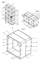
- Fig. 1 :
- ein aus acht übereinander und nebeneinander angeordneten Regalelementen bestehendes Regalsystem auf Fußteilen unter Verwendung der Verbindungselemente (3), (4) und (5);
- Fig. 2 :
- ein aus zwei nebeneinander angeordneten Regalteilen bestehendes Regal (Sidebord);
- Fig. 3:
- ein Einzel-Regalelement mit den Verbindungselementen (3) zur Verbindung der vier Grundelemente (1);
- Fig. 4 :
- in schematischer Darstellung das Regalelement gemäß Fig. 3 vor dem Einsatz der Verbindungselemente (3);
- Fig. 5 :
- als Detail aus Fig. 3 das obere Grundelement (1) mit in dieses eingesetzten Verbindungselementen (3);
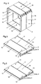
- Fig. 6:
- das Grundelement (1) aus Hohlprofil mit sechs parallel verlaufenden Kammern;
- Fig. 7:
- das Verbindungselement (3) (Eckverbinder);
- Fig. 8 :
- das Verbindungselement (4) (T-Verbinder);
- Fig. 9 :
- das Verbindungselement (5) (Kreuz-Verbinder);
- Fig. 10:
- das Verbindungselement (6) (I-Verbinder);
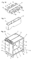
- Fig. 11:
- das Fußteil (12) für das Regalsystem;
- Fig. 12:
- ein Einzel-Regalelement als Bodenelement mit angesetzten Fußteilen (12) und eingesetzten Verbindungselementen (5) vor dem Ansetzen der Grundelemente (1) für das seitlich anschließende sowie das nach oben anschließende Regalelement;
- Fig. 13 :
- als Detail zwei aneinander grenzende Regalelemente von ihrer einen Außenseite her gesehen mit jeweils einem eingesetzten Verbindungselement (4) und einem darüber vertikal angeordneten Grundelement für das folgende Regalelement, vor dem Einsatz des Grundelements in die freien Arme der Verbindungselemente (4) und/oder formschlüssigen Verbindung der drei Regalelemente;
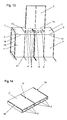
- Fig. 14 :
- ein Grundelement mit halber Länge des Grundelements (1);
- Fig. 15:
- das Regalsystem mit unterschiedlich großen bzw. hohen Regalelementen;
- Fig. 16:
- das Regalsystem mit gegeneinander versetzt vertikal und horizontal angeordneten Regalelementen.
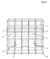
- Fig. 1:
- a shelving system consisting of eight shelf elements arranged one above the other and next to one another on foot parts using the connecting elements (3), (4) and (5);
- Fig. 2:
- a shelf consisting of two juxtaposed shelves (sidebord);
- 3:
- a single shelf element with the connecting elements (3) for connecting the four basic elements (1);
- 4:
- in a schematic representation of the shelf element of Figure 3 before the use of the connecting elements (3).
- Fig. 5:
- as a detail of Figure 3, the upper base element (1) with inserted therein connecting elements (3).
- Fig. 6:
- the basic element (1) of hollow profile with six parallel chambers;
- Fig. 7:
- the connecting element (3) (corner connector);
- Fig. 8:
- the connecting element (4) (T-connector);
- Fig. 9:
- the connecting element (5) (cross-connector);
- Fig. 10:
- the connecting element (6) (I-connector);
- Fig. 11:
- the foot part (12) for the shelving system;
- Fig. 12:
- a single shelf element as a floor element with attached foot parts (12) and inserted connecting elements (5) before applying the basic elements (1) for the laterally adjoining and the upwardly adjoining shelf element;
- Fig. 13:
- as a detail two adjacent shelf elements seen from their one outer side, each with an inserted connecting element (4) and a vertically arranged above basic element for the following shelf element, before the use of the basic element in the free arms of the connecting elements (4) and / or positive connection the three shelf elements;
- Fig. 14:
- a base member of half length of the base member (1);
- Fig. 15:
- the shelving system with different sized or high shelf elements;
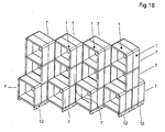
- Fig. 16:
- the shelving system with offset vertically and horizontally arranged shelf elements.
Das Regalsystem besteht aus einer Mehrzahl von kubusförmigen Regalelementen (7), die durch senkrechtes und/oder waagerechtes Aneinandersetzen von Grundelementen (1, 1') und ihre Verbindung mittels der Verbindungselemente (3, 4, 5, 6) gebildet werden, wobei das jeweils einzusetzende Verbindungselement durch die Anzahl der beim Regalaufbau jeweils zusammentreffenden Grundelemente (1, 1') bestimmt wird.The shelving system consists of a plurality of cube-shaped shelf elements (7), which are formed by vertical and / or horizontal engagement of basic elements (1, 1 ') and their connection by means of the connecting elements (3, 4, 5, 6), wherein each to be used connecting element by the number of the shelf assembly respectively coinciding basic elements (1, 1 ') is determined.
Die Grundelemente (1,1') sind Platten aus Hohlprofil mit mindestens einer Kammer, im dargestellten Ausführungsbeispiel mit sechs parallel nebeneinander liegenden Kammern (2). Die Grundelemente (1, 1') bilden quadratische oder rechteckige Flächen, ihre Abmessungen sind dabei frei bestimmbar. Die Verbindungselemente (3, 4, 5, 6) werden formschlüssig fest, jedoch lösbar in die Grundelemente (1, 1') eingesetzt.The basic elements (1,1 ') are plates of hollow profile with at least one chamber, in the illustrated embodiment with six parallel adjacent chambers (2). The basic elements (1, 1 ') form square or rectangular surfaces, their dimensions are freely determinable. The connecting elements (3, 4, 5, 6) are positively fixed, but releasably inserted into the basic elements (1, 1 ').
Zur Erstellung eines ersten Regalelements (7) als Basiselement werden, wie in Fig. 3 bis 5 dargestellt, vier Grundelemente (1) zu einem Kubus mittels Verbindungselementen (3, 4, 5) zusammengesetzt. Zum An-/Aufbau weiterer Regalelemente (7) daran werden dabei die Verbindungselemente (4) und/oder (5) eingesetzt. Soweit Regalelemente entweder nur aufeinandergesetzt, also das Regal vertikal aufgebaut, oder nur horizontal aneinandergesetzt werden, werden die jeweils aufeinanderstoßenden drei Grundelemente (1, 1') durch das T-förmige Verbindungselement (4) miteinander verbunden. Dabei greift jeweils einer der Arme (8, 9, 10) in die Kammer (2) der Grundelemente (1, 1') ein, so daß die drei Grundelemente bündig und fest, jedoch lösbar verbunden sind. Sollen Regale sowohl aus aufeinandergesetzten als auch aus aneinandergesetzten Regalelementen (7) gebildet werden, so werden die im Bereich des An- und Aufbaus aufeinanderstoßenden jeweils zwei vertikalen und zwei horizontalen Grundelemente (1) durch die kreuzförmigen Verbinbungselemente (5) miteinander verbunden, wobei jeweils einer der Arme (8, 9, 10, 11) in die ihm zugeordnete Kammer (2) des Grundelements (1) eingreift.To create a first shelf element (7) as a base element, as shown in FIGS. 3 to 5, four basic elements (1) are assembled into a cube by means of connecting elements (3, 4, 5). For attaching / constructing further shelf elements (7), the connecting elements (4) and / or (5) are used. As far as shelf elements either only juxtaposed, so the shelf is constructed vertically, or only horizontally juxtaposed, the respectively abutting three basic elements (1, 1 ') by the T-shaped connecting element (4) are interconnected. there engages in each case one of the arms (8, 9, 10) in the chamber (2) of the basic elements (1, 1 '), so that the three basic elements are flush and fixed, but releasably connected. If shelves are to be formed from stacked and stacked shelf elements (7), the two adjacent vertical and two horizontal base elements (1) in the region of the attachment and structure are interconnected by the cross-shaped connecting elements (5), one each the arms (8, 9, 10, 11) in its associated chamber (2) of the base element (1) engages.
Soweit nur ein einzelnes Regalelement (7) gebildet wird und dabei nur jeweils ein vertikal und ein horizontal angeordnetes Grundelement (1, 1') aufeinandertreffen und zu verbinden sind, erfolgt die Verbindung durch das Verbindungselement (3) mit den beiden im rechten Winkel zueinander angeordneten Armen (9, 10), die in der beschriebenen Weise in die zugeordneten Kammern (2) der beiden Grundelemente (1,1') eingesetzt werden und diese formschlüssig, jedoch lösbar verbinden. In der dargestellten Ausführungsform ist das Verbindungelement (3) auf seiner den Armen (9, 10) gegenüberliegenden Außenseite abgerundet; diese Außenseite kann jedoch auch andere Formen, z. B. rechteckigen, quadratischen, dreieckigen Querschnitt haben.As far as only a single shelf element (7) is formed and only one vertically and one horizontally arranged base element (1, 1 ') meet and are to connect, the connection is made by the connecting element (3) with the two at right angles to each other Arms (9, 10) which are used in the manner described in the associated chambers (2) of the two basic elements (1,1 ') and connect them positively, but releasably. In the illustrated embodiment, the connecting element (3) on its the arms (9, 10) opposite the outside is rounded; However, this outside can also other forms, eg. B. have rectangular, square, triangular cross-section.
Soweit beim Aufbau des Regals durch vertikales oder horizontales Aneinandersetzen von zwei Grundelementen (1, 1') ohne zusätzliche Grundelemente ein größeres Regalelement (7, 7') gebildet werden soll, wie in Fig. 15 dargestellt, werden die beiden Grundelemente (1, 1') mittels des Verbindungselements (6) formschlüssig, jedoch lösbar miteinander verbunden, wobei das Verbindungselement (6) nur die beiden in einer Ebene gegenüberliegende Arme (8) und (9) hat, die jeweils in die zusammenzusetzenden Grundelemente (1, 1') eingesetzt werden.As far as a larger shelf element (7, 7 ') is to be formed in the construction of the shelf by vertical or horizontal engagement of two basic elements (1, 1') without additional basic elements, as shown in Fig. 15, the two basic elements (1, 1 ') by means of the connecting element (6) positively, but releasably connected to each other, wherein the connecting element (6) only the two in a plane opposite arms (8) and (9), each in the zusammenzusetzenden basic elements (1, 1') be used.
In bevorzugter Ausführungsform sind, wie in den Zeichnungen, insbesondere in Fig. 7 bis 10, dargestellt, jeweils drei Verbindungselemente (3, 4, 5, 6) kongruent nebeneinander angeordnet und miteinander starr als einheitliches Bauteil verbunden, wobei der Abstand zwischen zwei aneinandergrenzenden Verbindungselementen bzw. ihrer Arme (8, 9; 9, 10; 8, 9, 10; 8, 9, 10, 11) so bemessen ist, daß das Bauteil mit den jeweiligen Armen der Verbindungselemente in drei Kammern (2) der zu verbindenden Grundelemente (1, 1') eingesetzt werden kann. Dadurch erhält die Verbindung mehrerer Grundelemente (1,1') erhöhte Stabilität. Es liegt jedoch im Rahmen der Erfindung, wenn jeweils Einzel-Verbindungselemente (3, 4, 5, 6) oder Bauteile aus zwei, vier oder mehreren Verbindungselementen entsprechend der Anzahl der Kammern (2) der Grundelemente (1, 1 ') verwandt werden. Die bevorzugte Ausführungsform von Bauteilen aus jeweils drei miteinander fest verbundenen Verbindungselementen (3, 4, 5, 6) ermöglicht es, sie wahlweise in den drei vorderen oder in den drei hinteren, aber auch in drei nebeneinander liegenden Kammern (2) eines Grundelements einzusetzen. Dadurch wird es insbesondere möglich, auf ein Regalelement (7) ein weiteres aufzusetzen und/oder anzusetzen, das gegenüber dem erstgenannten Regalelement (7) zurückspringt oder vorspringt. Ebenso können bei dieser bevorzugten Ausführungsform, wie aus Fig. 13 ersichtlich, zwei hintereinandergestellte Regalelemente (7) derart miteinander verbunden werden, daß jeweils ein Bauelement aus drei Verbindungselementen (4) in die drei hinteren Kammern (2) des oberen Grundelements des vorderen Regalelements (7) einerseits und in die drei vorderen Kammern (2) des oberen Grundelements des hinteren Regalelements (7) eingesetzt werden und das vertikale Grundelement (1) eines weiteren, auf die beiden Regalelemente aufzusetzenden Regalelements (7) mit diesen durch die Arme (8) der Verbindungselemente (4), diese übergreifend, zusammengesetzt ist.In a preferred embodiment, as shown in the drawings, in particular in Fig. 7 to 10, each three connecting elements (3, 4, 5, 6) arranged congruent side by side and rigidly connected together as a single component, wherein the distance between two adjacent connecting elements or their arms (8, 9, 9, 10, 8, 9, 10, 8, 9, 10, 11) is dimensioned so that the component with the respective arms of the connecting elements in three chambers (2) of the basic elements to be connected (1, 1 ') can be used. This gives the compound of several basic elements (1,1 ') increased stability. However, it is within the scope of the invention, if in each case individual connecting elements (3, 4, 5, 6) or components of two, four or more connecting elements corresponding to the number of chambers (2) of the basic elements (1, 1 ') are used. The preferred embodiment of components each consisting of three mutually firmly connected connecting elements (3, 4, 5, 6) makes it possible to use them either in the three front or in the three rear, but also in three adjacent chambers (2) of a basic element. This makes it possible, in particular, to set up and / or set up a shelf element (7) which rebounds or protrudes in relation to the first-mentioned shelf element (7). Likewise, in this preferred embodiment, as shown in FIG. 13, two successive shelf elements (7) are interconnected such that in each case a component of three connecting elements (4) in the three rear chambers (2) of the upper base element of the front shelf element ( 7) on the one hand and in the three front chambers (2) of the upper base element of the rear shelf element (7) are used and the vertical base element (1) of a further, to be placed on the two shelf elements shelf element (7) with these by the arms (8) the connecting elements (4), this cross-over, is composed.
Zur Bildung kleinerer, also niedrigerer oder schmalerer Regalelemente (7") sind erfindungsgemäß Grundelemente (1') mit geringerer Frontlänge als bei den Grundelementen (1) vorgesehen, beispielsweise mit halber Frontlänge, die im übrigen wie diese Grundelemente (1) gestaltet sind.In order to form smaller, ie lower or narrower shelf elements (7 "), basic elements (1 ') are provided according to the invention with a shorter front length than in the basic elements (1), for example with half the front length, which otherwise are designed like these basic elements (1).
Als zusätzliches Bauteil ist, wie aus Fig.11 ersichtlich, ein Fußteil (12) für den Fall vorgesehen, daß der Benutzer des Regals dieses nicht mit den Regalelementen (7) unmittelbar auf den Fußboden aufsetzen will. Dieses Fußteil (12) ist ebenfalls ein Hohlprofil mit mindestens einer Kammer und entspricht in seiner Ausgestaltung im wesentlichen dem Grundelement (1, 1'). Es hat insbesondere wie dieses den Armen (8, 9, 10, 11) der Verbindungselemente (4, 5) angepaßte Kammern (2'). Sollen am erfindungsgemäßen Regal solche Fußteile (12) angebracht werden, sind an den unteren Regalelementen (7) im Bereich der Verbindung der Grundelemente (1, 1') an den seitlichen Enden des Regals die Verbindungselemente (4) bzw. die Verbindungselemente (5) im Bereich aneinander anschließender Regalelemente (7) angeordnet, die mit ihren freien, nach unten ragenden Armen (9) in die Fußteile (12) formschlüssig eingreifen.As an additional component, as shown in Fig.11, a foot part (12) provided for the case that the user of the shelf does not want to put this with the shelf elements (7) directly on the floor. This foot part (12) is also a hollow profile with at least one chamber and corresponds in its embodiment substantially the basic element (1, 1 '). It has in particular like this the arms (8, 9, 10, 11) of the connecting elements (4, 5) adapted chambers (2 '). If such foot parts (12) are to be mounted on the shelf according to the invention, the connecting elements (4) or the connecting elements ( 5) are connected to the lower shelf elements (7) in the area of the connection of the basic elements (1, 1 ') ) in the region of adjoining shelf elements (7), which engage positively with their free, downwardly projecting arms (9) in the foot parts (12).
Ohne daß es erfindungswesentlich ist, können die Verbindungselemente (3, 4, 5, 6) in ihren Armen (8, 9, 10, 11) Bohrungen (13) und die Grundelemente (1, 1') im Bereich des Eingriffs der Arme der Verbindungselemente Bohrungen (14) haben, die nach dem Einsetzen des jeweiligen Verbindungselements in das Grundelement kongruent angeordnet sind und in die Sicherungsstifte (15) zur zusätzlichen Sicherung der Verbindung eingesetzt werden.Without it being essential to the invention, the connecting elements (3, 4, 5, 6) in their arms (8, 9, 10, 11) bores (13) and the basic elements (1, 1 ') in the region of engagement of the arms Connecting elements have holes (14) which are arranged congruent after insertion of the respective connecting element in the base element and in the locking pins (15) are used for additional securing of the connection.
Als vorteilhafte Weiterbildung des erfindungsgemäßen Regalsystems können in den Grundelementen (1,1') auf ihrer Ober- und Unterseite im Bereich ihrer Vorderkante und/oder ihrer Hinterkante und/oder an frei wählbaren Stellen der Ober- und Unterseite, vorzugsweise auf mittlerer Breite, Längsnuten (16, 17) angebracht sein. In diese Längsnuten (16, 17) können beim Zusammenbau des Regalelements (7), aber auch im zusammengebauten Zustand, in ihren Maßen angepaßte Platten (18) als Rückwand oder Trennwand für das jeweilige Regalelement (7) eingesetzt werden.As an advantageous development of the shelf system according to the invention can in the basic elements (1,1 ') on its top and bottom in the region of its front edge and / or its rear edge and / or at arbitrary positions of the top and bottom, preferably on average width, longitudinal grooves (16, 17). In these longitudinal grooves (16, 17) can during assembly the shelf element (7), but also in the assembled state, in their dimensions adapted plates (18) are used as a rear wall or partition for the respective shelf element (7).
Natürlich liegt es im Rahmen der Erfindung, wenn aus den beschriebenen Bauteilen nur ein einzelnes Regalelement (7) mit den Verbindungselementen (3) als Einzelkubus gebildet wird oder zwei oder mehrere seitlich aneinandergrenzende Regalelemente unter Verwendung von Verbindungselementen (3) und (4) nach Art von Sidebords zusammengesetzt werden.Of course, it is within the scope of the invention, if from the described components only a single shelf element (7) with the connecting elements (3) is formed as a single cube or two or more laterally adjacent shelf elements using connecting elements (3) and (4) according to Art composed of sidebords.
Das Regalsystem und seine beschriebenen Bauteile, insbesondere die Grundelemente (1, 1'), die Verbindungselemente (3 bis 6), die Fußteile (12) und/oder Platten (18) werden vorzugsweise aus starrem, jedoch bruchsicherem Kunststoff, aus Leichtmetallprofil bzw. -gußteilen oder auch aus anderem Material hergestellt.The shelving system and its components described, in particular the basic elements (1, 1 '), the connecting elements (3 to 6), the foot parts (12) and / or plates (18) are preferably made of rigid, but shatterproof plastic, light metal profile or castings or also made of other material.
Durch die Erfindung wird ein Regalsystem geschaffen, bei dem nahezu unbegrenzte Variationen durch den An- und/oder Aufbau einer willkürlich wählbaren Mehrzahl von Regalelementen (7), je nach den Einsatzzwecken und/oder den Gestaltungswünschen des Verwenders möglich sind. Dabei können einzelne Regalelemente (7) gegenüber den anderen innerhalb eines zusammengesetzten Regals auch vorspringen oder zurückspringen. Diese Variationsmöglichkeit übersteigt bereits an sich die bekannter Regalsysteme. Vor allem wird der Auf- und Abbau von Regalen sowie die Änderung vorhandener Variationen und/oder deren Erweiterung durch die Erfindung wesentlich vereinfacht. Für die Montage und Demontage von Regalen nach dem erfindungsgemäßen System und seiner einzelnen Bestandteile wird kein Werkzeug benötigt; sämtliche Einzelteile können von Hand zusammengesetzt und wieder gelöst werden. Dabei verkürzt sich dementsprechend der Zeitaufwand für Montage und Demontage. Hinzu kommt als Vorteil, daß das System nur wenige Bauelemente umfaßt, insbesondere die Grundelemente gleichermaßen als Seiten- und Zwischenwände sowie als Boden und Decken der Regalelemente innerhalb eines Regals dienen. Auch die Verbindungselemente (2 bis 6) weisen die gleiche Grundform und übereinstimmende Gestaltung ihrer Arme auf. Damit reduzieren sich zugleich die Herstellungskosten und der Verbraucherpreis. Besonders vorteilhaft ist das neue Regalsystem durch die einfache und schnelle Montage und Demontage sowie Veränderbarkeit für die Präsentation von Waren, z. B. an unterschiedlichen Einsatzorten.The invention provides a shelving system in which virtually unlimited variations are possible by the attachment and / or construction of a randomly selectable plurality of shelf elements (7), depending on the intended use and / or the design wishes of the user. In this case, individual shelf elements (7) can also project or spring back relative to the others within a composite shelf. This possibility of variation already exceeds the known shelving systems. Above all, the construction and dismantling of shelves as well as the modification of existing variations and / or their extension is substantially simplified by the invention. For the assembly and disassembly of shelves according to the system according to the invention and its individual components no tool is needed; All items can be assembled by hand and released again. This shortens the time required for assembly and disassembly accordingly. An additional advantage is that the system only a few components includes, in particular serve the basic elements equally as side and intermediate walls as well as the floor and ceilings of the shelf elements within a shelf. The connecting elements (2 to 6) have the same basic shape and matching design of their arms. This reduces both the cost of production and the consumer price. Particularly advantageous is the new shelving system by the simple and quick assembly and disassembly and variability for the presentation of goods, such. B. at different locations.
Claims (11)
Applications Claiming Priority (1)
| Application Number | Priority Date | Filing Date | Title |
|---|---|---|---|
| DE200620003227 DE202006003227U1 (en) | 2005-08-26 | 2006-02-26 | Rack system for use in e.g. living area, has rack units with individual construction units that are assembled and disassembled by connection units, where arrangement and combination of rack units are freely selectable and changeable |
Publications (2)
| Publication Number | Publication Date |
|---|---|
| EP1834545A2 true EP1834545A2 (en) | 2007-09-19 |
| EP1834545A3 EP1834545A3 (en) | 2009-05-27 |
Family
ID=37308909
Family Applications (1)
| Application Number | Title | Priority Date | Filing Date |
|---|---|---|---|
| EP07003373A Withdrawn EP1834545A3 (en) | 2006-02-26 | 2007-02-17 | Shelving system |
Country Status (2)
| Country | Link |
|---|---|
| EP (1) | EP1834545A3 (en) |
| DE (1) | DE202006003227U1 (en) |
Families Citing this family (3)
| Publication number | Priority date | Publication date | Assignee | Title |
|---|---|---|---|---|
| DE102008019739A1 (en) | 2008-04-19 | 2009-10-22 | Lothar Welz | Shelf consists of perpendicular and horizontal plates, which form shelf panel by connecting front sides in corner connection, T-connection and cross connection |
| DE102008045645B4 (en) * | 2008-09-03 | 2015-05-07 | Wolf Deiß | Furniture plug system with a variety of individual furniture modules |
| ITUD20110099A1 (en) * | 2011-06-24 | 2012-12-25 | P One S R L | FURNISHING ELEMENT AS A LIBRARY, SHELF, SHELVING, OR SIMILAR |
Citations (5)
| Publication number | Priority date | Publication date | Assignee | Title |
|---|---|---|---|---|
| GB1167982A (en) * | 1967-02-28 | 1969-10-22 | Donald Maxwell | Improvements in or relating to Furniture Construction |
| FR2093669A5 (en) * | 1970-05-29 | 1972-01-28 | Anic Spa | |
| DE2056158A1 (en) * | 1970-11-14 | 1972-05-18 | Dynamit Nobel Ag, 5210 Troisdorf | Piece of furniture with at least the middle and side walls, ceilings and floors made of plastic |
| DE2059870A1 (en) * | 1970-12-04 | 1972-06-29 | Franz Schoerghuber | Dismountable furniture, e.g. Shelf, box, cupboard or the like. |
| DE10336364A1 (en) * | 2003-08-06 | 2005-03-10 | Dominik Lutz | Piece of furniture or shelves for use in house or office is made of square modular panels with grooved edges accommodating T-section capping strips and fastened together to make box shelf modules |
-
2006
- 2006-02-26 DE DE200620003227 patent/DE202006003227U1/en not_active Expired - Lifetime
-
2007
- 2007-02-17 EP EP07003373A patent/EP1834545A3/en not_active Withdrawn
Patent Citations (5)
| Publication number | Priority date | Publication date | Assignee | Title |
|---|---|---|---|---|
| GB1167982A (en) * | 1967-02-28 | 1969-10-22 | Donald Maxwell | Improvements in or relating to Furniture Construction |
| FR2093669A5 (en) * | 1970-05-29 | 1972-01-28 | Anic Spa | |
| DE2056158A1 (en) * | 1970-11-14 | 1972-05-18 | Dynamit Nobel Ag, 5210 Troisdorf | Piece of furniture with at least the middle and side walls, ceilings and floors made of plastic |
| DE2059870A1 (en) * | 1970-12-04 | 1972-06-29 | Franz Schoerghuber | Dismountable furniture, e.g. Shelf, box, cupboard or the like. |
| DE10336364A1 (en) * | 2003-08-06 | 2005-03-10 | Dominik Lutz | Piece of furniture or shelves for use in house or office is made of square modular panels with grooved edges accommodating T-section capping strips and fastened together to make box shelf modules |
Also Published As
| Publication number | Publication date |
|---|---|
| DE202006003227U1 (en) | 2006-10-12 |
| EP1834545A3 (en) | 2009-05-27 |
Similar Documents
| Publication | Publication Date | Title |
|---|---|---|
| EP0813376B1 (en) | Kit for a shelf unit | |
| DE2733283A1 (en) | Extruded profile for modular frame - has rounded edges with steps to seat facing panels and apertures to locate coupling plates | |
| DE102008005067A1 (en) | Cylindrical wall panel for furniture- and rack system in private home, has four side surfaces, where two of side surfaces have recesses running parallel to edges and extending up to base surface | |
| DE2440290A1 (en) | IMPROVEMENTS TO SHELVES AND STORAGE RACKS AND MEANS FOR THEIR VARIOUS DESIGN | |
| EP1834545A2 (en) | Shelving system | |
| EP1776895A1 (en) | Furniture with structural frame | |
| DE102005008644A1 (en) | Shelving system, comprising basic box and square panels to be added in order to form bottom, side, or top of more boxes | |
| DE2823772A1 (en) | CONSTRUCTION ELEMENT FOR THREE-DIMENSIONAL OBJECTS, E.G. FURNITURE | |
| EP2904942A2 (en) | Shelf and/or display cabinet | |
| DE4001089C2 (en) | Component set | |
| EP4104713A1 (en) | Arrangement for forming a modular furniture system | |
| DE7516704U (en) | Frame, in particular for advertising and sales | |
| DE202016000831U1 (en) | Modular furniture system | |
| DE102020003941A1 (en) | Connection device and a panel system based on this | |
| DE102004033876A1 (en) | Three-dimensional structure system | |
| EP1201160A1 (en) | Modular furniture system | |
| DE2840729C2 (en) | Easily dismantled and assembled frame or shelf | |
| DE19800824C2 (en) | shelf kit | |
| DE3411348A1 (en) | Furniture element | |
| AT508987B1 (en) | SHELF WITH ONE FLOOR PART AND AT LEAST ONE SIDE PART | |
| DE3441315A1 (en) | Set of structural elements for producing connected panel structures | |
| EP2570049B1 (en) | Shelf | |
| DE102021109616A1 (en) | Variable furniture element and modular furniture system made up of several furniture elements | |
| WO1994027053A1 (en) | Furniture assembly system with knot binding rods | |
| DE3737112A1 (en) | System of element groups which can be assembled and comprises basic elements |
Legal Events
| Date | Code | Title | Description |
|---|---|---|---|
| PUAI | Public reference made under article 153(3) epc to a published international application that has entered the european phase |
Free format text: ORIGINAL CODE: 0009012 |
|
| AK | Designated contracting states |
Kind code of ref document: A2 Designated state(s): AT BE BG CH CY CZ DE DK EE ES FI FR GB GR HU IE IS IT LI LT LU LV MC NL PL PT RO SE SI SK TR |
|
| AX | Request for extension of the european patent |
Extension state: AL BA HR MK YU |
|
| PUAL | Search report despatched |
Free format text: ORIGINAL CODE: 0009013 |
|
| AK | Designated contracting states |
Kind code of ref document: A3 Designated state(s): AT BE BG CH CY CZ DE DK EE ES FI FR GB GR HU IE IS IT LI LT LU LV MC NL PL PT RO SE SI SK TR |
|
| AX | Request for extension of the european patent |
Extension state: AL BA HR MK RS |
|
| RIC1 | Information provided on ipc code assigned before grant |
Ipc: F16B 12/46 20060101ALN20070629BHEP Ipc: A47B 47/00 20060101AFI20090421BHEP |
|
| 17P | Request for examination filed |
Effective date: 20091124 |
|
| AKX | Designation fees paid |
Designated state(s): AT BE BG CH CY CZ DE DK EE ES FI FR GB GR HU IE IS IT LI LT LU LV MC NL PL PT RO SE SI SK TR |
|
| 17Q | First examination report despatched |
Effective date: 20100118 |
|
| STAA | Information on the status of an ep patent application or granted ep patent |
Free format text: STATUS: THE APPLICATION IS DEEMED TO BE WITHDRAWN |
|
| 18D | Application deemed to be withdrawn |
Effective date: 20120901 |