EP1833665B1 - Plastic panel - Google Patents
Plastic panel Download PDFInfo
- Publication number
- EP1833665B1 EP1833665B1 EP06701956A EP06701956A EP1833665B1 EP 1833665 B1 EP1833665 B1 EP 1833665B1 EP 06701956 A EP06701956 A EP 06701956A EP 06701956 A EP06701956 A EP 06701956A EP 1833665 B1 EP1833665 B1 EP 1833665B1
- Authority
- EP
- European Patent Office
- Prior art keywords
- bonding
- panel
- adhesive
- plastic panel
- grooves
- Prior art date
- Legal status (The legal status is an assumption and is not a legal conclusion. Google has not performed a legal analysis and makes no representation as to the accuracy of the status listed.)
- Expired - Lifetime
Links
Images


Classifications
-
- B—PERFORMING OPERATIONS; TRANSPORTING
- B29—WORKING OF PLASTICS; WORKING OF SUBSTANCES IN A PLASTIC STATE IN GENERAL
- B29C—SHAPING OR JOINING OF PLASTICS; SHAPING OF MATERIAL IN A PLASTIC STATE, NOT OTHERWISE PROVIDED FOR; AFTER-TREATMENT OF THE SHAPED PRODUCTS, e.g. REPAIRING
- B29C65/00—Joining or sealing of preformed parts, e.g. welding of plastics materials; Apparatus therefor
- B29C65/48—Joining or sealing of preformed parts, e.g. welding of plastics materials; Apparatus therefor using adhesives, i.e. using supplementary joining material; solvent bonding
-
- B—PERFORMING OPERATIONS; TRANSPORTING
- B32—LAYERED PRODUCTS
- B32B—LAYERED PRODUCTS, i.e. PRODUCTS BUILT-UP OF STRATA OF FLAT OR NON-FLAT, e.g. CELLULAR OR HONEYCOMB, FORM
- B32B3/00—Layered products comprising a layer with external or internal discontinuities or unevennesses, or a layer of non-planar shape; Layered products comprising a layer having particular features of form
- B32B3/02—Layered products comprising a layer with external or internal discontinuities or unevennesses, or a layer of non-planar shape; Layered products comprising a layer having particular features of form characterised by features of form at particular places, e.g. in edge regions
- B32B3/06—Layered products comprising a layer with external or internal discontinuities or unevennesses, or a layer of non-planar shape; Layered products comprising a layer having particular features of form characterised by features of form at particular places, e.g. in edge regions for securing layers together; for attaching the product to another member, e.g. to a support, or to another product, e.g. groove/tongue, interlocking
-
- B—PERFORMING OPERATIONS; TRANSPORTING
- B29—WORKING OF PLASTICS; WORKING OF SUBSTANCES IN A PLASTIC STATE IN GENERAL
- B29C—SHAPING OR JOINING OF PLASTICS; SHAPING OF MATERIAL IN A PLASTIC STATE, NOT OTHERWISE PROVIDED FOR; AFTER-TREATMENT OF THE SHAPED PRODUCTS, e.g. REPAIRING
- B29C66/00—General aspects of processes or apparatus for joining preformed parts
- B29C66/01—General aspects dealing with the joint area or with the area to be joined
- B29C66/05—Particular design of joint configurations
- B29C66/10—Particular design of joint configurations particular design of the joint cross-sections
- B29C66/11—Joint cross-sections comprising a single joint-segment, i.e. one of the parts to be joined comprising a single joint-segment in the joint cross-section
- B29C66/112—Single lapped joints
-
- B—PERFORMING OPERATIONS; TRANSPORTING
- B29—WORKING OF PLASTICS; WORKING OF SUBSTANCES IN A PLASTIC STATE IN GENERAL
- B29C—SHAPING OR JOINING OF PLASTICS; SHAPING OF MATERIAL IN A PLASTIC STATE, NOT OTHERWISE PROVIDED FOR; AFTER-TREATMENT OF THE SHAPED PRODUCTS, e.g. REPAIRING
- B29C66/00—General aspects of processes or apparatus for joining preformed parts
- B29C66/01—General aspects dealing with the joint area or with the area to be joined
- B29C66/05—Particular design of joint configurations
- B29C66/10—Particular design of joint configurations particular design of the joint cross-sections
- B29C66/11—Joint cross-sections comprising a single joint-segment, i.e. one of the parts to be joined comprising a single joint-segment in the joint cross-section
- B29C66/112—Single lapped joints
- B29C66/1122—Single lap to lap joints, i.e. overlap joints
-
- B—PERFORMING OPERATIONS; TRANSPORTING
- B29—WORKING OF PLASTICS; WORKING OF SUBSTANCES IN A PLASTIC STATE IN GENERAL
- B29C—SHAPING OR JOINING OF PLASTICS; SHAPING OF MATERIAL IN A PLASTIC STATE, NOT OTHERWISE PROVIDED FOR; AFTER-TREATMENT OF THE SHAPED PRODUCTS, e.g. REPAIRING
- B29C66/00—General aspects of processes or apparatus for joining preformed parts
- B29C66/01—General aspects dealing with the joint area or with the area to be joined
- B29C66/05—Particular design of joint configurations
- B29C66/10—Particular design of joint configurations particular design of the joint cross-sections
- B29C66/11—Joint cross-sections comprising a single joint-segment, i.e. one of the parts to be joined comprising a single joint-segment in the joint cross-section
- B29C66/114—Single butt joints
-
- B—PERFORMING OPERATIONS; TRANSPORTING
- B29—WORKING OF PLASTICS; WORKING OF SUBSTANCES IN A PLASTIC STATE IN GENERAL
- B29C—SHAPING OR JOINING OF PLASTICS; SHAPING OF MATERIAL IN A PLASTIC STATE, NOT OTHERWISE PROVIDED FOR; AFTER-TREATMENT OF THE SHAPED PRODUCTS, e.g. REPAIRING
- B29C66/00—General aspects of processes or apparatus for joining preformed parts
- B29C66/01—General aspects dealing with the joint area or with the area to be joined
- B29C66/05—Particular design of joint configurations
- B29C66/10—Particular design of joint configurations particular design of the joint cross-sections
- B29C66/12—Joint cross-sections combining only two joint-segments; Tongue and groove joints; Tenon and mortise joints; Stepped joint cross-sections
- B29C66/128—Stepped joint cross-sections
- B29C66/1282—Stepped joint cross-sections comprising at least one overlap joint-segment
- B29C66/12821—Stepped joint cross-sections comprising at least one overlap joint-segment comprising at least two overlap joint-segments
-
- B—PERFORMING OPERATIONS; TRANSPORTING
- B29—WORKING OF PLASTICS; WORKING OF SUBSTANCES IN A PLASTIC STATE IN GENERAL
- B29C—SHAPING OR JOINING OF PLASTICS; SHAPING OF MATERIAL IN A PLASTIC STATE, NOT OTHERWISE PROVIDED FOR; AFTER-TREATMENT OF THE SHAPED PRODUCTS, e.g. REPAIRING
- B29C66/00—General aspects of processes or apparatus for joining preformed parts
- B29C66/01—General aspects dealing with the joint area or with the area to be joined
- B29C66/05—Particular design of joint configurations
- B29C66/10—Particular design of joint configurations particular design of the joint cross-sections
- B29C66/12—Joint cross-sections combining only two joint-segments; Tongue and groove joints; Tenon and mortise joints; Stepped joint cross-sections
- B29C66/128—Stepped joint cross-sections
- B29C66/1282—Stepped joint cross-sections comprising at least one overlap joint-segment
- B29C66/12821—Stepped joint cross-sections comprising at least one overlap joint-segment comprising at least two overlap joint-segments
- B29C66/12822—Stepped joint cross-sections comprising at least one overlap joint-segment comprising at least two overlap joint-segments comprising at least three overlap joint-segments
-
- B—PERFORMING OPERATIONS; TRANSPORTING
- B29—WORKING OF PLASTICS; WORKING OF SUBSTANCES IN A PLASTIC STATE IN GENERAL
- B29C—SHAPING OR JOINING OF PLASTICS; SHAPING OF MATERIAL IN A PLASTIC STATE, NOT OTHERWISE PROVIDED FOR; AFTER-TREATMENT OF THE SHAPED PRODUCTS, e.g. REPAIRING
- B29C66/00—General aspects of processes or apparatus for joining preformed parts
- B29C66/01—General aspects dealing with the joint area or with the area to be joined
- B29C66/05—Particular design of joint configurations
- B29C66/10—Particular design of joint configurations particular design of the joint cross-sections
- B29C66/12—Joint cross-sections combining only two joint-segments; Tongue and groove joints; Tenon and mortise joints; Stepped joint cross-sections
- B29C66/128—Stepped joint cross-sections
- B29C66/1284—Stepped joint cross-sections comprising at least one butt joint-segment
-
- B—PERFORMING OPERATIONS; TRANSPORTING
- B29—WORKING OF PLASTICS; WORKING OF SUBSTANCES IN A PLASTIC STATE IN GENERAL
- B29C—SHAPING OR JOINING OF PLASTICS; SHAPING OF MATERIAL IN A PLASTIC STATE, NOT OTHERWISE PROVIDED FOR; AFTER-TREATMENT OF THE SHAPED PRODUCTS, e.g. REPAIRING
- B29C66/00—General aspects of processes or apparatus for joining preformed parts
- B29C66/01—General aspects dealing with the joint area or with the area to be joined
- B29C66/05—Particular design of joint configurations
- B29C66/10—Particular design of joint configurations particular design of the joint cross-sections
- B29C66/12—Joint cross-sections combining only two joint-segments; Tongue and groove joints; Tenon and mortise joints; Stepped joint cross-sections
- B29C66/128—Stepped joint cross-sections
- B29C66/1286—Stepped joint cross-sections comprising at least one bevelled joint-segment
-
- B—PERFORMING OPERATIONS; TRANSPORTING
- B29—WORKING OF PLASTICS; WORKING OF SUBSTANCES IN A PLASTIC STATE IN GENERAL
- B29C—SHAPING OR JOINING OF PLASTICS; SHAPING OF MATERIAL IN A PLASTIC STATE, NOT OTHERWISE PROVIDED FOR; AFTER-TREATMENT OF THE SHAPED PRODUCTS, e.g. REPAIRING
- B29C66/00—General aspects of processes or apparatus for joining preformed parts
- B29C66/01—General aspects dealing with the joint area or with the area to be joined
- B29C66/32—Measures for keeping the burr form under control; Avoiding burr formation; Shaping the burr
- B29C66/322—Providing cavities in the joined article to collect the burr
-
- B—PERFORMING OPERATIONS; TRANSPORTING
- B29—WORKING OF PLASTICS; WORKING OF SUBSTANCES IN A PLASTIC STATE IN GENERAL
- B29C—SHAPING OR JOINING OF PLASTICS; SHAPING OF MATERIAL IN A PLASTIC STATE, NOT OTHERWISE PROVIDED FOR; AFTER-TREATMENT OF THE SHAPED PRODUCTS, e.g. REPAIRING
- B29C66/00—General aspects of processes or apparatus for joining preformed parts
- B29C66/50—General aspects of joining tubular articles; General aspects of joining long products, i.e. bars or profiled elements; General aspects of joining single elements to tubular articles, hollow articles or bars; General aspects of joining several hollow-preforms to form hollow or tubular articles
- B29C66/51—Joining tubular articles, profiled elements or bars; Joining single elements to tubular articles, hollow articles or bars; Joining several hollow-preforms to form hollow or tubular articles
- B29C66/54—Joining several hollow-preforms, e.g. half-shells, to form hollow articles, e.g. for making balls, containers; Joining several hollow-preforms, e.g. half-cylinders, to form tubular articles
-
- B—PERFORMING OPERATIONS; TRANSPORTING
- B32—LAYERED PRODUCTS
- B32B—LAYERED PRODUCTS, i.e. PRODUCTS BUILT-UP OF STRATA OF FLAT OR NON-FLAT, e.g. CELLULAR OR HONEYCOMB, FORM
- B32B3/00—Layered products comprising a layer with external or internal discontinuities or unevennesses, or a layer of non-planar shape; Layered products comprising a layer having particular features of form
- B32B3/26—Layered products comprising a layer with external or internal discontinuities or unevennesses, or a layer of non-planar shape; Layered products comprising a layer having particular features of form characterised by a particular shape of the outline of the cross-section of a continuous layer; characterised by a layer with cavities or internal voids ; characterised by an apertured layer
-
- B—PERFORMING OPERATIONS; TRANSPORTING
- B62—LAND VEHICLES FOR TRAVELLING OTHERWISE THAN ON RAILS
- B62D—MOTOR VEHICLES; TRAILERS
- B62D27/00—Connections between superstructure or understructure sub-units
- B62D27/02—Connections between superstructure or understructure sub-units rigid
- B62D27/026—Connections by glue bonding
-
- B—PERFORMING OPERATIONS; TRANSPORTING
- B62—LAND VEHICLES FOR TRAVELLING OTHERWISE THAN ON RAILS
- B62D—MOTOR VEHICLES; TRAILERS
- B62D29/00—Superstructures, understructures, or sub-units thereof, characterised by the material thereof
- B62D29/04—Superstructures, understructures, or sub-units thereof, characterised by the material thereof predominantly of synthetic material
-
- E—FIXED CONSTRUCTIONS
- E04—BUILDING
- E04C—STRUCTURAL ELEMENTS; BUILDING MATERIALS
- E04C2/00—Building elements of relatively thin form for the construction of parts of buildings, e.g. sheet materials, slabs, or panels
- E04C2/02—Building elements of relatively thin form for the construction of parts of buildings, e.g. sheet materials, slabs, or panels characterised by specified materials
- E04C2/10—Building elements of relatively thin form for the construction of parts of buildings, e.g. sheet materials, slabs, or panels characterised by specified materials of wood, fibres, chips, vegetable stems, or the like; of plastics; of foamed products
- E04C2/20—Building elements of relatively thin form for the construction of parts of buildings, e.g. sheet materials, slabs, or panels characterised by specified materials of wood, fibres, chips, vegetable stems, or the like; of plastics; of foamed products of plastics
-
- B—PERFORMING OPERATIONS; TRANSPORTING
- B29—WORKING OF PLASTICS; WORKING OF SUBSTANCES IN A PLASTIC STATE IN GENERAL
- B29C—SHAPING OR JOINING OF PLASTICS; SHAPING OF MATERIAL IN A PLASTIC STATE, NOT OTHERWISE PROVIDED FOR; AFTER-TREATMENT OF THE SHAPED PRODUCTS, e.g. REPAIRING
- B29C65/00—Joining or sealing of preformed parts, e.g. welding of plastics materials; Apparatus therefor
- B29C65/78—Means for handling the parts to be joined, e.g. for making containers or hollow articles, e.g. means for handling sheets, plates, web-like materials, tubular articles, hollow articles or elements to be joined therewith; Means for discharging the joined articles from the joining apparatus
- B29C65/7802—Positioning the parts to be joined, e.g. aligning, indexing or centring
- B29C65/7805—Positioning the parts to be joined, e.g. aligning, indexing or centring the parts to be joined comprising positioning features
- B29C65/7814—Positioning the parts to be joined, e.g. aligning, indexing or centring the parts to be joined comprising positioning features in the form of inter-cooperating positioning features, e.g. tenons and mortises
-
- B—PERFORMING OPERATIONS; TRANSPORTING
- B29—WORKING OF PLASTICS; WORKING OF SUBSTANCES IN A PLASTIC STATE IN GENERAL
- B29C—SHAPING OR JOINING OF PLASTICS; SHAPING OF MATERIAL IN A PLASTIC STATE, NOT OTHERWISE PROVIDED FOR; AFTER-TREATMENT OF THE SHAPED PRODUCTS, e.g. REPAIRING
- B29C65/00—Joining or sealing of preformed parts, e.g. welding of plastics materials; Apparatus therefor
- B29C65/78—Means for handling the parts to be joined, e.g. for making containers or hollow articles, e.g. means for handling sheets, plates, web-like materials, tubular articles, hollow articles or elements to be joined therewith; Means for discharging the joined articles from the joining apparatus
- B29C65/7802—Positioning the parts to be joined, e.g. aligning, indexing or centring
- B29C65/782—Positioning the parts to be joined, e.g. aligning, indexing or centring by setting the gap between the parts to be joined
- B29C65/7823—Positioning the parts to be joined, e.g. aligning, indexing or centring by setting the gap between the parts to be joined by using distance pieces, i.e. by using spacers positioned between the parts to be joined and forming a part of the joint
- B29C65/7829—Positioning the parts to be joined, e.g. aligning, indexing or centring by setting the gap between the parts to be joined by using distance pieces, i.e. by using spacers positioned between the parts to be joined and forming a part of the joint said distance pieces being integral with at least one of the parts to be joined
-
- B—PERFORMING OPERATIONS; TRANSPORTING
- B29—WORKING OF PLASTICS; WORKING OF SUBSTANCES IN A PLASTIC STATE IN GENERAL
- B29C—SHAPING OR JOINING OF PLASTICS; SHAPING OF MATERIAL IN A PLASTIC STATE, NOT OTHERWISE PROVIDED FOR; AFTER-TREATMENT OF THE SHAPED PRODUCTS, e.g. REPAIRING
- B29C66/00—General aspects of processes or apparatus for joining preformed parts
- B29C66/01—General aspects dealing with the joint area or with the area to be joined
- B29C66/05—Particular design of joint configurations
- B29C66/10—Particular design of joint configurations particular design of the joint cross-sections
- B29C66/12—Joint cross-sections combining only two joint-segments; Tongue and groove joints; Tenon and mortise joints; Stepped joint cross-sections
- B29C66/128—Stepped joint cross-sections
-
- B—PERFORMING OPERATIONS; TRANSPORTING
- B29—WORKING OF PLASTICS; WORKING OF SUBSTANCES IN A PLASTIC STATE IN GENERAL
- B29C—SHAPING OR JOINING OF PLASTICS; SHAPING OF MATERIAL IN A PLASTIC STATE, NOT OTHERWISE PROVIDED FOR; AFTER-TREATMENT OF THE SHAPED PRODUCTS, e.g. REPAIRING
- B29C66/00—General aspects of processes or apparatus for joining preformed parts
- B29C66/01—General aspects dealing with the joint area or with the area to be joined
- B29C66/05—Particular design of joint configurations
- B29C66/303—Particular design of joint configurations the joint involving an anchoring effect
- B29C66/3032—Particular design of joint configurations the joint involving an anchoring effect making use of protrusions or cavities belonging to at least one of the parts to be joined
- B29C66/30321—Particular design of joint configurations the joint involving an anchoring effect making use of protrusions or cavities belonging to at least one of the parts to be joined making use of protrusions belonging to at least one of the parts to be joined
-
- B—PERFORMING OPERATIONS; TRANSPORTING
- B29—WORKING OF PLASTICS; WORKING OF SUBSTANCES IN A PLASTIC STATE IN GENERAL
- B29C—SHAPING OR JOINING OF PLASTICS; SHAPING OF MATERIAL IN A PLASTIC STATE, NOT OTHERWISE PROVIDED FOR; AFTER-TREATMENT OF THE SHAPED PRODUCTS, e.g. REPAIRING
- B29C66/00—General aspects of processes or apparatus for joining preformed parts
- B29C66/70—General aspects of processes or apparatus for joining preformed parts characterised by the composition, physical properties or the structure of the material of the parts to be joined; Joining with non-plastics material
- B29C66/71—General aspects of processes or apparatus for joining preformed parts characterised by the composition, physical properties or the structure of the material of the parts to be joined; Joining with non-plastics material characterised by the composition of the plastics material of the parts to be joined
-
- B—PERFORMING OPERATIONS; TRANSPORTING
- B29—WORKING OF PLASTICS; WORKING OF SUBSTANCES IN A PLASTIC STATE IN GENERAL
- B29L—INDEXING SCHEME ASSOCIATED WITH SUBCLASS B29C, RELATING TO PARTICULAR ARTICLES
- B29L2024/00—Articles with hollow walls
-
- B—PERFORMING OPERATIONS; TRANSPORTING
- B29—WORKING OF PLASTICS; WORKING OF SUBSTANCES IN A PLASTIC STATE IN GENERAL
- B29L—INDEXING SCHEME ASSOCIATED WITH SUBCLASS B29C, RELATING TO PARTICULAR ARTICLES
- B29L2031/00—Other particular articles
- B29L2031/30—Vehicles, e.g. ships or aircraft, or body parts thereof
- B29L2031/3055—Cars
-
- B—PERFORMING OPERATIONS; TRANSPORTING
- B29—WORKING OF PLASTICS; WORKING OF SUBSTANCES IN A PLASTIC STATE IN GENERAL
- B29L—INDEXING SCHEME ASSOCIATED WITH SUBCLASS B29C, RELATING TO PARTICULAR ARTICLES
- B29L2031/00—Other particular articles
- B29L2031/724—Doors
Definitions
- the present invention relates to a plastic panel, and more particularly, to a plastic panel comprising an inner panel and an outer panel wherein bonding grooves to be coated with adhesive are formed on one of the inner and outer panels.
- a panel is made of a single plate.
- two panels i.e. an inner panel and an outer panel, are bonded to each other in order to contain the necessary articles between the inner and outer panels.
- a bonded panel composed of inner and outer panels is typically used as a tail gate of a vehicle.
- Members for opening/closing and locking a door, members for operating a wiper and a variety of reinforcing members for installing the wiper and aforementioned members are provided in the vehicle tail gate.
- a hinge used for opening/closing the door and a hinge reinforcement thereof are provided at an upper end of the tail gate; a space for installing a wiper motor of a wiper system and a wiper motor bracket thereof are provided at the center of a lower portion of the vehicle tail gate; and a latch bracket used for mounting a latch for opening/closing the tail gate is also provided at the center of a lower end of the tail gate. Accordingly, bonding surfaces are generally formed along an edge of the inner and outer panels between which a space is thus formed.
- the inner and outer panels of the vehicle tail gate are generally manufactured from a steel sheet.
- the two steel sheets should be joined and assembled through a spot welding method, and thus, a thickness of the steel sheet should be increased up to a certain thickness. Therefore, this leads to the increase of overall weight and production costs of the tail gate. Accordingly, the steel sheet for use in the tail gate has been recently replaced with a plastic sheet.
- the inner and outer panels are bonded and assembled with each other using the conventional adhesive. Since the bonding surface of the currently available inner and outer panels is planar (See FIG. 2 ), there is a problem in that the used adhesive leaks out of the bonded panels. In particular, since the adhesive is applied onto the planar bonding surface, the adhesive, if it has certain fluidity, inevitably leaks out from the panels after applied on the bonding surface. This problem can occur when the adhesive is manually applied and also even when an accurate amount of adhesive is applied by using adhesive coating equipment.
- the adhesive is excessively spent more than is necessary and an additional process for removing the adhesive leaked between the inner and outer panels is required. Consequently, there are some problems that it takes a long time to manufacture the panel and a manufacturing cost is increased.
- the present invention is conceived to solve the aforementioned problems of the conventional plastic panel.
- An object, obtainable with embodiments of the present invention, is to provide a plastic panel in which a bonding groove to be coated with an adhesive is formed on an inner or outer panel to prevent the adhesive from leaking to the outside.
- Another object obtainable with embodiments of the present invention is to provide a plastic panel in which an adhesive can be applied at a uniform thickness to correct positions by using a bonding groove formed on the inner or outer panel serving as a guide even when the adhesive is manually applied.
- a further object obtainable with embodiments of the present invention is to provide a plastic panel wherein even when an adhesive with certain fluidity is used, the adhesive does not leak out between the inner and outer panels, whereby post-processing work for enhancing the external appearance is not required, manufacturing time and costs can be reduced, and a bonding force can be increased due to an increased bonding area.
- a plastic panel comprising an inner panel and an outer panel wherein bonding grooves are formed on one of the inner and outer panels.
- the bonding grooves are formed on one of the inner and outer panels, while protrusions corresponding to the shape of the bonding grooves are formed at bonding surfaces on the other of the inner and outer panels.
- the bonding grooves or bonding surfaces are formed with stoppers.
- the bonding grooves formed on the inner or outer panel of the plastic panel are formed on the inner panel to maintain strength of the outer panel.
- the bonding grooves are formed at bonding surfaces of the inner or outer panel, it is possible to prevent the applied adhesive from leaking to the outside. Further, since the bonding grooves formed on the inner or outer panel serve as a guide when the adhesive is applied, the adhesive can be applied at a uniform thickness to correct positions even though it is manually applied. Furthermore, since stoppers and additional spaces are provided on the bonding grooves or bonding surfaces, even adhesive with certain fluidity cannot leak out between the inner and outer panels. Therefore, the post-processing work for enhancing the external appearance is not required, the manufacturing time and costs can be reduced, and the bonding force can be increased due to the increased bonding area.
- Inner and outer panels 2 and 3 constituting the plastic panel of the present invention can be manufactured from sheet molding compounds (SMC), glass mat thermoplastics (GMT), polyethylene terephthalate (PET), PA, PC and the like as a raw material by means of the general compression molding method or injection molding method.
- SMC sheet molding compounds
- GTT glass mat thermoplastics
- PET polyethylene terephthalate
- PA PA
- PC PC
- the inner and outer panels 2 may be the same as or different from each other in view of thickness.
- At least one bonding groove 7 in which an adhesive is applied is formed on any one of the inner and outer panels 2 and 3.
- the other of the inner and outer panels 2 and 3, in which the bonding groove is not formed, is formed with a bonding surface at a position corresponding to the bonding groove 7 such that the bonding surface can be bonded to the bonding groove using the adhesive 4 applied to the bonding groove.
- the bonding surface is shaped as a protrusion 8 corresponding to a shape of the bonding groove. Even in such a case, it is preferred that a space with a certain interval (gap) be formed between a bottom surface of the protrusion and a floor surface of the bonding groove such that an adhesive can be injected (applied) at a proper thickness in the gap of the space.
- a space with a certain interval (gap) be formed between a bottom surface of the protrusion and a floor surface of the bonding groove such that an adhesive can be injected (applied) at a proper thickness in the gap of the space.
- the inner and outer panels are generally assembled into the plastic panel by means of a chemical bonding method using an adhesive.
- An embodiment of the plastic panel of the present invention is manufactured in such a manner that the adhesive 4 is applied to the bonding groove 7 formed along an edge of the inner or outer panel 2 or 3 and the two panels are then coupled and bonded to each other.
- the inner and outer panels 2 and 3 of the plastic panel according to the present invention have bonding grooves having various sectional shapes such that a bonding strength higher than a certain level can be maintained after the inner and outer panels have been bonded to each other.
- a width and depth of the bonding groove can be determined and formed such that the adhesive can be applied to the bonding groove to a suitable bonding area and thickness enough to keep bonding strength to the certain level or more.
- the bonding area and thickness by which the bonding strength can be maintained after two panels have been bonded may vary according to the kinds of adhesive. However, once the adhesive is selected, bonding grooves 7 with a width and depth suitable for the selected adhesive can be formed.
- the bonding grooves 7 and the corresponding protrusions, if necessary, enough to ensure the suitable width and thickness are manufactured. Then, a volume of an adhesive to be applied is calculated and the adhesive as much as the calculated volume is applied to the bonding grooves. Therefore, the two panels can be coupled and bonded to each other. At this time, the amount of the adhesive applied is set slightly smaller than the volume of the bonding groove 7 formed between the inner and outer panels, and thus, it is possible to prevent the applied adhesive from leaking out between the bonded panels.
- an additional space or spaces 6 are further formed at one or both sides of the bonding grooves by extending the bonding grooves 7 toward the one or both sides. Therefore, even though the adhesive is injected in the bonding groove more than the volume of the bonding groove, it is possible to prevent the applied adhesive from leaking out between the bonded panels.
- the additional spaces are formed at both sides of the bonding grooves, their widths can be different from each other.
- the additional spaces 6 can be formed to have the same depth (See FIGS. 3 to 7 ). However, the depth of the additional spaces can be gradually decreased away form the bonding groove such that the bonding area per an amount of adhesive applied can be increased.
- a stopper can be configured (formed) on the bonding groove or the bonding surface corresponding to the bonding groove to prevent an incomplete bonding state from occurring at the bonded region or prevent the thickness of the applied adhesive from being decreased when the inner and outer panels are pressed and then bonded to each other.
- a thickness (height) of the stopper be equal to the gap between the floor surface of the bonding groove and the bonding surface.
- the height may be slightly less than the gap.
- a width enough to withstand a bonding pressure applied when the inner and outer panels are bonded and coupled to each other is sufficient for the stopper. Accordingly, it is preferred that the width of the stopper be formed as narrow as possible.
- the stoppers 5 can be formed on the bonding groove or bonding surface at regular intervals (See FIG. 4 ). Alternatively, the stopper 5 can be formed to continuously extend along the bonding groove or bonding surface (not shown).
- stopper 5 can be separately manufactured and then placed on the bonding surface or bottom surface of the bonding groove 7.
- the stopper can be formed integrally with the panel.
- the stopper 5 Since the stopper 5 is formed, the bonding groove and bonding surface cannot be further pressed. Thus, the two panels can be bonded to each other with a predetermined pressure. Due to the aforementioned structure, therefore, an amount of adhesive used more than necessary can be minimized, and the conventional problem in that the fluid adhesive leaks out between the inner and outer panels and contaminates the exterior of the plastic panel can also be solved. Furthermore, a bonding force can be maximized.
- the plastic panel of the present invention can be usefully applied to a vehicle door, in particular, a panel for a tail gate.
- the present invention has the following advantages. That is, since the bonding groove is bonded to the bonding surface of the inner or outer panel, it is possible to prevent the applied adhesive from leaking to the outside. Further, since the bonding groove formed on the inner or outer panel serves as a guide when the adhesive is applied, the adhesive can be applied at a uniform thickness to correct positions even though it is manually applied. Furthermore, since a stopper and additional space are provided on the bonding groove or bonding surface, even an adhesive with certain fluidity cannot leak out between the inner and outer panels. Therefore, the post-processing work for enhancing the external appearance is not required, the manufacturing time and costs can be reduced, and the bonding force can be increased due to the increased bonding area.
Landscapes
- Engineering & Computer Science (AREA)
- Mechanical Engineering (AREA)
- Architecture (AREA)
- Structural Engineering (AREA)
- Transportation (AREA)
- Combustion & Propulsion (AREA)
- Chemical & Material Sciences (AREA)
- Life Sciences & Earth Sciences (AREA)
- Wood Science & Technology (AREA)
- Civil Engineering (AREA)
- Standing Axle, Rod, Or Tube Structures Coupled By Welding, Adhesion, Or Deposition (AREA)
- Body Structure For Vehicles (AREA)
- Superstructure Of Vehicle (AREA)
Description
- The present invention relates to a plastic panel, and more particularly, to a plastic panel comprising an inner panel and an outer panel wherein bonding grooves to be coated with adhesive are formed on one of the inner and outer panels.
-
DE 36 02 293 A1 discloses in combination the features of the pre-characterizing part ofclaim 1 below. - In general, a panel is made of a single plate. However, in the case of a vehicle door in which it is necessary to contain some articles, two panels, i.e. an inner panel and an outer panel, are bonded to each other in order to contain the necessary articles between the inner and outer panels. In particular, a bonded panel composed of inner and outer panels is typically used as a tail gate of a vehicle. Members for opening/closing and locking a door, members for operating a wiper and a variety of reinforcing members for installing the wiper and aforementioned members are provided in the vehicle tail gate. For example, a hinge used for opening/closing the door and a hinge reinforcement thereof are provided at an upper end of the tail gate; a space for installing a wiper motor of a wiper system and a wiper motor bracket thereof are provided at the center of a lower portion of the vehicle tail gate; and a latch bracket used for mounting a latch for opening/closing the tail gate is also provided at the center of a lower end of the tail gate. Accordingly, bonding surfaces are generally formed along an edge of the inner and outer panels between which a space is thus formed.
- The inner and outer panels of the vehicle tail gate are generally manufactured from a steel sheet. In such a case, however, the two steel sheets should be joined and assembled through a spot welding method, and thus, a thickness of the steel sheet should be increased up to a certain thickness. Therefore, this leads to the increase of overall weight and production costs of the tail gate. Accordingly, the steel sheet for use in the tail gate has been recently replaced with a plastic sheet.
- In the case of the plastic panel, such as the vehicle tail gate, manufactured by coupling two inner and outer panels with each other, the inner and outer panels are bonded and assembled with each other using the conventional adhesive. Since the bonding surface of the currently available inner and outer panels is planar (See
FIG. 2 ), there is a problem in that the used adhesive leaks out of the bonded panels. In particular, since the adhesive is applied onto the planar bonding surface, the adhesive, if it has certain fluidity, inevitably leaks out from the panels after applied on the bonding surface. This problem can occur when the adhesive is manually applied and also even when an accurate amount of adhesive is applied by using adhesive coating equipment. - Accordingly, the adhesive is excessively spent more than is necessary and an additional process for removing the adhesive leaked between the inner and outer panels is required. Consequently, there are some problems that it takes a long time to manufacture the panel and a manufacturing cost is increased.
- The present invention is conceived to solve the aforementioned problems of the conventional plastic panel. An object, obtainable with embodiments of the present invention, is to provide a plastic panel in which a bonding groove to be coated with an adhesive is formed on an inner or outer panel to prevent the adhesive from leaking to the outside.
- Another object obtainable with embodiments of the present invention is to provide a plastic panel in which an adhesive can be applied at a uniform thickness to correct positions by using a bonding groove formed on the inner or outer panel serving as a guide even when the adhesive is manually applied.
- A further object obtainable with embodiments of the present invention is to provide a plastic panel wherein even when an adhesive with certain fluidity is used, the adhesive does not leak out between the inner and outer panels, whereby post-processing work for enhancing the external appearance is not required, manufacturing time and costs can be reduced, and a bonding force can be increased due to an increased bonding area.
- The present invention is defined in
claim 1 below. The dependent claims are directed to optional and preferred features. - According to
claim 1, embodiments of which may achieve the above object, there is provided a plastic panel comprising an inner panel and an outer panel wherein bonding grooves are formed on one of the inner and outer panels. - The bonding grooves are formed on one of the inner and outer panels, while protrusions corresponding to the shape of the bonding grooves are formed at bonding surfaces on the other of the inner and outer panels.
- The bonding grooves or bonding surfaces are formed with stoppers.
- Preferably, the bonding grooves formed on the inner or outer panel of the plastic panel are formed on the inner panel to maintain strength of the outer panel.
- Since the bonding grooves are formed at bonding surfaces of the inner or outer panel, it is possible to prevent the applied adhesive from leaking to the outside. Further, since the bonding grooves formed on the inner or outer panel serve as a guide when the adhesive is applied, the adhesive can be applied at a uniform thickness to correct positions even though it is manually applied. Furthermore, since stoppers and additional spaces are provided on the bonding grooves or bonding surfaces, even adhesive with certain fluidity cannot leak out between the inner and outer panels. Therefore, the post-processing work for enhancing the external appearance is not required, the manufacturing time and costs can be reduced, and the bonding force can be increased due to the increased bonding area.
- To enable a better understanding of the present invention, and to show how the same may be carried into effect, reference will now be made, by way of example only, to the accompanying drawings, in which:-
-
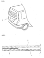
Fig. 1 is a partial perspective view showing a state where a tail gate is mounted to a vehicle; -
Fig. 2 is a sectional view of a related art plastic panel; -
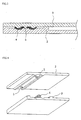
Fig. 3 is a sectional view showing a bonded structure of an embodiment of a plastic panel according to the present invention; -
Fig. 4 is a perspective view of the embodiment of the present invention, in which stoppers are employed; and -
FIGS. 5 to 7 are sectional views illustrating a process of assembling the embodiment of the plastic panel according to the present invention. - Hereinafter, the present invention will be described in detail with reference to the accompanying drawings.
- Inner and
outer panels outer panels 2 may be the same as or different from each other in view of thickness. - In embodiments of the plastic panel of the present invention, at least one
bonding groove 7 in which an adhesive is applied is formed on any one of the inner andouter panels - The other of the inner and
outer panels bonding groove 7 such that the bonding surface can be bonded to the bonding groove using the adhesive 4 applied to the bonding groove. - The bonding surface is shaped as a
protrusion 8 corresponding to a shape of the bonding groove. Even in such a case, it is preferred that a space with a certain interval (gap) be formed between a bottom surface of the protrusion and a floor surface of the bonding groove such that an adhesive can be injected (applied) at a proper thickness in the gap of the space. - Since the plastic panel obtained by mechanically coupling the inner and
outer panels adhesive 4 is applied to thebonding groove 7 formed along an edge of the inner orouter panel - The inner and
outer panels bonding grooves 7 to be formed is determined, a width and depth of the bonding groove can be determined and formed such that the adhesive can be applied to the bonding groove to a suitable bonding area and thickness enough to keep bonding strength to the certain level or more. The bonding area and thickness by which the bonding strength can be maintained after two panels have been bonded may vary according to the kinds of adhesive. However, once the adhesive is selected, bondinggrooves 7 with a width and depth suitable for the selected adhesive can be formed. For example, if a bonding area and thickness of the bonding groove suitable for the kind of selected adhesive is determined, thebonding grooves 7 and the corresponding protrusions, if necessary, enough to ensure the suitable width and thickness are manufactured. Then, a volume of an adhesive to be applied is calculated and the adhesive as much as the calculated volume is applied to the bonding grooves. Therefore, the two panels can be coupled and bonded to each other. At this time, the amount of the adhesive applied is set slightly smaller than the volume of thebonding groove 7 formed between the inner and outer panels, and thus, it is possible to prevent the applied adhesive from leaking out between the bonded panels. - In the present invention, an additional space or
spaces 6 are further formed at one or both sides of the bonding grooves by extending thebonding grooves 7 toward the one or both sides. Therefore, even though the adhesive is injected in the bonding groove more than the volume of the bonding groove, it is possible to prevent the applied adhesive from leaking out between the bonded panels. In a case where the additional spaces are formed at both sides of the bonding grooves, their widths can be different from each other. Further, theadditional spaces 6 can be formed to have the same depth (SeeFIGS. 3 to 7 ). However, the depth of the additional spaces can be gradually decreased away form the bonding groove such that the bonding area per an amount of adhesive applied can be increased. - On the other hand, a stopper can be configured (formed) on the bonding groove or the bonding surface corresponding to the bonding groove to prevent an incomplete bonding state from occurring at the bonded region or prevent the thickness of the applied adhesive from being decreased when the inner and outer panels are pressed and then bonded to each other.
- In embodiments of the present invention, it is most desirable that a thickness (height) of the stopper be equal to the gap between the floor surface of the bonding groove and the bonding surface. However, the height may be slightly less than the gap. Further, a width enough to withstand a bonding pressure applied when the inner and outer panels are bonded and coupled to each other is sufficient for the stopper. Accordingly, it is preferred that the width of the stopper be formed as narrow as possible.
- The
stoppers 5 can be formed on the bonding groove or bonding surface at regular intervals (SeeFIG. 4 ). Alternatively, thestopper 5 can be formed to continuously extend along the bonding groove or bonding surface (not shown). - Further, the
stopper 5 can be separately manufactured and then placed on the bonding surface or bottom surface of thebonding groove 7. Alternatively, the stopper can be formed integrally with the panel. - Since the
stopper 5 is formed, the bonding groove and bonding surface cannot be further pressed. Thus, the two panels can be bonded to each other with a predetermined pressure. Due to the aforementioned structure, therefore, an amount of adhesive used more than necessary can be minimized, and the conventional problem in that the fluid adhesive leaks out between the inner and outer panels and contaminates the exterior of the plastic panel can also be solved. Furthermore, a bonding force can be maximized. - The plastic panel of the present invention can be usefully applied to a vehicle door, in particular, a panel for a tail gate.
- The present invention has the following advantages. That is, since the bonding groove is bonded to the bonding surface of the inner or outer panel, it is possible to prevent the applied adhesive from leaking to the outside. Further, since the bonding groove formed on the inner or outer panel serves as a guide when the adhesive is applied, the adhesive can be applied at a uniform thickness to correct positions even though it is manually applied. Furthermore, since a stopper and additional space are provided on the bonding groove or bonding surface, even an adhesive with certain fluidity cannot leak out between the inner and outer panels. Therefore, the post-processing work for enhancing the external appearance is not required, the manufacturing time and costs can be reduced, and the bonding force can be increased due to the increased bonding area.
Claims (5)
- A plastic panel (1) comprising an inner panel (2) and an outer panel (3), wherein bonding grooves (7) to be coated with adhesive are formed on one of said inner panel and outer panel, and bonding surfaces are formed on the other of said inner panel and outer panel at positions corresponding to said bonding grooves,
characterized in that said bonding surfaces are shaped as protrusions (8) corresponding to shapes of said bonding grooves (7), and stoppers (5) are formed in a space between the bonding protrusions and the bonding grooves,
wherein an additional space or space (6) are further formed at one or both sides of the bonding grooves by extending said bonding grooves (7) toward the one or both sides. - The plastic panel as claimed in claim 1, wherein said bonding grooves (7) are formed on the inner panel (2).
- The plastic panel as claimed in claim 1 or 2, wherein each of said stoppers (5) has a height (thickness) which is equal to or smaller than a gap between said bonding surface and a floor surface of said bonding groove.
- The plastic panel as claimed in claim 1, 2 or 3, wherein said stoppers (5) are formed integrally with said inner (2) or outer (3) panel.
- The plastic panel as claimed in any preceding claim, wherein said plastic panel is used for a vehicle door.
Applications Claiming Priority (3)
| Application Number | Priority Date | Filing Date | Title |
|---|---|---|---|
| KR20050001096 | 2005-01-06 | ||
| KR1020050108550A KR100662101B1 (en) | 2005-01-06 | 2005-11-14 | Plastic panel |
| PCT/KR2006/000029 WO2006073267A1 (en) | 2005-01-06 | 2006-01-04 | Plastic panel |
Publications (3)
| Publication Number | Publication Date |
|---|---|
| EP1833665A1 EP1833665A1 (en) | 2007-09-19 |
| EP1833665A4 EP1833665A4 (en) | 2010-01-13 |
| EP1833665B1 true EP1833665B1 (en) | 2013-03-06 |
Family
ID=36638782
Family Applications (1)
| Application Number | Title | Priority Date | Filing Date |
|---|---|---|---|
| EP06701956A Expired - Lifetime EP1833665B1 (en) | 2005-01-06 | 2006-01-04 | Plastic panel |
Country Status (6)
| Country | Link |
|---|---|
| US (1) | US20060144014A1 (en) |
| EP (1) | EP1833665B1 (en) |
| JP (1) | JP4421616B2 (en) |
| KR (1) | KR100662101B1 (en) |
| CN (1) | CN1942306A (en) |
| WO (1) | WO2006073267A1 (en) |
Families Citing this family (29)
| Publication number | Priority date | Publication date | Assignee | Title |
|---|---|---|---|---|
| JP5004227B2 (en) * | 2007-09-27 | 2012-08-22 | キャタピラー エス エー アール エル | Door panel |
| JP2009133111A (en) * | 2007-11-30 | 2009-06-18 | Caterpillar Japan Ltd | Door panel |
| JP5035776B2 (en) * | 2008-01-22 | 2012-09-26 | ダイキョーニシカワ株式会社 | Resin panel |
| JP5120891B2 (en) * | 2008-08-13 | 2013-01-16 | キャタピラー エス エー アール エル | Door panel |
| US20100074678A1 (en) * | 2008-09-25 | 2010-03-25 | Ford Global Technologies, Llc | Reinforced thermoplastic structural joint assembly for a vehicle |
| US9074418B2 (en) * | 2009-08-12 | 2015-07-07 | Masonite Corporation | Door facing alignment assembly and method of forming a door |
| JP2012147203A (en) * | 2011-01-11 | 2012-08-02 | Smk Corp | Sensor module |
| DE102011001804A1 (en) * | 2011-04-05 | 2012-10-11 | Flamm Ag | Evaporator plate for a chiller |
| CA2774386A1 (en) * | 2011-04-15 | 2012-10-15 | Tac-Fast Systems Canada Limited | Methods and systems for engagement of decorative covering |
| US8926337B2 (en) * | 2012-08-24 | 2015-01-06 | Apple Inc. | Method for improving connector enclosure adhesion |
| US20140272317A1 (en) * | 2013-03-14 | 2014-09-18 | GM Global Technology Operations LLC | Adhesive joint for joining panels |
| US9222269B2 (en) * | 2013-12-19 | 2015-12-29 | National Nail Corp. | Reinforced composite decking and related method of manufacture |
| JP6131971B2 (en) * | 2015-02-23 | 2017-05-24 | トヨタ自動車株式会社 | Panel member joint structure |
| JP6469480B2 (en) * | 2015-03-03 | 2019-02-13 | アクア株式会社 | Refrigerator and manufacturing method thereof |
| US10549789B2 (en) | 2015-09-08 | 2020-02-04 | Wabash National, L.P. | Joining a rail member to a composite trailer structure |
| CN105667270A (en) * | 2015-12-31 | 2016-06-15 | 成都航天模塑股份有限公司 | Connecting structure for automobile plastic tail door |
| PL3865378T3 (en) * | 2017-06-22 | 2024-06-24 | Sika Technology Ag | Connection of vehicle body elements in motor vehicles |
| JP6908473B2 (en) * | 2017-09-04 | 2021-07-28 | 株式会社ミツバ | Fixed structure of touch sensor and touch sensor unit |
| JP6841212B2 (en) * | 2017-11-07 | 2021-03-10 | トヨタ自動車株式会社 | Vehicle doors and manufacturing methods for vehicle doors |
| DE102018211876A1 (en) * | 2018-07-17 | 2020-01-23 | Bayerische Motoren Werke Aktiengesellschaft | Vehicle exterior component |
| JP7211042B2 (en) * | 2018-11-30 | 2023-01-24 | 株式会社リコー | Developer storage container, developing device and image forming apparatus |
| KR102290777B1 (en) * | 2019-10-28 | 2021-08-18 | 주식회사 서연이화 | Adhesive Structure of Resin Tailgate, Bonding method thereof, and Resin Tailgate for Vehicle with same |
| KR102117205B1 (en) * | 2020-02-04 | 2020-05-29 | 김소중 | Pipe buoyancy structure |
| JP7366822B2 (en) * | 2020-03-30 | 2023-10-23 | ダイハツ工業株式会社 | Adhesive structure of resin outer panel |
| US12337903B2 (en) | 2021-03-12 | 2025-06-24 | Wabash National, L.P. | Reinforced preforms for optimized composite structures |
| CN113320360B (en) * | 2021-06-22 | 2023-05-30 | 东风汽车有限公司东风日产乘用车公司 | Resin back door and design method thereof |
| KR102600993B1 (en) * | 2021-07-19 | 2023-11-10 | (주) 세명유리 | Mounting structure of glass panel |
| US12539802B2 (en) | 2021-12-07 | 2026-02-03 | Wabash National, L.P. | Embedded mounting inserts |
| CN118391333B (en) * | 2024-06-20 | 2024-09-03 | 江西省科技基础条件平台中心(江西省计算中心) | Adhesive fixing structure, high-precision sensor and adhesive mounting method thereof |
Family Cites Families (21)
| Publication number | Priority date | Publication date | Assignee | Title |
|---|---|---|---|---|
| DE3331199A1 (en) * | 1983-08-30 | 1985-03-07 | Robert Bosch Gmbh, 7000 Stuttgart | METHOD FOR GLUING SHEETS, DEVICE FOR CARRYING OUT THE METHOD AND USE OF DUROPLASTIC RESIN FOR GLUING SHEETS |
| JPS61130524A (en) * | 1984-11-02 | 1986-06-18 | Nisshoku Corp | Injection work using formwork for slope frame |
| DE3602293A1 (en) | 1986-01-25 | 1987-08-06 | Audi Ag | CONNECTION OF TWO PLASTIC PARTS INCLUDING A CAVITY BY ADHESIVE, IN PARTICULAR FLAP FOR A MOTOR VEHICLE BODY |
| US4798946A (en) * | 1987-04-09 | 1989-01-17 | Mitsubishi Denki Kabushiki Kaisha | Plastic package for an IC card |
| US5102703A (en) * | 1987-12-28 | 1992-04-07 | Kinesis, Inc. | Shock relieving pad |
| JPH0361025A (en) * | 1989-07-28 | 1991-03-15 | Kyoraku Co Ltd | Preparation of multilayer structure |
| JP2594813Y2 (en) * | 1991-09-13 | 1999-05-10 | 旭光学工業株式会社 | Adhesive member |
| US5443673A (en) * | 1992-06-12 | 1995-08-22 | Donnelly Corporation | Vehicular panel assembly and method for making same |
| US5322722A (en) * | 1992-09-04 | 1994-06-21 | Foamade Industries, Inc. | System for adhesively mounting panel liners |
| FR2706573B1 (en) * | 1993-06-11 | 1995-08-25 | Orbey Plastiques Ind | Device for reinforcing hollow parts made of synthetic material, in particular distributors, against deformation or stress. |
| US20040231784A1 (en) * | 1993-10-28 | 2004-11-25 | Lear Corporation | Method for forming plastic molded panels with inserts |
| JPH09125654A (en) * | 1995-10-31 | 1997-05-13 | Fukuvi Chem Ind Co Ltd | Panel and manufacture therefor |
| ES2117549B1 (en) * | 1995-12-13 | 1999-04-01 | Piera Bermejo Antonio | IMPROVEMENTS IN THE MANUFACTURE OF TRANSPARENT PARTS OF PLASTIC MATERIAL WITH INCORPORATED INTERNAL DECORATION. |
| DE19737966A1 (en) * | 1997-08-30 | 1998-08-06 | Daimler Benz Ag | Bonding arrangement for complex composite vehicle structures |
| DE19853773C2 (en) * | 1998-11-21 | 2001-02-22 | Daimler Chrysler Ag | Process for releasably connecting components |
| CA2281297C (en) * | 1999-08-31 | 2003-07-08 | Chia-Ming Chang | Tongue-and-groove floorboard |
| GB0003344D0 (en) * | 2000-02-14 | 2000-04-05 | Lotus Car | A method of joining a first component of a composite material to a second component of a different material |
| DE10016758A1 (en) * | 2000-04-04 | 2001-10-18 | Illbruck Gmbh | Motor vehicle door with insulation element |
| US6439649B1 (en) * | 2001-02-15 | 2002-08-27 | Dow Global Technologies Inc. | Pickup truck box |
| US20030115820A1 (en) * | 2001-12-20 | 2003-06-26 | Mahyar Assadi | Interlocking interference-fit post system for interconnecting thermoplastic platforms |
| DE10246994B3 (en) * | 2002-10-02 | 2004-05-13 | Sai Automotive Sal Gmbh | Automobile bulkhead module for separating engine compartment and passenger compartment has spaced wall skins provided with rib structures which interlock upon shaping of bulkhead module |
-
2005
- 2005-11-14 KR KR1020050108550A patent/KR100662101B1/en not_active Expired - Fee Related
-
2006
- 2006-01-04 JP JP2006550971A patent/JP4421616B2/en not_active Expired - Fee Related
- 2006-01-04 WO PCT/KR2006/000029 patent/WO2006073267A1/en not_active Ceased
- 2006-01-04 CN CNA2006800000236A patent/CN1942306A/en active Pending
- 2006-01-04 EP EP06701956A patent/EP1833665B1/en not_active Expired - Lifetime
- 2006-01-05 US US11/325,866 patent/US20060144014A1/en not_active Abandoned
Also Published As
| Publication number | Publication date |
|---|---|
| KR20060080857A (en) | 2006-07-11 |
| WO2006073267A1 (en) | 2006-07-13 |
| JP2007513016A (en) | 2007-05-24 |
| KR100662101B1 (en) | 2006-12-27 |
| US20060144014A1 (en) | 2006-07-06 |
| EP1833665A1 (en) | 2007-09-19 |
| CN1942306A (en) | 2007-04-04 |
| JP4421616B2 (en) | 2010-02-24 |
| EP1833665A4 (en) | 2010-01-13 |
Similar Documents
| Publication | Publication Date | Title |
|---|---|---|
| US20060144014A1 (en) | Plastic panel | |
| JP5671471B2 (en) | Adhesive bonded composite plastic structural members, methods of manufacturing the same, and structural members manufactured therefrom | |
| EP3490876B1 (en) | Multiple stage deformation reinforcement structure for impact absorption | |
| EP2289769B1 (en) | Structural reinforcer applied to cut-out area of structural member | |
| US7117578B2 (en) | Process for producing a composite component | |
| EP1089870A1 (en) | Reinforcement laminate | |
| US12377619B2 (en) | Edge design of a flat stiffening structure for a component | |
| US20130122246A1 (en) | Structural members and methods of making a structural joint | |
| EP1827817B1 (en) | Improved structural sandwich plate members | |
| KR20150042677A (en) | Fastener | |
| WO2018177388A1 (en) | A Composite Tailgate | |
| EP2212138A1 (en) | Centring pin | |
| KR102826805B1 (en) | Bumper for vehicle and manufacturing method the same | |
| CN115107473A (en) | Window glass assembly and vehicle | |
| US8684436B2 (en) | Intermediate product combination for an internal trim part of a vehicle and internal trim part | |
| US11858322B2 (en) | Frame structure of vehicle | |
| KR101940115B1 (en) | Sunroof panel with thermosetting matter including core material | |
| US10293671B2 (en) | Panel-reinforcement set for a plastic trunk lid | |
| CN221188065U (en) | Vehicle body rear corner window assembly and vehicle | |
| JP7577404B2 (en) | Vehicle door and method for manufacturing vehicle door | |
| CN115195866B (en) | Reinforcing structure for D column connecting joint of automobile body in white | |
| KR200380136Y1 (en) | Concrete form having protection cover | |
| JP2024060206A (en) | Battery case seal structure | |
| JP2021154959A (en) | Adhesive structure of resin outer panel | |
| KR20070095263A (en) | Manufacturing Method of SM Door and SM Door by It |
Legal Events
| Date | Code | Title | Description |
|---|---|---|---|
| PUAI | Public reference made under article 153(3) epc to a published international application that has entered the european phase |
Free format text: ORIGINAL CODE: 0009012 |
|
| 17P | Request for examination filed |
Effective date: 20060619 |
|
| RBV | Designated contracting states (corrected) |
Designated state(s): DE FR GB |
|
| RBV | Designated contracting states (corrected) |
Designated state(s): DE FR GB |
|
| DAX | Request for extension of the european patent (deleted) | ||
| RBV | Designated contracting states (corrected) |
Designated state(s): DE FR GB |
|
| A4 | Supplementary search report drawn up and despatched |
Effective date: 20091210 |
|
| 17Q | First examination report despatched |
Effective date: 20100420 |
|
| GRAP | Despatch of communication of intention to grant a patent |
Free format text: ORIGINAL CODE: EPIDOSNIGR1 |
|
| GRAS | Grant fee paid |
Free format text: ORIGINAL CODE: EPIDOSNIGR3 |
|
| GRAP | Despatch of communication of intention to grant a patent |
Free format text: ORIGINAL CODE: EPIDOSNIGR1 |
|
| GRAA | (expected) grant |
Free format text: ORIGINAL CODE: 0009210 |
|
| AK | Designated contracting states |
Kind code of ref document: B1 Designated state(s): DE FR GB |
|
| REG | Reference to a national code |
Ref country code: GB Ref legal event code: FG4D |
|
| REG | Reference to a national code |
Ref country code: DE Ref legal event code: R096 Ref document number: 602006034890 Country of ref document: DE Effective date: 20130502 |
|
| PLBE | No opposition filed within time limit |
Free format text: ORIGINAL CODE: 0009261 |
|
| STAA | Information on the status of an ep patent application or granted ep patent |
Free format text: STATUS: NO OPPOSITION FILED WITHIN TIME LIMIT |
|
| 26N | No opposition filed |
Effective date: 20131209 |
|
| REG | Reference to a national code |
Ref country code: DE Ref legal event code: R097 Ref document number: 602006034890 Country of ref document: DE Effective date: 20131209 |
|
| REG | Reference to a national code |
Ref country code: DE Ref legal event code: R119 Ref document number: 602006034890 Country of ref document: DE |
|
| GBPC | Gb: european patent ceased through non-payment of renewal fee |
Effective date: 20140104 |
|
| REG | Reference to a national code |
Ref country code: DE Ref legal event code: R119 Ref document number: 602006034890 Country of ref document: DE Effective date: 20140801 |
|
| PG25 | Lapsed in a contracting state [announced via postgrant information from national office to epo] |
Ref country code: DE Free format text: LAPSE BECAUSE OF NON-PAYMENT OF DUE FEES Effective date: 20140801 |
|
| REG | Reference to a national code |
Ref country code: FR Ref legal event code: ST Effective date: 20140930 |
|
| PG25 | Lapsed in a contracting state [announced via postgrant information from national office to epo] |
Ref country code: GB Free format text: LAPSE BECAUSE OF NON-PAYMENT OF DUE FEES Effective date: 20140104 Ref country code: FR Free format text: LAPSE BECAUSE OF NON-PAYMENT OF DUE FEES Effective date: 20140131 |