EP1832833A2 - Heat exchanger unit - Google Patents
Heat exchanger unit Download PDFInfo
- Publication number
- EP1832833A2 EP1832833A2 EP07075127A EP07075127A EP1832833A2 EP 1832833 A2 EP1832833 A2 EP 1832833A2 EP 07075127 A EP07075127 A EP 07075127A EP 07075127 A EP07075127 A EP 07075127A EP 1832833 A2 EP1832833 A2 EP 1832833A2
- Authority
- EP
- European Patent Office
- Prior art keywords
- tubes
- heat exchanger
- section
- manifold
- plane
- Prior art date
- Legal status (The legal status is an assumption and is not a legal conclusion. Google has not performed a legal analysis and makes no representation as to the accuracy of the status listed.)
- Withdrawn
Links
- 239000012530 fluid Substances 0.000 claims abstract description 9
- 230000008014 freezing Effects 0.000 abstract description 5
- 238000007710 freezing Methods 0.000 abstract description 5
- 239000003570 air Substances 0.000 description 21
- 238000010276 construction Methods 0.000 description 9
- 239000003507 refrigerant Substances 0.000 description 5
- 230000002787 reinforcement Effects 0.000 description 5
- 230000005484 gravity Effects 0.000 description 4
- 239000012080 ambient air Substances 0.000 description 2
- 238000007664 blowing Methods 0.000 description 2
- 230000000694 effects Effects 0.000 description 2
- 238000004519 manufacturing process Methods 0.000 description 2
- 239000007787 solid Substances 0.000 description 2
- XLYOFNOQVPJJNP-UHFFFAOYSA-N water Substances O XLYOFNOQVPJJNP-UHFFFAOYSA-N 0.000 description 2
- 238000009825 accumulation Methods 0.000 description 1
- 230000015572 biosynthetic process Effects 0.000 description 1
- 238000005219 brazing Methods 0.000 description 1
- 239000004568 cement Substances 0.000 description 1
- 230000005494 condensation Effects 0.000 description 1
- 238000009833 condensation Methods 0.000 description 1
- 238000009408 flooring Methods 0.000 description 1
- 239000007788 liquid Substances 0.000 description 1
- 238000012986 modification Methods 0.000 description 1
- 230000004048 modification Effects 0.000 description 1
- 238000004806 packaging method and process Methods 0.000 description 1
- 230000002265 prevention Effects 0.000 description 1
- 125000006850 spacer group Chemical group 0.000 description 1
Images



Classifications
-
- F—MECHANICAL ENGINEERING; LIGHTING; HEATING; WEAPONS; BLASTING
- F28—HEAT EXCHANGE IN GENERAL
- F28D—HEAT-EXCHANGE APPARATUS, NOT PROVIDED FOR IN ANOTHER SUBCLASS, IN WHICH THE HEAT-EXCHANGE MEDIA DO NOT COME INTO DIRECT CONTACT
- F28D1/00—Heat-exchange apparatus having stationary conduit assemblies for one heat-exchange medium only, the media being in contact with different sides of the conduit wall, in which the other heat-exchange medium is a large body of fluid, e.g. domestic or motor car radiators
- F28D1/02—Heat-exchange apparatus having stationary conduit assemblies for one heat-exchange medium only, the media being in contact with different sides of the conduit wall, in which the other heat-exchange medium is a large body of fluid, e.g. domestic or motor car radiators with heat-exchange conduits immersed in the body of fluid
- F28D1/04—Heat-exchange apparatus having stationary conduit assemblies for one heat-exchange medium only, the media being in contact with different sides of the conduit wall, in which the other heat-exchange medium is a large body of fluid, e.g. domestic or motor car radiators with heat-exchange conduits immersed in the body of fluid with tubular conduits
- F28D1/053—Heat-exchange apparatus having stationary conduit assemblies for one heat-exchange medium only, the media being in contact with different sides of the conduit wall, in which the other heat-exchange medium is a large body of fluid, e.g. domestic or motor car radiators with heat-exchange conduits immersed in the body of fluid with tubular conduits the conduits being straight
- F28D1/0535—Heat-exchange apparatus having stationary conduit assemblies for one heat-exchange medium only, the media being in contact with different sides of the conduit wall, in which the other heat-exchange medium is a large body of fluid, e.g. domestic or motor car radiators with heat-exchange conduits immersed in the body of fluid with tubular conduits the conduits being straight the conduits having a non-circular cross-section
- F28D1/05366—Assemblies of conduits connected to common headers, e.g. core type radiators
-
- F—MECHANICAL ENGINEERING; LIGHTING; HEATING; WEAPONS; BLASTING
- F28—HEAT EXCHANGE IN GENERAL
- F28F—DETAILS OF HEAT-EXCHANGE AND HEAT-TRANSFER APPARATUS, OF GENERAL APPLICATION
- F28F17/00—Removing ice or water from heat-exchange apparatus
- F28F17/005—Means for draining condensates from heat exchangers, e.g. from evaporators
-
- F—MECHANICAL ENGINEERING; LIGHTING; HEATING; WEAPONS; BLASTING
- F28—HEAT EXCHANGE IN GENERAL
- F28D—HEAT-EXCHANGE APPARATUS, NOT PROVIDED FOR IN ANOTHER SUBCLASS, IN WHICH THE HEAT-EXCHANGE MEDIA DO NOT COME INTO DIRECT CONTACT
- F28D1/00—Heat-exchange apparatus having stationary conduit assemblies for one heat-exchange medium only, the media being in contact with different sides of the conduit wall, in which the other heat-exchange medium is a large body of fluid, e.g. domestic or motor car radiators
- F28D1/02—Heat-exchange apparatus having stationary conduit assemblies for one heat-exchange medium only, the media being in contact with different sides of the conduit wall, in which the other heat-exchange medium is a large body of fluid, e.g. domestic or motor car radiators with heat-exchange conduits immersed in the body of fluid
- F28D2001/0253—Particular components
- F28D2001/026—Cores
- F28D2001/0273—Cores having special shape, e.g. curved, annular
Definitions
- the present invention relates to a heat exchanger unit including a heat exchanger.
- Heat exchanger units are used in a variety of applications that require the transfer of heat from one space to another space.
- the heat exchanger unit includes a heat exchanger and a support assembly for supporting the heat exchanger. Heat transfers from ambient air surrounding the heat exchanger to fluid, i.e. refrigerant, in the heat exchanger.
- the heat exchanger includes a plurality of tubes. The fluid passes through the tubes and heat is transferred from the air surrounding the tubes to the fluid. Fins are generally disposed on the tubes to increase the surface area to the tubes to increase heat transfer from the air surrounding the tubes.
- such a heat exchanger unit is included in a non-mobile heat exchanger system such as a heat pump system.
- the heat pump system transfers heat from an exterior of a building to an interior of the building.
- the heat exchanger unit is disposed in the exterior of the building and heat is transferred from the heat exchanger unit to an interior unit disposed in the interior of the building.
- the heat is dispersed from the interior unit to air in the interior of the building to heat the interior of the building.
- the tubes of the heat exchanger may extend vertically such that the refrigerant flows vertically.
- the tubes of the heat exchanger extend horizontally such that the refrigerant flows horizontally.
- the heat exchanger configured with horizontal tubes is advantageous in the non-mobile heat exchanger unit due to packaging and size restraints.
- the tubes extend between a pair of manifolds.
- each tube has a circular-shaped cross-section.
- the brazed construction typically each tube has a hyper-ellipse-shaped cross-section, i.e. the cross-section is generally rectangular with rounded corners.
- the round tube and plate fin construction is conventionally used in the non-mobile heat exchanger unit. Because the refrigerant is colder than the ambient air flowing around the tubes, condensate forms on the tubes and fins. Because the tubes have the circular-shaped cross-section, the condensate drains from the tubes in response to gravitational force. However, the condensate drains from the tubes along the entire length of the tubes. A large pan is required to collect the drained condensate and to prevent the condensate from draining on water-sensitive components of the heat exchanger unit.
- the brazed construction has better heat transfer properties than the round tube and plate fin construction because brazing improves the thermal contact between the tubes and the fins and the hyper-ellipse-shaped cross-section of the tube creates less air flow resistance than do the round tubes.
- the tubes have the hyper-ellipse-shaped cross-section, condensate does not drain from the tubes in response to gravitational force.
- condensate that forms on a top surface of the hyper-ellipse-shaped cross-section does not drain from the tubes in response to gravitational force.
- the condensate accumulates on the tubes and is subject to freezing on the tubes and fins. Water further accumulates on the tubes and fins in the form of frost. As more condensate forms and freezes on the tubes and fins, the frozen condensate and the frost increases the air flow resistance of the tubes and fins, which leads to a decrease in air flow and heat transfer.
- a heat exchanger unit including a heat exchanger with tubes wherein condensate is drained from the tubes to prevent the accumulation of the condensate on the tubes.
- a heat exchanger unit whereby drained condensate is directed toward a common drainage point to manage the removal of the drained condensate.
- the present invention is a heat exchanger unit comprising a support assembly and a heat exchanger.
- the support assembly has at least one support surface extending in a first plane.
- the heat exchanger is coupled to the support surface and fixed relative to the first plane.
- the heat exchanger includes a first manifold and a second manifold extending in spaced relationship with one another and a plurality of tubes spaced from one another and extending between and engaging the first manifold and the second manifold.
- the tubes communicate fluid between the first manifold and the second manifold. At least a portion of each of the tubes extend angularly relative to the first plane for draining condensate along the tubes toward a common drainage point to remove the condensate from the tubes and focus the condensate to the common drainage point.
- the condensate is drained from the tubes, the condensate does not accumulate on the tubes and the fins.
- the prevention of the condensate from freezing maintains the free movement of air around the tubes of the heat exchanger and maintains the heat transfer capabilities of the heat exchanger.
- the drainage of the condensate toward the common drainage point provides for efficient management of condensate.
- the condensate is drained toward the common drainage point to prevent the splashing or dripping of condensate from the tubes to the support assembly along the length of the tubes.
- the condensate is focused toward the common drainage point and is easily removed from the heat exchanger unit from the common drainage point.
- the heat exchanger unit 20 may be a component of a non-mobile heat exchanger system, such as a heat pump system for a building.
- the heat exchanger unit 20 may be of the type disposed in an exterior of the building.
- heat is transferred from air of the exterior of the building to fluid, i.e. refrigerant, in the heat exchanger unit 20.
- the fluid may then be transferred to an interior unit disposed in an interior of the building where the heat is dispersed from the interior unit to air in the interior of the building to heat the interior of the building.
- the heat exchanger unit 20 includes a support assembly 22 having at least one support surface 24 extending in a first plane 26.
- a heat exchanger 28 is coupled to the support surface 24 and is fixed relative to the first plane 26.
- the support assembly 22 includes a base 30, side panels 32 extending upwardly from the base 30, and a top panel 34.
- the base 30 presents the support surface 24 extending in the first plane 26.
- At least one of the side 32 and the top 34 panels defines a screen 36.
- one of the side and the top panels 32, 34 or any combination of the side panels 32 and/or the top panel 34 defines at least one screen 36.
- the base 30 of the support assembly 22 is configured to rest on a solid surface.
- the base 30 may be disposed on outdoor ground, on a cement slab, or on flooring. It should be appreciated that the base 30 may be disposed on any type of solid surface.
- the base 30 of the support assembly 22 is planar. It should be appreciated that the base 30 may include legs. In such a configuration, the legs present the support surface 24 extending in the first plane 26. It should also be appreciated that the base 30 may include a window mount to be mounted to a window sill of the building. In such a configuration, the heat exchanger unit may be cantilevered from the window mount.
- the base 30 may also include a ceiling mount to be mounted to a ceiling of the building or a wall mount to be mounted to a wall of the building.
- the support assembly 22 is arranged such that the first plane 26 is perpendicular to the direction of gravity.
- the heat exchanger 28 includes a first manifold 38 and a second manifold 40 extending in spaced relationship with one another.
- the heat exchanger 28 includes a plurality of tubes 42 spaced from one another and extending between and engaging the first manifold 38 and the second manifold 40 for communicating fluid between the first manifold 38 and the second manifold 40.
- each of the tubes 42 extends in parallel with one another.
- the panels 32, 34 defining the screen 36 allows the movement of air through the support assembly 22 to facilitate the transfer of heat between the tubes 42 of the heat exchanger 28 and the air moving around the tubes 42.
- fins 44 are disposed on the tubes 42 to increase the surface area of the tubes 42 to increase heat transfer from the air passing around the tubes 42.
- the fins 44 are preferably louvered to increase the surface area of the fins 44 and to increase heat transfer performance.
- the support assembly 22 encloses the heat exchanger 28.
- the heat exchanger unit 20 also includes heat exchanger equipment (not shown) as known to one skilled in the art.
- the support assembly 22 encloses heat exchanger equipment.
- the heat exchanger equipment includes a compressor and an expansion valve.
- the heat exchanger equipment also includes a fan 46 for blowing air over the tubes 42 of the heat exchanger 28.
- the fan 46 is shown as a fan blade.
- the fan blade is shown for illustrative purposes to show the location and the blowing direction of the fan 46 and it should be appreciated that the fan 46 may include any type of fan blade or blower.
- the fan 46 moves air through the support assembly 22.
- the support assembly 22 as shown in Figure 1 is a cuboid, i.e. a rectangular box; however it should be appreciated that the support assembly 22 may be any shape.
- the support assembly 22 may cylindrical.
- the side panels 32 are curved and the tubes 42, as shown in Figure 10, extend along arced paths between the first manifold 38 and the second manifold 40.
- each tube 42 has a hyper-ellipse-shaped cross-section, i.e. the cross-section is generally rectangular with rounded corners.
- each of the tubes 42 has a lower temperature than air surrounding the tubes 42 and fins 44, which may lead to the formation of condensate on the tubes 42 and fins 44.
- At least a portion of each of the tubes 42 extends angularly relative to the first plane 26 for draining condensate along the tubes 42 toward a common drainage point 62 to remove the condensate from the tubes 42 and focus the condensate to the common drainage point 62.
- each tube includes a continuously inclined surface for efficient drainage of condensate.
- the condensate is not subject to freezing on the tubes 42. In other words, in certain conditions the condensate would be subject to freezing on the tube and fins 44 if the condensate was not drained from the tubes 42. Frozen condensate on the tubes 42 would prevent the movement of air around the tubes 42 and the fins 44, which would lead to a decrease in heat transfer.
- the condensate is focused to the common drainage point 62, the condensate is easily managed and drained away from the heat exchanger unit 20. In other words, the condensate is drained toward the common drainage point 62 to prevent the splashing or dripping of condensate from the tubes 42 to the support assembly 22 along the length of the tubes 42.
- a tray (not shown) may be disposed below the common drainage point 62 to collect the condensate. Because the condensate is directed toward the common drainage point 62, the tray need not extend below the tubes 42 along the length of the tubes 42 but rather only below the common drainage point 62.
- the tubes 42 preferably include a first section 48 extending at a first angle A relative to the first plane 26.
- the first angle is greater than or equal to 5 degrees.
- the support assembly 22 is arranged such that the first plane 26 is perpendicular to the direction of gravity.
- the support surface 24 is disposed on a surface that is perpendicular to the direction of gravity.
- the first angle A preferably maximizes the drainage of condensate from the tubes 42 while minimizing unused space in the support assembly 22.
- the support assembly 22 is aesthetically pleasing when the side panels 32 of the support assembly 22 extend upwardly perpendicularly to the first plane 26.
- unused space being generally triangularly-shaped exists above the tubes 42 and below the tubes 42.
- Figure 11 illustrates an effect of varying magnitudes of the first angle A on the air flow resistance of the heat exchanger. For example, as shown in Figure 11, the first angle A having a magnitude of 90 degrees results in the lowest air flow resistance and the first angle A having a magnitude of 0 degrees results in the highest air flow resistance.
- the first angle A may be of any magnitude that maximizes the drainage of condensate from the tubes 42 while minimizing unused space in the support assembly 22.
- the heat exchanger 28 is coupled to the support assembly 22 in any manner known to one skilled in the art.
- the heat exchanger 28 may include a bracket engaging the support assembly 22.
- the bracket may extend from one of the manifolds 38, 40.
- the heat exchanger 28 may include a core reinforcement plate extending between the manifolds 38, 40 and the bracket may extend from the core reinforcement plate.
- the bracket may be sized and shaped to be snapped onto or press-fit onto the manifold or the core reinforcement plate. Alternatively, the bracket may be brazed to the manifold or the core reinforcement plate or may be extruded with the manifold.
- the support assembly 22 may include a plate extending vertically with the bracket extending from the manifold and engaging the plate such that at least a portion of each of the tubes 42 extends angularly relative to the first plane 26.
- the support assembly 22 may include a crossbar extending horizontally with the bracket extending from the core reinforcement plate and engaging the crossbar such that at least a portion of each of the tubes 42 extends angularly relative to the first plane 26.
- the heat exchanger 28 may include a spacer disposed between the base 30 of the support structure and one of the manifolds 38, 40 while the other of the manifolds 38, 40 is disposed on the base 30 of the support structure such that the tubes 42 extend angularly relative to the first plane 26.
- each of the tubes 42 may include sections with a bend between each section. It should be appreciated that the configurations described below are exemplary and the heat exchanger 28 of the present invention may include any number of sections and/or bends. The bends shown in Figures 3-4 and 6-9 are at 90 degrees; however, it should be appreciated that the bends may be at any angle.
- the heat exchanger 28 includes the first section 48.
- each of the tubes 42 extend perpendicularly from the first manifold 38 and from the second manifold 40.
- the common drainage point 62 is located at the first manifold 38.
- condensate on the first section 48 of each of the tubes drains along the first section toward the first manifold 38. When the condensate reaches the first manifold 38, the condensate drips down the first manifold 38 to the common drainage point 62.
- each of the tubes 42 includes a first bend 54 connected to the first section 48 and a second section 50 extending from the first bend 54.
- the first bends 54 of each of the tubes 42 are spaced from one another along a first bend line 58.
- the second section 50 extends perpendicularly relative to the first section 48.
- each of the tubes 42 extend perpendicularly from the first manifold 38 and from the second manifold 40.
- the second section 50 extends at a second angle B relative to the first plane 26.
- the second angle is greater than or equal to 5 degrees.
- the common drainage point 62 is located at the first manifold 38.
- condensate on the second section 50 of each of the tubes 42 drains along the second section 50 toward the first bend 54.
- This condensate at the first bend 54 as well as condensate on the first section 48 drains toward the first manifold 38.
- the condensate drips down the first manifold 38 to the common drainage point 62.
- Figure 2 shows line A which corresponds to the first bend line 58.
- line A extends angularly relative to the first manifold 38.
- line A extends at the first angle A relative to the manifolds 38, 40.
- each of the first bends 54 of the tubes 42 define the first bend line 58 extending perpendicularly relative to the first plane 26.
- each of the tubes 42 includes a second bend 56 connected to the first section 48 and a third section 52 connected to and extending from the second bend 56.
- the second bends 56 of each of the tubes 42 are spaced from one another along a second bend line 60.
- the third section 52 extends perpendicularly relative to the first section 48.
- each of the tubes 42 extend perpendicularly from the first manifold 38 and from the second manifold 40.
- the third section 52 extends at a third angle C relative to the first plane 26.
- the third angle C is greater than or equal to 5 degrees.
- the common drainage point 62 is located at the first manifold 38.
- the condensate on the second section 50 of each of the tubes 42 drains along the second section 50 toward the first bend 54.
- This condensate at the first bend 54 as well as condensate on the first section 48 drains toward the second bend 56.
- This condensate at the second bend 56 as well as the condensate on the third section 52 drains toward the first manifold 38.
- the condensate drips down the first manifold 38 to the common drainage point 62.
- Figure 2 shows line B which corresponds to the second bend line 60.
- line B extends angularly relative to the manifolds.
- line B extends at the second angle B relative to the second manifold 40.
- each of the second bends 56 of the tubes 42 define the second bend line 60 extending perpendicularly relative to the first plane 26.
- the heat exchanger 28 includes the first section 48.
- each of the tubes 42 extend angularly from the first manifold 38 and from the second manifold 40.
- the common drainage point 62 is located at the first manifold 38.
- each of the tubes 42 includes the first bend 54 connected to the first section 48 and the second section 50 extending from the first bend 54.
- the first bends 54 of each of the tubes 42 are spaced from one another along the first bend line 58.
- the second section 50 extends perpendicularly relative to the first section 48.
- Each of the tubes 42 extend angularly from the first manifold 38 and from the second manifold 40.
- the second section 50 extends at a second angle B relative to the first plane 26.
- the common drainage point 62 is located at the first manifold 38.
- Figure 5 shows line C which correspond to the first bend line 58.
- line C extends in parallel with the manifolds 38, 40.
- each of the first bends 54 of the tubes 42 define the first bend line 58 extending perpendicularly relative to the first plane 26. Because the manifolds 38, 40 and the first bend line 58 extend perpendicularly to the first plane 26, the heat exchanger efficiently fits inside the support assembly 22.
- each of the tubes 42 includes a second bend 56 connected to the first section 48 and a third section 52 connected to and extending from the second bend 56.
- the second bends 56 of each of the tubes are spaced from one another along a second bend line 60.
- the third section 52 extends perpendicularly relative to the first section 48.
- each of the tubes 42 extend angularly from the first manifold 38 and from the second manifold 40.
- the third section 52 extends at the third angle C relative to the first plane 26.
- the common drainage point 62 is located at the first manifold 38.
- Figure 5 shows line D which corresponds to the second bend line 60.
- line D extends in parallel with the manifolds 38, 40.
- each of the second bends 56 of the tubes 42 define the second bend line 60 extending perpendicularly relative to the first plane 26. Because the manifolds 38, 40 and the second bend line 58 extend perpendicularly to the first plane 26, the heat exchanger efficiently fits inside the support assembly 22.
- each of the tubes 42 extend perpendicularly from the first manifold 38 and from the second manifold 40.
- Each of the tubes 42 includes the first bend 54 and the second bend 56 with the first section 48 extending between the first bend 54 and the second bend 56.
- the second section 50 extends from the first bend 54 and the third section 52 extends from the second bend 56.
- the first bend line 58, the second bend line 60, the first manifold 38, and the second manifold 40 extend in parallel.
- the second 50 and third 52 sections of each of the tubes 42 extends in parallel with the first plane 26 while maintaining the first section 48 at the first angle A relative to the first plane 26.
- the common drainage point 62 is located at the second bend line 60.
- condensate on each of the tubes 42 of the first section 48 drains along the first section 48 toward the second bend 56.
- the condensate drips down the second bend line 60 to the common drainage point 62.
- each of the tubes 42 extend perpendicularly from the first manifold 38 and from the second manifold 40.
- each of the tubes includes the first section 48, the second section 50, and the third section 52.
- the first section 48 of each of the tubes 42 extends in parallel with the first plane 26.
- the second section 50 of each of the tubes 42 extends from the first bend 54 at the second angle B relative to the first plane 26.
- the third section 52 of each of the tubes 42 extends from the second bend 56 at the third angle C relative to the first plane 26.
- a first common drainage point 64 is located at the first manifold 38 and a second common drainage point 66 is located at the second manifold 40.
- condensate on each of the tubes 42 of the third section 52 drains along the third section 52 toward the first manifold 38. When the condensate reaches the first manifold 38, the condensate drips down the first manifold 38 to the first common drainage point 64.
- Condensate on each of the tubes 42 of the second section 50 drains along the second section 50 toward the second manifold 40.
- the condensate drips down the second manifold 40 to the second common drainage point 66.
Landscapes
- Engineering & Computer Science (AREA)
- Physics & Mathematics (AREA)
- Thermal Sciences (AREA)
- Mechanical Engineering (AREA)
- General Engineering & Computer Science (AREA)
- Heat-Exchange Devices With Radiators And Conduit Assemblies (AREA)
Abstract
A heat exchanger unit (20) includes a support assembly (22) having a support surface (24) extending in a first plane (26) and a heat exchanger (28) coupled to the support surface (24) and fixed relative to the first plane (26). The heat exchanger (28) includes a first manifold (38) and a second manifold (40) extending in spaced relationship with one another and a plurality of tubes (42) spaced from one another and extending between and engaging the first manifold (38) and the second manifold (40). The tubes (42) communicate fluid between the manifolds (38, 40). At least a portion of each of the tubes (42) extend angularly relative to the first plane (26) for draining condensate along the tubes (42) toward a common drainage point (62) to remove the condensate from the tubes (42) and focus the condensate to the common drainage point (62). The drainage of the condensate from the tubes (42) prevents the freezing of the condensate on the tubes (42) to prevent the blockage of air movement over the tubes (42) by frozen condensate.
Description
- The present invention relates to a heat exchanger unit including a heat exchanger.
- Heat exchanger units are used in a variety of applications that require the transfer of heat from one space to another space. Specifically, the heat exchanger unit includes a heat exchanger and a support assembly for supporting the heat exchanger. Heat transfers from ambient air surrounding the heat exchanger to fluid, i.e. refrigerant, in the heat exchanger. Specifically, the heat exchanger includes a plurality of tubes. The fluid passes through the tubes and heat is transferred from the air surrounding the tubes to the fluid. Fins are generally disposed on the tubes to increase the surface area to the tubes to increase heat transfer from the air surrounding the tubes.
- For example, such a heat exchanger unit is included in a non-mobile heat exchanger system such as a heat pump system. The heat pump system transfers heat from an exterior of a building to an interior of the building. Specifically, in such a configuration, the heat exchanger unit is disposed in the exterior of the building and heat is transferred from the heat exchanger unit to an interior unit disposed in the interior of the building. The heat is dispersed from the interior unit to air in the interior of the building to heat the interior of the building.
- The tubes of the heat exchanger may extend vertically such that the refrigerant flows vertically. Alternatively, the tubes of the heat exchanger extend horizontally such that the refrigerant flows horizontally. The heat exchanger configured with horizontal tubes is advantageous in the non-mobile heat exchanger unit due to packaging and size restraints. The tubes extend between a pair of manifolds.
- Two common configurations exist for the heat exchanger, namely, a round tube and plate fin construction and a brazed construction. With respect to the tube-fin construction, typically each tube has a circular-shaped cross-section. With respect to the brazed construction, typically each tube has a hyper-ellipse-shaped cross-section, i.e. the cross-section is generally rectangular with rounded corners.
- The round tube and plate fin construction is conventionally used in the non-mobile heat exchanger unit. Because the refrigerant is colder than the ambient air flowing around the tubes, condensate forms on the tubes and fins. Because the tubes have the circular-shaped cross-section, the condensate drains from the tubes in response to gravitational force. However, the condensate drains from the tubes along the entire length of the tubes. A large pan is required to collect the drained condensate and to prevent the condensate from draining on water-sensitive components of the heat exchanger unit.
- The brazed construction has better heat transfer properties than the round tube and plate fin construction because brazing improves the thermal contact between the tubes and the fins and the hyper-ellipse-shaped cross-section of the tube creates less air flow resistance than do the round tubes. However, because the tubes have the hyper-ellipse-shaped cross-section, condensate does not drain from the tubes in response to gravitational force. In other words, condensate that forms on a top surface of the hyper-ellipse-shaped cross-section does not drain from the tubes in response to gravitational force. The condensate accumulates on the tubes and is subject to freezing on the tubes and fins. Water further accumulates on the tubes and fins in the form of frost. As more condensate forms and freezes on the tubes and fins, the frozen condensate and the frost increases the air flow resistance of the tubes and fins, which leads to a decrease in air flow and heat transfer.
- Accordingly, it would be desirable to manufacture a heat exchanger unit including a heat exchanger with tubes wherein condensate is drained from the tubes to prevent the accumulation of the condensate on the tubes. In addition, it would be desirable to manufacture a heat exchanger unit whereby drained condensate is directed toward a common drainage point to manage the removal of the drained condensate.
- The present invention is a heat exchanger unit comprising a support assembly and a heat exchanger. The support assembly has at least one support surface extending in a first plane. The heat exchanger is coupled to the support surface and fixed relative to the first plane. The heat exchanger includes a first manifold and a second manifold extending in spaced relationship with one another and a plurality of tubes spaced from one another and extending between and engaging the first manifold and the second manifold. The tubes communicate fluid between the first manifold and the second manifold. At least a portion of each of the tubes extend angularly relative to the first plane for draining condensate along the tubes toward a common drainage point to remove the condensate from the tubes and focus the condensate to the common drainage point.
- Accordingly, because the condensate is drained from the tubes, the condensate does not accumulate on the tubes and the fins. The prevention of the condensate from freezing maintains the free movement of air around the tubes of the heat exchanger and maintains the heat transfer capabilities of the heat exchanger.
- In addition, the drainage of the condensate toward the common drainage point provides for efficient management of condensate. In other words, the condensate is drained toward the common drainage point to prevent the splashing or dripping of condensate from the tubes to the support assembly along the length of the tubes. The condensate is focused toward the common drainage point and is easily removed from the heat exchanger unit from the common drainage point.
- Other advantages of the present invention will be readily appreciated, as the same becomes better understood by reference to the following detailed description when considered in connection with the accompanying drawings wherein:
- Figure 1 is a partially cut-away perspective view of the heat exchanger unit including a support assembly presenting a support surface and a first embodiment of a heat exchanger coupled to the support surface;
- Figure 2 is a front view of the first embodiment of the heat exchanger;
- Figure 3 is a perspective view of a second embodiment of the heat exchanger;
- Figure 4 is a perspective view of a third embodiment of the heat exchanger;
- Figure 5 is a front view of a fourth embodiment of the heat exchanger;
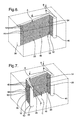
- Figure 6 is a perspective view of a fifth embodiment of the heat exchanger;
- Figure 7 is a perspective view of a sixth embodiment of the heat exchanger;
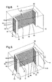
- Figure 8 is a perspective view of a seventh embodiment of the heat exchanger;
- Figure 9 is a perspective view of an eight embodiment of the heat exchanger;
- Figure 10 is a perspective view of a ninth embodiment of the heat exchanger; and
- Figure 11 is a graph illustrating the effect on air flow resistance of an exemplary heat exchanger when tubes of the heat exchanger extend angularly relative to a first plane.
- Referring to the Figures, wherein like numerals indicate corresponding parts throughout the several views, a heat exchanger unit is shown generally at 20. The
heat exchanger unit 20 may be a component of a non-mobile heat exchanger system, such as a heat pump system for a building. In the heat pump system, theheat exchanger unit 20 may be of the type disposed in an exterior of the building. In such a configuration, heat is transferred from air of the exterior of the building to fluid, i.e. refrigerant, in theheat exchanger unit 20. The fluid may then be transferred to an interior unit disposed in an interior of the building where the heat is dispersed from the interior unit to air in the interior of the building to heat the interior of the building. - The
heat exchanger unit 20 includes asupport assembly 22 having at least onesupport surface 24 extending in afirst plane 26. Aheat exchanger 28 is coupled to thesupport surface 24 and is fixed relative to thefirst plane 26. - The
support assembly 22 includes abase 30,side panels 32 extending upwardly from thebase 30, and atop panel 34. The base 30 presents thesupport surface 24 extending in thefirst plane 26. At least one of theside 32 and the top 34 panels defines ascreen 36. In other words, one of the side and thetop panels side panels 32 and/or thetop panel 34 defines at least onescreen 36. - The
base 30 of thesupport assembly 22 is configured to rest on a solid surface. For example, thebase 30 may be disposed on outdoor ground, on a cement slab, or on flooring. It should be appreciated that the base 30 may be disposed on any type of solid surface. As shown in Figure 1, thebase 30 of thesupport assembly 22 is planar. It should be appreciated that the base 30 may include legs. In such a configuration, the legs present thesupport surface 24 extending in thefirst plane 26. It should also be appreciated that the base 30 may include a window mount to be mounted to a window sill of the building. In such a configuration, the heat exchanger unit may be cantilevered from the window mount. It should be appreciated that the base 30 may also include a ceiling mount to be mounted to a ceiling of the building or a wall mount to be mounted to a wall of the building. As will be discussed below, preferably, thesupport assembly 22 is arranged such that thefirst plane 26 is perpendicular to the direction of gravity. - The
heat exchanger 28 includes afirst manifold 38 and asecond manifold 40 extending in spaced relationship with one another. Theheat exchanger 28 includes a plurality oftubes 42 spaced from one another and extending between and engaging thefirst manifold 38 and thesecond manifold 40 for communicating fluid between thefirst manifold 38 and thesecond manifold 40. Preferably, each of thetubes 42 extends in parallel with one another. Thepanels screen 36 allows the movement of air through thesupport assembly 22 to facilitate the transfer of heat between thetubes 42 of theheat exchanger 28 and the air moving around thetubes 42. - Preferably,
fins 44 are disposed on thetubes 42 to increase the surface area of thetubes 42 to increase heat transfer from the air passing around thetubes 42. Thefins 44 are preferably louvered to increase the surface area of thefins 44 and to increase heat transfer performance. - The
support assembly 22 encloses theheat exchanger 28. Theheat exchanger unit 20 also includes heat exchanger equipment (not shown) as known to one skilled in the art. Thesupport assembly 22 encloses heat exchanger equipment. For example, the heat exchanger equipment includes a compressor and an expansion valve. - The heat exchanger equipment also includes a
fan 46 for blowing air over thetubes 42 of theheat exchanger 28. As shown in Figure 1, thefan 46 is shown as a fan blade. The fan blade is shown for illustrative purposes to show the location and the blowing direction of thefan 46 and it should be appreciated that thefan 46 may include any type of fan blade or blower. Thefan 46 moves air through thesupport assembly 22. - The
support assembly 22 as shown in Figure 1 is a cuboid, i.e. a rectangular box; however it should be appreciated that thesupport assembly 22 may be any shape. For example, thesupport assembly 22 may cylindrical. In such a configuration, preferably theside panels 32 are curved and thetubes 42, as shown in Figure 10, extend along arced paths between thefirst manifold 38 and thesecond manifold 40. - Preferably, the
heat exchanger 28 has a brazed construction. Preferably, with respect to the brazed construction, eachtube 42 has a hyper-ellipse-shaped cross-section, i.e. the cross-section is generally rectangular with rounded corners. - The liquid in the
tubes 42 has a lower temperature than air surrounding thetubes 42 andfins 44, which may lead to the formation of condensate on thetubes 42 andfins 44. At least a portion of each of thetubes 42 extends angularly relative to thefirst plane 26 for draining condensate along thetubes 42 toward acommon drainage point 62 to remove the condensate from thetubes 42 and focus the condensate to thecommon drainage point 62. In other words, each tube includes a continuously inclined surface for efficient drainage of condensate. - Because the condensate is drained from the
tubes 42, the condensate is not subject to freezing on thetubes 42. In other words, in certain conditions the condensate would be subject to freezing on the tube andfins 44 if the condensate was not drained from thetubes 42. Frozen condensate on thetubes 42 would prevent the movement of air around thetubes 42 and thefins 44, which would lead to a decrease in heat transfer. - Because the condensate is focused to the
common drainage point 62, the condensate is easily managed and drained away from theheat exchanger unit 20. In other words, the condensate is drained toward thecommon drainage point 62 to prevent the splashing or dripping of condensate from thetubes 42 to thesupport assembly 22 along the length of thetubes 42. For example, a tray (not shown) may be disposed below thecommon drainage point 62 to collect the condensate. Because the condensate is directed toward thecommon drainage point 62, the tray need not extend below thetubes 42 along the length of thetubes 42 but rather only below thecommon drainage point 62. - Specifically, the
tubes 42 preferably include afirst section 48 extending at a first angle A relative to thefirst plane 26. Preferably, the first angle is greater than or equal to 5 degrees. - Preferably, the
support assembly 22 is arranged such that thefirst plane 26 is perpendicular to the direction of gravity. In other words, preferably thesupport surface 24 is disposed on a surface that is perpendicular to the direction of gravity. When thefirst plane 26 is perpendicular to the direction of gravity, gravitational forces act on the condensate to move the condensate along thefirst section 48 of thetubes 42. - The first angle A preferably maximizes the drainage of condensate from the
tubes 42 while minimizing unused space in thesupport assembly 22. In other words, thesupport assembly 22 is aesthetically pleasing when theside panels 32 of thesupport assembly 22 extend upwardly perpendicularly to thefirst plane 26. In such a configuration, when thetubes 42 extend at the first angle A relative to thefirst plane 26, unused space being generally triangularly-shaped exists above thetubes 42 and below thetubes 42. Figure 11 illustrates an effect of varying magnitudes of the first angle A on the air flow resistance of the heat exchanger. For example, as shown in Figure 11, the first angle A having a magnitude of 90 degrees results in the lowest air flow resistance and the first angle A having a magnitude of 0 degrees results in the highest air flow resistance. In other words, as the magnitude of the first angle A is increased, the condensation is better drained from the tubes resulting in a decrease in air flow resistance of the heat exchanger. When the first angle A has a magnitude of 5 degrees, the increase in pressure differential across the heat exchanger resulting from the first angle A being 0 degrees is reduced by approximately half. However, it should be appreciated that the first angle A may be of any magnitude that maximizes the drainage of condensate from thetubes 42 while minimizing unused space in thesupport assembly 22. - The
heat exchanger 28 is coupled to thesupport assembly 22 in any manner known to one skilled in the art. For example, theheat exchanger 28 may include a bracket engaging thesupport assembly 22. The bracket may extend from one of themanifolds heat exchanger 28 may include a core reinforcement plate extending between themanifolds - The bracket may be sized and shaped to be snapped onto or press-fit onto the manifold or the core reinforcement plate. Alternatively, the bracket may be brazed to the manifold or the core reinforcement plate or may be extruded with the manifold.
- For example, the
support assembly 22 may include a plate extending vertically with the bracket extending from the manifold and engaging the plate such that at least a portion of each of thetubes 42 extends angularly relative to thefirst plane 26. In another configuration, for example, thesupport assembly 22 may include a crossbar extending horizontally with the bracket extending from the core reinforcement plate and engaging the crossbar such that at least a portion of each of thetubes 42 extends angularly relative to thefirst plane 26. - In the alternative to or in addition to the bracket, the
heat exchanger 28 may include a spacer disposed between the base 30 of the support structure and one of themanifolds manifolds base 30 of the support structure such that thetubes 42 extend angularly relative to thefirst plane 26. - In differing configurations described below, each of the
tubes 42 may include sections with a bend between each section. It should be appreciated that the configurations described below are exemplary and theheat exchanger 28 of the present invention may include any number of sections and/or bends. The bends shown in Figures 3-4 and 6-9 are at 90 degrees; however, it should be appreciated that the bends may be at any angle. - In a first embodiment of the heat exchanger, as shown in Figures 1 and 2, the
heat exchanger 28 includes thefirst section 48. In the first embodiment, each of thetubes 42 extend perpendicularly from thefirst manifold 38 and from thesecond manifold 40. In the first embodiment, thecommon drainage point 62 is located at thefirst manifold 38. In other words, condensate on thefirst section 48 of each of the tubes drains along the first section toward thefirst manifold 38. When the condensate reaches thefirst manifold 38, the condensate drips down thefirst manifold 38 to thecommon drainage point 62. - In a second embodiment of the heat exchanger, as shown in Figure 3, each of the
tubes 42 includes afirst bend 54 connected to thefirst section 48 and asecond section 50 extending from thefirst bend 54. The first bends 54 of each of thetubes 42 are spaced from one another along afirst bend line 58. Preferably, thesecond section 50 extends perpendicularly relative to thefirst section 48. As in the first embodiment, each of thetubes 42 extend perpendicularly from thefirst manifold 38 and from thesecond manifold 40. - In the second embodiment, the
second section 50 extends at a second angle B relative to thefirst plane 26. Preferably, the second angle is greater than or equal to 5 degrees. - In the second embodiment, the
common drainage point 62 is located at thefirst manifold 38. In other words, condensate on thesecond section 50 of each of thetubes 42 drains along thesecond section 50 toward thefirst bend 54. This condensate at thefirst bend 54 as well as condensate on thefirst section 48 drains toward thefirst manifold 38. When the condensate reaches thefirst manifold 38, the condensate drips down thefirst manifold 38 to thecommon drainage point 62. - For illustrative purposes, Figure 2 shows line A which corresponds to the
first bend line 58. Specifically, line A extends angularly relative to thefirst manifold 38. Preferably, line A extends at the first angle A relative to themanifolds first section 48 extends at the first angle A relative to thefirst plane 26 and thesecond section 50 extends at the second angle B relative to thefirst plane 26, each of the first bends 54 of thetubes 42 define thefirst bend line 58 extending perpendicularly relative to thefirst plane 26. - In a third embodiment of the heat exchanger, as shown in Figure 4, each of the
tubes 42 includes asecond bend 56 connected to thefirst section 48 and athird section 52 connected to and extending from thesecond bend 56. The second bends 56 of each of thetubes 42 are spaced from one another along asecond bend line 60. Preferably, thethird section 52 extends perpendicularly relative to thefirst section 48. As in the first and second embodiments, each of thetubes 42 extend perpendicularly from thefirst manifold 38 and from thesecond manifold 40. - The
third section 52 extends at a third angle C relative to thefirst plane 26. Preferably, the third angle C is greater than or equal to 5 degrees. - As shown in Figure 4, the
common drainage point 62 is located at thefirst manifold 38. In other words, the condensate on thesecond section 50 of each of thetubes 42 drains along thesecond section 50 toward thefirst bend 54. This condensate at thefirst bend 54 as well as condensate on thefirst section 48 drains toward thesecond bend 56. This condensate at thesecond bend 56 as well as the condensate on thethird section 52 drains toward thefirst manifold 38. When the condensate reaches thefirst manifold 38, the condensate drips down thefirst manifold 38 to thecommon drainage point 62. - For illustrative purposes, Figure 2 shows line B which corresponds to the
second bend line 60. Specifically, line B extends angularly relative to the manifolds. Preferably, line B extends at the second angle B relative to thesecond manifold 40. In such a configuration, when thefirst section 48 extends at the first angle A relative to thefirst plane 26 and thethird section 52 extends at the third angle C relative to thefirst plane 26, each of the second bends 56 of thetubes 42 define thesecond bend line 60 extending perpendicularly relative to thefirst plane 26. - In a fourth embodiment of the heat exchanger, as shown in Figure 5, the
heat exchanger 28 includes thefirst section 48. In the fourth embodiment, each of thetubes 42 extend angularly from thefirst manifold 38 and from thesecond manifold 40. As in the first embodiment, in the fourth embodiment thecommon drainage point 62 is located at thefirst manifold 38. - In a fifth embodiment of the heat exchanger, as shown in Figure 6, each of the
tubes 42 includes thefirst bend 54 connected to thefirst section 48 and thesecond section 50 extending from thefirst bend 54. The first bends 54 of each of thetubes 42 are spaced from one another along thefirst bend line 58. Preferably, thesecond section 50 extends perpendicularly relative to thefirst section 48. Each of thetubes 42 extend angularly from thefirst manifold 38 and from thesecond manifold 40. - In the fifth embodiment, as in the second embodiment, the
second section 50 extends at a second angle B relative to thefirst plane 26. In the fifth embodiment, as in the second embodiment, thecommon drainage point 62 is located at thefirst manifold 38. - For illustrative purposes, Figure 5 shows line C which correspond to the
first bend line 58. Specifically, line C extends in parallel with themanifolds first section 48 extends at the first angle A relative to thefirst plane 26 and thesecond section 50 extends at the second angle B relative to thefirst plane 26, each of the first bends 54 of thetubes 42 define thefirst bend line 58 extending perpendicularly relative to thefirst plane 26. Because themanifolds first bend line 58 extend perpendicularly to thefirst plane 26, the heat exchanger efficiently fits inside thesupport assembly 22. - In a sixth embodiment of the heat exchanger, as shown in Figure 7, each of the
tubes 42 includes asecond bend 56 connected to thefirst section 48 and athird section 52 connected to and extending from thesecond bend 56. The second bends 56 of each of the tubes are spaced from one another along asecond bend line 60. Preferably, thethird section 52 extends perpendicularly relative to thefirst section 48. As in the fourth and fifth embodiments, each of thetubes 42 extend angularly from thefirst manifold 38 and from thesecond manifold 40. - In the sixth embodiment, as in the third embodiment, the
third section 52 extends at the third angle C relative to thefirst plane 26. In the sixth embodiment, as in the third embodiment, thecommon drainage point 62 is located at thefirst manifold 38. - For illustrative purposes, Figure 5 shows line D which corresponds to the
second bend line 60. Specifically, line D extends in parallel with themanifolds first section 48 extends at the first angle A relative to thefirst plane 26 and thethird section 52 extends at the third angle C relative to thefirst plane 26, each of the second bends 56 of thetubes 42 define thesecond bend line 60 extending perpendicularly relative to thefirst plane 26. Because themanifolds second bend line 58 extend perpendicularly to thefirst plane 26, the heat exchanger efficiently fits inside thesupport assembly 22. - In a seventh embodiment of the heat exchanger, as shown in Figure 8, each of the
tubes 42 extend perpendicularly from thefirst manifold 38 and from thesecond manifold 40. Each of thetubes 42 includes thefirst bend 54 and thesecond bend 56 with thefirst section 48 extending between thefirst bend 54 and thesecond bend 56. Thesecond section 50 extends from thefirst bend 54 and thethird section 52 extends from thesecond bend 56. Thefirst bend line 58, thesecond bend line 60, thefirst manifold 38, and thesecond manifold 40 extend in parallel. - As shown in Figure 8, the second 50 and third 52 sections of each of the
tubes 42 extends in parallel with thefirst plane 26 while maintaining thefirst section 48 at the first angle A relative to thefirst plane 26. In the seventh embodiment, thecommon drainage point 62 is located at thesecond bend line 60. In other words, condensate on each of thetubes 42 of thefirst section 48 drains along thefirst section 48 toward thesecond bend 56. When the condensate reaches thesecond bend 56, the condensate drips down thesecond bend line 60 to thecommon drainage point 62. - In an eighth embodiment of the heat exchanger, as shown in Figure 9, each of the
tubes 42 extend perpendicularly from thefirst manifold 38 and from thesecond manifold 40. In the eighth embodiment, as in the seventh embodiment, each of the tubes includes thefirst section 48, thesecond section 50, and thethird section 52. - In the eighth embodiment, the
first section 48 of each of thetubes 42 extends in parallel with thefirst plane 26. Thesecond section 50 of each of thetubes 42 extends from thefirst bend 54 at the second angle B relative to thefirst plane 26. Thethird section 52 of each of thetubes 42 extends from thesecond bend 56 at the third angle C relative to thefirst plane 26. A firstcommon drainage point 64 is located at thefirst manifold 38 and a secondcommon drainage point 66 is located at thesecond manifold 40. In other words, condensate on each of thetubes 42 of thethird section 52 drains along thethird section 52 toward thefirst manifold 38. When the condensate reaches thefirst manifold 38, the condensate drips down thefirst manifold 38 to the firstcommon drainage point 64. Condensate on each of thetubes 42 of thesecond section 50 drains along thesecond section 50 toward thesecond manifold 40. When the condensate reaches thesecond manifold 40, the condensate drips down thesecond manifold 40 to the secondcommon drainage point 66. - The invention has been described in an illustrative manner, and it is to be understood that the terminology which has been used is intended to be in the nature of words of description rather than of limitation. Obviously, many modifications and variations of the present invention are possible in light of the above teachings, and the invention may be practiced otherwise than as specifically described.
Claims (20)
- A heat exchanger unit (20) comprising;a support assembly (22) having at least one support surface (24) extending in a first plane (26),a heat exchanger (20) coupled to said support surface (24) and fixed relative to said first plane (26) with said heat exchanger (20) including;a first manifold (38) and a second manifold (40) extending in spaced relationship with one another, anda plurality of tubes (42) spaced from one another and extending between and engaging said first manifold (38) and said second manifold (40) for communicating fluid between said first manifold (38) and said second manifold (40),at least a portion of each of said tubes (42) extending angularly relative to said first plane (26) for draining condensate along said tubes (42) toward a common drainage point (62) to remove the condensate from the tubes (42) and focus the condensate to the common drainage point (62).
- The heat exchanger unit (20) as set forth in claim 1 wherein said tubes (42) include a first section (48) extending at a first angle (A) relative to said first plane (26).
- The heat exchanger unit (20) as set forth in claim 2 wherein said first angle (A) is greater than or equal to 5 degrees.
- The heat exchanger unit (20) as set forth in claim 2 wherein each of said tubes (42) includes a first bend (54) connected to said first section (48) and a second section (50) extending from said first bend (54).
- The heat exchanger unit (20) as set forth in claim 4 wherein said second section (50) extends perpendicularly relative to said first section (48).
- The heat exchanger unit (20) as set forth in claim 4 wherein said second section (50) extends at a second angle (B) relative to said first plane (26).
- The heat exchanger unit (20) as set forth in claim 6 wherein said second angle (B) is greater than or equal to 5 degrees.
- The heat exchanger unit (20) as set forth in claim 4 wherein each of said tubes (42) includes a second bend (56) connected to said first section (48) and a third section (52) connected to and extending from said second bend (56).
- The heat exchanger unit (20) as set forth in claim 8 wherein said third section (52) extends perpendicularly relative to said first section (48).
- The heat exchanger unit (20) as set forth in claim 8 wherein said third section (52) extends at a third angle (C) relative to said first plane (26).
- The heat exchanger unit (20) as set forth in claim 10 wherein said third angle (C) is greater than or equal to five degrees.
- The heat exchanger unit (20) as set forth in claim 4 wherein each of said first bends (54) of said tubes (42) define a first bend line (58) extending perpendicularly relative to said first plane (26).
- The heat exchanger unit (20) as set forth in claim 8 wherein each of said first bends (54) of said tubes (42) define a first bend line (58) extending perpendicularly relative to said first plane (26) and each of said second bends (56) of said tubes (42) define a second bend line (60) extending perpendicularly relative to said first plane (26).
- The heat exchanger unit (20) as set forth in claim 4 wherein said second section (50) of each of said tubes (42) extends in parallel with said first plane (26) while maintaining said first section (48) at said first angle (A) relative to said first plane (26).
- The heat exchanger unit (20) as set forth in claim 8 wherein said second section (50) of each of said tubes (42) extends in parallel with said first plane (26) and said third section (52) of each of said tubes (42) extend in parallel with said first plane (26) while maintaining said first section (48) at said first angle (A) relative to said first plane (26).
- The heat exchanger unit (20) as set forth in claim 1 wherein each of said tubes (42) includes a first bend (54) and a second bend (56) with a first section (48) extending between said first bend (54) and said second bend (56) in parallel with said first plane (26), a second section (50) extending from said first bend (54) at a second angle (B) relative to said first plane (26), and a third section (52) extending from said second bend (56) at a third angle (C) relative to said first plane (26).
- The heat exchanger unit (20) as set forth in claim 1 wherein each of said tubes (42) extend perpendicularly from said first manifold (38) and from said second manifold (40).
- The heat exchanger unit (20) as set forth in claim 1 wherein said tubes (42) extend angularly from said first manifold (38) and from said second manifold (40).
- The heat exchanger unit (20) as set forth in claim 1 wherein each of said tubes (42) extend in parallel with one another.
- The heat exchanger unit (20) as set forth in claim 1 wherein said tubes (42) extend along arced paths between said first manifold (38) and said second manifold (40).
Applications Claiming Priority (2)
| Application Number | Priority Date | Filing Date | Title |
|---|---|---|---|
| US77963106P | 2006-03-06 | 2006-03-06 | |
| US11/599,839 US20070204978A1 (en) | 2006-03-06 | 2006-11-15 | Heat exchanger unit |
Publications (1)
| Publication Number | Publication Date |
|---|---|
| EP1832833A2 true EP1832833A2 (en) | 2007-09-12 |
Family
ID=38121901
Family Applications (1)
| Application Number | Title | Priority Date | Filing Date |
|---|---|---|---|
| EP07075127A Withdrawn EP1832833A2 (en) | 2006-03-06 | 2007-02-13 | Heat exchanger unit |
Country Status (2)
| Country | Link |
|---|---|
| US (1) | US20070204978A1 (en) |
| EP (1) | EP1832833A2 (en) |
Cited By (7)
| Publication number | Priority date | Publication date | Assignee | Title |
|---|---|---|---|---|
| WO2017064531A1 (en) * | 2015-10-12 | 2017-04-20 | Carrier Corporation | Heat exchanger for residential hvac applications |
| WO2018036468A1 (en) * | 2016-08-26 | 2018-03-01 | 丹佛斯微通道换热器(嘉兴)有限公司 | Heat exchanger, heat exchanger module, and air conditioning system |
| EP3139113A4 (en) * | 2014-04-18 | 2018-03-14 | Danfoss Micro Channel Heat Exchanger (Tianjin) Co.,Ltd. | Heat exchanger and manufacturing method therefor, heat exchange module, heat exchange device, and heat source unit |
| US11277939B2 (en) | 2019-01-22 | 2022-03-15 | Hitachi Energy Switzerland Ag | Evaporator and manufacturing method |
| EP3232148B1 (en) * | 2014-12-11 | 2023-05-10 | Danfoss Micro Channel Heat Exchanger (Jiaxing) Co., Ltd | Heat exchanger, heat exchange module, heat exchange device, and heat source unit |
| US11656011B2 (en) | 2019-01-22 | 2023-05-23 | Hitachi Energy Switzerland Ag | Condenser |
| EP4443093A4 (en) * | 2021-11-29 | 2025-12-03 | Danfoss As | HEAT EXCHANGER ASSEMBLY AND AIR CONDITIONING SO THAT |
Families Citing this family (22)
| Publication number | Priority date | Publication date | Assignee | Title |
|---|---|---|---|---|
| US20070204977A1 (en) * | 2006-03-06 | 2007-09-06 | Henry Earl Beamer | Heat exchanger for stationary air conditioning system with improved water condensate drainage |
| DE102006019024A1 (en) * | 2006-04-25 | 2007-10-31 | Modine Manufacturing Co., Racine | Heat exchangers for motor vehicles |
| KR101568200B1 (en) * | 2006-11-22 | 2015-11-11 | 존슨 컨트롤스 테크놀러지 컴퍼니 | Multichannel heat exchanger with dissimilar tube spacing |
| US8307669B2 (en) * | 2007-02-27 | 2012-11-13 | Carrier Corporation | Multi-channel flat tube evaporator with improved condensate drainage |
| WO2009018150A1 (en) | 2007-07-27 | 2009-02-05 | Johnson Controls Technology Company | Multichannel heat exchanger |
| US20110139425A1 (en) * | 2009-12-15 | 2011-06-16 | Delphi Technologies, Inc. | Two row bent evaporator |
| JP2011185562A (en) * | 2010-03-10 | 2011-09-22 | Showa Denko Kk | Condenser |
| JP5549309B2 (en) * | 2010-03-26 | 2014-07-16 | 株式会社デンソー | Air conditioner |
| US20120227944A1 (en) * | 2011-03-10 | 2012-09-13 | Theodor Moisidis | Bent tube heat exchanger assembly |
| CN103759553B (en) * | 2014-02-17 | 2016-05-11 | 丹佛斯微通道换热器(嘉兴)有限公司 | Heat exchange device and heat source unit |
| US10197313B2 (en) * | 2014-05-09 | 2019-02-05 | Samwon Industrial Co., Ltd. | Condenser for refrigerator |
| US9557082B1 (en) * | 2014-05-13 | 2017-01-31 | Sa Vent, Llc | Apparatus for converting hot air and steam emissions into cooler air and condensate |
| JP6471345B2 (en) * | 2014-05-29 | 2019-02-20 | パナソニックIpマネジメント株式会社 | Heat exchanger |
| US20170067655A1 (en) * | 2015-09-08 | 2017-03-09 | General Electric Company | Air conditioner units having improved apparatus for providing make-up air |
| CN106918166B (en) | 2015-12-24 | 2023-03-03 | 丹佛斯微通道换热器(嘉兴)有限公司 | Heat exchanger and air conditioning system |
| CN107388637B (en) * | 2016-05-16 | 2023-04-28 | 丹佛斯微通道换热器(嘉兴)有限公司 | Heat exchanger and heat exchange module |
| USD910821S1 (en) | 2016-08-26 | 2021-02-16 | Danfoss Micro Channel Heat Exchanger (Jiaxing) Co., Ltd. | Heat exchanger |
| WO2018073898A1 (en) * | 2016-10-18 | 2018-04-26 | 三菱電機株式会社 | Heat exchanger, outdoor unit, and manufacturing device and manufacturing method for heat exchanger |
| JP1615400S (en) * | 2017-08-21 | 2018-10-09 | ||
| KR20190032106A (en) * | 2017-09-19 | 2019-03-27 | 엘지전자 주식회사 | Heat exchanger |
| AT525742B1 (en) * | 2022-06-08 | 2023-07-15 | Ktm Ag | cooler |
| CN115143667A (en) * | 2022-07-15 | 2022-10-04 | 东富龙科技集团股份有限公司 | A cylindrical microchannel refrigeration evaporator |
Family Cites Families (24)
| Publication number | Priority date | Publication date | Assignee | Title |
|---|---|---|---|---|
| US3724426A (en) * | 1971-04-14 | 1973-04-03 | V Brown | Hydrothermal liquefied petroleum gas vaporization system |
| US3882690A (en) * | 1973-09-28 | 1975-05-13 | Carrier Corp | Heat exchange assembly |
| US4159802A (en) * | 1978-05-22 | 1979-07-03 | Herman Ficker | Heating system utilizing fuel bearing multi-tube water jacket |
| JPS5958631U (en) * | 1982-10-13 | 1984-04-17 | 本田技研工業株式会社 | motorcycle heat exchanger |
| US4449377A (en) * | 1983-03-14 | 1984-05-22 | Westinghouse Electric Corp. | Thermosyphon coil arrangement for heat pump outdoor unit |
| US5279360A (en) * | 1985-10-02 | 1994-01-18 | Modine Manufacturing Co. | Evaporator or evaporator/condenser |
| US4958500A (en) * | 1989-04-20 | 1990-09-25 | Hitachi, Ltd. | Air conditioner and air conditioning method |
| US4958681A (en) * | 1989-08-14 | 1990-09-25 | General Motors Corporation | Heat exchanger with bypass channel louvered fins |
| US5062280B1 (en) * | 1990-10-31 | 1999-12-14 | Allstyle Coil Co Inc | Air conditioning apparatus |
| US5121613A (en) * | 1991-01-08 | 1992-06-16 | Rheem Manufacturing Company | Compact modular refrigerant coil apparatus and associated manufacturing methods |
| US5062476A (en) * | 1991-02-28 | 1991-11-05 | General Motors Corporation | Heat exchanger with an extruded tank |
| US5755107A (en) * | 1994-09-22 | 1998-05-26 | Denso Corporation | Automotive air conditioner |
| US5669438A (en) * | 1996-08-30 | 1997-09-23 | General Motors Corporation | Corrugated cooling fin with louvers |
| KR100214639B1 (en) * | 1996-12-21 | 1999-08-02 | 구자홍 | Top suction cross flow type indoor unit of air conditioner |
| US5826649A (en) * | 1997-01-24 | 1998-10-27 | Modine Manufacturing Co. | Evaporator, condenser for a heat pump |
| US5950446A (en) * | 1998-10-01 | 1999-09-14 | Whirlpool Corporation | Compact air conditioner |
| DE19918616C2 (en) * | 1998-10-27 | 2001-10-31 | Valeo Klimatechnik Gmbh | Condenser for condensing the internal refrigerant of an automotive air conditioning system |
| US6116335A (en) * | 1999-08-30 | 2000-09-12 | Delphi Technologies, Inc. | Fluid flow heat exchanger with reduced pressure drop |
| US6439300B1 (en) * | 1999-12-21 | 2002-08-27 | Delphi Technologies, Inc. | Evaporator with enhanced condensate drainage |
| ES2250344T3 (en) * | 2000-01-14 | 2006-04-16 | Toshiba Carrier Corporation | OUTDOOR UNIT OF AN AIR CONDITIONER. |
| US6264464B1 (en) * | 2000-05-12 | 2001-07-24 | Megtec Systems, Inc. | Angled bed for regenerative heat exchanger |
| US6877550B2 (en) * | 2000-07-21 | 2005-04-12 | Denso Corporation | Vehicle air conditioner |
| US6880620B2 (en) * | 2002-06-25 | 2005-04-19 | Delphi Technologies, Inc. | Heating, ventilating, and air conditioning module having an improved heater core configuration |
| US6672375B1 (en) * | 2002-07-02 | 2004-01-06 | American Standard International Inc. | Fin tube heat exchanger with divergent tube rows |
-
2006
- 2006-11-15 US US11/599,839 patent/US20070204978A1/en not_active Abandoned
-
2007
- 2007-02-13 EP EP07075127A patent/EP1832833A2/en not_active Withdrawn
Cited By (10)
| Publication number | Priority date | Publication date | Assignee | Title |
|---|---|---|---|---|
| EP3139113A4 (en) * | 2014-04-18 | 2018-03-14 | Danfoss Micro Channel Heat Exchanger (Tianjin) Co.,Ltd. | Heat exchanger and manufacturing method therefor, heat exchange module, heat exchange device, and heat source unit |
| US10030912B2 (en) | 2014-04-18 | 2018-07-24 | Danfoss Micro Channel Heat Exchanger (Jiaxing) Co., Ltd. | Heat exchanger and manufacturing method therefor, heat exchange module, heat exchange device, and heat source unit |
| EP3232148B1 (en) * | 2014-12-11 | 2023-05-10 | Danfoss Micro Channel Heat Exchanger (Jiaxing) Co., Ltd | Heat exchanger, heat exchange module, heat exchange device, and heat source unit |
| WO2017064531A1 (en) * | 2015-10-12 | 2017-04-20 | Carrier Corporation | Heat exchanger for residential hvac applications |
| WO2018036468A1 (en) * | 2016-08-26 | 2018-03-01 | 丹佛斯微通道换热器(嘉兴)有限公司 | Heat exchanger, heat exchanger module, and air conditioning system |
| EP3505848A4 (en) * | 2016-08-26 | 2020-05-27 | Danfoss Micro Channel Heat Exchanger (Jiaxing) Co. Ltd. | HEAT EXCHANGER, HEAT EXCHANGER MODULE AND AIR CONDITIONING SYSTEM |
| US11609024B2 (en) | 2016-08-26 | 2023-03-21 | Danfoss Micro Channel Heat Exchanger (Jiaxing) Co., Ltd. | Heat exchanger, heat exchanger module, and air conditioning system |
| US11277939B2 (en) | 2019-01-22 | 2022-03-15 | Hitachi Energy Switzerland Ag | Evaporator and manufacturing method |
| US11656011B2 (en) | 2019-01-22 | 2023-05-23 | Hitachi Energy Switzerland Ag | Condenser |
| EP4443093A4 (en) * | 2021-11-29 | 2025-12-03 | Danfoss As | HEAT EXCHANGER ASSEMBLY AND AIR CONDITIONING SO THAT |
Also Published As
| Publication number | Publication date |
|---|---|
| US20070204978A1 (en) | 2007-09-06 |
Similar Documents
| Publication | Publication Date | Title |
|---|---|---|
| US20070204978A1 (en) | Heat exchanger unit | |
| JP5464207B2 (en) | Refrigeration unit outdoor unit | |
| CN102959353B (en) | Multi-channel tubes with deformable partitions | |
| EP1832831A2 (en) | Heat exchanger for stationary air conditioning system with improved water condensate drainage | |
| US20100071868A1 (en) | Hvac units, heat exchangers, buildings, and methods having slanted fins to shed condensation or for improved air flow | |
| JP5009413B2 (en) | Heat exchanger and air conditioner equipped with the same | |
| CN107003016A (en) | The outdoor unit | |
| JP5398283B2 (en) | Air conditioner outdoor unit | |
| MXPA02001274A (en) | Air conditioning unit having coil portion with non-uniform fin arrangement. | |
| WO2018235215A1 (en) | Heat exchanger, refrigeration cycle device, and air conditioner | |
| JP6826805B2 (en) | Outdoor unit of refrigeration equipment | |
| CN203798027U (en) | Heat exchanger and refrigerating cycle air conditioner using the heat exchanger | |
| JP6332377B2 (en) | Heat exchanger | |
| US11118796B2 (en) | Outdoor unit for air conditioner | |
| JP2018197634A (en) | Heat exchanger | |
| JPWO2020012549A1 (en) | Heat exchanger, heat exchanger unit and refrigeration cycle device | |
| JP7353483B2 (en) | Heat exchanger and air conditioner equipped with the heat exchanger | |
| US12595975B2 (en) | Heat exchanger | |
| JP2018162953A (en) | Heat exchanger | |
| KR20100084402A (en) | Air conditioner | |
| JP6954429B2 (en) | Outdoor unit of refrigeration equipment | |
| JP2015169358A (en) | heat exchanger | |
| WO2014199514A1 (en) | Outdoor unit for air conditioner and production method for outdoor unit for air conditioner | |
| JP6621928B2 (en) | Heat exchanger and air conditioner | |
| JP6937915B2 (en) | Heat exchanger, heat exchanger unit and refrigeration cycle equipment |
Legal Events
| Date | Code | Title | Description |
|---|---|---|---|
| PUAI | Public reference made under article 153(3) epc to a published international application that has entered the european phase |
Free format text: ORIGINAL CODE: 0009012 |
|
| AK | Designated contracting states |
Kind code of ref document: A2 Designated state(s): AT BE BG CH CY CZ DE DK EE ES FI FR GB GR HU IE IS IT LI LT LU LV MC NL PL PT RO SE SI SK TR |
|
| AX | Request for extension of the european patent |
Extension state: AL BA HR MK YU |
|
| STAA | Information on the status of an ep patent application or granted ep patent |
Free format text: STATUS: THE APPLICATION IS DEEMED TO BE WITHDRAWN |
|
| 18D | Application deemed to be withdrawn |
Effective date: 20120901 |