EP1832760A2 - Trim Retainer - Google Patents
Trim Retainer Download PDFInfo
- Publication number
- EP1832760A2 EP1832760A2 EP07103647A EP07103647A EP1832760A2 EP 1832760 A2 EP1832760 A2 EP 1832760A2 EP 07103647 A EP07103647 A EP 07103647A EP 07103647 A EP07103647 A EP 07103647A EP 1832760 A2 EP1832760 A2 EP 1832760A2
- Authority
- EP
- European Patent Office
- Prior art keywords
- arm
- post
- retainer apparatus
- retainer
- stem
- Prior art date
- Legal status (The legal status is an assumption and is not a legal conclusion. Google has not performed a legal analysis and makes no representation as to the accuracy of the status listed.)
- Granted
Links
Images


Classifications
-
- F—MECHANICAL ENGINEERING; LIGHTING; HEATING; WEAPONS; BLASTING
- F16—ENGINEERING ELEMENTS AND UNITS; GENERAL MEASURES FOR PRODUCING AND MAINTAINING EFFECTIVE FUNCTIONING OF MACHINES OR INSTALLATIONS; THERMAL INSULATION IN GENERAL
- F16B—DEVICES FOR FASTENING OR SECURING CONSTRUCTIONAL ELEMENTS OR MACHINE PARTS TOGETHER, e.g. NAILS, BOLTS, CIRCLIPS, CLAMPS, CLIPS OR WEDGES; JOINTS OR JOINTING
- F16B21/00—Means for preventing relative axial movement of a pin, spigot, shaft or the like and a member surrounding it; Stud-and-socket releasable fastenings
- F16B21/06—Releasable fastening devices with snap-action
- F16B21/08—Releasable fastening devices with snap-action in which the stud, pin, or spigot has a resilient part
- F16B21/086—Releasable fastening devices with snap-action in which the stud, pin, or spigot has a resilient part the shank of the stud, pin or spigot having elevations, ribs, fins or prongs intended for deformation or tilting predominantly in a direction perpendicular to the direction of insertion
-
- Y—GENERAL TAGGING OF NEW TECHNOLOGICAL DEVELOPMENTS; GENERAL TAGGING OF CROSS-SECTIONAL TECHNOLOGIES SPANNING OVER SEVERAL SECTIONS OF THE IPC; TECHNICAL SUBJECTS COVERED BY FORMER USPC CROSS-REFERENCE ART COLLECTIONS [XRACs] AND DIGESTS
- Y10—TECHNICAL SUBJECTS COVERED BY FORMER USPC
- Y10T—TECHNICAL SUBJECTS COVERED BY FORMER US CLASSIFICATION
- Y10T24/00—Buckles, buttons, clasps, etc.
- Y10T24/30—Trim molding fastener
- Y10T24/303—Trim molding fastener having laterally extending biasing appendage
-
- Y—GENERAL TAGGING OF NEW TECHNOLOGICAL DEVELOPMENTS; GENERAL TAGGING OF CROSS-SECTIONAL TECHNOLOGIES SPANNING OVER SEVERAL SECTIONS OF THE IPC; TECHNICAL SUBJECTS COVERED BY FORMER USPC CROSS-REFERENCE ART COLLECTIONS [XRACs] AND DIGESTS
- Y10—TECHNICAL SUBJECTS COVERED BY FORMER USPC
- Y10T—TECHNICAL SUBJECTS COVERED BY FORMER US CLASSIFICATION
- Y10T24/00—Buckles, buttons, clasps, etc.
- Y10T24/30—Trim molding fastener
- Y10T24/309—Plastic type
Definitions
- the present application relates generally to fasteners and more particularly to an automotive vehicle trim retainer.
- a retainer employs a flexible arm with an internal rib.
- a retainer has at least one generally triangularly shaped projection laterally extending from an arm.
- a further aspect of the present invention retainer provides a laterally enlarged member, a trim panel-retaining head and stem, a central post, one or more flexible wings flexibly spanning between a tip of the post and the laterally enlarged member, and an internal rib and/or at least a pair of generally angular extensions flexibly extending from each arm.
- the retainer of the present invention is advantageous over conventional fasteners in that the ribs of the present invention deter the arm from taking an undesired "set” by not allowing each arm to become overcompressed or collapse more than is desired to clear the sheet metal hole into which the retainer is designed for. Furthermore, the generally triangular projections or angular extensions assist in achieving somewhat higher and more consistent extraction forces over a greater range of reusability as compared to prior door trim retainers. Additional advantages and features of the present invention will become apparent from the following description and appended claims, taken in conjunction with the accompanying drawings.
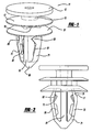
- Figure 1 is a prospective view showing the preferred embodiment of a trim retainer of the present invention
- Figure 2 is a side elevational view showing the preferred embodiment retainer disposed in a free condition
- Figure 3 is a side elevational view, taken 90 degrees to that of Figure 2, showing the preferred embodiment retainer;
- Figure 4 is an end elevational view, viewed from a tip, showing the preferred embodiment retainer, with the solid lines indicating its free condition and the dashed lines indicating its compressed insertion condition;
- Figure 5 is a cross sectional view, taken a long line 5-5 of Figure 3, showing the preferred embodiment retainer
- Figure 6 is a side elevational view, like that of Figure 2, showing the preferred embodiment retainer, with the solid lines indicating its free condition and the phantom lines indicating its compressed insertion condition;
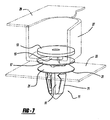
- Figure 7 is a perspective view showing the preferred embodiment retainer fastening an interior trim panel to an automotive vehicle body panel.
- a trim retainer or fastener 11 has a first circular head 13, a circular-cylindrical stem 15, a circular second head 17, a second stem 19 and a laterally enlarged umbrella 21.
- Second stem 19 has a circular-cylindrical central section bordered by four radially extending supports, each having a generally rectangular cross sectional shape.
- Umbrella 21 is somewhat flexible, has a tapered top surface 23, and has a somewhat concave and undercut bottom surface 25.
- a dog house 27 of an interior trim panel 29 is removable affixed to first stem 15 between first and second heads 13 and 17, respectively.
- a lower edge 31 of umbrella 21 seals against a face of a structural body panel 33 to deter transmission of moisture through a hole 35 and body panel 33.
- a post 51 centrally and coaxially extends from the bottom of umbrella 21.
- Post 51 has a typical cross sectional shape defined by opposite lateral edges 53, each having a slightly curved configuration, and slightly tapered and somewhat flat internal segments 55 connected to middle flat segments 57.
- a tapered tip 59 is located at a leading end of post 51 opposite umbrella 21.
- An arm 71 flexibly spans between a leading end of post 51 adjacent tip 59 and bottom surface 25 of umbrella 21. It is alternately envisioned that a trailing end of arm 71 is flexibly connected to the trailing end of post 51 although the performance may not be as desirable as with the preferred embodiment.
- post 51 is elongated in a longitudinal direction and arm 71 is also predominately elongated in the longitudinal direction but defined by a first lead in angled segment 73 and a reversed angled securing segment 75.
- arm 71 which are in mirrored symmetry to each other, and separated by post 51.
- An external notch 77 is located on each arm 71.
- An internally projecting rib 81 extends in a somewhat longitudinally elongated manner from an inside surface of each arm 71.
- Each rib 81 has a generally rectangular cross sectional shape of less lateral width than the adjacent segment of the arm.
- a pair of angular extension wings 83 of generally triangular shape, laterally and circumferentially project from lateral edges of each arm 71.
- the external notch 77 is located substantially between the rib 81 and the laterally enlarged member 21 and also between the angular extension wings 83.
- Retainer 11 is preferably injection molded from an impact modified acetal copolymer plastic material, however, it should be appreciated that other materials may alternately be employed.
- an automotive vehicle, interior trim panel such as an interior door trim panel
- Stem 15 is snapped in a sliding manner into a key-holed opening in dog house 27, as is shown in Figure 7.
- tip 59 of retainer 11 is aligned with hole 35 in sheet metal body panel 33 (for example, a structural door panel or quarter inner panel).
- Trim panel 29 is then manually pushed toward body panel 33 such that contact of an internal edge of hole 35 against leading segment 73 of each arm 71 caused inward flexure of each arm 71 towards post 51.
- rib 81 is moved from its free position to a compressed position 81' as can be seen in Figure 6.
- each rib 81' operably contacts against a generally parallel segment 57 (see Figure 5) of post 51 to deter over-compression and setting of each arm 71.
- Body panel 33 rides against leading edges of wings 83 there by being inwardly flexed to positions 83' (see Figure 4) relative to the adjacent arm segment passing through hole 35.
- Arms 71 and wings 83 return substantially to their free positions, but with slight compression, when retainer 11 is fully inserted into body panel 33, as shown in Figure 6.
- the slightly tapered segments 55 of post 51 allow for the inward flexure of wings 83 while the middle segments 57 operably abut against ribs 81 when arms 71 are fully compressed.
- trim retainer of the present invention can be used for securing other automotive vehicle components, such as and not be limited to, garnish moldings, package shelves, sail trim panels, headliners, lamps, trunk trim and the like.
- wing, rib, arm, post and other shapes may be provided, such as with additional radii and the like, although various advantages of the present invention may not be realized.
- present invention ribs may or may not be used in combination with the present invention wings, although various advantages of the present invention may not be realized.
- the post and tip may extend longitudinally beyond the leading intersection of the arms to provide an additional alignment and locating feature prior to full insertion, although again, all of the advantages of the present invention may not be provided. It is alternately envisioned that more or less heads and wings may be included, although various advantageous of the present invention may not be utilized. It is intended by the following claims to cover these and any other departures from the disclosed embodiments which fall within the true spirit of this invention.
Landscapes
- Engineering & Computer Science (AREA)
- General Engineering & Computer Science (AREA)
- Mechanical Engineering (AREA)
- Vehicle Interior And Exterior Ornaments, Soundproofing, And Insulation (AREA)
- Insertion Pins And Rivets (AREA)
Abstract
Description
- The present application relates generally to fasteners and more particularly to an automotive vehicle trim retainer.
- Conventional polymeric fasteners have been used in the automotive industry to retain interior trim panels to sheet metal structure. Examples of such traditional fasteners are disclosed in the following U.S. Patent Numbers;
5,592,719 entitled "Fastening Clip" which issued to Eto et al. on January 14, 1997;5,573,362 entitled "Fastener Including Elastic Legs for Retaining the Fastener in a Mounting Hole" which issued to Asami et al. on November 12, 1996; and5,301,396 entitled "Fastener Assembly with Compression Member" which issued to Benoit on April 12, 1994. Known fasteners such as these have unsuccessfully attempted to provide desirable insertion versus extraction forces while also achieving self-centering and over-compression resistance. Moreover, many conventional polymeric fasteners are not acceptably reusable after removal from the often sharp, sheet metal hole edges. - In accordance with the present invention, a retainer employs a flexible arm with an internal rib. In another aspect of the present invention, a retainer has at least one generally triangularly shaped projection laterally extending from an arm. A further aspect of the present invention retainer provides a laterally enlarged member, a trim panel-retaining head and stem, a central post, one or more flexible wings flexibly spanning between a tip of the post and the laterally enlarged member, and an internal rib and/or at least a pair of generally angular extensions flexibly extending from each arm.
- The retainer of the present invention is advantageous over conventional fasteners in that the ribs of the present invention deter the arm from taking an undesired "set" by not allowing each arm to become overcompressed or collapse more than is desired to clear the sheet metal hole into which the retainer is designed for. Furthermore, the generally triangular projections or angular extensions assist in achieving somewhat higher and more consistent extraction forces over a greater range of reusability as compared to prior door trim retainers. Additional advantages and features of the present invention will become apparent from the following description and appended claims, taken in conjunction with the accompanying drawings.
- Figure 1 is a prospective view showing the preferred embodiment of a trim retainer of the present invention;
- Figure 2 is a side elevational view showing the preferred embodiment retainer disposed in a free condition;
- Figure 3 is a side elevational view, taken 90 degrees to that of Figure 2, showing the preferred embodiment retainer;
- Figure 4 is an end elevational view, viewed from a tip, showing the preferred embodiment retainer, with the solid lines indicating its free condition and the dashed lines indicating its compressed insertion condition;
- Figure 5 is a cross sectional view, taken a long line 5-5 of Figure 3, showing the preferred embodiment retainer;
- Figure 6 is a side elevational view, like that of Figure 2, showing the preferred embodiment retainer, with the solid lines indicating its free condition and the phantom lines indicating its compressed insertion condition; and
- Figure 7 is a perspective view showing the preferred embodiment retainer fastening an interior trim panel to an automotive vehicle body panel.
- Referring to Figure 1 - 3, 5 and 7, a trim retainer or
fastener 11 has a firstcircular head 13, a circular-cylindrical stem 15, a circularsecond head 17, asecond stem 19 and a laterally enlargedumbrella 21.Second stem 19 has a circular-cylindrical central section bordered by four radially extending supports, each having a generally rectangular cross sectional shape. Umbrella 21 is somewhat flexible, has a tapered top surface 23, and has a somewhat concave andundercut bottom surface 25. Adog house 27 of aninterior trim panel 29 is removable affixed tofirst stem 15 between first andsecond heads lower edge 31 ofumbrella 21 seals against a face of astructural body panel 33 to deter transmission of moisture through ahole 35 andbody panel 33. - A
post 51 centrally and coaxially extends from the bottom ofumbrella 21.Post 51 has a typical cross sectional shape defined by oppositelateral edges 53, each having a slightly curved configuration, and slightly tapered and somewhat flatinternal segments 55 connected to middleflat segments 57. Atapered tip 59 is located at a leading end ofpost 51opposite umbrella 21. Anarm 71 flexibly spans between a leading end ofpost 51adjacent tip 59 andbottom surface 25 ofumbrella 21. It is alternately envisioned that a trailing end ofarm 71 is flexibly connected to the trailing end ofpost 51 although the performance may not be as desirable as with the preferred embodiment. Returning to the preferred embodiment,post 51 is elongated in a longitudinal direction andarm 71 is also predominately elongated in the longitudinal direction but defined by a first lead inangled segment 73 and a reversedangled securing segment 75. There are twoarms 71 which are in mirrored symmetry to each other, and separated bypost 51. An external notch 77 is located on eacharm 71. - An internally projecting
rib 81 extends in a somewhat longitudinally elongated manner from an inside surface of eacharm 71. Eachrib 81 has a generally rectangular cross sectional shape of less lateral width than the adjacent segment of the arm. Furthermore, a pair ofangular extension wings 83, of generally triangular shape, laterally and circumferentially project from lateral edges of eacharm 71. The external notch 77 is located substantially between therib 81 and the laterally enlargedmember 21 and also between theangular extension wings 83.Retainer 11 is preferably injection molded from an impact modified acetal copolymer plastic material, however, it should be appreciated that other materials may alternately be employed. - During use, an automotive vehicle, interior trim panel, such as an interior door trim panel, is secured to the heads and stem of
retainer 11.Stem 15 is snapped in a sliding manner into a key-holed opening indog house 27, as is shown in Figure 7. Thereafter,tip 59 ofretainer 11 is aligned withhole 35 in sheet metal body panel 33 (for example, a structural door panel or quarter inner panel). This can best be observed in Figures 4, 6 and 7.Trim panel 29 is then manually pushed towardbody panel 33 such that contact of an internal edge ofhole 35 against leadingsegment 73 of eacharm 71 caused inward flexure of eacharm 71 towardspost 51. Thus,rib 81 is moved from its free position to a compressed position 81' as can be seen in Figure 6. An internal edge of each rib 81' operably contacts against a generally parallel segment 57 (see Figure 5) ofpost 51 to deter over-compression and setting of eacharm 71.Body panel 33 rides against leading edges ofwings 83 there by being inwardly flexed to positions 83' (see Figure 4) relative to the adjacent arm segment passing throughhole 35.Arms 71 andwings 83 return substantially to their free positions, but with slight compression, whenretainer 11 is fully inserted intobody panel 33, as shown in Figure 6. It is noteworthy that the slightlytapered segments 55 ofpost 51 allow for the inward flexure ofwings 83 while themiddle segments 57 operably abut againstribs 81 whenarms 71 are fully compressed. Thus, significantly improved extraction force consistency, improved reusability performance, insertion self-centering and minimization of arm setting are possible with the present invention. - While certain aspects of the trim retainer have been disclosed, it should be appreciated that other variations maybe employed. For example, a trim retainer of the present invention can be used for securing other automotive vehicle components, such as and not be limited to, garnish moldings, package shelves, sail trim panels, headliners, lamps, trunk trim and the like. Moreover, slightly different wing, rib, arm, post and other shapes may be provided, such as with additional radii and the like, although various advantages of the present invention may not be realized. It should also be appreciated that the present invention ribs may or may not be used in combination with the present invention wings, although various advantages of the present invention may not be realized. Additionally, the post and tip may extend longitudinally beyond the leading intersection of the arms to provide an additional alignment and locating feature prior to full insertion, although again, all of the advantages of the present invention may not be provided. It is alternately envisioned that more or less heads and wings may be included, although various advantageous of the present invention may not be utilized. It is intended by the following claims to cover these and any other departures from the disclosed embodiments which fall within the true spirit of this invention.
Claims (19)
- A retainer apparatus comprising;(a) a central post (51) elongated in a longitudinal direction;(b) a laterally enlarged member (21) affixed to a trailing end of the post (51);(c) a least one elongated arm (71) having a first end flexibly coupled to the post (51); and(d) a rib (81) internally extending from the arm (71), the rib being spaced away from the post (51) when in its free position and being moved to an inward position immediately adjacent the post (51) during arm insertion.
- A retainer apparatus comprising;(a) a central post (51) elongated in a longitudinal direction;(b) a laterally enlarged member (21) affixed to a trailing end of the post (51);(c) a least one elongated arm (71) flexibly coupled to the post (51); and(d) at least a pair of angular extensions (83) each projecting from an opposite lateral side edge of the arm (71).
- The retainer apparatus of anyone of Claims 1 and 2 further comprising a stem (19) and a head (17) coupled to the laterally enlarged member (21) by the stem (19), and the laterally enlarged member (21) having a substantially concave shape adjacent the post (51).
- The retainer apparatus of Claim 3 further comprising a second stem (15) and a second head (13) coupled to the first head (17) by the second stem (15), the heads (13, 17) and the laterally enlarged member (21) being substantially coaxial, the stems (15, 19) and the post (51) being substantially coaxial.
- The retainer apparatus of anyone of Claims 1 and 2 further comprising a stem and head coupled to the post, and an automotive interior trim panel attached to the stem and head.
- The retainer apparatus of anyone of the preceding Claims wherein a second end (75) of the arm (71) is flexibly connected to the laterally enlarged member (21).
- The retainer apparatus of anyone of the preceding Claims further comprising a structural panel-engaging notch (77) located on an external surface of the arm (71).
- The retainer apparatus of anyone of the preceding Claims further comprising a second arm (71) flexibly coupled to the post (51), a rib (81) internally projecting from the second arm (71), only the two arms (71) flexibly extending from the post (51).
- The retainer apparatus of anyone of the preceding Claims wherein the post (51) has a substantially flat surface segment (57) facing the arm (71).
- The retainer apparatus of Claim 1 further comprising two substantially triangular extensions (83) laterally projecting from opposite side edges of the arm (71).
- The retainer apparatus of anyone of the preceding Claims wherein the laterally extending member (21), post (51) and arm (71) are all a single polymeric material piece.
- The retainer apparatus of Claim 1 wherein the rib (81) is elongated in the elongated direction of the arm (71) and has a lateral cross section smaller than that of the adjacent segment of the arm (71).
- The retainer apparatus of Claim 2 wherein each of the angular extensions (83) is substantially triangularly shaped.
- The retainer apparatus of Claim 2 further comprising a rib (81) projecting from an internal surface of the arm (71).
- The retainer apparatus of anyone of Claims 2, 10 and 13 wherein the angular extensions (83) are flexible relative to the adjacent portion of the arm (71) when inserted.
- The retainer apparatus of Claim 3 further comprising an automotive vehicle interior trim panel (29), the trim panel being coupled to at least one of the head (17) and stem (19).
- A method of using a fastener with an automotive vehicle trim panel (29) and a structural body panel (33), the method comprising;(a) attaching the fastener (11) to the automotive vehicle trim panel;(b) inserting a tapered tip of the fastener (11) into a hole of the body panel (33);(c) flexing at least a pair of arms (71) extending from the tip (59) inwardly toward each other during step (b);(d) deterring compression of the arms (71) at least in part by an internal rib (81) extending from each of the arms (71); and(e) inwardly flexing projections (83) triangularly extending adjacent opposite lateral edges of each arm (71), relative to each arm (71), during step (b).
- The method of Claim 17 further comprising making the retainer as a single piece from polymeric material.
- The method of Claim 17 wherein the ribs (81) abut against a central post (51), and each rib (81) is elongated in an elongated direction of each corresponding arm (71).
Applications Claiming Priority (1)
| Application Number | Priority Date | Filing Date | Title |
|---|---|---|---|
| US11/371,340 US7481474B2 (en) | 2006-03-08 | 2006-03-08 | Trim retainer |
Publications (3)
| Publication Number | Publication Date |
|---|---|
| EP1832760A2 true EP1832760A2 (en) | 2007-09-12 |
| EP1832760A3 EP1832760A3 (en) | 2007-12-19 |
| EP1832760B1 EP1832760B1 (en) | 2012-10-31 |
Family
ID=38069186
Family Applications (1)
| Application Number | Title | Priority Date | Filing Date |
|---|---|---|---|
| EP07103647A Active EP1832760B1 (en) | 2006-03-08 | 2007-03-06 | Trim Retainer |
Country Status (3)
| Country | Link |
|---|---|
| US (2) | US7481474B2 (en) |
| EP (1) | EP1832760B1 (en) |
| JP (1) | JP2007239991A (en) |
Cited By (2)
| Publication number | Priority date | Publication date | Assignee | Title |
|---|---|---|---|---|
| EP2048377A3 (en) * | 2007-10-04 | 2011-02-16 | A. Raymond et Cie. | Device for securing a construction element to a carrier section |
| DE102010033495A1 (en) | 2010-08-05 | 2011-10-06 | Audi Ag | Fastening device for releasable fastening of cover part at structural element of car body, has dome for forming releasable clip connection into opening of structural component, and holding socket integrally formed with cover part |
Families Citing this family (55)
| Publication number | Priority date | Publication date | Assignee | Title |
|---|---|---|---|---|
| SE524074C2 (en) * | 2000-06-02 | 2004-06-22 | Forsheda Ab | Apparatus for damping vibration of a vibrating surface and methods for mounting such a device |
| US20070063539A1 (en) * | 2005-09-12 | 2007-03-22 | Dimario Joseph | Snap-in mounting clip, panel having a snap-in mounting clip, and method of mounting the panel |
| US7481474B2 (en) * | 2006-03-08 | 2009-01-27 | Newfrey Llc | Trim retainer |
| US7614836B2 (en) * | 2006-05-09 | 2009-11-10 | Gm Global Technology Operations, Inc. | Arrangements for attaching components to surfaces |
| US20080052878A1 (en) | 2006-08-31 | 2008-03-06 | Lewis Jeffrey C | Fastener Clip with Seal |
| FR2916181B1 (en) * | 2007-05-14 | 2009-11-20 | Renault Sas | CLUTCH ELEMENT FOR A MOTOR VEHICLE SHIELD |
| US7927050B2 (en) * | 2007-05-30 | 2011-04-19 | Piolax Inc. | Interior part mounting clip |
| EP2006134B1 (en) * | 2007-06-21 | 2011-03-23 | Ford Global Technologies, LLC | Vehicle door |
| DE202007011105U1 (en) * | 2007-08-09 | 2007-10-18 | Itw Automotive Products Gmbh & Co. Kg | One-piece plastic clip |
| US7748089B2 (en) * | 2008-01-15 | 2010-07-06 | Illinois Tool Works Inc. | Auger clip assembly |
| JP4790751B2 (en) * | 2008-01-30 | 2011-10-12 | 株式会社パイオラックス | clip |
| JP5172758B2 (en) * | 2008-05-07 | 2013-03-27 | 株式会社ニフコ | Fastener |
| FR2938025B1 (en) * | 2008-11-04 | 2013-05-24 | Trw Automotive Electron & Comp | CLAMP FOR ATTACHING EQUIPMENT TO A STRUCTURE |
| DE112010002428T5 (en) * | 2009-06-12 | 2012-08-23 | Piolax Inc. | Mounting structure for a clip on a mountable member |
| DE102009032595A1 (en) | 2009-07-10 | 2011-01-13 | GM Global Technology Operations, Inc., Detroit | Side part for motor vehicle, has attachment device attaching internal wheel housing, where attachment device includes two connecting pieces that include guide for internal wheel housing in relation to side plate in vertical direction |
| CN102052372A (en) * | 2009-11-09 | 2011-05-11 | 鸿富锦精密工业(深圳)有限公司 | Fan fixer |
| US8834087B2 (en) * | 2010-10-29 | 2014-09-16 | Illinois Tool Works Inc. | Fastener clip assembly |
| JP5738004B2 (en) * | 2011-03-01 | 2015-06-17 | マツダ株式会社 | Interposition member holding structure, interposition member, and rattling prevention member |
| US8561265B2 (en) | 2011-04-12 | 2013-10-22 | Newfrey Llc | Interior trim fastener |
| EP2714375A1 (en) | 2011-06-02 | 2014-04-09 | A. Raymond et Cie | Fasteners manufactured by three-dimensional printing |
| USD704538S1 (en) * | 2011-12-26 | 2014-05-13 | Nifco Inc. | Fastener |
| USD704539S1 (en) * | 2011-12-26 | 2014-05-13 | Nifco Inc. | Fastener |
| DE102012007971A1 (en) * | 2012-04-20 | 2013-10-24 | Gm Global Technology Operations, Llc | Holding clip for fastening first component e.g. cover on second component e.g. interior panel outer structure, has retaining portions designed as parabolic cross sections, and joined to portions proximal and distal to locking portion |
| WO2013177108A1 (en) * | 2012-05-21 | 2013-11-28 | Illinois Tool Works Inc. | Snap-in fastener with sealing flange |
| US8622680B1 (en) * | 2012-06-28 | 2014-01-07 | Newfrey Llc | Grommet |
| JP6067277B2 (en) * | 2012-08-10 | 2017-01-25 | 大和化成工業株式会社 | Waterproof structure for vehicle doors |
| US9982694B2 (en) | 2012-12-19 | 2018-05-29 | Illinois Tool Works Inc. | Push through retainer connection with integrated hinging seal |
| FR3001008B1 (en) * | 2013-01-17 | 2016-05-27 | Trw Automotive Elect & Components Gmbh | FASTENING CLIP |
| JP6054192B2 (en) * | 2013-01-31 | 2016-12-27 | 大和化成工業株式会社 | Clip mounting structure |
| DE202013005158U1 (en) * | 2013-06-07 | 2014-09-08 | Dieter Ramsauer | Fastening device for mounting a retaining clip and other fittings in a perforated thin wall |
| JP6285681B2 (en) * | 2013-10-01 | 2018-02-28 | 株式会社パイオラックス | Locking tool to mounting hole |
| DE102014221927A1 (en) * | 2014-10-28 | 2016-04-28 | Ford Global Technologies, Llc | Clip for attaching panels to a vehicle body |
| JP1534862S (en) * | 2014-12-25 | 2015-10-13 | ||
| DE102015106223B4 (en) * | 2015-04-22 | 2024-09-12 | Illinois Tool Works Inc. | System for attaching a door module to an automobile door |
| US9802552B2 (en) | 2015-06-16 | 2017-10-31 | Ford Global Technologies, Pllc | Trim panel mounting system for securing a trim panel to a substrate |
| US9656585B2 (en) | 2015-08-25 | 2017-05-23 | Toyota Motor Engineering & Manufacturing North America, Inc. | Tether with J-shaped hook |
| US10328870B2 (en) | 2016-07-25 | 2019-06-25 | Deere & Company | Work vehicle upholstery mounting system |
| CN106594029A (en) * | 2016-12-30 | 2017-04-26 | 上汽通用五菱汽车股份有限公司 | Buckle structure capable of being firmly installed and improving sealability |
| WO2018170307A1 (en) * | 2017-03-15 | 2018-09-20 | Simpson Strong-Tie Company, Inc. | Composite sea wall system |
| JP6851884B2 (en) * | 2017-04-06 | 2021-03-31 | ポップリベット・ファスナー株式会社 | clip |
| US11800863B2 (en) * | 2017-05-10 | 2023-10-31 | Vm Products, Inc. | Rodent trap with presence indicator mechanism |
| USD931718S1 (en) * | 2017-06-07 | 2021-09-28 | Illinois Tool Works Inc. | Retainer |
| CN207927103U (en) * | 2018-03-30 | 2018-09-28 | 京东方科技集团股份有限公司 | Connector, display device and vehicle |
| CN111075805A (en) * | 2018-10-18 | 2020-04-28 | 伊利诺斯工具制品有限公司 | Fastening clip |
| US11078941B2 (en) * | 2019-01-15 | 2021-08-03 | Black & Decker Inc. | Cast-in place anchor assembly |
| ES2950241T3 (en) * | 2020-02-10 | 2023-10-06 | Zanini Auto Grup Sa | Vehicle wheel insert |
| US11815124B2 (en) * | 2021-03-05 | 2023-11-14 | Illinois Tool Works Inc. | Fastener assembly |
| US20220341453A1 (en) * | 2021-04-26 | 2022-10-27 | Illinois Tool Works Inc. | Fastener with Integral Seal |
| USD994445S1 (en) * | 2021-06-30 | 2023-08-08 | Reynolds Presto Products Inc. | Connector for expanded cell confinement web with curved handle |
| USD1000262S1 (en) * | 2021-06-30 | 2023-10-03 | Reynolds Presto Products Inc. | Connector device for expanded cell confinement web |
| USD1000263S1 (en) * | 2021-06-30 | 2023-10-03 | Reynolds Presto Products Inc. | Connector for expanded cell confinement web with polygon handle |
| WO2023129172A1 (en) * | 2021-12-27 | 2023-07-06 | Google Llc | Thermally insulating and electrically conductive spacer |
| US11728636B2 (en) * | 2021-12-31 | 2023-08-15 | Lear Corporation | Flat flexible electrical conductor and supporting device therefor |
| US11904667B2 (en) * | 2022-03-24 | 2024-02-20 | Nissan North America, Inc. | Vehicle door assembly |
| US12523245B1 (en) * | 2022-06-06 | 2026-01-13 | William Ryan Grepper | Panel fastening system |
Citations (3)
| Publication number | Priority date | Publication date | Assignee | Title |
|---|---|---|---|---|
| US5301396A (en) | 1993-01-13 | 1994-04-12 | Illinois Tool Works Inc. | Fastener assembly with compression member |
| US5573362A (en) | 1994-08-16 | 1996-11-12 | Nifco Inc. | Fastener including elastic legs for retaining the fastener in a mounting hole |
| US5592719A (en) | 1994-03-10 | 1997-01-14 | Nifco Inc. | Fastening clip |
Family Cites Families (71)
| Publication number | Priority date | Publication date | Assignee | Title |
|---|---|---|---|---|
| US3093874A (en) * | 1960-12-19 | 1963-06-18 | Illinois Tool Works | Fastener |
| GB807726A (en) | 1956-02-09 | 1959-01-21 | Carr Fastener Co Ltd | Improvements in and relating to a fastening device for securing an article to an apertured support |
| US3029486A (en) * | 1957-10-04 | 1962-04-17 | Raymond A | Plastic panel clip |
| DE2250729C2 (en) | 1972-10-16 | 1974-10-10 | Fa. A. Raymond, 7850 Loerrach | Bracket |
| US3905270A (en) * | 1973-07-11 | 1975-09-16 | Illinois Tool Works | One-piece fastening element |
| JPS50113660A (en) * | 1974-02-14 | 1975-09-05 | ||
| US4393551A (en) * | 1980-08-25 | 1983-07-19 | Phillips Plastics Corp. | Rotatably engaging head for fastener |
| DE8024678U1 (en) * | 1980-09-15 | 1980-12-18 | Fa. A. Raymond, 7850 Loerrach | Fixing device for cladding panels |
| JPS6017527Y2 (en) * | 1980-09-22 | 1985-05-29 | 株式会社ニフコ | plastic fasteners |
| USD268006S (en) | 1980-10-27 | 1983-02-22 | Phillips Plastics Corporation | Drive fastener |
| US4472918A (en) * | 1981-05-11 | 1984-09-25 | Allen Industries, Inc. | Concealed fastener receiver |
| US4422276A (en) * | 1981-08-10 | 1983-12-27 | General Motors Corporation | Door trim fastener assembly |
| JPS58130108U (en) * | 1982-02-26 | 1983-09-02 | 河西工業株式会社 | Component attachment device |
| JPS5911910U (en) | 1982-07-14 | 1984-01-25 | 北川工業株式会社 | Fixture |
| US4489465A (en) * | 1983-05-27 | 1984-12-25 | Jack Lemkin | Security fastener |
| JPS60196013U (en) * | 1984-06-04 | 1985-12-27 | 株式会社 ニフコ | plastic anchor clip |
| JPH0676804B2 (en) * | 1985-07-15 | 1994-09-28 | 株式会社ニフコ | Fasteners for fastening two panels in a face-to-face manner |
| JPH0619170B2 (en) * | 1986-01-22 | 1994-03-16 | 株式会社ニフコ | Board fastening |
| JPH06105087B2 (en) * | 1986-09-30 | 1994-12-21 | 株式会社ニフコ | Board fastening |
| US5165833A (en) * | 1987-09-24 | 1992-11-24 | Nifco Inc. | Clip |
| US4861208A (en) * | 1989-01-30 | 1989-08-29 | Chrysler Motors Corporation | Door trim panel fastening assembly |
| US4938645A (en) * | 1989-05-30 | 1990-07-03 | Phillips Plastics Corporation | Tee tree fastener |
| US5039267A (en) * | 1989-05-30 | 1991-08-13 | Phillips Plastics Corporation | Tee tree fastener |
| JP2860341B2 (en) * | 1989-09-25 | 1999-02-24 | 株式会社パイオラックス | Retaining clip |
| DE8911881U1 (en) * | 1989-10-05 | 1989-11-23 | TRW United-Carr GmbH & Co KG, 6753 Enkenbach-Alsenborn | Plastic retaining element |
| US5011356A (en) * | 1990-01-25 | 1991-04-30 | Itw-Mapri Industria E Comercio Ltda | Panel fastener |
| DE4014589C1 (en) | 1990-05-07 | 1991-08-08 | Trw United-Carr Gmbh & Co Kg, 6753 Enkenbach-Alsenborn, De | |
| JP2829132B2 (en) * | 1990-12-21 | 1998-11-25 | 北川工業株式会社 | Fixture |
| FR2673249B1 (en) * | 1991-02-22 | 1993-07-02 | Itw De France | FASTENING CLIP. |
| US5152582A (en) * | 1991-03-28 | 1992-10-06 | American Seating Company | Self-aligning fastener system having stud-engaging resilient legs |
| DE4117114C1 (en) * | 1991-05-25 | 1992-08-06 | A. Raymond Kg, 7850 Loerrach, De | |
| JP3450342B2 (en) * | 1991-12-16 | 2003-09-22 | 株式会社ニフコ | Stop |
| JP2585443Y2 (en) * | 1992-03-30 | 1998-11-18 | 鬼怒川ゴム工業株式会社 | Fastener |
| EP0589773B1 (en) * | 1992-09-21 | 1997-06-04 | Canadian Plastics Inc. | Cosmetic package |
| US5316423A (en) * | 1992-12-11 | 1994-05-31 | Kin Daniel C C | Acoustic isolation fastener and method for attachment |
| USD355113S (en) | 1992-12-15 | 1995-02-07 | Nifco Inc. | Board clamp |
| USD354219S (en) | 1992-12-15 | 1995-01-10 | Nifco Inc. | Board clamp |
| JPH071318U (en) * | 1993-06-04 | 1995-01-10 | ポップリベット・ファスナー株式会社 | Fasteners that can be installed from one direction |
| US5393185A (en) * | 1993-10-01 | 1995-02-28 | Illinois Tool Works Inc. | Push-in fastener having fins with work-piece engagement ribs |
| DE9411165U1 (en) * | 1994-07-09 | 1994-09-08 | Panduit GmbH, 61352 Bad Homburg | Expansion anchor |
| US5507610A (en) * | 1994-07-27 | 1996-04-16 | Emhart Inc. | Refusable fastener including a pin and grommet |
| JP3312230B2 (en) * | 1994-07-29 | 2002-08-05 | 株式会社パイオラックス | Component mounting structure |
| JPH0861336A (en) * | 1994-08-19 | 1996-03-08 | Togo Seisakusho:Kk | clip |
| US5468108A (en) * | 1994-09-12 | 1995-11-21 | Illinois Tool Works Inc. | Spiral flex tree fastener |
| US5507310A (en) * | 1994-09-13 | 1996-04-16 | Watts Investment Company | System of plumbing for recreational vehicles |
| DE19504692A1 (en) * | 1995-02-13 | 1996-08-14 | United Carr Gmbh Trw | Connection between a support and a plate element |
| US5586853A (en) | 1995-03-16 | 1996-12-24 | Davidson Textron Inc. | Fastener cage for a panel |
| JP3635121B2 (en) * | 1995-03-30 | 2005-04-06 | 株式会社パイオラックス | Fastener |
| JP3466347B2 (en) * | 1995-11-27 | 2003-11-10 | 株式会社ニフコ | Clip for fixing elastic members |
| USD390776S (en) | 1995-12-08 | 1998-02-17 | Nifco Inc. | Attachment for a plate member |
| JP3750695B2 (en) * | 1996-01-08 | 2006-03-01 | 株式会社ニフコ | Plate connector |
| US5851097A (en) * | 1997-06-03 | 1998-12-22 | Illinois Tool Works Inc. | Article with tethered prong fastener |
| US5775859A (en) * | 1997-06-06 | 1998-07-07 | National Molding Corp. | Mat fastener |
| DE29718487U1 (en) * | 1997-10-17 | 1997-12-18 | Trw United-Carr Gmbh & Co Kg, 67677 Enkenbach-Alsenborn | Connection between a carrier, in particular a body part of a motor vehicle, and a plate element |
| DE19753678A1 (en) * | 1997-12-03 | 1999-06-10 | United Carr Gmbh Trw | Connection between a carrier, in particular a body part of a motor vehicle, and a plate element, in particular a door trim |
| DE19806827A1 (en) * | 1998-02-18 | 1999-08-19 | Trw Automotive Electron & Comp | Connection between a support and a plate element |
| DE29810437U1 (en) * | 1998-06-10 | 1998-10-01 | TRW Automotive Electronics & Components GmbH & Co. KG, 78315 Radolfzell | Connecting element between a carrier, in particular a body part of a motor vehicle and a plate element |
| DE19830752C2 (en) * | 1998-07-09 | 2003-10-16 | Itw Ateco Gmbh | mounting clip |
| US5975820A (en) * | 1998-11-03 | 1999-11-02 | Illinois Tool Works Inc. | Two-piece pin and grommet |
| FR2789454B1 (en) * | 1999-02-09 | 2001-04-27 | Itw De France | FASTENER EQUIPPED WITH A SNAP FOOT TO PRESS THROUGH A HOLE IN A PANEL |
| GB2360322B8 (en) | 2000-03-15 | 2016-05-25 | Trw Automotive Systems Ltd | Improvements relating to fasteners |
| JP2002081422A (en) * | 2000-09-07 | 2002-03-22 | Nifco Inc | Connector for two members |
| US6572317B2 (en) * | 2000-09-14 | 2003-06-03 | Piolax Inc. | Resilient fastener clip |
| USD456699S1 (en) * | 2001-04-27 | 2002-05-07 | Emhart Llc | Clip for fastening a mounting member to an automobile |
| US6449814B1 (en) * | 2001-09-13 | 2002-09-17 | Summit Polymers, Inc. | Trim fastener clip employing multiple lines-of-contact stabilization |
| DE10218952A1 (en) | 2002-04-27 | 2003-11-06 | Raymond A & Cie | fastener |
| US7114221B2 (en) * | 2003-01-17 | 2006-10-03 | Newfrey Llc | Two-piece interior trim retainer |
| US6910840B2 (en) * | 2003-06-06 | 2005-06-28 | National Molding Corp. | Fastener |
| US20050079033A1 (en) * | 2003-10-09 | 2005-04-14 | Benedetti Steven Michael | Arcuate-hinge fastener |
| US6974292B2 (en) * | 2003-10-30 | 2005-12-13 | Illinois Tool Works Inc | One-piece reusable plastic fastener |
| US7481474B2 (en) * | 2006-03-08 | 2009-01-27 | Newfrey Llc | Trim retainer |
-
2006
- 2006-03-08 US US11/371,340 patent/US7481474B2/en not_active Expired - Lifetime
-
2007
- 2007-02-09 JP JP2007029965A patent/JP2007239991A/en active Pending
- 2007-03-06 EP EP07103647A patent/EP1832760B1/en active Active
-
2008
- 2008-12-12 US US12/333,706 patent/US7770266B2/en not_active Expired - Lifetime
Patent Citations (3)
| Publication number | Priority date | Publication date | Assignee | Title |
|---|---|---|---|---|
| US5301396A (en) | 1993-01-13 | 1994-04-12 | Illinois Tool Works Inc. | Fastener assembly with compression member |
| US5592719A (en) | 1994-03-10 | 1997-01-14 | Nifco Inc. | Fastening clip |
| US5573362A (en) | 1994-08-16 | 1996-11-12 | Nifco Inc. | Fastener including elastic legs for retaining the fastener in a mounting hole |
Cited By (2)
| Publication number | Priority date | Publication date | Assignee | Title |
|---|---|---|---|---|
| EP2048377A3 (en) * | 2007-10-04 | 2011-02-16 | A. Raymond et Cie. | Device for securing a construction element to a carrier section |
| DE102010033495A1 (en) | 2010-08-05 | 2011-10-06 | Audi Ag | Fastening device for releasable fastening of cover part at structural element of car body, has dome for forming releasable clip connection into opening of structural component, and holding socket integrally formed with cover part |
Also Published As
| Publication number | Publication date |
|---|---|
| EP1832760B1 (en) | 2012-10-31 |
| EP1832760A3 (en) | 2007-12-19 |
| JP2007239991A (en) | 2007-09-20 |
| US7770266B2 (en) | 2010-08-10 |
| US20070210602A1 (en) | 2007-09-13 |
| US20090089982A1 (en) | 2009-04-09 |
| US7481474B2 (en) | 2009-01-27 |
Similar Documents
| Publication | Publication Date | Title |
|---|---|---|
| EP1832760B1 (en) | Trim Retainer | |
| US20090191025A1 (en) | Fastener | |
| US20040135394A1 (en) | Vehicular door trim having a molded-in substrate fastener | |
| US6874983B2 (en) | Ergonomic fastener | |
| US4759670A (en) | Multi-purpose two-piece plastic fastener | |
| EP1248911B1 (en) | Quick access rubber panel fastener | |
| US9630572B2 (en) | Clip | |
| US5286152A (en) | Rivet fastener with push-in releasable drive pin | |
| US4626620A (en) | Wire bundle and grommet assembly | |
| US6406236B1 (en) | Panel fastener and method of manufacture thereof | |
| US20050217082A1 (en) | Ergonomic fastener | |
| US6669426B1 (en) | Tree fastener | |
| EP3491258B1 (en) | Fastening clip | |
| US5718025A (en) | Fixing device | |
| US20050079009A1 (en) | Fastener for fixed rib applications | |
| US20180291942A1 (en) | Clip | |
| US20130199004A1 (en) | Fastener clip assembly | |
| US6553615B1 (en) | Two-piece sliding grommet | |
| US20030159255A1 (en) | Clamp retention device | |
| EP2267321A1 (en) | Trim panel retainer assembly | |
| CA2144030A1 (en) | Retention clip | |
| EP1696141A1 (en) | Tethered retainer assembly | |
| EP2604870B1 (en) | An integrated clip | |
| JP2004535533A (en) | Self-tapping fastener and method for installing weather seal | |
| US20070116537A1 (en) | Push-back fastener |
Legal Events
| Date | Code | Title | Description |
|---|---|---|---|
| PUAI | Public reference made under article 153(3) epc to a published international application that has entered the european phase |
Free format text: ORIGINAL CODE: 0009012 |
|
| AK | Designated contracting states |
Kind code of ref document: A2 Designated state(s): AT BE BG CH CY CZ DE DK EE ES FI FR GB GR HU IE IS IT LI LT LU LV MC MT NL PL PT RO SE SI SK TR |
|
| AX | Request for extension of the european patent |
Extension state: AL BA HR MK YU |
|
| PUAL | Search report despatched |
Free format text: ORIGINAL CODE: 0009013 |
|
| AK | Designated contracting states |
Kind code of ref document: A3 Designated state(s): AT BE BG CH CY CZ DE DK EE ES FI FR GB GR HU IE IS IT LI LT LU LV MC MT NL PL PT RO SE SI SK TR |
|
| AX | Request for extension of the european patent |
Extension state: AL BA HR MK YU |
|
| 17P | Request for examination filed |
Effective date: 20080610 |
|
| 17Q | First examination report despatched |
Effective date: 20080722 |
|
| AKX | Designation fees paid |
Designated state(s): DE FR IT |
|
| GRAP | Despatch of communication of intention to grant a patent |
Free format text: ORIGINAL CODE: EPIDOSNIGR1 |
|
| GRAS | Grant fee paid |
Free format text: ORIGINAL CODE: EPIDOSNIGR3 |
|
| GRAA | (expected) grant |
Free format text: ORIGINAL CODE: 0009210 |
|
| AK | Designated contracting states |
Kind code of ref document: B1 Designated state(s): DE FR IT |
|
| REG | Reference to a national code |
Ref country code: DE Ref legal event code: R096 Ref document number: 602007026360 Country of ref document: DE Effective date: 20121227 |
|
| PLBE | No opposition filed within time limit |
Free format text: ORIGINAL CODE: 0009261 |
|
| STAA | Information on the status of an ep patent application or granted ep patent |
Free format text: STATUS: NO OPPOSITION FILED WITHIN TIME LIMIT |
|
| 26N | No opposition filed |
Effective date: 20130801 |
|
| REG | Reference to a national code |
Ref country code: DE Ref legal event code: R097 Ref document number: 602007026360 Country of ref document: DE Effective date: 20130801 |
|
| PGFP | Annual fee paid to national office [announced via postgrant information from national office to epo] |
Ref country code: IT Payment date: 20140320 Year of fee payment: 8 |
|
| PG25 | Lapsed in a contracting state [announced via postgrant information from national office to epo] |
Ref country code: IT Free format text: LAPSE BECAUSE OF NON-PAYMENT OF DUE FEES Effective date: 20150306 |
|
| REG | Reference to a national code |
Ref country code: FR Ref legal event code: PLFP Year of fee payment: 10 |
|
| REG | Reference to a national code |
Ref country code: FR Ref legal event code: PLFP Year of fee payment: 11 |
|
| REG | Reference to a national code |
Ref country code: FR Ref legal event code: PLFP Year of fee payment: 12 |
|
| P01 | Opt-out of the competence of the unified patent court (upc) registered |
Effective date: 20230912 |
|
| PGFP | Annual fee paid to national office [announced via postgrant information from national office to epo] |
Ref country code: DE Payment date: 20260320 Year of fee payment: 20 |
|
| PGFP | Annual fee paid to national office [announced via postgrant information from national office to epo] |
Ref country code: FR Payment date: 20260324 Year of fee payment: 20 |