EP1832743A1 - Methods and apparatus for controlling rotational speed of a rotor - Google Patents
Methods and apparatus for controlling rotational speed of a rotor Download PDFInfo
- Publication number
- EP1832743A1 EP1832743A1 EP07103533A EP07103533A EP1832743A1 EP 1832743 A1 EP1832743 A1 EP 1832743A1 EP 07103533 A EP07103533 A EP 07103533A EP 07103533 A EP07103533 A EP 07103533A EP 1832743 A1 EP1832743 A1 EP 1832743A1
- Authority
- EP
- European Patent Office
- Prior art keywords
- rotor
- pitch
- wind turbine
- angle
- torque
- Prior art date
- Legal status (The legal status is an assumption and is not a legal conclusion. Google has not performed a legal analysis and makes no representation as to the accuracy of the status listed.)
- Granted
Links
- 238000000034 method Methods 0.000 title abstract description 27
- 230000007704 transition Effects 0.000 claims description 9
- 230000008859 change Effects 0.000 claims description 8
- 230000001276 controlling effect Effects 0.000 description 28
- 238000005259 measurement Methods 0.000 description 7
- 238000012545 processing Methods 0.000 description 5
- 230000015654 memory Effects 0.000 description 4
- 230000008569 process Effects 0.000 description 4
- 230000001105 regulatory effect Effects 0.000 description 4
- 239000012530 fluid Substances 0.000 description 3
- 230000033001 locomotion Effects 0.000 description 3
- 230000003287 optical effect Effects 0.000 description 3
- 238000010586 diagram Methods 0.000 description 2
- 230000000694 effects Effects 0.000 description 2
- 238000012544 monitoring process Methods 0.000 description 2
- 230000003071 parasitic effect Effects 0.000 description 2
- 238000005086 pumping Methods 0.000 description 2
- 230000003068 static effect Effects 0.000 description 2
- 239000000126 substance Substances 0.000 description 2
- XLYOFNOQVPJJNP-UHFFFAOYSA-N water Substances O XLYOFNOQVPJJNP-UHFFFAOYSA-N 0.000 description 2
- 230000005355 Hall effect Effects 0.000 description 1
- 230000033228 biological regulation Effects 0.000 description 1
- 239000003990 capacitor Substances 0.000 description 1
- 238000004891 communication Methods 0.000 description 1
- 238000001816 cooling Methods 0.000 description 1
- 230000008878 coupling Effects 0.000 description 1
- 238000010168 coupling process Methods 0.000 description 1
- 238000005859 coupling reaction Methods 0.000 description 1
- 238000013461 design Methods 0.000 description 1
- 238000006073 displacement reaction Methods 0.000 description 1
- 239000004744 fabric Substances 0.000 description 1
- 230000006870 function Effects 0.000 description 1
- 238000009499 grossing Methods 0.000 description 1
- 230000006698 induction Effects 0.000 description 1
- 238000009434 installation Methods 0.000 description 1
- 230000003993 interaction Effects 0.000 description 1
- 238000012986 modification Methods 0.000 description 1
- 230000004048 modification Effects 0.000 description 1
- 230000010355 oscillation Effects 0.000 description 1
- 238000012546 transfer Methods 0.000 description 1
Images


Classifications
-
- F—MECHANICAL ENGINEERING; LIGHTING; HEATING; WEAPONS; BLASTING
- F03—MACHINES OR ENGINES FOR LIQUIDS; WIND, SPRING, OR WEIGHT MOTORS; PRODUCING MECHANICAL POWER OR A REACTIVE PROPULSIVE THRUST, NOT OTHERWISE PROVIDED FOR
- F03D—WIND MOTORS
- F03D7/00—Controlling wind motors
- F03D7/02—Controlling wind motors the wind motors having rotation axis substantially parallel to the air flow entering the rotor
- F03D7/0276—Controlling wind motors the wind motors having rotation axis substantially parallel to the air flow entering the rotor controlling rotor speed, e.g. variable speed
-
- F—MECHANICAL ENGINEERING; LIGHTING; HEATING; WEAPONS; BLASTING
- F03—MACHINES OR ENGINES FOR LIQUIDS; WIND, SPRING, OR WEIGHT MOTORS; PRODUCING MECHANICAL POWER OR A REACTIVE PROPULSIVE THRUST, NOT OTHERWISE PROVIDED FOR
- F03D—WIND MOTORS
- F03D7/00—Controlling wind motors
- F03D7/02—Controlling wind motors the wind motors having rotation axis substantially parallel to the air flow entering the rotor
- F03D7/022—Adjusting aerodynamic properties of the blades
- F03D7/0224—Adjusting blade pitch
-
- F—MECHANICAL ENGINEERING; LIGHTING; HEATING; WEAPONS; BLASTING
- F03—MACHINES OR ENGINES FOR LIQUIDS; WIND, SPRING, OR WEIGHT MOTORS; PRODUCING MECHANICAL POWER OR A REACTIVE PROPULSIVE THRUST, NOT OTHERWISE PROVIDED FOR
- F03D—WIND MOTORS
- F03D7/00—Controlling wind motors
- F03D7/02—Controlling wind motors the wind motors having rotation axis substantially parallel to the air flow entering the rotor
- F03D7/0272—Controlling wind motors the wind motors having rotation axis substantially parallel to the air flow entering the rotor by measures acting on the electrical generator
-
- F—MECHANICAL ENGINEERING; LIGHTING; HEATING; WEAPONS; BLASTING
- F03—MACHINES OR ENGINES FOR LIQUIDS; WIND, SPRING, OR WEIGHT MOTORS; PRODUCING MECHANICAL POWER OR A REACTIVE PROPULSIVE THRUST, NOT OTHERWISE PROVIDED FOR
- F03D—WIND MOTORS
- F03D7/00—Controlling wind motors
- F03D7/02—Controlling wind motors the wind motors having rotation axis substantially parallel to the air flow entering the rotor
- F03D7/04—Automatic control; Regulation
- F03D7/042—Automatic control; Regulation by means of an electrical or electronic controller
-
- F—MECHANICAL ENGINEERING; LIGHTING; HEATING; WEAPONS; BLASTING
- F03—MACHINES OR ENGINES FOR LIQUIDS; WIND, SPRING, OR WEIGHT MOTORS; PRODUCING MECHANICAL POWER OR A REACTIVE PROPULSIVE THRUST, NOT OTHERWISE PROVIDED FOR
- F03D—WIND MOTORS
- F03D7/00—Controlling wind motors
- F03D7/06—Controlling wind motors the wind motors having rotation axis substantially perpendicular to the air flow entering the rotor
-
- F—MECHANICAL ENGINEERING; LIGHTING; HEATING; WEAPONS; BLASTING
- F05—INDEXING SCHEMES RELATING TO ENGINES OR PUMPS IN VARIOUS SUBCLASSES OF CLASSES F01-F04
- F05B—INDEXING SCHEME RELATING TO WIND, SPRING, WEIGHT, INERTIA OR LIKE MOTORS, TO MACHINES OR ENGINES FOR LIQUIDS COVERED BY SUBCLASSES F03B, F03D AND F03G
- F05B2220/00—Application
- F05B2220/70—Application in combination with
- F05B2220/706—Application in combination with an electrical generator
- F05B2220/7066—Application in combination with an electrical generator via a direct connection, i.e. a gearless transmission
-
- F—MECHANICAL ENGINEERING; LIGHTING; HEATING; WEAPONS; BLASTING
- F05—INDEXING SCHEMES RELATING TO ENGINES OR PUMPS IN VARIOUS SUBCLASSES OF CLASSES F01-F04
- F05B—INDEXING SCHEME RELATING TO WIND, SPRING, WEIGHT, INERTIA OR LIKE MOTORS, TO MACHINES OR ENGINES FOR LIQUIDS COVERED BY SUBCLASSES F03B, F03D AND F03G
- F05B2260/00—Function
- F05B2260/70—Adjusting of angle of incidence or attack of rotating blades
- F05B2260/76—Adjusting of angle of incidence or attack of rotating blades the adjusting mechanism using auxiliary power sources
-
- F—MECHANICAL ENGINEERING; LIGHTING; HEATING; WEAPONS; BLASTING
- F05—INDEXING SCHEMES RELATING TO ENGINES OR PUMPS IN VARIOUS SUBCLASSES OF CLASSES F01-F04
- F05B—INDEXING SCHEME RELATING TO WIND, SPRING, WEIGHT, INERTIA OR LIKE MOTORS, TO MACHINES OR ENGINES FOR LIQUIDS COVERED BY SUBCLASSES F03B, F03D AND F03G
- F05B2270/00—Control
- F05B2270/10—Purpose of the control system
- F05B2270/101—Purpose of the control system to control rotational speed (n)
- F05B2270/1014—Purpose of the control system to control rotational speed (n) to keep rotational speed constant
-
- F—MECHANICAL ENGINEERING; LIGHTING; HEATING; WEAPONS; BLASTING
- F05—INDEXING SCHEMES RELATING TO ENGINES OR PUMPS IN VARIOUS SUBCLASSES OF CLASSES F01-F04
- F05B—INDEXING SCHEME RELATING TO WIND, SPRING, WEIGHT, INERTIA OR LIKE MOTORS, TO MACHINES OR ENGINES FOR LIQUIDS COVERED BY SUBCLASSES F03B, F03D AND F03G
- F05B2270/00—Control
- F05B2270/30—Control parameters, e.g. input parameters
- F05B2270/32—Wind speeds
-
- Y—GENERAL TAGGING OF NEW TECHNOLOGICAL DEVELOPMENTS; GENERAL TAGGING OF CROSS-SECTIONAL TECHNOLOGIES SPANNING OVER SEVERAL SECTIONS OF THE IPC; TECHNICAL SUBJECTS COVERED BY FORMER USPC CROSS-REFERENCE ART COLLECTIONS [XRACs] AND DIGESTS
- Y02—TECHNOLOGIES OR APPLICATIONS FOR MITIGATION OR ADAPTATION AGAINST CLIMATE CHANGE
- Y02E—REDUCTION OF GREENHOUSE GAS [GHG] EMISSIONS, RELATED TO ENERGY GENERATION, TRANSMISSION OR DISTRIBUTION
- Y02E10/00—Energy generation through renewable energy sources
- Y02E10/70—Wind energy
- Y02E10/72—Wind turbines with rotation axis in wind direction
-
- Y—GENERAL TAGGING OF NEW TECHNOLOGICAL DEVELOPMENTS; GENERAL TAGGING OF CROSS-SECTIONAL TECHNOLOGIES SPANNING OVER SEVERAL SECTIONS OF THE IPC; TECHNICAL SUBJECTS COVERED BY FORMER USPC CROSS-REFERENCE ART COLLECTIONS [XRACs] AND DIGESTS
- Y02—TECHNOLOGIES OR APPLICATIONS FOR MITIGATION OR ADAPTATION AGAINST CLIMATE CHANGE
- Y02E—REDUCTION OF GREENHOUSE GAS [GHG] EMISSIONS, RELATED TO ENERGY GENERATION, TRANSMISSION OR DISTRIBUTION
- Y02E10/00—Energy generation through renewable energy sources
- Y02E10/70—Wind energy
- Y02E10/74—Wind turbines with rotation axis perpendicular to the wind direction
Landscapes
- Engineering & Computer Science (AREA)
- Life Sciences & Earth Sciences (AREA)
- Sustainable Development (AREA)
- Sustainable Energy (AREA)
- Chemical & Material Sciences (AREA)
- Combustion & Propulsion (AREA)
- Mechanical Engineering (AREA)
- General Engineering & Computer Science (AREA)
- Physics & Mathematics (AREA)
- Fluid Mechanics (AREA)
- Wind Motors (AREA)
Abstract
Description
- This invention relates generally to rotors, and more specifically to methods and apparatus for controlling the rotational speed of a rotor.
- During operation of at least some known wind turbines, rotor speed is controlled to prevent the wind turbine rotor from rotating at or above a predetermined speed that may damage components of the wind turbine. For example, at least some known wind turbines control rotor speed by pitching the rotor blades using a pitch drive system that changes an angle of the rotor blades, thereby changing the aerodynamic torque of the rotor. Since their introduction, wind turbines have continuously increased in physical size and electrical power output. However, as rotor diameter and therefore rotor blade lengths increase, friction within the pitch drive system may also increase, which may increase the torque required by the pitch drive motor to pitch the rotor blades. Moreover, as rotor blade lengths increase it may also be more difficult to accurately control the rotor blade pitch because of increased gear backlash within the pitch drive system. As such, the pitch drive system may be required to perform more pitching operations to accurately control the angle of the rotor blades, which may increase parasitic power loses within the wind turbine and/or may increase an amount of cooling required by the pitch drive system to prevent damage thereto and/or failure thereof. Moreover, pitching the rotor blades may increase loads induced to a tower of the wind turbine due to the effect of blade pitch on rotor thrust.
- In one aspect, a method is provided for controlling a rotational speed of a rotor having at least one rotor blade, a rotor shaft, and an electrical generator coupled thereto. The method includes controlling a torque of the rotor shaft by controlling a torque of the electrical generator, alternating between changing an angle of pitch of the at least one rotor blade and maintaining the angle of pitch of the at least one rotor blade substantially constant, and maintaining a substantially constant rotational speed of the rotor during variable wind speeds above a predetermined rated wind speed.
- In another aspect, a wind turbine includes a rotor having a hub, at least one rotor blade coupled to the hub, and a rotor shaft coupled to the hub for rotation therewith. The wind turbine also includes a blade pitch actuator coupled to the at least one rotor blade for controlling an angle of pitch of the at least one rotor blade, and an electrical generator coupled to the rotor shaft. The electrical generator is configured to couple to an electrical load. The wind turbine also includes a frequency converter coupled to the electrical generator, and a processor coupled to the blade pitch actuator and coupled to the frequency converter. The processor is configured to control a speed of the rotor by controlling a torque of the electrical generator using the frequency converter to thereby control a torque of the rotor shaft, by alternating between changing an angle of pitch of the at least one rotor blade using the blade pitch actuator and maintaining the angle of pitch of the at least one rotor blade substantially constant, and by maintaining a substantially constant rotational speed of said rotor during variable wind speeds above a predetermined rated wind speed.
- Embodiments of the present invention will now be described, by way of example only, with reference to the accompanying drawings, in which:
- Figure 1 is a perspective of an exemplary embodiment of an exemplary wind turbine.
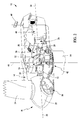
- Figure 2 is a partially cut-away perspective view of a portion of the wind turbine shown in Figure 1.
- Figure 3 is a schematic diagram of the wind turbine shown in Figures 1 and 2.
- Figure 4 is a cross-sectional view of a portion of a rotor hub of the wind turbine shown in Figures 1-3 illustrating an exemplary embodiment of a pitch system for changing a pitch of a rotor blade of the wind turbine shown in Figures 1-3.
- Figure 5 is a flowchart illustrating an exemplary embodiment of a method for controlling a rotor speed of the wind turbine shown in Figures 1-3.
- Figure 6 is a graph illustrating an example of the method shown in Figure 5.
- As used herein, the term "blade" is intended to be representative of any device that provides reactive force when in motion relative to a surrounding fluid. As used herein, the term "wind turbine" is intended to be representative of any device that generates rotational energy from wind energy, and more specifically, converts kinetic energy of wind into mechanical energy. As used herein, the term "wind generator" is intended to be representative of any wind turbine that generates electrical power from rotational energy generated from wind energy, and more specifically, converts mechanical energy converted from kinetic energy of wind to electrical power. As used herein, the term "windmill" is intended to be representative of any wind turbine that uses rotational energy generated from wind energy, and more specifically mechanical energy converted from kinetic energy of wind, for a predetermined purpose other than generating electrical power, such as, but not limited to, pumping a fluid and/or grinding a substance.
- Figure 1 is a perspective of an exemplary embodiment of an
exemplary wind turbine 10. Figure 2 is a partially cut-away perspective view of a portion ofwind turbine 10. Figure 3 is a schematic diagram ofwind turbine 10.Wind turbine 10 described and illustrated herein is a wind generator for generating electrical power from wind energy. However, in some embodiments,wind turbine 10 may be, in addition or alternative to a wind generator, any type of wind turbine, such as, but not limited to, a windmill (not shown). Moreover,wind turbine 10 described and illustrated herein includes a horizontal-axis configuration. However, in some embodiments,wind turbine 10 may include, in addition or alternative to the horizontal-axis configuration, a vertical-axis configuration (not shown).Wind turbine 10 may be coupled to an electrical load (not shown), such as, but not limited to, a power grid (not shown), for receiving electrical power therefrom to drive operation ofwind turbine 10 and/or its associated components and/or for supplying electrical power generated bywind turbine 10 thereto. Although only onewind turbine 10 is shown in Figure 1-3, in some embodiments a plurality ofwind turbines 10 may be grouped together, sometimes referred to as a "wind farm". -
Wind turbine 10 includes abody 16, sometimes referred to as a "nacelle", and a rotor (generally designated by 18) coupled tobody 16 for rotation with respect tobody 16 about an axis ofrotation 20. In the exemplary embodiment,nacelle 16 is mounted on atower 14. However, in some embodiments, in addition or alternative to tower-mountednacelle 16,wind turbine 10 includes anacelle 16 adjacent the ground and/or a surface of water. The height oftower 14 may be any suitable height enablingwind turbine 10 to function as described herein.Rotor 18 includes ahub 22 and a plurality of blades 24 (sometimes referred to as "airfoils") extending radially outwardly fromhub 22 for converting wind energy into rotational energy. Althoughrotor 18 is described and illustrated herein as having threeblades 24,rotor 18 may have any number ofblades 24.Blades 24 may each have any length (whether described herein). For example, in some embodiments one ormore rotor blades 24 are about 0.5 meters long, while in some embodiments one ormore rotor blades 24 are about 50 meters long. Other examples ofblade 24 lengths include 10 meters or less, about 20 meters, about 37 meters, and about 40 meters. Still other examples include rotor blades between about 50 and about 100 meters long. - Despite how
rotor blades 24 are illustrated in Figure 1,rotor 18 may haveblades 24 of any shape, and may haveblades 24 of any type and/or any configuration, whether such shape, type, and/or configuration is described and/or illustrated herein. One example of another type, shape, and/or configuration ofrotor blades 24 is a ducted rotor (not shown) having a turbine (not shown) contained within a duct (not shown). Another example of another type, shape, and/or configuration ofrotor blades 24 is a darrieus wind turbine, sometimes referred to as an "eggbeater" turbine. Yet another example of another type, shape, and/or configuration ofrotor blades 24 is a savonious wind turbine. Even another example of another type, shape, and/or configuration ofrotor blades 24 is a traditional windmill for pumping water, such as, but not limited to, four-bladed rotors having wooden shutters and/or fabric sails. Moreover,wind turbine 10 may, in some embodiments, be a wind turbine whereinrotor 18 generally faces upwind to harness wind energy, and/or may be a wind turbine whereinrotor 18 generally faces downwind to harness energy. Of course, in any embodiments,rotor 18 may not face exactly upwind and/or downwind, but may face generally at any angle (which may be variable) with respect to a direction of the wind to harness energy therefrom. - Referring now to Figures 2 and 3,
wind turbine 10 includes anelectrical generator 26 coupled torotor 18 for generating electrical power from the rotational energy generated byrotor 18.Generator 26 may be any suitable type of electrical generator, such as, but not limited to, a wound rotor induction generator.Generator 26 includes a stator (not shown) and a rotor (not shown).Rotor 18 includes arotor shaft 30 coupled torotor hub 22 for rotation therewith.Generator 26 is coupled torotor shaft 30 such that rotation ofrotor shaft 30 drives rotation of the generator rotor, and therefore operation ofgenerator 26. In the exemplary embodiment, the generator rotor has arotor shaft 28 coupled thereto and coupled torotor shaft 30 such that rotation ofrotor shaft 30 drives rotation of the generator rotor. In other embodiments, the generator rotor is directly coupled torotor shaft 30, sometimes referred to as a "direct-drive wind turbine". In the exemplary embodiment,generator rotor shaft 28 is coupled torotor shaft 28 through agearbox 32, although in other embodimentsgenerator rotor shaft 28 is coupled directly torotor shaft 30. More specifically, in theexemplary embodiment gearbox 32 has alow speed side 34 coupled torotor shaft 30 and ahigh speed side 36 coupled togenerator rotor shaft 28. The torque ofrotor 18 drives the generator rotor to thereby generate variable frequency AC electrical power from rotation ofrotor 18.Generator 26 has an air gap torque between the generator rotor and stator that opposes the torque ofrotor 18. Afrequency converter 38 is coupled togenerator 26 for converting the variable frequency AC to a fixed frequency AC for delivery to an electrical load (not shown), such as, but not limited to a power grid (not shown), coupled togenerator 26.Frequency converter 38 may be located anywhere within or remote towind turbine 10. For example, in the exemplaryembodiment frequency converter 38 is located within a base (not shown) oftower 14. - In some embodiments,
wind turbine 10 may include one ormore control systems 40 coupled to some or all of the components ofwind turbine 10 for generally controlling operation ofwind turbine 10 and/or as some or all of the components thereof (whether such components are described and/or illustrated herein). For example, in the exemplary embodiment control system(s) 40 are coupled to arotor control 41 for generally controllingrotor 18. In the exemplary embodiment, control system(s) 40 is mounted withinnacelle 16. However, additionally or alternatively, one ormore control systems 40 may be remote fromnacelle 16 and/or other components ofwind turbine 10. Control system(s) 40 may be used for, but is not limited to, overall system monitoring and control including, for example, pitch and speed regulation, high-speed shaft and yaw brake application, yaw and pump motor application, and/or fault monitoring. Alternative distributed or centralized control architectures may be used in some embodiments. - In some embodiments,
wind turbine 10 may include a disc brake (not shown) for braking rotation ofrotor 18 to, for example, slow rotation ofrotor 18,brake rotor 18 against full wind torque, and/or reduce the generation of electrical power fromelectrical generator 26. Furthermore, in some embodiments,wind turbine 10 may include ayaw system 42 for rotatingnacelle 16 about an axis ofrotation 44 for changing a yaw ofrotor 18, and more specifically for changing a direction faced byrotor 18 to, for example, adjust an angle between the direction faced byrotor 18 and a direction of wind.Yaw system 42 may be coupled to control system(s) 40 for control thereby. In some embodiments,wind turbine 10 may includeanemometry 46 for measuring wind speed and/or wind direction.Anemometry 46, in some embodiments, may be coupled to control system(s) 40 for sending measurements to control system(s) 40 for processing thereof. For example, and althoughanemometry 46 may be coupled to control system(s) 40 for sending measurements thereto for controlling other operations ofwind turbine 10,anemometry 46 may send measurements to control system(s) 40 for controlling and/or changing a yaw ofrotor 18 usingyaw system 42. Alternatively,anemometry 46 may be coupled directly toyaw system 42 for controlling and/or changing a yaw ofrotor 18. -
Wind turbine 10 may also include a plurality ofsensors 48, each coupled to acorresponding blade 24 for measuring a pitch of eachblade 24, or more specifically an angle of eachblade 24 with respect to a wind direction and/or with respect torotor hub 22.Sensors 48 may be any suitable sensor having any suitable location within or remote towind turbine 10, such as, but not limited to, optical encoders within pitch system 56 (described below). In some embodiments,sensors 48 are coupled to control system(s) 40 for sending pitch measurements to control system(s) 40 for processing thereof. In the exemplary embodiment,wind turbine 10 includes one ormore sensors 50 coupled togenerator rotor shaft 28 for measuring a speed of rotation ofrotor shaft 28 and/or a torque ofgenerator rotor shaft 28. Sensor(s) 50 may be any suitable sensor having any suitable location within or remote towind turbine 10, such as, but not limited to, optical encoders, digital proximity sensors, strain gages, and/or tachometers. In some embodiments, sensor(s) 50 are coupled to control system(s) 40 for sending speed measurements to control system(s) 40 for processing thereof. Moreover, in the exemplary embodiment,wind turbine 10 includes one ormore sensors 52 coupled torotor shaft 30 for measuring a speed of rotation ofrotor shaft 28 and/or a torque ofrotor shaft 30. Sensor(s) 52 may be any suitable sensor having any suitable location within or remote towind turbine 10, such as, but not limited to, optical encoders, digital proximity sensors, piezo-electric transducers, strain gages, and/or tachometers. In some embodiments, sensor(s) 52 are coupled to control system(s) 40 for sending measurements to control system(s) 40 for processing thereof. Furthermore, in the exemplary embodiment,wind turbine 10 includes one ormore sensors 54 coupled togenerator 26 for measuring an electrical power output ofgenerator 26. In some embodiments, sensor(s) 54 are coupled to control system(s) 40 for sending measurements to control system(s) 40 for processing thereof. Sensor(s) 54 may be any suitable sensor having any suitable location within or remote towind turbine 10, such as, but not limited to, Hall effect current transducers (CTs) and/or capacitive voltage transducers (CVTs). -
Wind turbine 10 may also include one or more other sensors (not shown) coupled to one or more components ofwind turbine 10 and/or the electrical load, whether such component(s) are described or illustrated herein, for measuring parameters of such component(s). Such other sensor(s) may include, but are not limited to, sensors configured to measure displacements, yaw, pitch, moments, strain, stress, twist, damage, failure, rotor torque, rotor speed, an anomaly in the electrical load, and/or an anomaly of power supplied to any component ofwind turbine 10. Such other sensors may couple to any component ofwind turbine 10 and/or the electrical load at any location thereof for measuring any parameter thereof, whether such component, location, and/or parameter is described and/or illustrated herein. -
Wind turbine 10 includes a variableblade pitch system 56 for controlling, including but not limited to changing, a pitch angle of rotor blades 24 (shown in Figures 1-3) with respect to a wind direction. Figure 4 is a cross-sectional view of aportion hub 22 illustrating an exemplary embodiment ofpitch system 56.Pitch system 56 may be coupled to control system(s) 40 (shown in Figures 1 and 2) for control thereby.Pitch system 56 includes one or more actuators (e.g.,pitch drive gear 58 andpitch ring gear 60, described below) coupled tohub 22 andblades 24 for changing the pitch angle ofblades 24 by rotatingblades 24 with respect tohub 22. The pitch actuators may include any suitable structure, configuration, arrangement, means, and/or components, whether described and/or illustrated herein, such as, but not limited to, electrical motors, hydraulic cylinders, springs, and/or servomechansims. Moreover, the pitch actuators may be driven by any suitable means, whether described and/or illustrated herein, such as, but not limited to, hydraulic fluid, electrical power, electro-chemical power, and/or mechanical power, such as, but not limited to, spring force. In the exemplary embodiment, the pitch actuators include apitch drive gear 58 that is coupled to apitch ring gear 60, as shown in Figure 4.Pitch ring gear 60 is coupled toblade 24 such that rotation ofpitch drive gear 58 rotatesblade 24 about an axis ofrotation 62 to thereby change the pitch ofblade 24. - In some embodiments, the pitch actuators may be driven by energy extracted from rotational inertia of
rotor 18 and/or a stored energy source (not shown) that supplies components ofwind turbine 10, such as, but not limited to, control system(s) 40 and/orpitch system 56, energy during an anomaly in the electrical load and/or power source coupled towind turbine 10. For example, an anomaly in the electrical load and/or power source may include, but is not limited to, a power failure, an undervoltage condition, an overvoltage condition, and/or an out-of-frequency condition. As such, the stored energy source enables pitching ofblades 24 during the anomaly. Although other stored energy sources may be used, in some embodiments the stored energy source includes hydraulic accumulators, electrical generators, stored spring energy, capacitors, and/or batteries. The stored energy sources may be located anywhere within, on, adjacent to, and/or remote fromwind turbine 10. In some embodiments, the stored energy source stores energy extracted from rotational inertia ofrotor 18, energy stored withinconverter 38, and/or other auxiliary energy sources such as, but not limited to, an auxiliary wind turbine (not shown) coupled towind turbine 10, solar panels, and/or hydro-power installations. - Referring again to Figure 3, in some embodiments, control system(s) 40 include a
bus 62 or other communications device to communicate information. One or more processor(s) 64 are coupled tobus 62 to process information, including information fromanemometry 46,sensors bus 62 to store and transfer information and instructions to be executed by processor(s) 64. RAM(s) 66 (and/or also storage device(s) 68, if included) can also be used to store temporary variables or other intermediate information during execution of instructions by processor(s) 64. Control system(s) 40 may also include one or more read only memories (ROM) 70 and/or other static storage devices coupled tobus 62 to store and provide static (i.e., non-changing) information and instructions to processor(s) 64. Input/output device(s) 72 may include any device known in the art to provide input data to control system(s) 50 and/or to provide outputs, such as, but not limited to, yaw control and/or pitch control outputs. Instructions may be provided to memory from a storage device, such as, but not limited to, a magnetic disk, a read-only memory (ROM) integrated circuit, CD-ROM, and/or DVD, via a remote connection that is either wired or wireless providing access to one or more electronically-accessible media, etc. In some embodiments, hard-wired circuitry can be used in place of or in combination with software instructions. Thus, execution of sequences of instructions is not limited to any specific combination of hardware circuitry and software instructions, whether described and/or illustrated herein. Control system(s) 40 may also include asensor interface 74 that allows control system(s) 40 to communicate withanemometry 46,sensors Sensor interface 74 can be or can include, for example, one or more analog-to-digital converters that convert analog signals into digital signals that can be used by processor(s) 64. - Figure 5 is a flowchart illustrating an exemplary embodiment of a method 100 for controlling a speed of rotor 18 (shown in Figures 1-3). Method 100 includes controlling 102 a torque of generator 26 (shown in Figures 2 and 3) to thereby control a torque of rotor shaft 30 (shown in Figure 2), and alternating between changing 104 an angle of pitch of one or more rotor blades 24 (shown in Figures 1 and 2) to facilitate controlling the speed of
rotor 18 and maintaining 106 the angle of pitch of one ormore rotor blades 24 substantially constant. Controlling 102 the generator torque may include, but is not limited to, selecting generator torque, changing the generator torque, and/or controlling a rate at which the generator torque is changed. The value(s) of generator torque selected, changed, and/or controlled may be any suitable value(s) or range thereof, such as, but not limited to +/- 20% of a predetermined rated torque. Control 102 of generator torque may be performed during any portion of alternating between changing 104 and maintaining 106 pitch angle. For example, generator torque may be controlled 102 during achange 104 of blade pitch angle and/or while pitch angle is maintained 106. In some embodiments, and for example, if controlling 102 generator torque is sufficient to regulate a desired rotational speed ofrotor 18, for example a speed that generates a desired power output ofgenerator 26, blade pitch angle may not be changed 102. Moreover, and for example, in some embodiments generator torque is controlled 102 simultaneously with changing 104 pitch angle, for example, to facilitate preventing operation ofwind turbine 10 at speeds and/or torques above or below predetermined limits. - Changing 104 the pitch angle of
blades 24 may include controlling a rate at which the pitch angle of one ormore blades 24 is changed. The value(s) of blade pitch angle changed 104 and/or maintained 106 may be any suitable value(s) or range thereof, such as, but not limited to, between about -5° and about + 30°. In some embodiments, changing 104 of blade pitch may include a dead band to accommodate, for example, gear backlash. In some embodiments, the dead band is different depending upon a direction of change of pitch angle. - Controlling 102 a torque of
generator rotor shaft 28 and alternating between changing 104 an angle of pitch of one ormore rotor blades 24 and maintaining 106 the angle of pitch of one ormore rotor blades 24 substantially constant may be performed using any suitable structure, process, and/or means. In the exemplary embodiment, method 100controls 102 generator torque and alternates between changing 104 an angle of pitch of one ormore rotor blades 24 and maintaining 106 the angle of pitch of one ormore rotor blades 24 substantially constant using control system(s) 40 (shown in Figures 2 and 3) and input from anemometry 46 (shown in Figures 1 and 2), sensors 48 (shown in Figure 1), 50 (shown in Figure 2), 52 (shown in Figure 2), and/or 54 (shown in Figure 3), and/or other sensor(s). Generator torque may be controlled 102 using any suitable structure, process, and/or means. In the exemplary embodiment, frequency converter 38 (shown in Figures 2 and 3) controls 102 the torque ofgenerator 26 by controlling 105 the air gap torque between the rotor and stator of generator 26 (shown in Figures 2 and 3). Moreover, in the exemplary embodiment,frequency converter 38 controls the torque of generator rotor shaft 28 (shown in Figures 2 and 3) to thereby control the torque ofrotor shaft 30. However, in other embodiments, for example whereinwind turbine 10 is a direct-drive wind turbine,frequency converter 38 may control the torque of a coupling between the generator rotor androtor shaft 30 to thereby control the torque ofrotor shaft 30. Blade pitch may be controlled 102 using suitable structure, process, and/or means. In the exemplary embodiment, blade pitch is controlled 102 using variableblade pitch system 56. - Although method 100 may include controlling 102 generator torque and alternating between changing 104 and maintaining 106 blade pitch during variable speed operation of
wind turbine 10 at or below a predetermined rated wind speed (which may be based on a desired power output of generator 26), in the exemplary embodiment method 100controls 102 generator torque and alternates between changing 104 and maintaining 106 blade pitch to facilitate generally constant speed operation of wind turbine 10 (maintaining a substantially constant speed of rotor 18) at or above the predetermined rated wind speed. In some embodiments, the wind speed is variable above the predetermined rated wind speed such that method 100controls 102 generator torque and alternates between changing 104 and maintaining 106 blade pitch to facilitate generally constant speed operation ofwind turbine 10 during variable wind speeds over the predetermined rated wind speed. - Figure 6 is a graph illustrating an example of method 100 (shown in Figure 5) controlling 102 generator torque and alternating between changing 104 and maintaining 106 a
blade pitch 107 at or above a predetermined rated wind speed. More specifically, as wind speed increases above a predetermined rated wind speed of about 11 m/s, method 100controls 102 generator torque and alternates between changing 104 and maintaining 106blade pitch 107 to facilitate maintaining a generallyconstant rotor speed 109 of about 1440 revolutions per minute (RPM). As such, above a wind speed of about 11 m/s, a generally constantaverage power output 108 of about 1550 kilowatts (KW) is generated from generator 26 (shown in Figures 2 and 3). Of course, Figure 6 is only one example of method 100. Accordingly, wind speed,blade pitch 107,rotor speed 109, andpower output 108 are exemplary values only. Wind speed,blade pitch 107,rotor speed 109, andpower output 108 may have any other suitable value(s) depending upon, for example, a location ofwind turbine 10, design parameters ofwind turbine 10 overall and/or any component thereof, and/or other characteristics ofwind turbine 10. - Referring now to Figures 5 and 6, in the exemplary embodiment alternating between changing 104 and maintaining 106 blade pitch includes changing 110 an angle of one or
more rotor blades 24 in a plurality of successive steps. For example, Figure 6 illustrates an example of method 100 wherein blade pitch is increased in a plurality ofsuccessive steps 112 as wind speed increases above the predetermined rated wind speed of about 11 m/s. Each successive step of blade pitch may be any suitable size, such as, but not limited to 0.3°. Moreover, each successive step may increase blade pitch or decrease blade pitch. In some embodiments, blade pitch is changed in a plurality of successive equal steps that each increase blade pitch. In some embodiments, blade pitch is changed in a plurality of successive equal steps that each decrease blade pitch. In some embodiments, blade pitch is changed in a plurality of successive equal steps, wherein some of the steps increase blade pitch and some of the steps decrease blade pitch. In other embodiments, one or more steps is different from one or more other steps. For example, as illustrated in Figure 6,steps 112 include smaller steps between wind speeds of about 11 m/s and about 13 m/s that transition to larger steps above about 13 m/s of wind speed. - To facilitate achieving a desired average power output of
generator 26 and to facilitate avoiding continuous operation ofwind turbine 10 at speeds and/or torques above or below predetermined limits, changing 104 and/or maintaining 106 blade pitch angle may be based, at least in part, on acomparison 114 between a desired power output and an actual power output ofgenerator 26 generated duringcontrol 102 of generator torque. The actual power output ofgenerator 26 may be measured or calculated. For example, in some embodiments control system(s) 40 receives a power output ofgenerator 26 from sensor 54 (shown in Figures 2 and 3) and changes 104 or maintains 106 blade pitch angle based on the measured power output. In other embodiments, and for example, control system(s) 40 calculates the power output ofgenerator 26 based on a measured torque of generator 26 (in the exemplary embodiment a measured torque ofgenerator rotor shaft 28 received from sensor(s) 50, shown in Figures 2 and 3) or a measured torque ofrotor shaft 30 received from sensor(s) 52 (shown in Figures 2 and 3), and based on a measured rotational speed ofrotor shaft 30 received from sensor(s) 52 or a measured rotational speed of generator 26 (in the exemplary embodiment a measured rotational speed ofgenerator rotor shaft 28 received from sensor(s) 50). - In some embodiments, method 100 includes using a reduced pitch control gain region on all pitch gains to reduce pitch activity when generator speed is adequately controlled by generator torque. More specifically, a reduced pitch control gain region may be used to facilitate smoothing a transition between changing 104 and maintaining 106 blade pitch angle. For example, in some embodiments method 100 includes regulating at least one transition between changing 104 and maintaining 106 blade pitch angle using a gain on a signal based on a difference between a measured torque of
rotor 18 duringcontrol 102 and a substantially constant desired mean reference torque. Furthermore, and for example, in some embodiments method 100 includes regulating at least one transition between changing 104 and maintaining 106 blade pitch angle using a gain on a signal based on a difference between a measured speed ofrotor 18 duringcontrol 102 and a substantially constant desired mean reference speed. Moreover, and for example, in some embodiments method 100 includes regulating at least one transition between changing 104 and maintaining 106 blade pitch angle using a gain on a signal based on a difference between a substantially constant desired mean reference power and either a measured electrical power output ofelectrical generator 26 or the product of a measured torque ofrotor 18 duringcontrol 102 and a measured rotational speed ofrotor 18 duringcontrol 102. Regulating at least one transition between changing 104 and maintaining 106 may include determining whether to change blade pitch angle based on whether the difference between the constant desired mean reference and the measured value (or product of a plurality of measured values) is above a predetermined threshold. For example, in some embodiments if the difference between the constant desired mean reference and the measured value (or product of a plurality of measured values) is above the predetermined threshold, blade pitch angle may be changed 104 in proportion to such difference. Moreover, and for example, in some embodiments if the difference between the constant desired mean reference and the measured value (or product of a plurality of measured values) is below the predetermined threshold, blade pitch angle may be maintained 106. - The herein-described and/or illustrated embodiments are cost-effective and efficient for controlling rotor speed. More specifically, by controlling generator rotor shaft torque to control rotor speed and alternating between changing and maintaining blade pitch angle, the embodiments described and/or illustrated herein may facilitate reducing an amount of pitch movement required to control rotor speed. As such, the embodiments described and/or illustrated herein may facilitate reducing wear on pitch system components, may facilitate reducing parasitic power losses from the pitch system, and/or may facilitate reducing an interaction between blade pitch movements and rotor thrust induced tower oscillations.
- Although the embodiments described and/or illustrated herein are described and/or illustrated with respect to a wind turbine, and more specifically controlling rotor speed of a wind turbine, practice of the embodiments described and/or illustrated herein is not limited to wind turbines. Rather, the embodiments described and/or illustrated herein are applicable to controlling as speed of any rotor having one or more blades.
- Exemplary embodiments are described and/or illustrated herein in detail. The embodiments are not limited to the specific embodiments described herein, but rather, components and steps of each embodiment may be utilized independently and separately from other components and steps described herein. Each component, and each step, can also be used in combination with other components and/or method steps.
- When introducing elements/components/etc. described and/or illustrated herein, the articles "a", "an", "the", "said", and "at least one" are intended to mean that there are one or more of the element(s)/component(s)/etc. The terms "comprising", "including" and "having" are intended to be inclusive and mean that there may be additional element(s)/component(s)/etc. other than the listed element(s)/component(s)/etc.
- While the invention has been described in terms of various specific embodiments, those skilled in the art will recognize that the invention can be practiced with modification within the spirit and scope of the claims.
Claims (10)
- A wind turbine (10) comprising:a rotor (18) comprising a hub (22), at least one rotor blade (24) coupled to said hub, and a rotor shaft (28, 30) coupled to said hub for rotation therewith;a blade pitch (107) actuator coupled to said at least one rotor blade for controlling an angle of pitch of said at least one rotor blade;an electrical generator (26) coupled to said rotor shaft, said electrical generator configured to couple to an electrical load;a frequency converter (38) coupled to said electrical generator; anda processor (64) coupled to said blade pitch actuator and coupled to said frequency converter, said processor configured to control a speed of said rotor by:controlling a torque of said electrical generator using said frequency converter to thereby control a torque of said rotor shaft (28);alternating between changing an angle of pitch of said at least one rotor blade using said blade pitch actuator and maintaining the angle of pitch of said at least one rotor blade substantially constant; andmaintaining a substantially constant rotational speed of said rotor during variable wind speeds above a predetermined rated wind speed.
- A wind turbine (10) in accordance with Claim 1 wherein said processor (64) is configured to regulate at least one transition between changing an angle of pitch of said at least one rotor blade (24) and maintaining the angle of pitch of said at least one rotor blade substantially constant using a gain on a signal based on a difference between a measured torque of said rotor (18) and a substantially constant desired mean reference torque.
- A wind turbine (10) in accordance with Claim 1 wherein said processor (64) is configured to regulate at least one transition between changing an angle of pitch of said at least one rotor blade (24) and maintaining the angle of pitch of said at least one rotor blade substantially constant using a gain on a signal based on a difference between a measured speed of said rotor (18) and a substantially constant desired mean reference speed.
- A wind turbine (10) in accordance with Claim 1 wherein said processor (64) is further configured to regulate at least one transition between changing an angle of pitch of said at least one rotor blade (24) and maintaining the angle of pitch of said at least one rotor blade substantially constant using a gain on a signal based on a difference between a substantially constant desired mean reference power and one of a measured electrical power output (108) of said electrical generator (26) and the product of a measured torque of said rotor and a measured rotational speed of said rotor (18).
- A wind turbine (10) in accordance with Claim 1 wherein said processor (64) is configured to change an angle of pitch of said at least one rotor blade (24) based on a measured electrical power output (108) of said electrical generator (26).
- A wind turbine (10) in accordance with Claim 1 wherein said processor (64) is configured to change an angle of pitch of said at least one rotor blade (24) based on a measured torque of one of said electrical generator (26) and said rotor shaft (28, 30) and a measured rotational speed of one of said electrical generator and said rotor shaft.
- A wind turbine (10) in accordance with Claim 1 wherein said processor (64) is configured to change an angle of pitch of said at least one rotor blade (24) in a plurality of successive steps (112).
- A wind turbine (10) in accordance with Claim 7 wherein said processor (64) is configured to change the angle of pitch of said at least one rotor blade (24) in a plurality of substantially equal steps (112).
- A wind turbine (10) in accordance with Claim 18 wherein at least one step of said plurality of steps (112) is different from at least one other step of said plurality of steps.
- A wind turbine (10) in accordance with Claim 12 wherein said processor (64) is configured to control a torque of said electrical generator (26) during generally constant speed operation of said wind turbine one of at and above a predetermined rated wind speed.
Applications Claiming Priority (1)
| Application Number | Priority Date | Filing Date | Title |
|---|---|---|---|
| US11/368,939 US7352075B2 (en) | 2006-03-06 | 2006-03-06 | Methods and apparatus for controlling rotational speed of a rotor |
Publications (2)
| Publication Number | Publication Date |
|---|---|
| EP1832743A1 true EP1832743A1 (en) | 2007-09-12 |
| EP1832743B1 EP1832743B1 (en) | 2014-05-14 |
Family
ID=38134496
Family Applications (1)
| Application Number | Title | Priority Date | Filing Date |
|---|---|---|---|
| EP07103533.1A Active EP1832743B1 (en) | 2006-03-06 | 2007-03-05 | Method for controlling rotational speed of a rotor |
Country Status (5)
| Country | Link |
|---|---|
| US (1) | US7352075B2 (en) |
| EP (1) | EP1832743B1 (en) |
| CN (1) | CN101042111B (en) |
| DK (1) | DK1832743T3 (en) |
| ES (1) | ES2473343T3 (en) |
Cited By (14)
| Publication number | Priority date | Publication date | Assignee | Title |
|---|---|---|---|---|
| US7352075B2 (en) * | 2006-03-06 | 2008-04-01 | General Electric Company | Methods and apparatus for controlling rotational speed of a rotor |
| EP2088314A2 (en) * | 2008-02-05 | 2009-08-12 | Nordex Energy GmbH | Device for monitoring the rotational speed of a wind turbine |
| EP2146095A2 (en) * | 2008-07-16 | 2010-01-20 | General Electric Company | Use of pitch battery power to start wind turbine during grid loss/black start capability |
| WO2010118777A1 (en) * | 2009-04-16 | 2010-10-21 | Patel Renewable Engineering Ltd. | Apparatus for generating current from natural and renewable energy |
| EP2093418A3 (en) * | 2008-02-21 | 2011-07-06 | Nordex Energy GmbH | Wind turbine with pitch controller |
| WO2011131923A1 (en) * | 2010-04-19 | 2011-10-27 | Philip Wesby | System and method for a vertical axis wind turbine |
| EP2261504B1 (en) * | 2009-06-10 | 2013-09-18 | Wilic S.Àr.L | Wind power electricity generating system and relative control method |
| EP2096300A3 (en) * | 2008-02-29 | 2013-12-11 | General Electric Company | Method of controlling the tip speed ratio of wind turbine blades |
| ITTO20130187A1 (en) * | 2013-03-08 | 2014-09-09 | Avio Spa | AEROGENERATOR, AND ITS CONTROL METHOD |
| EP3059444A1 (en) * | 2015-02-19 | 2016-08-24 | Mitsubishi Heavy Industries, Ltd. | Method and apparatus for controlling wind turbine generator and wind turbine generator |
| RU168788U1 (en) * | 2016-07-18 | 2017-02-21 | Федеральное Государственное Бюджетное Образовательное Учреждение Высшего Образования "Новосибирский Государственный Технический Университет" | Stable AC voltage generating device |
| EP3051124B1 (en) | 2015-01-30 | 2018-06-27 | Adwen GmbH | Method of operating a wind turbine without grid connection and wind turbine |
| FR3067068A1 (en) * | 2017-05-31 | 2018-12-07 | Verteole | WIND MACHINE HAVING A CONTROL UNIT PROVIDING REGULATION OF THE ROTATION SPEED OF THE ROTOR |
| US10436673B2 (en) | 2015-06-30 | 2019-10-08 | Vestas Wind Systems A/S | Method and a device for determining torsional deformation in a drivetrain |
Families Citing this family (83)
| Publication number | Priority date | Publication date | Assignee | Title |
|---|---|---|---|---|
| AT504818A1 (en) * | 2004-07-30 | 2008-08-15 | Windtec Consulting Gmbh | TRANSMISSION TRAIL OF A WIND POWER PLANT |
| JP3918837B2 (en) | 2004-08-06 | 2007-05-23 | 株式会社日立製作所 | Wind power generator |
| DE102004054608B4 (en) * | 2004-09-21 | 2006-06-29 | Repower Systems Ag | Method for controlling a wind turbine and wind turbine with a rotor |
| US7476985B2 (en) * | 2005-07-22 | 2009-01-13 | Gamesa Innovation & Technology, S.L. | Method of operating a wind turbine |
| US7649274B2 (en) * | 2006-02-09 | 2010-01-19 | Windera Power Systems, Inc. | Turbine with constant voltage and frequency output |
| DE102006007919B4 (en) * | 2006-02-21 | 2008-01-24 | Nordex Energy Gmbh | Method for operating a wind energy plant |
| US8460223B2 (en) * | 2006-03-15 | 2013-06-11 | Hill-Rom Services Pte. Ltd. | High frequency chest wall oscillation system |
| US7635922B2 (en) * | 2006-04-03 | 2009-12-22 | C.E. Niehoff & Co. | Power control system and method |
| US7560823B2 (en) * | 2006-06-30 | 2009-07-14 | General Electric Company | Wind energy system and method of operation thereof |
| DE102006040970B4 (en) * | 2006-08-19 | 2009-01-22 | Nordex Energy Gmbh | Method for operating a wind energy plant |
| US7417332B2 (en) * | 2006-08-24 | 2008-08-26 | General Electric Company | Method and apparatus of monitoring a machine |
| US7420289B2 (en) * | 2006-12-06 | 2008-09-02 | General Electric Company | Method for predicting a power curve for a wind turbine |
| US9194362B2 (en) | 2006-12-21 | 2015-11-24 | Green Energy Technologies, Llc | Wind turbine shroud and wind turbine system using the shroud |
| US8257019B2 (en) * | 2006-12-21 | 2012-09-04 | Green Energy Technologies, Llc | Shrouded wind turbine system with yaw control |
| DE102007003618A1 (en) * | 2007-01-18 | 2008-07-24 | Voith Patent Gmbh | Power generation plant driven by a wind or water flow |
| JP2008184932A (en) * | 2007-01-29 | 2008-08-14 | Mitsubishi Heavy Ind Ltd | Wind power generator |
| ES2341820B1 (en) * | 2007-01-31 | 2011-05-13 | GAMESA INNOVATION & TECHNOLOGY, S.L. | A METHOD TO ELIMINATE THE IMPACT OF BACKWARDS ON THE MULTIPLIER OF AN AEROGENERATOR. |
| DE102007019513B4 (en) * | 2007-04-25 | 2012-03-15 | Aerodyn Engineering Gmbh | Wind turbine |
| WO2008131776A2 (en) * | 2007-04-30 | 2008-11-06 | Vestas Wind Systems A/S | A method of operating a wind turbine, a wind turbine and a cluster of wind turbines |
| ATE483910T1 (en) * | 2007-04-30 | 2010-10-15 | Vestas Wind Sys As | METHOD FOR OPERATING A WIND TURBINE WITH ANGLE CONTROL |
| US20080284171A1 (en) * | 2007-05-16 | 2008-11-20 | V3 Technologies, L.L.C. | Augmented wind power generation system using an antecedent atmospheric sensor and method of operation |
| DK2009279T3 (en) * | 2007-06-28 | 2015-11-30 | Siemens Ag | Method for controlling at least one element of a first component of a wind turbine, control device and use of the control device |
| WO2009050157A2 (en) * | 2007-10-15 | 2009-04-23 | Suzlon Energy Gmbh | Wind energy installation with enhanced overvoltage protection |
| CN101971481B (en) * | 2007-11-05 | 2014-04-09 | 托马斯·斯图尔特·贝尔纳茨 | Horizontal axis wind turbine rotor assembly with lifting body rotor blades |
| US8805595B2 (en) * | 2008-01-17 | 2014-08-12 | General Electric Company | Wind turbine arranged for independent operation of its components and related method and computer program |
| DE102008010543A1 (en) * | 2008-02-22 | 2009-08-27 | Nordex Energy Gmbh | Method for operating a wind turbine and wind turbine |
| US8004100B2 (en) * | 2008-03-14 | 2011-08-23 | General Electric Company | Model based wind turbine drive train vibration damper |
| US8038395B2 (en) * | 2008-03-28 | 2011-10-18 | General Electric Company | Pulsed torque control of wind turbine pitch systems |
| US8714928B2 (en) * | 2008-06-06 | 2014-05-06 | General Electric Company | Rotor assembly for a wind turbine and method of assembling the same |
| WO2009155467A2 (en) * | 2008-06-18 | 2009-12-23 | Duffey Christopher K | Variable speed synchronous generator |
| ES2411355T5 (en) * | 2008-06-30 | 2019-05-27 | Vestas Wind Sys As | Restriction of power of wind turbines |
| US8109711B2 (en) | 2008-07-18 | 2012-02-07 | Honeywell International Inc. | Tethered autonomous air vehicle with wind turbines |
| JP4995209B2 (en) * | 2009-01-05 | 2012-08-08 | 三菱重工業株式会社 | Wind power generator and wind direction estimating method for wind power generator |
| US20100135798A1 (en) * | 2009-02-10 | 2010-06-03 | General Electric Company | Wind turbine noise controls |
| US8008797B2 (en) * | 2009-02-13 | 2011-08-30 | Bernard Joseph Simon | System for converting wind power to electrcial power with transmission |
| JP2010275926A (en) * | 2009-05-28 | 2010-12-09 | Zephyr Corp | Wind power generation control device and wind power generation control method |
| US8222757B2 (en) * | 2009-06-05 | 2012-07-17 | General Electric Company | Load identification system and method of assembling the same |
| US7902689B2 (en) * | 2009-07-07 | 2011-03-08 | General Electric Company | Method and system for noise controlled operation of a wind turbine |
| US7945350B2 (en) * | 2009-07-07 | 2011-05-17 | General Electric Company | Wind turbine acoustic emission control system and method |
| US7763989B2 (en) * | 2009-07-07 | 2010-07-27 | General Electric Company | Method and apparatus for controlling the tip speed of a blade of a wind turbine |
| ES2358140B1 (en) * | 2009-10-23 | 2012-04-12 | Gamesa Innovation & Technology S.L | METHODS OF AIRCRAFT CONTROL TO IMPROVE ENERGY PRODUCTION. |
| US10137542B2 (en) | 2010-01-14 | 2018-11-27 | Senvion Gmbh | Wind turbine rotor blade components and machine for making same |
| ES2510398T3 (en) | 2010-01-14 | 2014-10-21 | Neptco, Inc. | Wind turbine rotor blade components and methods for manufacturing them |
| JP5562274B2 (en) * | 2010-03-12 | 2014-07-30 | Ntn株式会社 | Wear detection device, wind power generation apparatus including the same, and wear detection method |
| DE102010019444A1 (en) * | 2010-05-05 | 2011-11-10 | Robert Bosch Gmbh | rotor blade |
| US8222760B2 (en) * | 2010-06-29 | 2012-07-17 | General Electric Company | Method for controlling a proximity sensor of a wind turbine |
| US8115330B2 (en) * | 2010-06-29 | 2012-02-14 | General Electric Company | Wind turbine and method for operating a wind turbine |
| DE102010044433A1 (en) * | 2010-09-06 | 2012-03-08 | Nordex Energy Gmbh | Method for controlling the speed of a wind turbine |
| WO2012118549A1 (en) | 2010-12-09 | 2012-09-07 | Northern Power Systems, Inc. | Systems for load reduction in a tower of an idled wind-power unit and methods thereof |
| JP2012143079A (en) | 2010-12-28 | 2012-07-26 | Mitsubishi Heavy Ind Ltd | Cable supporter |
| JP5455890B2 (en) * | 2010-12-28 | 2014-03-26 | 三菱重工業株式会社 | Wind turbine generator control device, wind turbine generator system, and wind turbine generator control method |
| US20110210551A1 (en) * | 2011-02-07 | 2011-09-01 | Scholte-Wassink Hartmut | Method and system for testing a mechanical brake of a wind rotor shaft of a wind turbine |
| US20120207604A1 (en) * | 2011-02-14 | 2012-08-16 | Gregory Lee Hobson | Incapsulated horizontal wind turbine |
| BRPI1100052A2 (en) * | 2011-02-23 | 2016-05-03 | Mitsubishi Heavy Ind Ltd | controller for a wind turbine generator, wind turbine generator, and method for controlling a wind turbine generator. |
| EP2807742A2 (en) | 2011-04-11 | 2014-12-03 | Faculty of Electrical Engineering and Computing | Generator-fault-tolerant control for a variable-speed variable-pitch wind turbine |
| US8258643B2 (en) * | 2011-10-11 | 2012-09-04 | General Electric Company | Method and system for control of wind turbines |
| CN102392792B (en) * | 2011-11-05 | 2013-04-24 | 太原科技大学 | Vertical shaft wind-driven generation system structure and control method thereof |
| EP2599995B1 (en) * | 2011-11-30 | 2015-10-28 | Siemens Aktiengesellschaft | Wind turbine control system |
| ES2407955B1 (en) * | 2011-12-12 | 2014-05-08 | Acciona Windpower, S.A. | AEROGENERATOR CONTROL PROCEDURE |
| EP2610484A1 (en) * | 2011-12-26 | 2013-07-03 | Vestas Wind Systems A/S | Method for controlling a wind turbine |
| US8704393B2 (en) * | 2012-08-09 | 2014-04-22 | General Electric Company | System and method for controlling speed and torque of a wind turbine during post-rated wind speed conditions |
| US9709034B2 (en) * | 2012-08-14 | 2017-07-18 | Vestas Wind Systems A/S | Partial-load de-rating for wind turbine control |
| US9303626B2 (en) | 2012-12-18 | 2016-04-05 | General Electric Company | Control system and method for mitigating loads during yaw error on a wind turbine |
| EP2754886B1 (en) * | 2013-01-14 | 2016-01-06 | ALSTOM Renewable Technologies | Method of operating a wind turbine rotational system and wind turbine rotational system |
| US20150115607A1 (en) * | 2013-10-27 | 2015-04-30 | Lev Stepanov | Method of increasing of sensitivity and productivity of the wind generator with vertical axis at weak winds and device for his realization |
| CN103615356B (en) * | 2013-12-12 | 2016-02-10 | 北京金风科创风电设备有限公司 | Wind turbine generator set full-load working condition constant power control method and device and wind turbine generator set |
| WO2015197071A1 (en) * | 2014-06-26 | 2015-12-30 | Vestas Wind Systems A/S | Wind turbine controller with pitch feedback control loop in partial load |
| EP2963282B1 (en) * | 2014-07-04 | 2018-10-24 | Siemens Aktiengesellschaft | Mounting ring arrangement for wind turbine blade |
| US10364797B2 (en) | 2015-01-29 | 2019-07-30 | Vestas Wind Systems A/S | Partial and full load controllers of a wind turbine |
| CN107407258B (en) * | 2015-03-05 | 2020-02-14 | 维斯塔斯风力系统集团公司 | Power ramp of turbine from low power mode |
| US10294920B2 (en) * | 2015-09-23 | 2019-05-21 | General Electric Company | Wind turbine and method for operating a wind turbine |
| CN108291523B (en) * | 2015-11-18 | 2020-03-03 | 维斯塔斯风力系统集团公司 | Control system and method for a wind turbine with multiple rotors |
| US20190063401A1 (en) * | 2016-04-15 | 2019-02-28 | Damodaran Ethirajulu | Variable tilting blade twin turbine wind mill |
| US9960600B1 (en) | 2016-10-31 | 2018-05-01 | General Electric Company | Detection and mitigation of instability of synchronous machines |
| US10634121B2 (en) | 2017-06-15 | 2020-04-28 | General Electric Company | Variable rated speed control in partial load operation of a wind turbine |
| CN109973300B (en) * | 2017-12-27 | 2021-01-22 | 北京金风科创风电设备有限公司 | Power control method and device for wind generating set |
| DE102018113706A1 (en) * | 2018-06-08 | 2019-12-12 | Wobben Properties Gmbh | Method for operating a wind energy plant, wind energy plant and wind farm |
| WO2020011322A1 (en) * | 2018-07-09 | 2020-01-16 | Vestas Wind Systems A/S | Multirotor wind turbine power boost strategy |
| CN109139365B (en) * | 2018-09-03 | 2020-03-03 | 浙江运达风电股份有限公司 | Optimal rotating speed control method for improving power generation performance of large wind turbine generator |
| US11261844B2 (en) * | 2019-02-28 | 2022-03-01 | General Electric Company | System and method for predicting wind turbine shutdowns due to excessive vibration |
| CN110067703B (en) * | 2019-05-28 | 2023-12-29 | 华北电力大学 | Worm type synchronous variable pitch wind turbine generator and control method |
| CN112943530B (en) * | 2019-12-11 | 2022-11-08 | 新疆金风科技股份有限公司 | Control method and device of wind generating set |
| CN111637025B (en) * | 2020-06-12 | 2022-05-03 | 云南省能源研究院有限公司 | Detection method of wind driven generator |
Citations (5)
| Publication number | Priority date | Publication date | Assignee | Title |
|---|---|---|---|---|
| EP0120654A1 (en) * | 1983-03-23 | 1984-10-03 | The English Electric Company Limited | Power generating equipment |
| US20040207208A1 (en) * | 1997-08-08 | 2004-10-21 | Mikhail Amir S | Variable speed wind turbine generator |
| US20050012339A1 (en) * | 2003-05-07 | 2005-01-20 | Mikhail Amir S. | Variable speed distributed drive train wind turbine system |
| JP2005042603A (en) * | 2003-07-28 | 2005-02-17 | Toyo Electric Mfg Co Ltd | Overspeed control torque command circuit for windmill by pwm converter |
| US20060033338A1 (en) * | 2004-05-11 | 2006-02-16 | Wilson Kitchener C | Wind flow estimation and tracking using tower dynamics |
Family Cites Families (19)
| Publication number | Priority date | Publication date | Assignee | Title |
|---|---|---|---|---|
| US4495423A (en) * | 1981-09-10 | 1985-01-22 | Felt Products Mfg. Co. | Wind energy conversion system |
| JPS59183085A (en) * | 1983-04-01 | 1984-10-18 | Yamaha Motor Co Ltd | Windmill equipped with rotating speed control device for rotor |
| US4703189A (en) * | 1985-11-18 | 1987-10-27 | United Technologies Corporation | Torque control for a variable speed wind turbine |
| US4695736A (en) * | 1985-11-18 | 1987-09-22 | United Technologies Corporation | Variable speed wind turbine |
| US4700081A (en) * | 1986-04-28 | 1987-10-13 | United Technologies Corporation | Speed avoidance logic for a variable speed wind turbine |
| US5083039B1 (en) * | 1991-02-01 | 1999-11-16 | Zond Energy Systems Inc | Variable speed wind turbine |
| US5155375A (en) * | 1991-09-19 | 1992-10-13 | U.S. Windpower, Inc. | Speed control system for a variable speed wind turbine |
| JP3844825B2 (en) * | 1996-12-03 | 2006-11-15 | 関西電力株式会社 | Windmill start promotion device |
| US6137187A (en) * | 1997-08-08 | 2000-10-24 | Zond Energy Systems, Inc. | Variable speed wind turbine generator |
| DE19844258A1 (en) * | 1998-09-26 | 2000-03-30 | Dewind Technik Gmbh | Wind turbine |
| DE10134883A1 (en) * | 2001-07-18 | 2003-01-30 | Abb Research Ltd | Method and device for speed-adjustable power electronic control of a gearless wind turbine |
| US6921985B2 (en) | 2003-01-24 | 2005-07-26 | General Electric Company | Low voltage ride through for wind turbine generators |
| US7233129B2 (en) * | 2003-05-07 | 2007-06-19 | Clipper Windpower Technology, Inc. | Generator with utility fault ride-through capability |
| DE10361443B4 (en) * | 2003-12-23 | 2005-11-10 | Voith Turbo Gmbh & Co. Kg | Control for a wind turbine with hydrodynamic transmission |
| US7118339B2 (en) | 2004-06-30 | 2006-10-10 | General Electric Company | Methods and apparatus for reduction of asymmetric rotor loads in wind turbines |
| WO2006007838A1 (en) | 2004-07-23 | 2006-01-26 | Vestas Wind Systems A/S | Method of controlling the pitch velocity of a wind turbine blade and control system therefore |
| DE102005029000B4 (en) * | 2005-06-21 | 2007-04-12 | Repower Systems Ag | Method and system for regulation of rotational speed of rotor on wind energy unit with generator and energy blade using pitch angle control device and torque control device to determine rotational speed set values |
| AU2006336347B2 (en) * | 2006-01-20 | 2011-09-22 | Southwest Windpower, Inc. | Stall controller and triggering condition control features for a wind turbine |
| US7352075B2 (en) * | 2006-03-06 | 2008-04-01 | General Electric Company | Methods and apparatus for controlling rotational speed of a rotor |
-
2006
- 2006-03-06 US US11/368,939 patent/US7352075B2/en active Active
-
2007
- 2007-03-05 DK DK07103533.1T patent/DK1832743T3/en active
- 2007-03-05 EP EP07103533.1A patent/EP1832743B1/en active Active
- 2007-03-05 ES ES07103533.1T patent/ES2473343T3/en active Active
- 2007-03-06 CN CN200710092398.6A patent/CN101042111B/en active Active
Patent Citations (5)
| Publication number | Priority date | Publication date | Assignee | Title |
|---|---|---|---|---|
| EP0120654A1 (en) * | 1983-03-23 | 1984-10-03 | The English Electric Company Limited | Power generating equipment |
| US20040207208A1 (en) * | 1997-08-08 | 2004-10-21 | Mikhail Amir S | Variable speed wind turbine generator |
| US20050012339A1 (en) * | 2003-05-07 | 2005-01-20 | Mikhail Amir S. | Variable speed distributed drive train wind turbine system |
| JP2005042603A (en) * | 2003-07-28 | 2005-02-17 | Toyo Electric Mfg Co Ltd | Overspeed control torque command circuit for windmill by pwm converter |
| US20060033338A1 (en) * | 2004-05-11 | 2006-02-16 | Wilson Kitchener C | Wind flow estimation and tracking using tower dynamics |
Non-Patent Citations (2)
| Title |
|---|
| HAU E: "Windkraftanlagen, 10.3 LEISTUNGS- UND DREHZAHLREGELUNG MIT BLATTEINSTELLWINKELVERSTELLUNG", WINDKRAFTANLAGEN, XX, XX, 1995, pages 318 - 333, XP002398040 * |
| LEITHEAD W E ET AL: "ROLE AND OBJECTIVES OF CONTROL FOR WIND TURBINES", IEE PROCEEDINGS C. GENERATION, TRANSMISSION, DISTRIBUTION, INSTITUTION OF ELECTRICAL ENGINEERS. STEVENAGE, GB, vol. 138, no. 2 PART C, 1 March 1991 (1991-03-01), pages 135 - 148, XP000219783, ISSN: 0143-7046 * |
Cited By (24)
| Publication number | Priority date | Publication date | Assignee | Title |
|---|---|---|---|---|
| US7352075B2 (en) * | 2006-03-06 | 2008-04-01 | General Electric Company | Methods and apparatus for controlling rotational speed of a rotor |
| EP2088314A3 (en) * | 2008-02-05 | 2011-07-06 | Nordex Energy GmbH | Device for monitoring the rotational speed of a wind turbine |
| EP2088314A2 (en) * | 2008-02-05 | 2009-08-12 | Nordex Energy GmbH | Device for monitoring the rotational speed of a wind turbine |
| EP2088314B1 (en) | 2008-02-05 | 2015-06-03 | Nordex Energy GmbH | Device for monitoring the rotational speed of a wind turbine |
| EP2093418A3 (en) * | 2008-02-21 | 2011-07-06 | Nordex Energy GmbH | Wind turbine with pitch controller |
| EP2096300A3 (en) * | 2008-02-29 | 2013-12-11 | General Electric Company | Method of controlling the tip speed ratio of wind turbine blades |
| EP2096300B1 (en) | 2008-02-29 | 2019-04-10 | General Electric Company | Method of controlling the tip speed ratio of wind turbine blades |
| EP2146095A2 (en) * | 2008-07-16 | 2010-01-20 | General Electric Company | Use of pitch battery power to start wind turbine during grid loss/black start capability |
| EP2146095A3 (en) * | 2008-07-16 | 2012-04-04 | General Electric Company | Use of pitch battery power to start wind turbine during grid loss/black start capability |
| US8344533B2 (en) | 2008-07-16 | 2013-01-01 | General Electric Company | Use of pitch battery power to start wind turbine during grid loss/black start capability |
| CN101629553B (en) * | 2008-07-16 | 2013-09-18 | 通用电气公司 | Wind generation device, and method for operation of wind generation device during network loss |
| CN101629553A (en) * | 2008-07-16 | 2010-01-20 | 通用电气公司 | Use of pitch battery power to start wind turbine during grid loss/black start capability |
| WO2010118777A1 (en) * | 2009-04-16 | 2010-10-21 | Patel Renewable Engineering Ltd. | Apparatus for generating current from natural and renewable energy |
| EP2261504B1 (en) * | 2009-06-10 | 2013-09-18 | Wilic S.Àr.L | Wind power electricity generating system and relative control method |
| US9879650B2 (en) | 2010-04-19 | 2018-01-30 | Philip B. Wesby | System and method for a vertical axis wind turbine |
| WO2011131923A1 (en) * | 2010-04-19 | 2011-10-27 | Philip Wesby | System and method for a vertical axis wind turbine |
| EP2775139A1 (en) * | 2013-03-08 | 2014-09-10 | Ge Avio S.r.l. | Wind turbine , and control method thereof |
| ITTO20130187A1 (en) * | 2013-03-08 | 2014-09-09 | Avio Spa | AEROGENERATOR, AND ITS CONTROL METHOD |
| EP3051124B1 (en) | 2015-01-30 | 2018-06-27 | Adwen GmbH | Method of operating a wind turbine without grid connection and wind turbine |
| US10774808B2 (en) | 2015-01-30 | 2020-09-15 | Adwen Gmbh | Method of operating a wind turbine without grid connection and wind turbine |
| EP3059444A1 (en) * | 2015-02-19 | 2016-08-24 | Mitsubishi Heavy Industries, Ltd. | Method and apparatus for controlling wind turbine generator and wind turbine generator |
| US10436673B2 (en) | 2015-06-30 | 2019-10-08 | Vestas Wind Systems A/S | Method and a device for determining torsional deformation in a drivetrain |
| RU168788U1 (en) * | 2016-07-18 | 2017-02-21 | Федеральное Государственное Бюджетное Образовательное Учреждение Высшего Образования "Новосибирский Государственный Технический Университет" | Stable AC voltage generating device |
| FR3067068A1 (en) * | 2017-05-31 | 2018-12-07 | Verteole | WIND MACHINE HAVING A CONTROL UNIT PROVIDING REGULATION OF THE ROTATION SPEED OF THE ROTOR |
Also Published As
| Publication number | Publication date |
|---|---|
| CN101042111A (en) | 2007-09-26 |
| ES2473343T3 (en) | 2014-07-04 |
| EP1832743B1 (en) | 2014-05-14 |
| CN101042111B (en) | 2014-08-13 |
| DK1832743T3 (en) | 2014-06-30 |
| US7352075B2 (en) | 2008-04-01 |
| US20070205602A1 (en) | 2007-09-06 |
Similar Documents
| Publication | Publication Date | Title |
|---|---|---|
| US7352075B2 (en) | Methods and apparatus for controlling rotational speed of a rotor | |
| US8013460B2 (en) | Method and apparatus for controlling noise levels of a turbine with minimal loss in energy yield | |
| US7874797B2 (en) | Methods and apparatus for balancing a rotor | |
| EP1788237B1 (en) | Method and apparatus for wind turbine braking | |
| US8738192B2 (en) | Methods for operating a wind turbine | |
| EP2273105B1 (en) | Method and system for noise controlled operation of a wind turbine | |
| EP2273109B1 (en) | Wind turbine acoustic emission control system and method | |
| EP2108825B1 (en) | System and method for reducing rotor loads in a wind turbine upon detection of blade-pitch failure and loss of counter-torque | |
| EP1906192B1 (en) | Apparatus for evaluating sensors and/or for controlling operation of an apparatus that includes a sensor | |
| EP2306003B1 (en) | System and methods for controlling a wind turbine | |
| US8038395B2 (en) | Pulsed torque control of wind turbine pitch systems |
Legal Events
| Date | Code | Title | Description |
|---|---|---|---|
| PUAI | Public reference made under article 153(3) epc to a published international application that has entered the european phase |
Free format text: ORIGINAL CODE: 0009012 |
|
| AK | Designated contracting states |
Kind code of ref document: A1 Designated state(s): AT BE BG CH CY CZ DE DK EE ES FI FR GB GR HU IE IS IT LI LT LU LV MC MT NL PL PT RO SE SI SK TR |
|
| AX | Request for extension of the european patent |
Extension state: AL BA HR MK YU |
|
| RIN1 | Information on inventor provided before grant (corrected) |
Inventor name: HOLLEY, WILLIAM EDWIN Inventor name: PIERCE, KIRK GEE Inventor name: CUNNINGHAM, JOHN NOEL Inventor name: WILLEY, LAWRENCE DONALD Inventor name: GEBHARDT, ERIC Inventor name: UPHUES, ULRICH |
|
| 17P | Request for examination filed |
Effective date: 20080312 |
|
| AKX | Designation fees paid |
Designated state(s): DE DK ES |
|
| 17Q | First examination report despatched |
Effective date: 20080604 |
|
| REG | Reference to a national code |
Ref country code: DE Ref legal event code: R079 Ref document number: 602007036665 Country of ref document: DE Free format text: PREVIOUS MAIN CLASS: F03D0007040000 Ipc: F03D0007020000 |
|
| GRAP | Despatch of communication of intention to grant a patent |
Free format text: ORIGINAL CODE: EPIDOSNIGR1 |
|
| RIC1 | Information provided on ipc code assigned before grant |
Ipc: F03D 7/02 20060101AFI20131203BHEP Ipc: F03D 7/06 20060101ALI20131203BHEP Ipc: F03D 7/04 20060101ALI20131203BHEP |
|
| INTG | Intention to grant announced |
Effective date: 20140109 |
|
| GRAS | Grant fee paid |
Free format text: ORIGINAL CODE: EPIDOSNIGR3 |
|
| GRAA | (expected) grant |
Free format text: ORIGINAL CODE: 0009210 |
|
| AK | Designated contracting states |
Kind code of ref document: B1 Designated state(s): DE DK ES |
|
| REG | Reference to a national code |
Ref country code: DK Ref legal event code: T3 Effective date: 20140624 |
|
| REG | Reference to a national code |
Ref country code: DE Ref legal event code: R096 Ref document number: 602007036665 Country of ref document: DE Effective date: 20140703 |
|
| REG | Reference to a national code |
Ref country code: ES Ref legal event code: FG2A Ref document number: 2473343 Country of ref document: ES Kind code of ref document: T3 Effective date: 20140704 |
|
| REG | Reference to a national code |
Ref country code: DE Ref legal event code: R097 Ref document number: 602007036665 Country of ref document: DE |
|
| PLBE | No opposition filed within time limit |
Free format text: ORIGINAL CODE: 0009261 |
|
| STAA | Information on the status of an ep patent application or granted ep patent |
Free format text: STATUS: NO OPPOSITION FILED WITHIN TIME LIMIT |
|
| 26N | No opposition filed |
Effective date: 20150217 |
|
| REG | Reference to a national code |
Ref country code: DE Ref legal event code: R097 Ref document number: 602007036665 Country of ref document: DE Effective date: 20150217 |
|
| PGFP | Annual fee paid to national office [announced via postgrant information from national office to epo] |
Ref country code: DK Payment date: 20230221 Year of fee payment: 17 |
|
| PGFP | Annual fee paid to national office [announced via postgrant information from national office to epo] |
Ref country code: DE Payment date: 20230221 Year of fee payment: 17 |
|
| P01 | Opt-out of the competence of the unified patent court (upc) registered |
Effective date: 20230530 |
|
| PGFP | Annual fee paid to national office [announced via postgrant information from national office to epo] |
Ref country code: ES Payment date: 20230403 Year of fee payment: 17 |
|
| REG | Reference to a national code |
Ref country code: DE Ref legal event code: R081 Ref document number: 602007036665 Country of ref document: DE Owner name: GENERAL ELECTRIC RENOVABLES ESPANA, S.L., ES Free format text: FORMER OWNER: GENERAL ELECTRIC CO., SCHENECTADY, N.Y., US |