EP1832710B1 - Device for loading a drilling installation and drilling apparatus - Google Patents
Device for loading a drilling installation and drilling apparatus Download PDFInfo
- Publication number
- EP1832710B1 EP1832710B1 EP06004639A EP06004639A EP1832710B1 EP 1832710 B1 EP1832710 B1 EP 1832710B1 EP 06004639 A EP06004639 A EP 06004639A EP 06004639 A EP06004639 A EP 06004639A EP 1832710 B1 EP1832710 B1 EP 1832710B1
- Authority
- EP
- European Patent Office
- Prior art keywords
- magazine
- drilling
- rod
- tubes
- manipulator
- Prior art date
- Legal status (The legal status is an assumption and is not a legal conclusion. Google has not performed a legal analysis and makes no representation as to the accuracy of the status listed.)
- Not-in-force
Links
- 238000005553 drilling Methods 0.000 title claims abstract description 52
- 238000009434 installation Methods 0.000 title 1
- 230000033001 locomotion Effects 0.000 claims description 11
- 239000011435 rock Substances 0.000 claims description 4
- 210000000078 claw Anatomy 0.000 claims 2
- 238000000034 method Methods 0.000 description 8
- 230000005540 biological transmission Effects 0.000 description 2
- 238000006073 displacement reaction Methods 0.000 description 2
- 238000009933 burial Methods 0.000 description 1
- 230000001419 dependent effect Effects 0.000 description 1
- 238000011084 recovery Methods 0.000 description 1
Images


Classifications
-
- E—FIXED CONSTRUCTIONS
- E21—EARTH OR ROCK DRILLING; MINING
- E21B—EARTH OR ROCK DRILLING; OBTAINING OIL, GAS, WATER, SOLUBLE OR MELTABLE MATERIALS OR A SLURRY OF MINERALS FROM WELLS
- E21B19/00—Handling rods, casings, tubes or the like outside the borehole, e.g. in the derrick; Apparatus for feeding the rods or cables
- E21B19/20—Combined feeding from rack and connecting, e.g. automatically
-
- E—FIXED CONSTRUCTIONS
- E21—EARTH OR ROCK DRILLING; MINING
- E21B—EARTH OR ROCK DRILLING; OBTAINING OIL, GAS, WATER, SOLUBLE OR MELTABLE MATERIALS OR A SLURRY OF MINERALS FROM WELLS
- E21B19/00—Handling rods, casings, tubes or the like outside the borehole, e.g. in the derrick; Apparatus for feeding the rods or cables
- E21B19/14—Racks, ramps, troughs or bins, for holding the lengths of rod singly or connected; Handling between storage place and borehole
- E21B19/146—Carousel systems, i.e. rotating rack systems
Definitions
- the invention relates to a drilling rig, in particular a burial or rock drilling apparatus, according to the preamble of claim 1.
- a drill includes, inter alia, a device for loading a drilling device of the drill with a double linkage, with a rod magazine, the multiple receptacles for inner tubes and outer tubes of the double rod has.
- the invention is characterized inter alia by a manipulator for gripping and method of the pipes in and out of the rod magazine.
- a generic drill is from the JP 08-296389 A known.
- Another device for feeding a drill with a drill string is for example from DE 101 08 696 B4 known.
- the known device has a respect to a carriage fixed rod magazine with a plurality of pipe cradles, in which the outer and inner tubes of the double rod can be added to each other plugged.
- the tubes are arranged part-ring around a longitudinal axis.
- a gripper is provided, which is rotatable about the longitudinal axis of the magazine.
- individual storage positions can be covered and difficult to see by the operator, which can be unfavorable for manual operation.
- Another device with a fixed, partially cylindrical magazine and a pivotable about the cylinder axis gripper is from the EP 0 379 187 A1 known.
- the DE 198 10 707 A1 discloses a drill with a drum magazine, on the circumference of inner tubes and outer tubes of a double linkage are each arranged in groups next to each other. After DE 198 10 707 A1 a pinch roller arrangement is provided, with which an inner tube is moved axially out of the drum magazine. Subsequently, the inner tube is again lowered axially and thereby introduced into an adjacent outer tube. The combination of outer tube and inner tube is then pivoted into the drilling axis, where it is detected by a clamping pliers.
- the known device has a drum magazine, in which the inner tubes and outer tubes are arranged at separate locations, in the radial direction one behind the other.
- a pulling and setting device is provided, with which initially the inner rod is removed from the magazine upwards, is positioned coaxially over the outer tube and then retracted into this. The two tubes are then moved together into the drilling axis.
- a drilling device in which the inner tubes and outer tubes are stored separately.
- the drill drive is moved back axially and transported the outer tube in the drilling position.
- the inner tube is inserted into the outer tube by moving the drill drive and also the outer tube connected to the drill drive.
- Another rod magazine which is intended for a separate storage of inner and outer tubes, goes out of the DE 103 41 437 A1 out.
- the EP 0 565 502 B2 discloses a rock drilling machine with a box magazine in which pipe elements are arranged one above the other.
- More box magazines are from the DE 198 30 447 A1 and the DE 299 03 909 U1 known.
- the US 3,734,209 describes a drilling apparatus in which twin well links are stored side by side on a feed chute.
- the object of the invention is to provide a drill, in particular an earth or rock drill, with a device for feeding a drilling device of the drill with a double rod, which ensures a particularly high reliability and reliability in a compact and simple design of the device.
- the rod magazine as a rotatable Revolver magazine is formed with double receptacles, which each have a holding element for an outer tube and a further holding element for an inner tube arranged within the outer tube.
- a basic idea of the invention can be seen in a design of a revolver magazine with double receptacles, which each allow a bearing of a tube pair consisting of an inner tube and an outer tube in the same place.
- the inner tubes and the outer tubes can be held in a nested position in the magazine.
- the tubes can thus be magazined in exactly the arrangement in which they are also in the double-tube drilling.
- the number of Umgreifvonreae required during the loading of the drilling device or magazining is reduced, which ensures a particularly reliable operation, in particular a particularly simple manipulator control, with a simple apparatus design.
- a revolver magazine may in particular be understood to mean a magazine in which the receptacles and / or the tubes received are arranged around the axis of rotation of the magazine, the longitudinal axes of the tubes received being suitably parallel to the axis of rotation.
- the axis of rotation preferably runs centrally with respect to the receptacles, in particular along a center axis of the rod magazine.
- the receptacles are arranged on a circle whose center is suitably on the axis of rotation of the rod magazine.
- the longitudinal axes of the tubes and the receptacles may lie on a cylinder jacket whose longitudinal axis coincides with the axis of rotation.
- Such an arrangement as a drum magazine is particularly compact.
- the rod magazine has a central axle tube, via which the rod magazine on at least one bearing point is stored.
- the storage is provided via the central axle tube at least on the side facing away from the receptacles end side of the rod magazine.
- This type of storage allows particularly easy access to the magazine tubes.
- the linkage magazine can also be mounted several times on the central axle tube, wherein the central axle tube can in principle also be interrupted. It is particularly advantageous according to the invention that the rod magazine is interchangeable stored in the device. The interchangeability of the magazine makes it possible to quickly and easily convert the device to another linkage system.
- At least one bearing point of the linkage magazine is detachable.
- the detachable bearing point can, for example, have two or more bearing shells, which can be detached from one another and closed again.
- a bearing shell can be provided pivotably with respect to another bearing shell.
- a hinged bearing point can be created.
- the bearings suitably include plain or roller bearings.
- the rod magazine is in several parts with a receiving part on which the receptacles are arranged, and a drive part, on which a magazine rotary drive is provided, is formed, wherein the receiving part is in particular releasably secured to the drive part.
- the receiving part and the drive part are connected via a plug connection, which is releasable by axial movement in the direction of the magazine rotation axis and / or the longitudinal axis of the recorded drill pipes.
- a plug connection can be provided on the central axle tube.
- the connector is suitably rotatable, in particular as a positive connection formed.
- a safety cover is provided, which is suitably frontally on the rod magazine, in particular the receiving part, placed and locked.
- the rod magazine including the magazine inner tubes and the outer tubes can be handled very safe.
- the securing cover is preferably provided on the side facing away from the receptacles end face of the drum magazine.
- a carriage which serves to guide a drill drive of the double rod.
- the drill drive may be a single drive for simultaneously driving both linkages or consist of two separate drives, wherein the one or more drives can be designed both rotationally and rotationally.
- the handling of the device according to the invention is facilitated by the fact that the axis of rotation of the revolving magazine and / or the longitudinal axes of the receptacles are arranged at least approximately parallel to the carriage and / or to a drilling axis extending thereon.
- the transfer position on the revolver magazine is preferably at the same height as the drilling axis. In this case, only one translational movement is required when removing the tubes from the magazine.
- a particularly compact device is obtained in that the rod magazine is mounted on the carriage.
- a particularly simple design is given by the fact that at least one holding arm is provided, on which the linkage magazine, in particular on the central axle tube, is mounted on the carriage.
- the recordings are suitably designed as slide-in holders, which release the tubes during axial displacement.
- the holding element for the inner tube may have a retaining pin, on which the inner tube is plugged.
- the holding element for the outer tube may, for example, have a receiving bush and / or likewise a receiving mandrel.
- the two holding elements of a double receptacle for a coaxial mounting of the outer tube and the inner tube are provided.
- the recordings have sockets for holding the tubes, they can also be referred to as quivers.
- the inner tubes are stored in the rod magazine so that they protrude a piece of the surrounding outer tube. It is then possible with simple manipulator design to remove both tubes together from the magazine. If the inner tubes are the same length or shorter than the outer tubes, this can be provided to form the holding elements for the inner tubes with an axial offset relative to the holding elements for the outer tubes.
- the holding elements have a first stop for the inner tube and a second stop for the outer tube, wherein the stops are axially offset from each other.
- the stop for the inner tube is offset in the direction of the male tube and / or inside the magazine.
- the manipulator has three axes of movement, one of which runs approximately parallel to the axis of rotation of the revolving magazine, the longitudinal axis of the carriage and / or the longitudinal axes of the receptacles.
- the axes of motion are preferably orthogonal linear axes, thereby particularly compact dimensions of the device according to the invention are made possible.
- the axes of movement can also be rotational axes.
- a particularly robust and versatile arrangement is given by the fact that the manipulator has a manipulator arm which is displaceable on a longitudinal guide.
- the longitudinal guide is suitably provided on the carriage or part of this carriage.
- the manipulator arm is preferably telescopic, in particular in two directions of movement formed double telescopically.
- the manipulator has at least two gripper tongs.
- the gripper tongs are actuated independently of each other according to the invention.
- the gripper tongs are formed with a gripping area which comprises both the diameter of the inner tubes and the diameter of the outer tubes, so that each gripper tongs can grip both outer tubes and inner tubes.
- the two gripper tongs are preferably arranged in an axis running parallel to the carriage and / or to the drilling axis.
- the two grippers are connected via a yoke, which is preferably provided on the end side on the manipulator. In particular, it can be provided to grasp the inner tube and the outer tube with separate gripping tongs when removing the tubes from the rod magazine. When inserting the tubes in the boom magazine both gripper tongs can be used for the same tube.
- means are provided with which the rod magazine can be continuously positioned and / or locked. This allows the angular positions of the recordings, in particular the removal and / or loading position, to be infinitely positioned and locked.
- the inner tubes may for example be smooth or formed as auger tubes. If auger tubes are used, it is advantageous if the gripper tongs have clamping shells that are wider than the extent of a helical pitch. As a result, a secure gripping operation can be ensured.
- the charging device described above is inventively provided on a drill with a drilling device having a drill drive for double pipe drilling.
- a drilling device having a drill drive for double pipe drilling.
- Such drills can be equipped in a known manner with a chassis, various units and a control unit.
- the drilling device can be brought via an adjusting mechanism on the chassis in almost any position.
- the drill drive is mounted on a carriage.
- the drill according to the invention is inter alia characterized in that the linkage magazine between the carriage and a first telescopic arm of the manipulator is arranged and that on the first telescopic arm, a second telescopic arm is slidably mounted with the gripper tongs.
- the manipulator and the revolver magazine can thus be arranged on one side of the carriage, so that on the opposite side of the carriage for an operator free access to the drill drive and the drill string is given.
- the manipulator is preferably mounted below the revolver magazine on the carriage.
- the approximately C-shaped manipulator 'thus surrounds the revolving magazine, resulting in a particularly compact arrangement.
- the rod magazine according to the invention can be equipped with a single rod instead of a double rod become.
- the interchangeability of the linkage magazine can be regarded as an independent invention aspect.
- provision may be made for tubes, which are arranged one inside the other, to be taken out of the rod magazine together and placed in a drilling axis and / or that the inner tubes and then the outer tubes of the double rod are first stored in the rod magazine when the double rod is being magazineed.
- the inner rod is completely magazined and then started with the magazining of the outer rod.
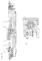
- FIG. 1 An embodiment of a device according to the invention is in Fig. 1 shown.
- the device shown is part of a drill and has a carriage 6, on which a drill drive 8 is provided for driving a DoppelbohrgestCodes displaced.
- a drill drive 8 is provided for driving a DoppelbohrgestCodes displaced.
- On the foot side of the carriage 6 several clamping tongs 60 are provided for screwing and / or breaking and for holding the drill pipe.
- the device has a rod magazine 1 designed as a revolver magazine.
- This rod magazine 1 is rotatably mounted about a rotation axis 2 relative to the carriage 6 and the drill drive 8.
- the rod magazine 1 six receptacles 4, in each of which an outer tube 32 of the drill string and, centrally coaxially thereto, an inner tube 31 of the drill string is receivable.
- the receptacles 4 are arranged side by side along the circumference of the linkage magazine 1. They lie on a circle 80, the center of which lies on the axis of rotation 2 of the linkage magazine 1.
- the rod magazine 1 has a central axle tube 12, on which the individual receptacles 4 are fixed in a star shape.
- This axle tube 12 is mounted in a trained as a pivot bearing 13, which is provided on a support arm 18 of the carriage 6.
- the receptacles 4 each have a retaining sleeve 42 through which a holding element for the outer tube 32 is formed.
- This retaining sleeve 42 may be formed for example in a sleeve.
- a retaining pin 41 is arranged, which projects from the bottom 44 of the retaining sleeve 42.
- This holding mandrel 41 forms a holding element for the inner tube 31.
- Holding mandrel 41 and holding bushing 42 are arranged coaxially.
- the retaining pin 41 has an annular stop 45 which is offset from the bottom 44 of the retaining sleeve 42 in the direction of the male pipe 31, ie towards the mandrel tip and bushing opening.
- the inner tube 31 is thus held offset relative to the outer tube 32 and protrudes from this on the side facing away from the receptacle 4.
- a manipulator 20 is provided for moving the tubes 31, 32 between the boom magazine 1 and the drilling axis 9 extending along the carriage 6.
- This manipulator 20 is designed as a three-axis manipulator with three orthogonal linear axes of movement.
- the manipulator 20 has a manipulator arm 24 which in the longitudinal direction the carriage 6, parallel to the drilling axis 9, is movable.
- a rail 25 is provided on the carriage 6 via retaining arms, on which the manipulator arm 24 is displaceably mounted by means of a longitudinal guide, in particular a sliding guide.
- a drive device not shown, is provided.
- the manipulator 20 has two telescopic arms 27, 28.
- the telescopic arm 27 is telescopically transversely to the longitudinal direction of the carriage 6, the second telescopic arm 28 in the direction perpendicular to the two aforementioned directions.
- the L-shaped telescopic arms 27, 28 are arranged so that they surround the rod magazine 1.
- the second telescopic arm 28 extends beyond the rod magazine 1 from the first telescopic arm 27.
- the two telescopic arms 27, 28 each have at least one hydraulic cylinder.
- a yoke 29 is provided, which runs parallel to the drilling axis 9 and the longitudinal direction of the carriage 6. At the two opposite ends of this yoke 29 a respective gripper 21, 22 for gripping the tubes 31, 32 is provided.
- FIGS. 1 and 6 to 8 Individual procedural steps in assembling the collated drill string are in the FIGS. 1 and 6 to 8 shown. As shown in these figures, inner tube 31 and outer tube 32 are bored together, ie in pairs, in the drilling axis 9 during drilling.
- Fig. 1 As in Fig. 1 is shown, at the beginning of the removal process, the gripper tongs 21, 22 moved by moving the manipulator 20 to the pair of tubes to be removed and the gripper tongs 21, 22 closed.
- the first gripper 21 engages an inner tube 31, the second gripper tongs 22 a surrounding outer tube 32.
- the manipulator 20 along the carriage 6 from Lafettenfuß away on the drill drive 8 to move and the pair of tubes consisting of outer tube 32 and inner tube 31 is thereby pulled out of the receptacle 4.
- the pair of tubes is then lifted radially out of the rod magazine 1.
- the second telescopic arm 28 is extended and arranged the pair of tubes above the drilling axis 9. Subsequently, the manipulator 20 together with the gripped tube pair along the carriage 6 is driven away from the drill drive 8 to the carriage foot.
- the first telescopic arm 27 is retracted and thereby lowered the pipe pair in the drilling axis 9.
- the drill drive 8 moved along the carriage 6 to the pair of tubes.
- the inner tube 31 is connected to the drill drive 8 and then the first gripper 21 open.
- the outer tube 32 is connected to the drill drive 8 and the second gripper tongs 22 are opened.
- the pipe pair can be connected to an adjacent, already sunken pipe pair 38.
- the rod magazine 1 is rotated so that a filled receptacle 4 reaches the top-side removal position and the removal operation described is started again.
- an inner tube 31 is pulled axially out of the surrounding outer tube 32, detached from the remaining inner tube linkage and gripped by means of both gripping tongs 21, 22 of the manipulator 20 ( FIG. 9 ). If necessary, the outer tube 32 can be held by means of the clamping tongs 60.
- the inner tube 31 is arranged frontally in front of an empty receptacle 4 of the linkage magazine 1.
- the drill drive 8 is connected to the outer rod and an outer tube 32 is pulled by axial movement of the drill drive 8 and released from the adjacent outer tube.
- the outer tube 32 is gripped by both gripping tongs 21, 22 of the manipulator 20 and separated from the drill drive 8.
- the manipulator 20 is corresponding Figures 11 and 12 such a procedure that the outer tube. 32 at the front is arranged in front of an already occupied with an inner tube 31 receptacle 4.
- the outer tube 32 is moved over the inner tube 31 into the receptacle 4.
- the two grippers 21, 22, which hold the outer tube 32, can now be opened.
- the process can now be repeated to pull another outer tube 32 until the entire outer rod 32 is magazined.
- the inner tube 31 may also have a spiral screw.
- the clamping shells 23 of the two grippers 21, 22 suitably have a width which is greater than the pitch of the screw helix.
- FIGS. 13 and 14 show how the rod magazine 1 of the device Fig. 1 can be replaceable provided.
- the bearing 13 has two bearing shells 14, 14 ', wherein the first bearing shell 14 relative to the second bearing shell 14' is pivotable. As a result, the bearing can be opened and the axle tube 12 removed.
- a plug connection with a sleeve 51 is provided on the rear side of the axle tube 12. From this sleeve 51, the axle tube 12 can be pulled axially forward, after the axle tube 12 is released by loosening the front bearing 13.
- a front part of the linkage magazine 1, which contains the receptacles 4 and thus can also be referred to as a receiving part 71, can in this case by a rearward drive part 72 of the rod magazine 1 are solved.
- a cover 53 is provided on the rod magazine 1 on the front side facing away from the receptacles 4, which limits an axial movement of the tubes and in particular prevents slipping out of the receptacles 4.
- the sleeve 51 may be formed for a positive connection with the axle tube 12.
- eyelets 56 are provided with which this can be gebolzt to secure against unintentional release and / or torque transmission to the drive member 72.
Landscapes
- Engineering & Computer Science (AREA)
- Geology (AREA)
- Life Sciences & Earth Sciences (AREA)
- Mining & Mineral Resources (AREA)
- Physics & Mathematics (AREA)
- Environmental & Geological Engineering (AREA)
- Fluid Mechanics (AREA)
- Mechanical Engineering (AREA)
- General Life Sciences & Earth Sciences (AREA)
- Geochemistry & Mineralogy (AREA)
- Earth Drilling (AREA)
- Perforating, Stamping-Out Or Severing By Means Other Than Cutting (AREA)
- Drilling And Boring (AREA)
Abstract
Description
Die Erfindung betrifft ein Bohrgerät, insbesondere ein Erd- oder Gesteinsbohrgerät, gemäß dem Oberbegriff des Anspruchs 1. Ein solches Bohrgerät weist unter anderem eine Vorrichtung zum Beschicken einer Bohreinrichtung des Bohrgerätes mit einem Doppelgestänge auf, mit einem Gestängemagazin, das mehrere Aufnahmen für Innenrohre und Außenrohre des Doppelgestänges aufweist. Die Erfindung ist dabei unter anderem durch einen Manipulator zum Greifen und Verfahren der Rohre in das und aus dem Gestängemagazin gekennzeichnet.The invention relates to a drilling rig, in particular a burial or rock drilling apparatus, according to the preamble of
Ein gattungsgemäßes Bohrgerät ist aus der
Eine weitere Vorrichtung zum Beschicken eines Bohrgerätes mit einem Bohrgestänge ist beispielsweise aus der
Eine weitere Vorrichtung mit einem feststehenden, teilzylindrischen Magazin und einem um die Zylinderachse schwenkbaren Greifer ist aus der
Die
Ein weiteres schwenkbares Magazin geht aus der
Aus der
Auch aus der
Die
Weitere Kastenmagazine sind aus der
Die
Aufgabe der Erfindung ist es ein Bohrgerät, insbesondere ein Erd- oder Gesteinsbohrgerät, mit einer Vorrichtung zum Beschicken einer Bohreinrichtung des Bohrgerätes mit einem Doppelgestänge anzugeben, das bei kompaktem und einfachem Aufbau der Vorrichtung eine besonders hohe Zuverlässigkeit und Betriebssicherheit gewährleistet. The object of the invention is to provide a drill, in particular an earth or rock drill, with a device for feeding a drilling device of the drill with a double rod, which ensures a particularly high reliability and reliability in a compact and simple design of the device.
Die Aufgabe wird erfindungsgemäß durch ein Bohrgerät mit den Merkmalen des Anspruchs 1 gelöst. Bevorzugte Ausführungsbeispiele sind in den abhängigen Ansprüchen angegeben.The object is achieved by a drill with the features of
Bei der Vorrichtung zum Beschicken des erfindungsgemäßen Bohrgerätes ist vorgesehen, dass das Gestängemagazin als ein drehbares Revolvermagazin mit Doppelaufnahmen ausgebildet ist, welche jeweils ein Halteelement für ein Außenrohr und ein weiteres Halteelement für ein innerhalb des Außenrohres angeordnetes Innenrohr aufweisen.In the device for feeding the drilling device according to the invention it is provided that the rod magazine as a rotatable Revolver magazine is formed with double receptacles, which each have a holding element for an outer tube and a further holding element for an inner tube arranged within the outer tube.
Ein Grundgedanke der Erfindung kann in einer Ausbildung eines Revolvermagazins mit Doppelaufnahmen gesehen werden, die jeweils eine Lagerung eines Rohrpaares bestehend aus einem Innenrohr und einem Außenrohr am selben Platz zulassen. Erfindungsgemäß können die Innenrohre und die Außenrohre in einer ineinander gesteckten Position im Magazin gehalten werden. Die Rohre können somit in genau der Anordnung magaziniert werden, in der sie sich auch beim Doppelrohrbohren befinden. Hierdurch wird die Zahl der bei der Beschickung der Bohreinrichtung oder beim Magazinieren erforderlichen Umgreifprozesse reduziert, was einen besonders zuverlässigen Betrieb, insbesondere eine besonders einfache Manipulatorsteuerung, bei einfachem apparativem Aufbau gewährleistet. Die Betriebssicherheit, insbesondere bei der Manipulatorhandhabung, wird weiter dadurch verbessert, dass die Doppelaufnahmen nicht ortsfest sondern an einem drehbaren Revolvermagazin vorgesehen sind. Dieses Revolvermagazin ermöglicht es, die in der Bohranordnung befindlichen magazinierten Doppelgestängeschüsse stets an die selbe Übergabeposition zu verbringen, an der sie von einem Bediener gut gesehen sowie in besonders zuverlässiger Weise vom Manipulator gegriffen und in die Bohrachse verbracht werden können.A basic idea of the invention can be seen in a design of a revolver magazine with double receptacles, which each allow a bearing of a tube pair consisting of an inner tube and an outer tube in the same place. According to the invention, the inner tubes and the outer tubes can be held in a nested position in the magazine. The tubes can thus be magazined in exactly the arrangement in which they are also in the double-tube drilling. As a result, the number of Umgreifprozesse required during the loading of the drilling device or magazining is reduced, which ensures a particularly reliable operation, in particular a particularly simple manipulator control, with a simple apparatus design. The reliability, especially in manipulator handling, is further improved by the fact that the double shots are not stationary but are provided on a rotatable turret magazine. This revolver magazine makes it possible to always spend the magazinierten Doppelgestängeschüsse located in the drilling at the same transfer position where they can be well seen by an operator and used in a particularly reliable manner by the manipulator and spent in the drilling axis.
Unter einem Revolvermagazin kann insbesondere ein Magazin verstanden werden, bei dem die Aufnahmen und/oder die aufgenommenen Rohre um die Drehachse des Magazins herum angeordnet sind, wobei die Längsachsen der aufgenommenen Rohre geeigneter Weise parallel zur Drehachse verlaufen. Für einen besonders einfachen Antrieb des Magazins verläuft die Drehachse vorzugsweise mittig bezüglich der Aufnahmen, insbesondere entlang einer Mittenachse des Gestängemagazins.A revolver magazine may in particular be understood to mean a magazine in which the receptacles and / or the tubes received are arranged around the axis of rotation of the magazine, the longitudinal axes of the tubes received being suitably parallel to the axis of rotation. For a particularly simple drive of the magazine, the axis of rotation preferably runs centrally with respect to the receptacles, in particular along a center axis of the rod magazine.
Vorzugsweise sind die Aufnahmen auf einem Kreis angeordnet, dessen Mittelpunkt geeigneter Weise auf der Drehachse des Gestängemagazins liegt. Die Längsachsen der Rohre und der Aufnahmen können auf einem Zylindermantel liegen, dessen Längsachse mit der Drehachse zusammenfällt. Eine solche Anordnung als Trommelmagazin ist besonders kompakt.Preferably, the receptacles are arranged on a circle whose center is suitably on the axis of rotation of the rod magazine. The longitudinal axes of the tubes and the receptacles may lie on a cylinder jacket whose longitudinal axis coincides with the axis of rotation. Such an arrangement as a drum magazine is particularly compact.
Eine konstruktiv besonders einfache Vorrichtung ist dadurch gegeben, dass das Gestängemagazin ein zentrales Achsrohr aufweist, über welches das Gestängemagazin an zumindest einer Lagerstelle gelagert ist. Vorzugsweise ist die Lagerung über das zentrale Achsrohr zumindest auf der den Aufnahmen abgewandten Stirnseite des Gestängemagazins vorgesehen. Diese Art der Lagerung ermöglicht einen besonders einfachen Zugriff auf die magazinierten Rohre. Das Gestängemagazin kann auch mehrfach am zentralen Achsrohr gelagert sein, wobei das zentrale Achsrohr grundsätzlich auch unterbrochen sein kann. Besonders vorteilhaft ist nach der Erfindung, dass das Gestängemagazin auswechselbar in der Vorrichtung gelagert ist. Die Auswechselbarkeit des Magazins ermöglicht es, die Vorrichtung schnell und einfach auf ein anderes Gestängesystem umzurüsten.A structurally particularly simple device is given by the fact that the rod magazine has a central axle tube, via which the rod magazine on at least one bearing point is stored. Preferably, the storage is provided via the central axle tube at least on the side facing away from the receptacles end side of the rod magazine. This type of storage allows particularly easy access to the magazine tubes. The linkage magazine can also be mounted several times on the central axle tube, wherein the central axle tube can in principle also be interrupted. It is particularly advantageous according to the invention that the rod magazine is interchangeable stored in the device. The interchangeability of the magazine makes it possible to quickly and easily convert the device to another linkage system.
Vorteilhaft ist hierfür, dass zumindest eine Lagerstelle des Gestängemagazins lösbar ist. Durch lösbare Lagerstellen kann in besonders einfacher Weise ein auswechselbares Magazin geschaffen werden. Die lösbare Lagerstelle kann beispielsweise zwei oder mehr Lagerschalen aufweisen, die voneinander lösbar und wieder verschließbar sind. Insbesondere kann eine Lagerschale gegenüber einer anderen Lagerschale verschwenkbar vorgesehen werden. Hierdurch kann beispielsweise eine aufklappbare Lagerstelle geschaffen werden. Die Lagerstellen umfassen geeigneter Weise Gleit- oder Wälzlager.It is advantageous for this that at least one bearing point of the linkage magazine is detachable. By releasable bearings, a replaceable magazine can be created in a particularly simple manner. The detachable bearing point can, for example, have two or more bearing shells, which can be detached from one another and closed again. In particular, a bearing shell can be provided pivotably with respect to another bearing shell. As a result, for example, a hinged bearing point can be created. The bearings suitably include plain or roller bearings.
Ferner ist nach der Erfindung vorteilhaft, dass das Gestängemagazin mehrteilig mit einem Aufnahmeteil, an dem die Aufnahmen angeordnet sind, und einem Antriebsteil, an dem ein Magazindrehantrieb vorgesehen ist, ausgebildet ist, wobei das Aufnahmeteil insbesondere lösbar am Antriebsteil befestigt ist. Hierdurch kann ein teilbares Magazin geschaffen werden, bei dem die Aufnahmen inklusive der darin gelagerten Rohre vom Antriebsteil des Magazins abgenommen werden können und somit eine besonders gute Handhabbarkeit gegeben ist. Vorzugsweise sind das Aufnahmeteil und das Antriebsteil über eine Steckverbindung verbunden, die durch Axialbewegung in Richtung der Magazindrehachse und/oder der Längsachse der aufgenommenen Bohrrohre lösbar ist. Insbesondere kann eine Steckverbindung am zentralen Achsrohr vorgesehen sein. Um eine Kraftübertragung zwischen Antriebsteil und aufgestecktem Aufnahmeteil zu erreichen, ist die Steckverbindung geeigneter Weise drehfest, insbesondere als Formschlussverbindung, ausgebildet.Furthermore, it is advantageous according to the invention that the rod magazine is in several parts with a receiving part on which the receptacles are arranged, and a drive part, on which a magazine rotary drive is provided, is formed, wherein the receiving part is in particular releasably secured to the drive part. In this way, a divisible magazine can be created, in which the recordings including the tubes mounted therein can be removed from the drive part of the magazine and thus a particularly good handling is given. Preferably, the receiving part and the drive part are connected via a plug connection, which is releasable by axial movement in the direction of the magazine rotation axis and / or the longitudinal axis of the recorded drill pipes. In particular, a plug connection can be provided on the central axle tube. In order to achieve a power transmission between the drive part and attached receiving part, the connector is suitably rotatable, in particular as a positive connection formed.
Für einen besonders sicheren Transport des entnommenen Gestängemagazins ist es vorteilhaft, dass ein Sicherungsdeckel vorgesehen ist, der geeigneter Weise stirnseitig auf das Gestängemagazin, insbesondere das Aufnahmeteil, aufsetzbar und arretierbar ist. Hierdurch kann das Gestängemagazin inklusive der magazinierten Innenrohre und der Außenrohre besonders sicher gehandhabt werden. Der Sicherungsdeckel wird bevorzugt an der den Aufnahmen abgewandten Stirnseite des Trommelmagazins vorgesehen.For a particularly safe transport of the removed rod magazine, it is advantageous that a safety cover is provided, which is suitably frontally on the rod magazine, in particular the receiving part, placed and locked. As a result, the rod magazine including the magazine inner tubes and the outer tubes can be handled very safe. The securing cover is preferably provided on the side facing away from the receptacles end face of the drum magazine.
Nach der Erfindung ist eine Lafette vorgesehen, die zum Führen eines Bohrantriebes des Doppelgestänges dient. Der Bohrantrieb kann ein einzelner Antrieb zum gleichzeitigen Antreiben beider Gestänge sein oder aus zwei separaten Antrieben bestehen, wobei der oder die Antriebe sowohl drehend als auch drehschlagend ausgebildet sein können. Die Handhabung der erfindungsgemäßen Vorrichtung wird dadurch erleichtert, dass die Drehachse des Revolvermagazins und/oder die Längsachsen der Aufnahmen zumindest annähernd parallel zur Lafette und/oder zu einer hieran verlaufenden Bohrachse angeordnet sind. Die Übergabeposition am Revolvermagazin befindet sich vorzugsweise auf gleicher Höhe wie die Bohrachse. In diesem Fall ist bei der Entnahme der Rohre aus dem Magazin nur eine Translationsbewegung erforderlich. Eine besonders kompakte Vorrichtung wird dadurch erhalten, dass das Gestängemagazin an der Lafette gelagert ist. Eine besonders einfache Bauform ist dadurch gegeben, dass zumindest ein Haltearm vorgesehen ist, an der das Gestängemagazin, insbesondere am zentralen Achsrohr, an der Lafette gelagert ist.According to the invention, a carriage is provided, which serves to guide a drill drive of the double rod. The drill drive may be a single drive for simultaneously driving both linkages or consist of two separate drives, wherein the one or more drives can be designed both rotationally and rotationally. The handling of the device according to the invention is facilitated by the fact that the axis of rotation of the revolving magazine and / or the longitudinal axes of the receptacles are arranged at least approximately parallel to the carriage and / or to a drilling axis extending thereon. The transfer position on the revolver magazine is preferably at the same height as the drilling axis. In this case, only one translational movement is required when removing the tubes from the magazine. A particularly compact device is obtained in that the rod magazine is mounted on the carriage. A particularly simple design is given by the fact that at least one holding arm is provided, on which the linkage magazine, in particular on the central axle tube, is mounted on the carriage.
Die Aufnahmen sind geeigneter Weise als Einschubhalterungen ausgebildet, welche die Rohre bei axialer Verschiebung freigeben. Beispielsweise kann das Halteelement für das Innenrohr einen Haltedorn aufweisen, auf den das Innenrohr aufgesteckt wird. Das Halteelement für das Außenrohr kann beispielsweise eine Aufnahmebuchse und/oder ebenfalls einen Aufnahmedorn aufweisen. Geeigneter Weise sind die beiden Halteelemente einer Doppelaufnahme für eine koaxiale Halterung des Außenrohres und des Innenrohres vorgesehen. Insbesondere wenn die Aufnahmen Buchsen zur Halterung der Rohre aufweisen, können diese auch als Köcher bezeichnet werden.The recordings are suitably designed as slide-in holders, which release the tubes during axial displacement. For example, the holding element for the inner tube may have a retaining pin, on which the inner tube is plugged. The holding element for the outer tube may, for example, have a receiving bush and / or likewise a receiving mandrel. Suitably, the two holding elements of a double receptacle for a coaxial mounting of the outer tube and the inner tube are provided. In particular, if the recordings have sockets for holding the tubes, they can also be referred to as quivers.
Vorzugsweise werden die Innenrohre so im Gestängemagazin gelagert, dass sie ein Stück aus dem umgebenden Außenrohr hervorstehen. Es ist dann bei einfacher Manipulatorausführung möglich, beide Rohre gemeinsam aus dem Magazin zu entnehmen. Sofern die Innenrohre gleich lang oder kürzer als die Außenrohre sind, kann hierfür vorgesehen sein, die Halteelemente für die Innenrohre mit einem Axialversatz gegenüber den Halteelementen für die Außenrohre auszubilden. Vorzugsweise weisen die Halteelemente einen ersten Anschlag für das Innenrohr und einen zweiten Anschlag für das Außenrohr auf, wobei die Anschläge axial gegeneinander versetzt sind. Vorzugsweise ist der Anschlag für das Innenrohr in Richtung auf das aufzunehmende Rohr und/oder ins Magazininnere hin versetzt.Preferably, the inner tubes are stored in the rod magazine so that they protrude a piece of the surrounding outer tube. It is then possible with simple manipulator design to remove both tubes together from the magazine. If the inner tubes are the same length or shorter than the outer tubes, this can be provided to form the holding elements for the inner tubes with an axial offset relative to the holding elements for the outer tubes. Preferably, the holding elements have a first stop for the inner tube and a second stop for the outer tube, wherein the stops are axially offset from each other. Preferably, the stop for the inner tube is offset in the direction of the male tube and / or inside the magazine.
Vorteilhafter Weise weist der Manipulator drei Bewegungsachsen auf, von denen eine etwa parallel zur Drehachse des Revolvermagazins, der Längsachse der Lafette und/oder den Längsachsen der Aufnahmen verläuft. Geeigneter Weise handelt es sich bei den Bewegungsachsen um bevorzugt orthogonale Linearachsen, wodurch besonders kompakte Abmessungen der erfindungsgemäßen Vorrichtung ermöglicht werden. Grundsätzlich kann es sich bei den Bewegungsachsen aber auch um Rotationsachsen handeln. Eine besonders robuste und vielseitige Anordnung ist dadurch gegeben, dass der Manipulator einen Manipulatorarm aufweist, der auf einer Längsführung verschiebbar ist. Die Längsführung ist geeigneter Weise an der Lafette vorgesehen oder Teil dieser Lafette. Der Manipulatorarm ist vorzugsweise teleskopierbar, insbesondere in insgesamt zwei Bewegungsrichtungen doppelt teleskopierbar ausgebildet.Advantageously, the manipulator has three axes of movement, one of which runs approximately parallel to the axis of rotation of the revolving magazine, the longitudinal axis of the carriage and / or the longitudinal axes of the receptacles. Suitably, the axes of motion are preferably orthogonal linear axes, thereby particularly compact dimensions of the device according to the invention are made possible. In principle, however, the axes of movement can also be rotational axes. A particularly robust and versatile arrangement is given by the fact that the manipulator has a manipulator arm which is displaceable on a longitudinal guide. The longitudinal guide is suitably provided on the carriage or part of this carriage. The manipulator arm is preferably telescopic, in particular in two directions of movement formed double telescopically.
Ein besonders schneller und sicherer Betrieb der erfindungsgemäßen Vorrichtung wird dadurch ermöglicht, dass der Manipulator zumindest zwei Greiferzangen aufweist. Die Greiferzangen sind erfindungsgemäß unabhängig voneinander betätigbar. Vorzugsweise sind die Greiferzangen mit einem Greifbereich ausgebildet, der sowohl den Durchmesser der Innenrohre als auch den Durchmesser der Außenrohre umfasst, so dass jede Greiferzange sowohl Außenrohre als auch Innenrohre greifen kann. Die beiden Greiferzangen sind bevorzugt in einer parallel zur Lafette und/oder zur Bohrachse verlaufenden Achse angeordnet. Geeigneter Weise sind die beiden Greiferzangen über ein Joch verbunden, das bevorzugt endseitig am Manipulator vorgesehen ist. Insbesondere kann vorgesehen werden, beim Entnehmen der Rohre aus dem Gestängemagazin das Innenrohr und das Außenrohr mit getrennten Greiferzangen zu fassen. Beim Einbringen der Rohre in das Gestängemagazin können beide Greiferzangen für dasselbe Rohr verwendet werden.A particularly fast and reliable operation of the device according to the invention is made possible in that the manipulator has at least two gripper tongs. The gripper tongs are actuated independently of each other according to the invention. Preferably, the gripper tongs are formed with a gripping area which comprises both the diameter of the inner tubes and the diameter of the outer tubes, so that each gripper tongs can grip both outer tubes and inner tubes. The two gripper tongs are preferably arranged in an axis running parallel to the carriage and / or to the drilling axis. Suitably, the two grippers are connected via a yoke, which is preferably provided on the end side on the manipulator. In particular, it can be provided to grasp the inner tube and the outer tube with separate gripping tongs when removing the tubes from the rod magazine. When inserting the tubes in the boom magazine both gripper tongs can be used for the same tube.
Vorzugsweise sind nach der Erfindung Mittel vorgesehen, mit denen das Gestängemagazin stufenlos positioniert und/oder arretiert werden kann. Dies erlaubt es, die Winkellagen der Aufnahmen, insbesondere die Entnahme- und/oder Beladeposition, stufenlos zu positionieren und zu arretieren.Preferably, according to the invention means are provided with which the rod magazine can be continuously positioned and / or locked. This allows the angular positions of the recordings, in particular the removal and / or loading position, to be infinitely positioned and locked.
Die Innenrohre können beispielsweise glatt oder als Schneckenbohrrohre ausgebildet sein. Sofern Schneckenbohrrohre verwendet werden, ist es vorteilhaft, wenn die Greiferzangen Klemmschalen aufweisen, die breiter als das Maß einer Wendelsteigung sind. Hierdurch kann ein sicherer Greifvorgang gewährleistet werden.The inner tubes may for example be smooth or formed as auger tubes. If auger tubes are used, it is advantageous if the gripper tongs have clamping shells that are wider than the extent of a helical pitch. As a result, a secure gripping operation can be ensured.
Die vorausgehend beschriebene Beschickungsvorrichtung ist erfindungsgemäß an einem Bohrgerät mit einer Bohreinrichtung vorgesehen, welche einen Bohrantrieb zum Doppelrohrbohren aufweist. Derartige Bohrgeräte können in bekannter Weise mit einem Fahrgestell, verschiedenen Aggregaten sowie einer Bedieneinheit ausgerüstet sein. Die Bohreinrichtung kann über einen Verstellmechanismus über dem Fahrgestell in nahezu jede beliebige Position gebracht werden.The charging device described above is inventively provided on a drill with a drilling device having a drill drive for double pipe drilling. Such drills can be equipped in a known manner with a chassis, various units and a control unit. The drilling device can be brought via an adjusting mechanism on the chassis in almost any position.
Erfindungsgemäß ist vorgesehen, dass der Bohrantrieb auf einer Lafette gelagert ist. Das erfindungsgemäße Bohrgerät ist unter anderem dadurch gekennzeichnet, dass das Gestängemagazin zwischen der Lafette und einem ersten Teleskoparm des Manipulators angeordnet ist und dass an den ersten Teleskoparm ein zweiter Teleskoparm mit den Greiferzangen verschiebbar gelagert ist. Der Manipulator und das Revolvermagazin können somit auf einer Seite der Lafette angeordnet werden, so dass auf der gegenüberliegenden Seite der Lafette für einen Bediener ein freier Zugang zum Bohrantrieb und dem Bohrstrang gegeben ist. Der Manipulator ist vorzugsweise unterhalb des Revolvermagazins an der Lafette befestigt. Der etwa C-förmig ausgebildete Manipulator umgreift' somit das Revolvermagazin, was zu einer besonders kompakten Anordnung führt.According to the invention it is provided that the drill drive is mounted on a carriage. The drill according to the invention is inter alia characterized in that the linkage magazine between the carriage and a first telescopic arm of the manipulator is arranged and that on the first telescopic arm, a second telescopic arm is slidably mounted with the gripper tongs. The manipulator and the revolver magazine can thus be arranged on one side of the carriage, so that on the opposite side of the carriage for an operator free access to the drill drive and the drill string is given. The manipulator is preferably mounted below the revolver magazine on the carriage. The approximately C-shaped manipulator 'thus surrounds the revolving magazine, resulting in a particularly compact arrangement.
Grundsätzlich kann das erfindungsgemäße Gestängemagazin statt mit einem Doppelgestänge auch mit einem Einfachgestänge bestückt werden. Die Auswechselbarkeit des Gestängemagazins kann als unabhängiger Erfindungsaspekt angesehen werden.Basically, the rod magazine according to the invention can be equipped with a single rod instead of a double rod become. The interchangeability of the linkage magazine can be regarded as an independent invention aspect.
Bei einem Verfahren kann vorgesehen sein, dass auf einer Doppelaufnahme ineinander angeordnete Rohre gemeinsam aus dem Gestängemagazin entnommen und in eine Bohrachse verbracht werden und/oder dass beim Magazinieren des Doppelgestänges zunächst die Innenrohre und anschließend die Außenrohre des Doppelgestänges im Gestängemagazin gelagert werden. Vorzugsweise wird zunächst das Innengestänge vollständig magaziniert und dann mit dem Magazinieren des Außengestänges begonnen.In one method, provision may be made for tubes, which are arranged one inside the other, to be taken out of the rod magazine together and placed in a drilling axis and / or that the inner tubes and then the outer tubes of the double rod are first stored in the rod magazine when the double rod is being magazineed. Preferably, first the inner rod is completely magazined and then started with the magazining of the outer rod.
Die Erfindung wird nachfolgend anhand bevorzugter Ausführungsbeispiele näher erläutert, die schematisch in den Figuren dargestellt sind. In den Figuren zeigen:
- Fig. 1
- Eine Seitenansicht (a) und eine Querschnittsansicht (b) einer erfindungsgemäßen Vorrichtung zur Durchführung des beschriebenen Verfahrens gemäß einer ersten Ausführungsform;
- Fig. 2
- Eine teilweise geschnittene Detailansicht des Manipulators aus
Fig. 1 von der Seite; - Fig. 3
- eine Querschnittsansicht der Vorrichtung aus
Fig. 1 mit teilweise geschnittenem Manipulator bei anderem Betriebszustand des Manipulators; - Fig. 4
- eine teilweise geschnittene Detailansicht einer Doppelaufnahme des Gestängemagazins aus
Fig. 1 mit einem glatten Innenrohr; - Fig. 5
- eine teilweise geschnittene Detailansicht einer Doppelaufnahme des Gestängemagazins aus
Fig. 1 mit einem wendelbelegten Innenrohr; - Fig. 6
bis 8 - die Vorrichtung aus
Fig. 1 beim Zusammenfügen eines magazinierten Bohrgestänges in der Bohrachse entsprechend dem beschriebenen Verfahren in Seitenansicht (a) und Querschnittsansicht (b); - Fig. 9
bis 12 - die Vorrichtung aus
Fig. 1 beim Magazinieren des Bohrgestänges entsprechend dem erfindungsgemäßen Verfahren in Seitenansicht (a) und Querschnittsansicht (b); - Fig. 13
- die Vorrichtung aus
Fig. 1 bei aufgeklappter Magazinlagerung; und - Fig. 14
- die Vorrichtung aus
Fig. 1 bei geteiltem Magazin.
- Fig. 1
- A side view (a) and a cross-sectional view (b) of a device according to the invention for carrying out the described method according to a first embodiment;
- Fig. 2
- A partially cut detail view of the manipulator
Fig. 1 of the page; - Fig. 3
- a cross-sectional view of the device
Fig. 1 with partially cut manipulator in other operating condition of the manipulator; - Fig. 4
- a partially cut detail of a double recording of the rod magazine
Fig. 1 with a smooth inner tube; - Fig. 5
- a partially cut detail of a double recording of the rod magazine
Fig. 1 with a helical inner tube; - Fig. 6 to 8
- the device off
Fig. 1 when assembling a magazin Bohrgestänges in the drilling axis according to the described method in side view (a) and cross-sectional view (b); - Fig. 9 to 12
- the device off
Fig. 1 during storage of the drill pipe according to the method according to the invention in side view (a) and cross-sectional view (b); - Fig. 13
- the device off
Fig. 1 with unfolded magazine storage; and - Fig. 14
- the device off
Fig. 1 with shared magazine.
Ein Ausführungsbeispiel einer erfindungsgemäßen Vorrichtung ist in
Die Vorrichtung weist ein als Revolvermagazin ausgebildetes Gestängemagazin 1 auf. Dieses Gestängemagazin 1 ist um eine Drehachse 2 relativ zur Lafette 6 und zum Bohrantrieb 8 drehbar gelagert. In der dargestellten Ausführungsform weist das Gestängemagazin 1 sechs Aufnahmen 4 auf, in denen jeweils ein Außenrohr 32 des Bohrgestänges und, mittig koaxial hierzu, ein Innenrohr 31 des Bohrgestänges aufnehmbar ist. Die Aufnahmen 4 sind entlang des Umfangs des Gestängemagazins 1 nebeneinander angeordnet. Sie liegen auf einem Kreis 80, dessen Mittelpunkt auf der Drehachse 2 des Gestängemagazins 1 liegt.The device has a
Zur drehbaren Lagerung weist das Gestängemagazin 1 ein zentrales Achsrohr 12 auf, an dem die einzelnen Aufnahmen 4 sternförmig befestigt sind. Dieses Achsrohr 12 ist in einer als Drehlager ausgebildeten Lagerstelle 13 gelagert, die an einem Haltearm 18 der Lafette 6 vorgesehen ist.For rotatable mounting, the
Die als Doppelaufnahmen ausgebildeten Aufnahmen 4 sind in
Wie in
Der Manipulator 20 weist zwei Teleskoparme 27, 28 auf. Der Teleskoparm 27 ist quer zur Längsrichtung der Lafette 6 teleskopierbar, der zweite Teleskoparm 28 in der zu den beiden zuvor genannten Richtungen senkrechten Richtung. Die L-förmig angeordneten Teleskoparme 27, 28 sind dabei so angeordnet, dass sie das Gestängemagazin 1 umfangen. Insbesondere erstreckt sich der zweite Teleskoparm 28 vom ersten Teleskoparm 27 aus über das Gestängemagazin 1 hinweg. Zum angetriebenen Teleskopieren weisen die beiden Teleskoparme 27, 28 jeweils mindestens einen Hydraulikzylinder auf.The
Endseitig am zweiten Teleskoparm 28 ist ein Joch 29 vorgesehen, welches parallel zur Bohrachse 9 und der Längsrichtung der Lafette 6 verläuft. An den beiden gegenüberliegenden Enden dieses Joches 29 ist je eine Greiferzange 21, 22 zum Greifen der Rohre 31, 32 vorgesehen.At the end on the second
Einzelne Verfahrensschritte beim Zusammenfügen des magazinierten Bohrgestänges sind in den
Wie in
Gemäß
Nun wird der erste Teleskoparm 27 wieder eingefahren und dabei das Rohrpaar in die Bohrachse 9 abgesenkt. Anschließend wird, wie in
Zum Einfügen eines weiteren Rohrpaares wird das Gestängemagazin 1 so weitergedreht, dass eine gefüllte Aufnahme 4 in die oberseitige Entnahmeposition gelangt und der beschriebene Entnahmevorgang wird von neuem gestartet.To insert a further tube pair, the
Der Rückgewinn und die Magazinierung des Gestänges sind in
Zunächst wird mittels des Bohrantriebes 8 ein Innenrohr 31 axial aus dem umgebenden Außenrohr 32 herausgezogen, vom restlichen Innenrohrgestänge gelöst und mittels beider Greifzangen 21, 22 des Manipulators 20 gegriffen (
Durch anschließendes Betätigen des Manipulators 20 in allen drei Achsrichtungen, wird das Innenrohr 31 stirnseitig vor einer leeren Aufnahme 4 des Gestängemagazins 1 angeordnet.By subsequently actuating the
Durch anschließendes Verfahren des Manipulators 20 in Längsrichtung der Lafette 6 auf den Lafettenfuß zu wird das Innenrohr 31 in die Aufnahme 4 eingeschoben. Die beiden Greiferzangen 21, 22 können nun geöffnet werden.
Anschließend wird der Bohrantrieb 8 an das nächste Innenrohr 31 herangefahren und dieses durch Zurückziehen des Bohrantriebs 8 aus dem umgebenden Außenrohr 32 herausgezogen. Durch Wiederholung der beschriebenen Schritte kann das gesamte Innengestänge aus dem Außengestänge herausgezogen werden und magaziniert werden. Der nach jedem Entnahmeschritt in der Bohrachse 9 verbleibende Innengestängeabschnitt wird mittels der Klemmzangen 60 gehalten.By subsequent movement of the
Subsequently, the
Ist das Innengestänge vollständig gezogen, wird der Bohrantrieb 8 mit dem Außengestänge verbunden und ein Außenrohr 32 wird durch axiales Verfahren des Bohrantriebes 8 gezogen und vom benachbarten Außenrohr gelöst.If the inner rod is completely pulled, the
Gemäß
Durch abschließendes Verschieben des Manipulators 20 längs der Lafette 6 wird das Außenrohr 32 über das Innenrohr 31 in die Aufnahme 4 gefahren. Die beiden Greiferzangen 21, 22, die das Außenrohr 32 halten, können nun geöffnet werden. Der Vorgang kann nun zum Ziehen eines weiteren Außenrohres 32 so lange wiederholt werden, bis das gesamte Außengestänge 32 magaziniert ist.By finally moving the
Wie in
Die
In diesem Fall ist die Lagerstelle 13, an der das Achsrohr 12 des Gestängemagazins 1 drehbar gelagert ist, lösbar ausgeführt. Insbesondere weist die Lagerstelle 13 zwei Lagerschalen 14, 14' auf, wobei die erste Lagerschale 14 gegenüber der zweiten Lagerschale 14' verschwenkbar ist. Hierdurch kann das Lager geöffnet und das Achsrohr 12 entnommen werden.In this case, the
Wie
Im Antriebsteil 72, das nach Entnahme des Aufnahmeteils 71 an der Lafette 6 zurückbleibt, befindet sich der Drehantrieb des Gestängemagazins 1. Zum Übertragen der Antriebsenergie vom Antriebsteil 72 an das Aufnahmeteil 71 kann die Hülse 51 für eine Formschlussverbindung mit dem Achsrohr 12 ausgebildet sein.In the
An dem Aufnahmeteil 71 sind Ösen 56 vorgesehen, mit denen dieses zum Sichern gegen ein unbeabsichtigtes Lösen und/oder zur Drehmomentübertragung am Antriebsteil 72 angebolzt werden kann.On the receiving part 71
Claims (8)
- Drilling device, in particular an earth or rock drilling apparatus , comprising- a drilling equipment having a drilling drive (8) for double rod drilling, the drilling drive (8) is supported on a carriage (6) and- a device for charging the drilling equipment with a double rod,- the device for charging the drilling equipment has a rod magazine (1) having several receiving spaces (4) for inner tubes (31) and outer tubes (32) of the double rod, and being designed as a rotatable revolver magazine comprising double receiving spaces, which each have a retaining element for an outer tube (32) and a further retaining element for an inner tube (31) arranged inside the outer tube (32),characterized in that- the device for charging the drilling equipment has a manipulator (20) for gripping and moving the tubes (31, 32) into and out of the rod magazine (1),- the rod magazine (1) is arranged between the carriage (6) and a first telescopic arm (27) of the manipulator (20), and- on the first telescopic arm (27) a second telescopic arm (28) with gripping claws (21, 22) is arranged in a displaceable manner.
- Drilling device according to claim 1,
characterized in that
the receiving spaces (4) are arranged on a circle (80), whose centre lies on an axis of rotation (2) of the rod magazine (1). - Drilling device according to any one of claims 1 or 2,
characterized in that
the rod magazine (1) has a central axle tube (12), by which the rod magazine (1) is supported on at least one bearing point (13). - Drilling device according to any one of claims 1 to 3,
characterized in that
at least one bearing point (13) of the rod magazine (1) is detachable. - Drilling device according to any one of claims 1 to 4,
characterized in that
the rod magazine (1) is designed of several parts comprising a receiving part (71), on which the receiving spaces (4) are arranged, and a drive part (72), on which a rotary magazine drive is arranged, the receiving part (71) being preferably provided in a detachable manner on the drive part (72). - Drilling device according to any one of claims 1 to 5,
characterized in that
the retaining elements have a first stop for the inner tube (31) and a second stop for the outer tube (32), the stops being offset axially with respect to each other. - Drilling device according to any one of claims 1 to 6,
characterized in that
the manipulator (20) has three axes of motion, in particular orthogonal linear axes, one of which extends approximately parallel to the longitudinal axis of the receiving spaces (4). - Drilling device according to any one of claims 1 to 7,
characterized in that
the manipulator (20) has two gripping claws (21, 22).
Priority Applications (5)
| Application Number | Priority Date | Filing Date | Title |
|---|---|---|---|
| ES06004639T ES2309848T3 (en) | 2006-03-07 | 2006-03-07 | DEVICE FOR LOADING A DRILLING EQUIPMENT AND A DRILLING DEVICE. |
| EP06004639A EP1832710B1 (en) | 2006-03-07 | 2006-03-07 | Device for loading a drilling installation and drilling apparatus |
| AT06004639T ATE402322T1 (en) | 2006-03-07 | 2006-03-07 | DEVICE FOR FEEDING A DRILLING EQUIPMENT AND DRILLING UNIT |
| DE502006001190T DE502006001190D1 (en) | 2006-03-07 | 2006-03-07 | Device for loading a drilling device and drill |
| US11/681,968 US7735580B2 (en) | 2006-03-07 | 2007-03-05 | Device for charging a drilling device and drilling apparatus |
Applications Claiming Priority (1)
| Application Number | Priority Date | Filing Date | Title |
|---|---|---|---|
| EP06004639A EP1832710B1 (en) | 2006-03-07 | 2006-03-07 | Device for loading a drilling installation and drilling apparatus |
Publications (2)
| Publication Number | Publication Date |
|---|---|
| EP1832710A1 EP1832710A1 (en) | 2007-09-12 |
| EP1832710B1 true EP1832710B1 (en) | 2008-07-23 |
Family
ID=36764262
Family Applications (1)
| Application Number | Title | Priority Date | Filing Date |
|---|---|---|---|
| EP06004639A Not-in-force EP1832710B1 (en) | 2006-03-07 | 2006-03-07 | Device for loading a drilling installation and drilling apparatus |
Country Status (5)
| Country | Link |
|---|---|
| US (1) | US7735580B2 (en) |
| EP (1) | EP1832710B1 (en) |
| AT (1) | ATE402322T1 (en) |
| DE (1) | DE502006001190D1 (en) |
| ES (1) | ES2309848T3 (en) |
Cited By (2)
| Publication number | Priority date | Publication date | Assignee | Title |
|---|---|---|---|---|
| EP2851504A1 (en) | 2013-09-18 | 2015-03-25 | Klemm Bohrtechnik GmbH | Drill pipe gripper |
| EP3141690A1 (en) | 2015-09-11 | 2017-03-15 | Klemm Bohrtechnik GmbH | Drill pipe gripper |
Families Citing this family (9)
| Publication number | Priority date | Publication date | Assignee | Title |
|---|---|---|---|---|
| US20100239404A1 (en) * | 2009-03-23 | 2010-09-23 | Bert Joseph Blanchard | Storage and deployment system |
| US9038733B2 (en) * | 2009-04-29 | 2015-05-26 | Itrec B.V. | Tubulars storage and handling system |
| CN103069096A (en) * | 2010-05-17 | 2013-04-24 | 维米尔制造公司 | Two pipe horizontal directional drilling system |
| GB2572415A (en) * | 2018-03-29 | 2019-10-02 | Laytrix Ltd | Pipe laying apparatus |
| SE543092C2 (en) * | 2018-05-21 | 2020-10-06 | Epiroc Rock Drills Ab | System for drill bit change in a drilling rig, drilling rig comprising such a system, and a method for changing drill bits using such a system |
| JP7116957B2 (en) * | 2018-09-28 | 2022-08-12 | ソイルメックジャパン株式会社 | Combined use of double tube loading machine and drilling machine |
| IT201900003035A1 (en) * | 2019-03-01 | 2020-09-01 | Beretta Alfredo S R L | ARTICULATED SUPPORT OF MAST DEVICE FOR A DRILLING AND RELATIVE DRILLING MACHINE |
| CN110761722B (en) * | 2019-11-20 | 2024-08-20 | 中国地质大学(北京) | Automatic pipe moving and swinging device for drilling tool matched with drilling machine |
| CN112943124B (en) * | 2021-04-08 | 2024-07-19 | 中煤科工集团重庆研究院有限公司 | Auxiliary drill rod feeding device |
Family Cites Families (13)
| Publication number | Priority date | Publication date | Assignee | Title |
|---|---|---|---|---|
| US3734209A (en) | 1971-08-20 | 1973-05-22 | Bucyrus Erie Co | Well drilling rod and casing assembling method |
| US4013178A (en) * | 1975-01-17 | 1977-03-22 | Brown Cicero C | Pipe racker |
| DE3901664A1 (en) | 1989-01-20 | 1990-07-26 | Bauer Spezialtiefbau | METHOD FOR DRAWING EXTERNAL RODS |
| US5215153A (en) | 1991-11-08 | 1993-06-01 | Younes Joseph F | Apparatus for use in driving or withdrawing such earth entering elements as drills and casings |
| SE500747C2 (en) | 1992-04-07 | 1994-08-22 | Nyman Karl Erik | Equipment for handling and storage of drill pipes |
| JP2941194B2 (en) * | 1995-04-27 | 1999-08-25 | ライト工業株式会社 | Rod exchange device |
| DE59711071D1 (en) | 1997-02-25 | 2004-01-15 | Huette & Co Bohrtechnik Gmbh | Device for handling drilling elements |
| DE59704785D1 (en) * | 1997-02-25 | 2001-11-08 | Huette & Co Bohrtechnik Gmbh | Method and apparatus for double-head overlay drilling |
| DE19830447A1 (en) | 1998-07-08 | 2000-01-13 | Johann Haas | Rock drill magazine |
| DE19810707C2 (en) * | 1998-03-12 | 2003-01-23 | Klemm Bohrtechnik Zweigniederl | Device for producing boreholes with single or double rods |
| DE29903909U1 (en) | 1999-03-05 | 1999-10-07 | Hütte & Co Bohrtechnik GmbH, 57462 Olpe | Device for handling drilling elements |
| DE10108696B4 (en) * | 2001-02-23 | 2005-10-13 | Deilmann-Haniel Mining Systems Gmbh | Drilling machine for double-head and overlay drilling with a circular-arc boom |
| DE10341437B4 (en) * | 2003-09-09 | 2012-02-23 | Klemm Bohrtechnik Zweigniederlassung Der Bauer Maschinen Gmbh | Drilling rig with boom magazine and boom manipulation device |
-
2006
- 2006-03-07 DE DE502006001190T patent/DE502006001190D1/en active Active
- 2006-03-07 EP EP06004639A patent/EP1832710B1/en not_active Not-in-force
- 2006-03-07 AT AT06004639T patent/ATE402322T1/en active
- 2006-03-07 ES ES06004639T patent/ES2309848T3/en active Active
-
2007
- 2007-03-05 US US11/681,968 patent/US7735580B2/en active Active
Cited By (2)
| Publication number | Priority date | Publication date | Assignee | Title |
|---|---|---|---|---|
| EP2851504A1 (en) | 2013-09-18 | 2015-03-25 | Klemm Bohrtechnik GmbH | Drill pipe gripper |
| EP3141690A1 (en) | 2015-09-11 | 2017-03-15 | Klemm Bohrtechnik GmbH | Drill pipe gripper |
Also Published As
| Publication number | Publication date |
|---|---|
| DE502006001190D1 (en) | 2008-09-04 |
| ATE402322T1 (en) | 2008-08-15 |
| ES2309848T3 (en) | 2008-12-16 |
| EP1832710A1 (en) | 2007-09-12 |
| US20070209838A1 (en) | 2007-09-13 |
| US7735580B2 (en) | 2010-06-15 |
Similar Documents
| Publication | Publication Date | Title |
|---|---|---|
| EP1832710B1 (en) | Device for loading a drilling installation and drilling apparatus | |
| DE102009035277B4 (en) | Drilling device | |
| EP0307691B1 (en) | Tool changer for universal milling and boring machine | |
| DE10245304B4 (en) | The vise assembly | |
| DE1300083B (en) | Equipment on a drilling machine for deep drilling | |
| DE102006035879A1 (en) | Chuck with inner nut | |
| DE2518323B2 (en) | DEVICE FOR CONNECTING AND DISCONNECTING PIPES | |
| EP0796978A2 (en) | Magazine for drilling rods | |
| DE102009020666A1 (en) | Bending device i.e. pipe bending machine, for bending bar-like workpieces i.e. pipes, has actuating units provided within spindle for transferring clamping element from normal position into clamping position and vice versa | |
| EP0860581A1 (en) | Drilling machine | |
| DE2045243C3 (en) | Machine for winding stator coils for electrical machines | |
| DE102018004677A1 (en) | tool turret | |
| DE10108696B4 (en) | Drilling machine for double-head and overlay drilling with a circular-arc boom | |
| EP2851504B1 (en) | Drill pipe gripper | |
| DE19926055B4 (en) | Linkage delivery device and linkage insertion method | |
| DE4421385A1 (en) | Machine tool | |
| EP0860582B1 (en) | Method and apparatus for drilling with dual tube drillstring | |
| EP0860580B1 (en) | Apparatus for handling drill rods | |
| DE19633934C2 (en) | horizontal drilling machine | |
| DE29502091U1 (en) | Device for handling pipes of a drill pipe | |
| DE19813698A1 (en) | Drill pipe magazine | |
| EP0819820A1 (en) | Horizontal drilling machine | |
| DE10341437A1 (en) | Drilling rig and handling system which transfers inner and outer pipe sections between a rotary magazine and a parking position | |
| DE1552203B1 (en) | DEVICE FOR FEEDING THE MATERIAL BAR AND REMOVING THE BAR REMAINS TO LATHE | |
| EP0827789A2 (en) | Device for the threading of tubes and bars in a drawing apparatus |
Legal Events
| Date | Code | Title | Description |
|---|---|---|---|
| PUAI | Public reference made under article 153(3) epc to a published international application that has entered the european phase |
Free format text: ORIGINAL CODE: 0009012 |
|
| AK | Designated contracting states |
Kind code of ref document: A1 Designated state(s): AT BE BG CH CY CZ DE DK EE ES FI FR GB GR HU IE IS IT LI LT LU LV MC NL PL PT RO SE SI SK TR |
|
| AX | Request for extension of the european patent |
Extension state: AL BA HR MK YU |
|
| 17P | Request for examination filed |
Effective date: 20071108 |
|
| 17Q | First examination report despatched |
Effective date: 20080117 |
|
| GRAP | Despatch of communication of intention to grant a patent |
Free format text: ORIGINAL CODE: EPIDOSNIGR1 |
|
| RTI1 | Title (correction) |
Free format text: DEVICE FOR LOADING A DRILLING INSTALLATION AND DRILLING APPARATUS |
|
| AKX | Designation fees paid |
Designated state(s): AT BE BG CH CY CZ DE DK EE ES FI FR GB GR HU IE IS IT LI LT LU LV MC NL PL PT RO SE SI SK TR |
|
| GRAS | Grant fee paid |
Free format text: ORIGINAL CODE: EPIDOSNIGR3 |
|
| GRAA | (expected) grant |
Free format text: ORIGINAL CODE: 0009210 |
|
| RAP1 | Party data changed (applicant data changed or rights of an application transferred) |
Owner name: KLEMM BOHRTECHNIK GMBH |
|
| AK | Designated contracting states |
Kind code of ref document: B1 Designated state(s): AT BE BG CH CY CZ DE DK EE ES FI FR GB GR HU IE IS IT LI LT LU LV MC NL PL PT RO SE SI SK TR |
|
| REG | Reference to a national code |
Ref country code: GB Ref legal event code: FG4D Free format text: NOT ENGLISH |
|
| REG | Reference to a national code |
Ref country code: CH Ref legal event code: EP Ref country code: CH Ref legal event code: NV Representative=s name: SCHMAUDER & PARTNER AG PATENTANWALTSBUERO |
|
| REG | Reference to a national code |
Ref country code: IE Ref legal event code: FG4D Free format text: LANGUAGE OF EP DOCUMENT: GERMAN |
|
| REF | Corresponds to: |
Ref document number: 502006001190 Country of ref document: DE Date of ref document: 20080904 Kind code of ref document: P |
|
| REG | Reference to a national code |
Ref country code: SE Ref legal event code: TRGR |
|
| REG | Reference to a national code |
Ref country code: ES Ref legal event code: FG2A Ref document number: 2309848 Country of ref document: ES Kind code of ref document: T3 |
|
| PG25 | Lapsed in a contracting state [announced via postgrant information from national office to epo] |
Ref country code: LT Free format text: LAPSE BECAUSE OF FAILURE TO SUBMIT A TRANSLATION OF THE DESCRIPTION OR TO PAY THE FEE WITHIN THE PRESCRIBED TIME-LIMIT Effective date: 20080723 Ref country code: IS Free format text: LAPSE BECAUSE OF FAILURE TO SUBMIT A TRANSLATION OF THE DESCRIPTION OR TO PAY THE FEE WITHIN THE PRESCRIBED TIME-LIMIT Effective date: 20081123 |
|
| PG25 | Lapsed in a contracting state [announced via postgrant information from national office to epo] |
Ref country code: SI Free format text: LAPSE BECAUSE OF FAILURE TO SUBMIT A TRANSLATION OF THE DESCRIPTION OR TO PAY THE FEE WITHIN THE PRESCRIBED TIME-LIMIT Effective date: 20080723 Ref country code: PT Free format text: LAPSE BECAUSE OF FAILURE TO SUBMIT A TRANSLATION OF THE DESCRIPTION OR TO PAY THE FEE WITHIN THE PRESCRIBED TIME-LIMIT Effective date: 20081223 Ref country code: FI Free format text: LAPSE BECAUSE OF FAILURE TO SUBMIT A TRANSLATION OF THE DESCRIPTION OR TO PAY THE FEE WITHIN THE PRESCRIBED TIME-LIMIT Effective date: 20080723 Ref country code: LV Free format text: LAPSE BECAUSE OF FAILURE TO SUBMIT A TRANSLATION OF THE DESCRIPTION OR TO PAY THE FEE WITHIN THE PRESCRIBED TIME-LIMIT Effective date: 20080723 Ref country code: BG Free format text: LAPSE BECAUSE OF FAILURE TO SUBMIT A TRANSLATION OF THE DESCRIPTION OR TO PAY THE FEE WITHIN THE PRESCRIBED TIME-LIMIT Effective date: 20081023 |
|
| REG | Reference to a national code |
Ref country code: IE Ref legal event code: FD4D |
|
| PG25 | Lapsed in a contracting state [announced via postgrant information from national office to epo] |
Ref country code: IE Free format text: LAPSE BECAUSE OF FAILURE TO SUBMIT A TRANSLATION OF THE DESCRIPTION OR TO PAY THE FEE WITHIN THE PRESCRIBED TIME-LIMIT Effective date: 20080723 Ref country code: DK Free format text: LAPSE BECAUSE OF FAILURE TO SUBMIT A TRANSLATION OF THE DESCRIPTION OR TO PAY THE FEE WITHIN THE PRESCRIBED TIME-LIMIT Effective date: 20080723 Ref country code: EE Free format text: LAPSE BECAUSE OF FAILURE TO SUBMIT A TRANSLATION OF THE DESCRIPTION OR TO PAY THE FEE WITHIN THE PRESCRIBED TIME-LIMIT Effective date: 20080723 |
|
| PG25 | Lapsed in a contracting state [announced via postgrant information from national office to epo] |
Ref country code: RO Free format text: LAPSE BECAUSE OF FAILURE TO SUBMIT A TRANSLATION OF THE DESCRIPTION OR TO PAY THE FEE WITHIN THE PRESCRIBED TIME-LIMIT Effective date: 20080723 Ref country code: SK Free format text: LAPSE BECAUSE OF FAILURE TO SUBMIT A TRANSLATION OF THE DESCRIPTION OR TO PAY THE FEE WITHIN THE PRESCRIBED TIME-LIMIT Effective date: 20080723 |
|
| PLBE | No opposition filed within time limit |
Free format text: ORIGINAL CODE: 0009261 |
|
| STAA | Information on the status of an ep patent application or granted ep patent |
Free format text: STATUS: NO OPPOSITION FILED WITHIN TIME LIMIT |
|
| 26N | No opposition filed |
Effective date: 20090424 |
|
| REG | Reference to a national code |
Ref country code: CH Ref legal event code: PCAR Free format text: SCHMAUDER & PARTNER AG PATENT- UND MARKENANWAELTE VSP;ZWAENGIWEG 7;8038 ZUERICH (CH) |
|
| BERE | Be: lapsed |
Owner name: KLEMM BOHRTECHNIK G.M.B.H. Effective date: 20090331 |
|
| PG25 | Lapsed in a contracting state [announced via postgrant information from national office to epo] |
Ref country code: MC Free format text: LAPSE BECAUSE OF NON-PAYMENT OF DUE FEES Effective date: 20090331 |
|
| PG25 | Lapsed in a contracting state [announced via postgrant information from national office to epo] |
Ref country code: BE Free format text: LAPSE BECAUSE OF NON-PAYMENT OF DUE FEES Effective date: 20090331 |
|
| PG25 | Lapsed in a contracting state [announced via postgrant information from national office to epo] |
Ref country code: PL Free format text: LAPSE BECAUSE OF FAILURE TO SUBMIT A TRANSLATION OF THE DESCRIPTION OR TO PAY THE FEE WITHIN THE PRESCRIBED TIME-LIMIT Effective date: 20080723 |
|
| PG25 | Lapsed in a contracting state [announced via postgrant information from national office to epo] |
Ref country code: GR Free format text: LAPSE BECAUSE OF FAILURE TO SUBMIT A TRANSLATION OF THE DESCRIPTION OR TO PAY THE FEE WITHIN THE PRESCRIBED TIME-LIMIT Effective date: 20081024 |
|
| PG25 | Lapsed in a contracting state [announced via postgrant information from national office to epo] |
Ref country code: LU Free format text: LAPSE BECAUSE OF NON-PAYMENT OF DUE FEES Effective date: 20090307 |
|
| PG25 | Lapsed in a contracting state [announced via postgrant information from national office to epo] |
Ref country code: HU Free format text: LAPSE BECAUSE OF FAILURE TO SUBMIT A TRANSLATION OF THE DESCRIPTION OR TO PAY THE FEE WITHIN THE PRESCRIBED TIME-LIMIT Effective date: 20090124 |
|
| PG25 | Lapsed in a contracting state [announced via postgrant information from national office to epo] |
Ref country code: TR Free format text: LAPSE BECAUSE OF FAILURE TO SUBMIT A TRANSLATION OF THE DESCRIPTION OR TO PAY THE FEE WITHIN THE PRESCRIBED TIME-LIMIT Effective date: 20080723 |
|
| PG25 | Lapsed in a contracting state [announced via postgrant information from national office to epo] |
Ref country code: CY Free format text: LAPSE BECAUSE OF FAILURE TO SUBMIT A TRANSLATION OF THE DESCRIPTION OR TO PAY THE FEE WITHIN THE PRESCRIBED TIME-LIMIT Effective date: 20080723 |
|
| REG | Reference to a national code |
Ref country code: FR Ref legal event code: PLFP Year of fee payment: 11 |
|
| REG | Reference to a national code |
Ref country code: FR Ref legal event code: PLFP Year of fee payment: 12 |
|
| REG | Reference to a national code |
Ref country code: DE Ref legal event code: R082 Ref document number: 502006001190 Country of ref document: DE Representative=s name: WUNDERLICH & HEIM PATENTANWAELTE PARTNERSCHAFT, DE |
|
| REG | Reference to a national code |
Ref country code: FR Ref legal event code: PLFP Year of fee payment: 13 |
|
| PGFP | Annual fee paid to national office [announced via postgrant information from national office to epo] |
Ref country code: GB Payment date: 20180326 Year of fee payment: 13 Ref country code: NL Payment date: 20180322 Year of fee payment: 13 Ref country code: CZ Payment date: 20180222 Year of fee payment: 13 |
|
| PGFP | Annual fee paid to national office [announced via postgrant information from national office to epo] |
Ref country code: SE Payment date: 20180326 Year of fee payment: 13 Ref country code: FR Payment date: 20180326 Year of fee payment: 13 |
|
| REG | Reference to a national code |
Ref country code: SE Ref legal event code: EUG |
|
| PG25 | Lapsed in a contracting state [announced via postgrant information from national office to epo] |
Ref country code: SE Free format text: LAPSE BECAUSE OF NON-PAYMENT OF DUE FEES Effective date: 20190308 Ref country code: CZ Free format text: LAPSE BECAUSE OF NON-PAYMENT OF DUE FEES Effective date: 20190307 |
|
| REG | Reference to a national code |
Ref country code: NL Ref legal event code: MM Effective date: 20190401 |
|
| GBPC | Gb: european patent ceased through non-payment of renewal fee |
Effective date: 20190307 |
|
| PG25 | Lapsed in a contracting state [announced via postgrant information from national office to epo] |
Ref country code: GB Free format text: LAPSE BECAUSE OF NON-PAYMENT OF DUE FEES Effective date: 20190307 Ref country code: NL Free format text: LAPSE BECAUSE OF NON-PAYMENT OF DUE FEES Effective date: 20190401 |
|
| PG25 | Lapsed in a contracting state [announced via postgrant information from national office to epo] |
Ref country code: FR Free format text: LAPSE BECAUSE OF NON-PAYMENT OF DUE FEES Effective date: 20190331 |
|
| PGFP | Annual fee paid to national office [announced via postgrant information from national office to epo] |
Ref country code: AT Payment date: 20200319 Year of fee payment: 15 |
|
| PGFP | Annual fee paid to national office [announced via postgrant information from national office to epo] |
Ref country code: CH Payment date: 20200325 Year of fee payment: 15 |
|
| PGFP | Annual fee paid to national office [announced via postgrant information from national office to epo] |
Ref country code: ES Payment date: 20200421 Year of fee payment: 15 |
|
| PGFP | Annual fee paid to national office [announced via postgrant information from national office to epo] |
Ref country code: DE Payment date: 20210323 Year of fee payment: 16 |
|
| PGFP | Annual fee paid to national office [announced via postgrant information from national office to epo] |
Ref country code: IT Payment date: 20210331 Year of fee payment: 16 |
|
| REG | Reference to a national code |
Ref country code: CH Ref legal event code: PL |
|
| REG | Reference to a national code |
Ref country code: AT Ref legal event code: MM01 Ref document number: 402322 Country of ref document: AT Kind code of ref document: T Effective date: 20210307 |
|
| PG25 | Lapsed in a contracting state [announced via postgrant information from national office to epo] |
Ref country code: AT Free format text: LAPSE BECAUSE OF NON-PAYMENT OF DUE FEES Effective date: 20210307 Ref country code: CH Free format text: LAPSE BECAUSE OF NON-PAYMENT OF DUE FEES Effective date: 20210331 Ref country code: LI Free format text: LAPSE BECAUSE OF NON-PAYMENT OF DUE FEES Effective date: 20210331 |
|
| REG | Reference to a national code |
Ref country code: ES Ref legal event code: FD2A Effective date: 20220523 |
|
| PG25 | Lapsed in a contracting state [announced via postgrant information from national office to epo] |
Ref country code: ES Free format text: LAPSE BECAUSE OF NON-PAYMENT OF DUE FEES Effective date: 20210308 |
|
| REG | Reference to a national code |
Ref country code: DE Ref legal event code: R119 Ref document number: 502006001190 Country of ref document: DE |
|
| PG25 | Lapsed in a contracting state [announced via postgrant information from national office to epo] |
Ref country code: DE Free format text: LAPSE BECAUSE OF NON-PAYMENT OF DUE FEES Effective date: 20221001 |
|
| PG25 | Lapsed in a contracting state [announced via postgrant information from national office to epo] |
Ref country code: IT Free format text: LAPSE BECAUSE OF NON-PAYMENT OF DUE FEES Effective date: 20220307 |