EP1832664A1 - Oxidant-swirled fossil fuel injector for a shaft furnace - Google Patents
Oxidant-swirled fossil fuel injector for a shaft furnace Download PDFInfo
- Publication number
- EP1832664A1 EP1832664A1 EP07004345A EP07004345A EP1832664A1 EP 1832664 A1 EP1832664 A1 EP 1832664A1 EP 07004345 A EP07004345 A EP 07004345A EP 07004345 A EP07004345 A EP 07004345A EP 1832664 A1 EP1832664 A1 EP 1832664A1
- Authority
- EP
- European Patent Office
- Prior art keywords
- end portion
- conduit
- oxidant
- injector
- fossil fuel
- Prior art date
- Legal status (The legal status is an assumption and is not a legal conclusion. Google has not performed a legal analysis and makes no representation as to the accuracy of the status listed.)
- Withdrawn
Links
- 239000002803 fossil fuel Substances 0.000 title claims abstract description 64
- 239000007800 oxidant agent Substances 0.000 claims abstract description 69
- 230000001590 oxidative effect Effects 0.000 claims abstract description 69
- 239000003245 coal Substances 0.000 claims abstract description 29
- QVGXLLKOCUKJST-UHFFFAOYSA-N atomic oxygen Chemical compound [O] QVGXLLKOCUKJST-UHFFFAOYSA-N 0.000 claims abstract description 21
- 239000001301 oxygen Substances 0.000 claims abstract description 21
- 229910052760 oxygen Inorganic materials 0.000 claims abstract description 21
- 230000000295 complement effect Effects 0.000 claims description 6
- 238000004891 communication Methods 0.000 claims description 2
- 239000012530 fluid Substances 0.000 claims description 2
- 239000000571 coke Substances 0.000 abstract description 20
- OKTJSMMVPCPJKN-UHFFFAOYSA-N Carbon Chemical compound [C] OKTJSMMVPCPJKN-UHFFFAOYSA-N 0.000 abstract description 10
- 229910052799 carbon Inorganic materials 0.000 abstract description 10
- 238000002485 combustion reaction Methods 0.000 abstract description 8
- 239000004071 soot Substances 0.000 abstract description 8
- 230000015572 biosynthetic process Effects 0.000 abstract description 2
- 238000006467 substitution reaction Methods 0.000 abstract description 2
- XEEYBQQBJWHFJM-UHFFFAOYSA-N Iron Chemical compound [Fe] XEEYBQQBJWHFJM-UHFFFAOYSA-N 0.000 description 14
- 239000007789 gas Substances 0.000 description 10
- 238000000034 method Methods 0.000 description 9
- 230000008569 process Effects 0.000 description 8
- 229910052742 iron Inorganic materials 0.000 description 7
- 238000002347 injection Methods 0.000 description 6
- 239000007924 injection Substances 0.000 description 6
- 239000000446 fuel Substances 0.000 description 3
- 238000004519 manufacturing process Methods 0.000 description 3
- 239000002245 particle Substances 0.000 description 3
- 230000035699 permeability Effects 0.000 description 3
- 239000011148 porous material Substances 0.000 description 3
- 230000009467 reduction Effects 0.000 description 3
- 239000007787 solid Substances 0.000 description 3
- 239000003638 chemical reducing agent Substances 0.000 description 2
- 239000007788 liquid Substances 0.000 description 2
- 239000000463 material Substances 0.000 description 2
- VNWKTOKETHGBQD-UHFFFAOYSA-N methane Chemical compound C VNWKTOKETHGBQD-UHFFFAOYSA-N 0.000 description 2
- 239000003921 oil Substances 0.000 description 2
- 239000002893 slag Substances 0.000 description 2
- UGFAIRIUMAVXCW-UHFFFAOYSA-N Carbon monoxide Chemical compound [O+]#[C-] UGFAIRIUMAVXCW-UHFFFAOYSA-N 0.000 description 1
- MYMOFIZGZYHOMD-UHFFFAOYSA-N Dioxygen Chemical compound O=O MYMOFIZGZYHOMD-UHFFFAOYSA-N 0.000 description 1
- 238000009825 accumulation Methods 0.000 description 1
- 230000004323 axial length Effects 0.000 description 1
- 229910002091 carbon monoxide Inorganic materials 0.000 description 1
- 230000005465 channeling Effects 0.000 description 1
- 239000000470 constituent Substances 0.000 description 1
- 238000001816 cooling Methods 0.000 description 1
- 238000005336 cracking Methods 0.000 description 1
- 238000005520 cutting process Methods 0.000 description 1
- 230000000694 effects Effects 0.000 description 1
- 230000003628 erosive effect Effects 0.000 description 1
- 238000002474 experimental method Methods 0.000 description 1
- 239000000295 fuel oil Substances 0.000 description 1
- 230000002401 inhibitory effect Effects 0.000 description 1
- 230000001788 irregular Effects 0.000 description 1
- 239000000203 mixture Substances 0.000 description 1
- 239000003345 natural gas Substances 0.000 description 1
- 238000013021 overheating Methods 0.000 description 1
- 239000012466 permeate Substances 0.000 description 1
- 239000002994 raw material Substances 0.000 description 1
- 229910001220 stainless steel Inorganic materials 0.000 description 1
- 238000011144 upstream manufacturing Methods 0.000 description 1
Images


Classifications
-
- C—CHEMISTRY; METALLURGY
- C21—METALLURGY OF IRON
- C21B—MANUFACTURE OF IRON OR STEEL
- C21B5/00—Making pig-iron in the blast furnace
- C21B5/001—Injecting additional fuel or reducing agents
-
- C—CHEMISTRY; METALLURGY
- C21—METALLURGY OF IRON
- C21B—MANUFACTURE OF IRON OR STEEL
- C21B5/00—Making pig-iron in the blast furnace
- C21B5/001—Injecting additional fuel or reducing agents
- C21B5/003—Injection of pulverulent coal
-
- C—CHEMISTRY; METALLURGY
- C21—METALLURGY OF IRON
- C21B—MANUFACTURE OF IRON OR STEEL
- C21B7/00—Blast furnaces
- C21B7/16—Tuyéres
- C21B7/163—Blowpipe assembly
-
- F—MECHANICAL ENGINEERING; LIGHTING; HEATING; WEAPONS; BLASTING
- F23—COMBUSTION APPARATUS; COMBUSTION PROCESSES
- F23D—BURNERS
- F23D1/00—Burners for combustion of pulverulent fuel
- F23D1/02—Vortex burners, e.g. for cyclone-type combustion apparatus
-
- F—MECHANICAL ENGINEERING; LIGHTING; HEATING; WEAPONS; BLASTING
- F23—COMBUSTION APPARATUS; COMBUSTION PROCESSES
- F23D—BURNERS
- F23D14/00—Burners for combustion of a gas, e.g. of a gas stored under pressure as a liquid
- F23D14/20—Non-premix gas burners, i.e. in which gaseous fuel is mixed with combustion air on arrival at the combustion zone
- F23D14/22—Non-premix gas burners, i.e. in which gaseous fuel is mixed with combustion air on arrival at the combustion zone with separate air and gas feed ducts, e.g. with ducts running parallel or crossing each other
- F23D14/24—Non-premix gas burners, i.e. in which gaseous fuel is mixed with combustion air on arrival at the combustion zone with separate air and gas feed ducts, e.g. with ducts running parallel or crossing each other at least one of the fluids being submitted to a swirling motion
-
- F—MECHANICAL ENGINEERING; LIGHTING; HEATING; WEAPONS; BLASTING
- F23—COMBUSTION APPARATUS; COMBUSTION PROCESSES
- F23D—BURNERS
- F23D14/00—Burners for combustion of a gas, e.g. of a gas stored under pressure as a liquid
- F23D14/32—Burners for combustion of a gas, e.g. of a gas stored under pressure as a liquid using a mixture of gaseous fuel and pure oxygen or oxygen-enriched air
-
- F—MECHANICAL ENGINEERING; LIGHTING; HEATING; WEAPONS; BLASTING
- F27—FURNACES; KILNS; OVENS; RETORTS
- F27B—FURNACES, KILNS, OVENS OR RETORTS IN GENERAL; OPEN SINTERING OR LIKE APPARATUS
- F27B1/00—Shaft or like vertical or substantially vertical furnaces
- F27B1/10—Details, accessories or equipment specially adapted for furnaces of these types
- F27B1/16—Arrangements of tuyeres
-
- F—MECHANICAL ENGINEERING; LIGHTING; HEATING; WEAPONS; BLASTING
- F23—COMBUSTION APPARATUS; COMBUSTION PROCESSES
- F23L—SUPPLYING AIR OR NON-COMBUSTIBLE LIQUIDS OR GASES TO COMBUSTION APPARATUS IN GENERAL ; VALVES OR DAMPERS SPECIALLY ADAPTED FOR CONTROLLING AIR SUPPLY OR DRAUGHT IN COMBUSTION APPARATUS; INDUCING DRAUGHT IN COMBUSTION APPARATUS; TOPS FOR CHIMNEYS OR VENTILATING SHAFTS; TERMINALS FOR FLUES
- F23L2900/00—Special arrangements for supplying or treating air or oxidant for combustion; Injecting inert gas, water or steam into the combustion chamber
- F23L2900/07007—Special arrangements for supplying or treating air or oxidant for combustion; Injecting inert gas, water or steam into the combustion chamber using specific ranges of oxygen percentage
-
- Y—GENERAL TAGGING OF NEW TECHNOLOGICAL DEVELOPMENTS; GENERAL TAGGING OF CROSS-SECTIONAL TECHNOLOGIES SPANNING OVER SEVERAL SECTIONS OF THE IPC; TECHNICAL SUBJECTS COVERED BY FORMER USPC CROSS-REFERENCE ART COLLECTIONS [XRACs] AND DIGESTS
- Y02—TECHNOLOGIES OR APPLICATIONS FOR MITIGATION OR ADAPTATION AGAINST CLIMATE CHANGE
- Y02E—REDUCTION OF GREENHOUSE GAS [GHG] EMISSIONS, RELATED TO ENERGY GENERATION, TRANSMISSION OR DISTRIBUTION
- Y02E20/00—Combustion technologies with mitigation potential
- Y02E20/34—Indirect CO2mitigation, i.e. by acting on non CO2directly related matters of the process, e.g. pre-heating or heat recovery
-
- Y—GENERAL TAGGING OF NEW TECHNOLOGICAL DEVELOPMENTS; GENERAL TAGGING OF CROSS-SECTIONAL TECHNOLOGIES SPANNING OVER SEVERAL SECTIONS OF THE IPC; TECHNICAL SUBJECTS COVERED BY FORMER USPC CROSS-REFERENCE ART COLLECTIONS [XRACs] AND DIGESTS
- Y02—TECHNOLOGIES OR APPLICATIONS FOR MITIGATION OR ADAPTATION AGAINST CLIMATE CHANGE
- Y02P—CLIMATE CHANGE MITIGATION TECHNOLOGIES IN THE PRODUCTION OR PROCESSING OF GOODS
- Y02P10/00—Technologies related to metal processing
- Y02P10/32—Technologies related to metal processing using renewable energy sources
Definitions
- the present invention relates generally to fossil fuel injection into a shaft furnace. More specifically, the present invention relates to a fossil fuel injector where oxidant, which may be industrial grade oxygen, is swirled around the fossil fuel, which may be pulverized coal, to improve the combustion of the fossil fuel thereby permitting increased substitution of fossil fuel for coke.
- oxidant which may be industrial grade oxygen
- iron ore and/or iron scrap as a raw material and coke as a fuel are fed through the top of the furnace, while (hot) blast air is fed through a tuyere, which is positioned in a lower part of the furnace.
- the coke provides three main functions: fuel, reductant, and gas flow passage. Coke serves as fuel, reacting with blast air to provide a large part of the heat energy needed for the process.
- Coke serves as a reductant, both as a carbon constituent in carbon monoxide, which is needed for reducing the ore by the so-called “indirect reduction”, and also as carbon, which is needed for reducing the ore by so-called “direct reduction,” where carbon directly contacts heated and partially reduced oxides of iron.
- Coke also, due to its porosity, serves as a gas flow passage, allowing process gases to pass upward through the shaft furnace. As the coke is burned and the iron ore reduced, molten iron and slag are produced. Molten iron and slag are tapped from a position near the bottom of the shaft furnace.
- fossil fuels e.g. oil, natural gas, and coal
- Fossil fuels are typically injected into the blast passageway and/or the raceway of the shaft furnace.
- the blow pipe and tuyere make up the blast passageway.
- a number of shaft furnaces, particularly blast furnaces, around the world practice some form of fossil fuel injection thereby substituting more expensive coke with less-expensive fossil fuel(s).
- Pulverized coal is the most common fossil fuel injected to reduce coke usage. Economics favor increased use of pulverized coal thereby reducing the use of coke, but technical problems limit pulverized coal utilization.
- one of the main functions of the coke is to serve as a gas flow passage, which is provided through its porosity.
- Process gases move upward through the shaft furnace through the pores in the coke as the charge (also called burden) moves downward.
- the permeability of the charge is evenly distributed, allowing reducing gases to permeate throughout the charge and minimizing channeling. Uniform permeability is important for smooth operation of a shaft furnace. Insufficient and/or uneven permeability leads to nonuniform gas flows across the cross section of the furnace, resulting in nonuniform reduction of the charge and irregular decent of the charge.
- Pulverized coal is abrasive and may erode nozzle tips. It is desirable to provide an injector for coal that is resistant to erosion.
- the present invention is intended to overcome the disadvantages of the prior art fossil fuel injectors used in shaft furnaces, while providing the desired benefits.
- the present invention relates to an injector for injecting a fossil fuel and an oxidant into a shaft furnace comprising a first conduit terminating substantially in a converging nozzle for passing the oxidant into a blast passageway and/or a raceway cavity, a second conduit having a nozzle disposed substantially within the converging nozzle of the first conduit for passing the fossil fuel into the blast passageway and/or the raceway cavity, and a means for swirling the oxidant defining a plurality of spiral-like passages having a rotation of at least 90 degrees or at least 120 degrees.
- the present invention relates to an injector for injecting a fossil fuel and an oxidant into a shaft furnace comprising a first conduit having a converging inner surface proximate the outlet end portion for passing the oxidant into a blast passageway and/or a raceway cavity, a second conduit having an outlet end portion disposed substantially within the outlet end portion of the first conduit for passing the fossil fuel into the blast passageway and/or the raceway cavity, and a means for swirling the oxidant defining a plurality of spiral-like passages having a rotation of at least 90 degrees or at least 120 degrees, wherein the distance between the outlet centers is less than the (hydraulic) diameter of the outlet of the second conduit.
- the present invention relates to an injector for injecting pulverized coal and industrial-grade oxygen into a blast furnace comprising a first conduit terminating substantially with a converging nozzle for passing the industrial-grade oxygen into a blast passageway and/or raceway cavity, and a second conduit having a nozzle disposed substantially within the converging nozzle of the first conduit for passing the pulverized coal into the blast passageway and/or raceway cavity, the second conduit defining spiral-like passages on its outer surface having a rotation of at least 120 degrees.
- the present invention relates to a shaft furnace comprising a blast passageway, a raceway cavity in fluid communication with the blast passageway, and an injector for injecting a fossil fuel and an oxidant into the blast passageway and/or the raceway cavity, the injector comprising a first conduit terminating substantially with a converging nozzle for passing the oxidant into a blast passageway and/or a raceway cavity, a second conduit having a nozzle disposed substantially within the converging nozzle of the first conduit for passing the fossil fuel into the blast passageway and/or the raceway cavity, and a means for swirling the oxidant defining a plurality of spiral-like passages having a rotation of at least 90 degrees or at least 120 degrees.
- the means for swirling the oxidant may be formed on the outer surface of the second conduit such that the second conduit comprises the means for swirling the oxidant.
- the means for swirling the oxidant may have a shape that is complementary to the converging nozzle of the first conduit and may be adjacent to the converging nozzle of the first conduit.
- the plurality of spiral-like passages may have an average swirl angle of 25° to 65°.
- the swirl angle of the spiral-like passages may be substantially constant over the length of the spiral-like passages.
- the leading edge of the second conduit may be recessed within the converging nozzle of the first conduit.
- the injector may include a converging annular passage for receiving the oxidant from the plurality of spiral-like passages to expand and merge discrete oxidant jets into a rotating vortex for suppressing flame attachment at the tip of the injector.
- the converging annular passage may extend through a portion or the entire converging nozzle.
- FIG. 1 shows a schematic of an injector according to an embodiment of the present invention.
- FIG. 2 shows a schematic showing an injector, blow pipe, tuyere, and raceway cavity.
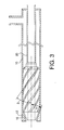
- FIG. 3 shows a schematic of an injector according to another embodiment of the present invention.
- indefinite articles “a” and “an” as used herein mean one or more when applied to any feature in embodiments of the present invention described in the specification and claims.
- the use of “a” and “an” does not limit the meaning to a single feature unless such a limit is specifically stated.
- the definite article “the” preceding singular or plural nouns or noun phrases denotes a particular specified feature or particular specified features and may have a singular or plural connotation depending upon the context in which it is used.
- the adjective “any” means one, some, or all indiscriminately of whatever quantity.
- reference to “an embodiment” does not limit the meaning to a single embodiment.
- the present invention relates to an injector for injecting a fossil fuel and an oxidant into a shaft furnace.
- Blast furnaces and cupolas are examples of shaft furnaces.
- an injector 1 is shown, illustrating an embodiment according to the present invention.
- the fossil fuel may comprise solid fossil fuel, e.g. coal, and/or liquid fossil fuel, e.g. oil.
- the oxidant may comprise air, industrial oxygen, or mixtures thereof.
- Industrial oxygen is defined herein to be a gas comprising 80% to 100% oxygen.
- the injector 1 comprises a conduit 10 having a first end portion for receiving oxidant through an oxidant inlet 14 and a second end portion terminating substantially with a converging inner surface 12 for passing the oxidant into at least one of a blast passageway 23 , 24 and a raceway cavity 50 .
- the second end portion has a converging inner surface 12 through at least a part of the second end portion.
- the angle, shown as ⁇ in FIG. 1, of the converging inner surface relative to the longitudinal axis of conduit 10 may be 5° to 45° or 10° to 30°.
- the blast passageway includes the passage 24 within the blow pipe 14 and the passage 23 within the tuyere 13 as shown in FIG. 2.
- the injector 1 may be constructed from any suitable material known in the art, for example, stainless steels and other oxygen compatible materials capable of withstanding the hot blast temperature.
- the injector 1 further comprises a conduit 20 having a first end portion for receiving the fossil fuel through an inlet 15 and a second end portion disposed substantially within the second end portion of conduit 10 .
- the second end portion of conduit 20 defines a fossil fuel passage 26 for passing the fossil fuel into at least one of the blast passageway 23, 24 and the raceway cavity 50 .
- Conduit 20 may be coaxial with conduit 10 .
- Injector 1 further comprises a means for swirling the oxidant wherein the means for swirling the oxidant is at least partially disposed between the fossil fuel passage 26 and the second end portion of conduit 10 .
- the means for swirling the oxidant defines a plurality of spiral-like passages 30 having a rotation of at least 90 degrees or at least 120 degrees.
- the means for swirling the oxidant may be machined into the surface of conduit 20 , shown as grooves in conduit 20 . Although shown as grooves in conduit 20 , swirl vanes or other means for swirling the oxidant known in the art may also be used.
- the apparatus according to the invention may comprise one or more of the following characteristics, taken alone or in any possible technical combinations.
- the means for swirling the oxidant may have a shape that is complementary to the second end portion of conduit 10 .
- the means for swirling the oxidant may continue into the converging section of conduit 10 such that the means for swirling the oxidant has a shape complementary to the converging inner surface 12 .
- the means for swirling the oxidant may be adjacent to the converging inner surface 12 . Since, as shown in the embodiment in FIG. 1, the spiral-like passages 30 continue from a cylindrical, nonconverging section of conduit 10 through a converging section of conduit 10 , the spiral diameter of the plurality of spiral-like passages 30 is greater at the inlet end 18 of the spiral-like passages 30 than at the outlet end 19 of the spiral-like passages 30 .
- the spiral diameter of the spiral-like passages 30 may have a shape that is complementary to the second end portion of conduit 10.
- the plurality of spiral-like passages 30 may have a length-averaged swirl angle of 25° to 65° or 35° to 45°.
- the swirl angle is defined as the angle between the tangent line through a spiral-like passage superimposed on the longitudinal axis of the fossil fuel passage, shown in FIG. 1 as ⁇ .
- the swirl angle may remain substantially constant over the length of the swirl means from the inlet end 18 to the outlet end 19 of the spiral-like passages 30 .
- a substantially constant swirl angle is defined herein to mean within 5°. If desired, the swirl angle may vary over the length of the swirl means from the inlet end 18 to the outlet end 19 of the spiral-like passages 30 .
- the plurality of spiral-like passages may have a generally rectangular cross-section.
- leading edge of conduit 10 and the leading edge of conduit 20 are shown in FIG. 1 to be flush with each other, the leading edge of conduit 20 may be recessed within the second end portion of conduit 10 . The leading edge of conduit 20 may also slightly extend beyond the outlet of conduit 10 .
- the outlets of conduits 10 and 20 may be circular or some other suitable shape, for example slightly oval. If the shape is other than circular, the outlet dimension may be characterized in terms of a hydraulic diameter. In case the cross section is circular, the hydraulic diameter and diameter are equivalent. According to an aspect of the invention, the distance between the geometric center of the outlet of conduit 10 and the geometric center of the outlet of conduit 20 is less than the hydraulic diameter of the outlet of conduit 20 .
- Injector 1 may further comprise a converging annular passage 16 for receiving oxidant from the plurality of spiral-like passages 30 .
- the converging annular passage 16 is defined between at least a portion the converging inner surface 12 and at least one of the conduit 20 and the means for swirling the oxidant.
- the converging annular passage 16 may extend through only a portion of the converging inner surface 12 as shown in FIG. 1.
- the converging annular passage 16 allows the discrete oxidant jets from the spiral-like passages 30 to expand and merge thereby providing a more continuous rotating vortex of oxidant prior to contacting the fossil fuel leaving conduit 20 . By allowing the high velocity oxidant jets to expand and merge into a rotating vortex, localized turbulence and potentially damaging flame attachment at the tip of the injector are both suppressed.
- the converging annular passage 16 may extend through the entire converging inner surface 12.
- FIG. 3 also shows the leading edge of conduit 20 slightly recessed within the second end portion of conduit 10 .
- FIG. 3 also shows the second end portion of conduit 10 having a short cylindrical section downstream of the converging inner surface 12 that does not materially impact the flow characteristics of the oxidant stream and therefore corresponds to a second end portion terminating substantially with a converging inner surface.
- the invention in another embodiment, with reference to FIG. 1 and FIG. 2, relates to a shaft furnace comprising a blast passageway 23, 24 , a raceway cavity 50 and any of the injector embodiments for injecting a fossil fuel and an oxidant into the shaft furnace as described above.
- the injector of the present invention may be used in the same manner as conventional injectors.
- the injector comprised an inner conduit having a generally circular cross-section for conveying fossil fuel and an outer conduit, also having a generally circular cross-section, surrounding the inner conduit, which formed an annulus for conveying and swirling oxidant.
- the inner diameter of the inner conduit was about 8.687 mm.
- the outer diameter of the outer conduit was about 48.26 mm and the inner diameter of the outer conduit was about 29.49 mm.
- the inner surface of the outer conduit terminated in a converging inner surface having an angle of about 15° relative to the longitudinal axis.
- the means for swirling the oxidant comprised six evenly-spaced spiral-like passages (grooves) machined into the outer surface of the inner conduit and had a rotation of about 180°.
- the spiral-like passages were generally rectangular, having width and height dimensions of about 2.5 mm by 2.5 mm.
- the swirl angle of the spiral-like passages was about 40°.
- the axial length of the swirl section was about 63.5 mm and continued into the converging section.
- the injector included a converging annular passage having a length of about 9 mm and height of about 2.5 mm.
- the leading edge of inner conduit was recessed within the outer conduit by about 3 mm.
- the experiments were conducted using pulverized coal as the fossil fuel.
- the injector was tested with and without swirling oxidant.
- the swirling oxidant was oxygen from a liquid tank and was essentially pure oxygen. For cases where no swirling oxidant was used, the injector acted as a conventional straight bore injection lance.
- Combustion air at ambient temperature was introduced into a hot furnace at a flow rate of about 2113 Nm 3 /h.
- the injector injected pulverized coal and optionally swirl oxidant into the combustion air stream entering the hot furnace to simulate the conditions of a blast passageway and/or raceway cavity.
- the pulverized coal was conveyed through the injector by about 35 m 3 /h of transport air.
- Solid particles were collected from the exhaust stream for various operating conditions. The solid particles were analyzed for unburned carbon by the Percentage Loss on Ignition (LOI) method. The more carbon soot present in the sample, the greater percentage of the sample weight is lost. Less carbon soot production is desired for the shaft furnace process; therefore a lower LOI is desirable.
- LOI Percentage Loss on Ignition
- Table 1 summarizes process conditions and LOI results. Sample numbers 1-1 and 1-2 are to be compared with sample numbers 2-1 and 2-2. Sample numbers 3-1 and 3-2 are to be compared with sample numbers 4-1 and 4-2.
- the injector was tested at various coal flow rates.
- the combustion air flow rate was maintained constant and the coal flow rate was adjusted to maintain about the same overall stoichiometric ratio for comparison cases.
- the roughly equivalent overall stoichiometric ratio is confirmed by the similar oxygen concentrations of the exhaust gas as shown in Table 1.
- the LOI data shows that, on average, the samples corresponding to operating conditions with swirl oxidant have a lower percentage loss on ignition, indicating less carbon soot produced for the injector according to the present invention.
- Table 1 Sample # Coal flow rate (kg/h) Swirl O 2 flow rate (Nm 3 /h) Exhaust O 2 (vol %) LOI (%) 1-1 251.0 59 2.75 29.53 1-2 251.0 59 2.2 17.83 2-1 219.5 0 2.2 21.52 2-2 218.7 0 2.2 56.87 3-1 269.7 0 1.7 29.59 3-2 269.5 0 1.5 49.64 4-1 304.7 72 1.7 22.10 4-2 305.3 72 1.6 39.22
- a second injector according to the present invention was constructed and tested. This second injector was similar to the injector described in Example 1 with the exception that the cross-section of the spiral-like passages, which had a width of about 2.5 mm and a height of about 1.25 mm. The cross-sectional area of the spiral-like passages was therefore halved, resulting in a higher flow velocity for the same flow rate compared to the injector in Example 1.
- Table 2 summarizes process conditions and LOI results for the injector having higher oxidant swirl velocity.
- the LOI data shows that the samples corresponding to operating conditions with swirl oxidant have a lower percentage loss on ignition, indicating less carbon soot produced for the injector according to the present invention.
- Exhaust 02 concentrations were not measured for Samples 6-1 and 6-2.
- Table 2 Sample # Coal flow rate (kg/h) Swirl O 2 flow rate (Nm 3 /h) Exhaust O 2 (vol %) LOI (%) 6-1 250 59 --- 36.09 6-2 220 0 --- 49.29
Landscapes
- Engineering & Computer Science (AREA)
- Chemical & Material Sciences (AREA)
- Mechanical Engineering (AREA)
- General Engineering & Computer Science (AREA)
- Manufacturing & Machinery (AREA)
- Materials Engineering (AREA)
- Metallurgy (AREA)
- Organic Chemistry (AREA)
- Combustion & Propulsion (AREA)
- Manufacture Of Iron (AREA)
Abstract
Description
- The present invention relates generally to fossil fuel injection into a shaft furnace. More specifically, the present invention relates to a fossil fuel injector where oxidant, which may be industrial grade oxygen, is swirled around the fossil fuel, which may be pulverized coal, to improve the combustion of the fossil fuel thereby permitting increased substitution of fossil fuel for coke.
- Generally, in the production of molten iron in a shaft furnace, for example a blast furnace or a cupola, iron ore and/or iron scrap as a raw material and coke as a fuel are fed through the top of the furnace, while (hot) blast air is fed through a tuyere, which is positioned in a lower part of the furnace. The coke provides three main functions: fuel, reductant, and gas flow passage. Coke serves as fuel, reacting with blast air to provide a large part of the heat energy needed for the process. Coke serves as a reductant, both as a carbon constituent in carbon monoxide, which is needed for reducing the ore by the so-called "indirect reduction", and also as carbon, which is needed for reducing the ore by so-called "direct reduction," where carbon directly contacts heated and partially reduced oxides of iron. Coke also, due to its porosity, serves as a gas flow passage, allowing process gases to pass upward through the shaft furnace. As the coke is burned and the iron ore reduced, molten iron and slag are produced. Molten iron and slag are tapped from a position near the bottom of the shaft furnace.
- For economic reasons, fossil fuels e.g. oil, natural gas, and coal, are injected into shaft furnaces to reduce the amount of coke needed for the process. Fossil fuels are typically injected into the blast passageway and/or the raceway of the shaft furnace. The blow pipe and tuyere make up the blast passageway. A number of shaft furnaces, particularly blast furnaces, around the world practice some form of fossil fuel injection thereby substituting more expensive coke with less-expensive fossil fuel(s). Pulverized coal is the most common fossil fuel injected to reduce coke usage. Economics favor increased use of pulverized coal thereby reducing the use of coke, but technical problems limit pulverized coal utilization.
- As described above, one of the main functions of the coke is to serve as a gas flow passage, which is provided through its porosity. Process gases move upward through the shaft furnace through the pores in the coke as the charge (also called burden) moves downward. Preferably, the permeability of the charge is evenly distributed, allowing reducing gases to permeate throughout the charge and minimizing channeling. Uniform permeability is important for smooth operation of a shaft furnace. Insufficient and/or uneven permeability leads to nonuniform gas flows across the cross section of the furnace, resulting in nonuniform reduction of the charge and irregular decent of the charge.
- As pulverized coal injection is increased, inadequate mixing between the injected coal and the blast air results in incomplete combustion of the injected coal, resulting in carbon soot formation. Since the velocity of the pulverized coal is high, and the raceway dimensions are only about 1 to 2 meters in length in a typical blast furnace, individual particles of coal have little time to completely combust or react. This problem also exists for other fossil fuels, such as heavy oil. Soot plugs the pores in the coke, inhibiting the gas flow characteristics, and thereby limits the amount of coal that can be injected to replace coke.
- As greater amounts of fossil fuel are injected, industrial oxygen has been added to the process to boost furnace productivity and balance the cooling effect of the additionally injected fossil fuels. Injection of fossil fuel without industrial oxygen may decrease the temperature in the raceway due to endothermic cracking of the fossil fuel and the thermal capacity of the relatively cold fossil fuel. Industrial oxygen helps maintain the flame temperature in the raceway. The addition of oxygen also helps to improve the throughput of the furnace. Injection of both fossil fuel and industrial oxygen allows operators to increase production without exceeding acceptable tuyere-zone temperatures. Oxygen may be injected along with the fossil fuel, through separate passages in an injector, and/or blended with the blast air. The industrial oxygen may be blended with the blast air upstream and/or downstream of the stoves to provide an overall oxygen enrichment of the blast air.
-
- Since fossil fuels such as coal are less expensive than coke, it is desirable to substitute fossil fuel for coke, at levels greater than before, while maintaining smooth furnace operation.
- It is desirable to provide more complete combustion of the fossil fuel thereby minimizing accumulation of unburned fossil fuel, for example soot, in the pores and interstices of the coke.
- Pulverized coal is abrasive and may erode nozzle tips. It is desirable to provide an injector for coal that is resistant to erosion.
- It is desirable to provide an injector for a shaft furnace that is resistant to overheating.
- The present invention is intended to overcome the disadvantages of the prior art fossil fuel injectors used in shaft furnaces, while providing the desired benefits.
- In an embodiment, the present invention relates to an injector for injecting a fossil fuel and an oxidant into a shaft furnace comprising a first conduit terminating substantially in a converging nozzle for passing the oxidant into a blast passageway and/or a raceway cavity, a second conduit having a nozzle disposed substantially within the converging nozzle of the first conduit for passing the fossil fuel into the blast passageway and/or the raceway cavity, and a means for swirling the oxidant defining a plurality of spiral-like passages having a rotation of at least 90 degrees or at least 120 degrees.
- In another embodiment, the present invention relates to an injector for injecting a fossil fuel and an oxidant into a shaft furnace comprising a first conduit having a converging inner surface proximate the outlet end portion for passing the oxidant into a blast passageway and/or a raceway cavity, a second conduit having an outlet end portion disposed substantially within the outlet end portion of the first conduit for passing the fossil fuel into the blast passageway and/or the raceway cavity, and a means for swirling the oxidant defining a plurality of spiral-like passages having a rotation of at least 90 degrees or at least 120 degrees, wherein the distance between the outlet centers is less than the (hydraulic) diameter of the outlet of the second conduit.
- In another embodiment, the present invention relates to an injector for injecting pulverized coal and industrial-grade oxygen into a blast furnace comprising a first conduit terminating substantially with a converging nozzle for passing the industrial-grade oxygen into a blast passageway and/or raceway cavity, and a second conduit having a nozzle disposed substantially within the converging nozzle of the first conduit for passing the pulverized coal into the blast passageway and/or raceway cavity, the second conduit defining spiral-like passages on its outer surface having a rotation of at least 120 degrees.
- In another embodiment, the present invention relates to a shaft furnace comprising a blast passageway, a raceway cavity in fluid communication with the blast passageway, and an injector for injecting a fossil fuel and an oxidant into the blast passageway and/or the raceway cavity, the injector comprising a first conduit terminating substantially with a converging nozzle for passing the oxidant into a blast passageway and/or a raceway cavity, a second conduit having a nozzle disposed substantially within the converging nozzle of the first conduit for passing the fossil fuel into the blast passageway and/or the raceway cavity, and a means for swirling the oxidant defining a plurality of spiral-like passages having a rotation of at least 90 degrees or at least 120 degrees.
- The means for swirling the oxidant may be formed on the outer surface of the second conduit such that the second conduit comprises the means for swirling the oxidant.
- The means for swirling the oxidant may have a shape that is complementary to the converging nozzle of the first conduit and may be adjacent to the converging nozzle of the first conduit.
- The plurality of spiral-like passages may have an average swirl angle of 25° to 65°. The swirl angle of the spiral-like passages may be substantially constant over the length of the spiral-like passages.
- The leading edge of the second conduit may be recessed within the converging nozzle of the first conduit.
- The injector may include a converging annular passage for receiving the oxidant from the plurality of spiral-like passages to expand and merge discrete oxidant jets into a rotating vortex for suppressing flame attachment at the tip of the injector. The converging annular passage may extend through a portion or the entire converging nozzle.
- FIG. 1 shows a schematic of an injector according to an embodiment of the present invention.
- FIG. 2 shows a schematic showing an injector, blow pipe, tuyere, and raceway cavity.
- FIG. 3 shows a schematic of an injector according to another embodiment of the present invention.
- The indefinite articles "a" and "an" as used herein mean one or more when applied to any feature in embodiments of the present invention described in the specification and claims. The use of "a" and "an" does not limit the meaning to a single feature unless such a limit is specifically stated. The definite article "the" preceding singular or plural nouns or noun phrases denotes a particular specified feature or particular specified features and may have a singular or plural connotation depending upon the context in which it is used. The adjective "any" means one, some, or all indiscriminately of whatever quantity. Likewise, reference to "an embodiment" does not limit the meaning to a single embodiment.
- In an embodiment, the present invention relates to an injector for injecting a fossil fuel and an oxidant into a shaft furnace. Blast furnaces and cupolas are examples of shaft furnaces. With reference to FIG. 1 and FIG. 2, an injector 1 is shown, illustrating an embodiment according to the present invention. The fossil fuel may comprise solid fossil fuel, e.g. coal, and/or liquid fossil fuel, e.g. oil. The oxidant may comprise air, industrial oxygen, or mixtures thereof. Industrial oxygen is defined herein to be a gas comprising 80% to 100% oxygen.
- The injector 1 comprises a
conduit 10 having a first end portion for receiving oxidant through anoxidant inlet 14 and a second end portion terminating substantially with a converginginner surface 12 for passing the oxidant into at least one of ablast passageway raceway cavity 50. The second end portion has a converginginner surface 12 through at least a part of the second end portion. The angle, shown as α in FIG. 1, of the converging inner surface relative to the longitudinal axis ofconduit 10 may be 5° to 45° or 10° to 30°. The blast passageway includes thepassage 24 within theblow pipe 14 and thepassage 23 within thetuyere 13 as shown in FIG. 2. - The injector 1 may be constructed from any suitable material known in the art, for example, stainless steels and other oxygen compatible materials capable of withstanding the hot blast temperature.
- The injector 1 further comprises a
conduit 20 having a first end portion for receiving the fossil fuel through aninlet 15 and a second end portion disposed substantially within the second end portion ofconduit 10. The second end portion ofconduit 20 defines afossil fuel passage 26 for passing the fossil fuel into at least one of theblast passageway raceway cavity 50.Conduit 20 may be coaxial withconduit 10. - Injector 1 further comprises a means for swirling the oxidant wherein the means for swirling the oxidant is at least partially disposed between the
fossil fuel passage 26 and the second end portion ofconduit 10. The means for swirling the oxidant defines a plurality of spiral-like passages 30 having a rotation of at least 90 degrees or at least 120 degrees. The means for swirling the oxidant may be machined into the surface ofconduit 20, shown as grooves inconduit 20. Although shown as grooves inconduit 20, swirl vanes or other means for swirling the oxidant known in the art may also be used. - The apparatus according to the invention may comprise one or more of the following characteristics, taken alone or in any possible technical combinations.
- As shown in FIG. 1, the means for swirling the oxidant may have a shape that is complementary to the second end portion of
conduit 10. The means for swirling the oxidant may continue into the converging section ofconduit 10 such that the means for swirling the oxidant has a shape complementary to the converginginner surface 12. The means for swirling the oxidant may be adjacent to the converginginner surface 12. Since, as shown in the embodiment in FIG. 1, the spiral-like passages 30 continue from a cylindrical, nonconverging section ofconduit 10 through a converging section ofconduit 10, the spiral diameter of the plurality of spiral-like passages 30 is greater at theinlet end 18 of the spiral-like passages 30 than at the outlet end 19 of the spiral-like passages 30. The spiral diameter of the spiral-like passages 30 may have a shape that is complementary to the second end portion ofconduit 10. - The plurality of spiral-
like passages 30 may have a length-averaged swirl angle of 25° to 65° or 35° to 45°. The swirl angle is defined as the angle between the tangent line through a spiral-like passage superimposed on the longitudinal axis of the fossil fuel passage, shown in FIG. 1 as β. The swirl angle may remain substantially constant over the length of the swirl means from theinlet end 18 to the outlet end 19 of the spiral-like passages 30. For the case where the spiral-like passages are machined into the surface ofconduit 20, the traverse of the cutting tool needs to be adjusted to maintain the proper lead due to the changing diameter in the converging section, in order to maintain a substantially constant swirl angle. A substantially constant swirl angle is defined herein to mean within 5°. If desired, the swirl angle may vary over the length of the swirl means from theinlet end 18 to the outlet end 19 of the spiral-like passages 30. - The plurality of spiral-like passages may have a generally rectangular cross-section.
- Although the leading edge of
conduit 10 and the leading edge ofconduit 20 are shown in FIG. 1 to be flush with each other, the leading edge ofconduit 20 may be recessed within the second end portion ofconduit 10. The leading edge ofconduit 20 may also slightly extend beyond the outlet ofconduit 10. - The outlets of
conduits conduit 10 and the geometric center of the outlet ofconduit 20 is less than the hydraulic diameter of the outlet ofconduit 20. - Injector 1 may further comprise a converging
annular passage 16 for receiving oxidant from the plurality of spiral-like passages 30. The convergingannular passage 16 is defined between at least a portion the converginginner surface 12 and at least one of theconduit 20 and the means for swirling the oxidant. The convergingannular passage 16 may extend through only a portion of the converginginner surface 12 as shown in FIG. 1. The convergingannular passage 16 allows the discrete oxidant jets from the spiral-like passages 30 to expand and merge thereby providing a more continuous rotating vortex of oxidant prior to contacting the fossilfuel leaving conduit 20. By allowing the high velocity oxidant jets to expand and merge into a rotating vortex, localized turbulence and potentially damaging flame attachment at the tip of the injector are both suppressed. - As shown in FIG. 3, the converging
annular passage 16 may extend through the entire converginginner surface 12. FIG. 3 also shows the leading edge ofconduit 20 slightly recessed within the second end portion ofconduit 10. FIG. 3 also shows the second end portion ofconduit 10 having a short cylindrical section downstream of the converginginner surface 12 that does not materially impact the flow characteristics of the oxidant stream and therefore corresponds to a second end portion terminating substantially with a converging inner surface. - In another embodiment, with reference to FIG. 1 and FIG. 2, the invention relates to a shaft furnace comprising a
blast passageway raceway cavity 50 and any of the injector embodiments for injecting a fossil fuel and an oxidant into the shaft furnace as described above. - The injector of the present invention may be used in the same manner as conventional injectors.
- The following examples are provided to illustrate the invention and benefits thereof. However, these examples are not to be construed to limit the scope of the present invention.
- An injector according to the present invention was constructed and tested. The injector comprised an inner conduit having a generally circular cross-section for conveying fossil fuel and an outer conduit, also having a generally circular cross-section, surrounding the inner conduit, which formed an annulus for conveying and swirling oxidant. The inner diameter of the inner conduit was about 8.687 mm. The outer diameter of the outer conduit was about 48.26 mm and the inner diameter of the outer conduit was about 29.49 mm. The inner surface of the outer conduit terminated in a converging inner surface having an angle of about 15° relative to the longitudinal axis.
- The means for swirling the oxidant comprised six evenly-spaced spiral-like passages (grooves) machined into the outer surface of the inner conduit and had a rotation of about 180°. The spiral-like passages were generally rectangular, having width and height dimensions of about 2.5 mm by 2.5 mm. The swirl angle of the spiral-like passages was about 40°. The axial length of the swirl section was about 63.5 mm and continued into the converging section. The injector included a converging annular passage having a length of about 9 mm and height of about 2.5 mm. The leading edge of inner conduit was recessed within the outer conduit by about 3 mm.
- The experiments were conducted using pulverized coal as the fossil fuel. The injector was tested with and without swirling oxidant. The swirling oxidant was oxygen from a liquid tank and was essentially pure oxygen. For cases where no swirling oxidant was used, the injector acted as a conventional straight bore injection lance.
- Combustion air at ambient temperature was introduced into a hot furnace at a flow rate of about 2113 Nm3/h. The injector injected pulverized coal and optionally swirl oxidant into the combustion air stream entering the hot furnace to simulate the conditions of a blast passageway and/or raceway cavity. The pulverized coal was conveyed through the injector by about 35 m3/h of transport air.
- Solid particles were collected from the exhaust stream for various operating conditions. The solid particles were analyzed for unburned carbon by the Percentage Loss on Ignition (LOI) method. The more carbon soot present in the sample, the greater percentage of the sample weight is lost. Less carbon soot production is desired for the shaft furnace process; therefore a lower LOI is desirable.
- Table 1 summarizes process conditions and LOI results. Sample numbers 1-1 and 1-2 are to be compared with sample numbers 2-1 and 2-2. Sample numbers 3-1 and 3-2 are to be compared with sample numbers 4-1 and 4-2.
- The injector was tested at various coal flow rates. The combustion air flow rate was maintained constant and the coal flow rate was adjusted to maintain about the same overall stoichiometric ratio for comparison cases. The roughly equivalent overall stoichiometric ratio is confirmed by the similar oxygen concentrations of the exhaust gas as shown in Table 1.
- The LOI data shows that, on average, the samples corresponding to operating conditions with swirl oxidant have a lower percentage loss on ignition, indicating less carbon soot produced for the injector according to the present invention.
Table 1. Sample # Coal flow rate
(kg/h)Swirl O2 flow rate
(Nm3/h)Exhaust O2
(vol %)LOI (%) 1-1 251.0 59 2.75 29.53 1-2 251.0 59 2.2 17.83 2-1 219.5 0 2.2 21.52 2-2 218.7 0 2.2 56.87 3-1 269.7 0 1.7 29.59 3-2 269.5 0 1.5 49.64 4-1 304.7 72 1.7 22.10 4-2 305.3 72 1.6 39.22 - A second injector according to the present invention was constructed and tested. This second injector was similar to the injector described in Example 1 with the exception that the cross-section of the spiral-like passages, which had a width of about 2.5 mm and a height of about 1.25 mm. The cross-sectional area of the spiral-like passages was therefore halved, resulting in a higher flow velocity for the same flow rate compared to the injector in Example 1.
- Table 2 summarizes process conditions and LOI results for the injector having higher oxidant swirl velocity. The LOI data shows that the samples corresponding to operating conditions with swirl oxidant have a lower percentage loss on ignition, indicating less carbon soot produced for the injector according to the present invention. Exhaust 02 concentrations were not measured for Samples 6-1 and 6-2.
Table 2. Sample # Coal flow rate
(kg/h)Swirl O2 flow rate
(Nm3/h)Exhaust O2
(vol %)LOI (%) 6-1 250 59 --- 36.09 6-2 220 0 --- 49.29
Claims (21)
- An injector for injecting a fossil fuel and an oxidant into a shaft furnace comprising:a first conduit having a first end portion for receiving the oxidant and a second end portion for passing the oxidant into at least one of a blast passageway and a raceway cavity, the second end portion terminating substantially with a converging inner surface;a second conduit having a first end portion for receiving the fossil fuel and a second end portion disposed substantially within the second end portion of the first conduit, the second end portion of the second conduit defining a fossil fuel passage for passing the fossil fuel into at least one of the blast passageway and the raceway cavity; anda means for swirling the oxidant at least partially disposed between the fossil fuel passage and the second end portion of the first conduit, the means for swirling the oxidant defining a plurality of spiral-like passages having a rotation of at least 90 degrees.
- The injector of claim 1 wherein the plurality of spiral-like passages have a rotation of at least 120 degrees.
- The injector of claim 1 or 2 wherein the second conduit comprises the means for swirling the oxidant.
- The injector of any one of claims 1 to 3 wherein the means for swirling the oxidant has a shape complementary to the second end portion of the first conduit.
- The injector of any one of claims 1 to 4 wherein the leading edge of the second conduit is recessed within the second end portion of the first conduit.
- The injector of any one of claims 1 to 5 wherein the means for swirling the oxidant is adjacent to the converging inner surface of the first conduit.
- The injector of any one of claims 1 to 6 wherein the converging inner surface of the second end portion of the first conduit and at least one of the second conduit and the means for swirling the oxidant define a converging annular passage for receiving oxidant from the plurality of spiral-like passages.
- The injector of claim 7 wherein the length of the converging annular passage extends through only a portion of the converging inner surface.
- The injector of claim 7 wherein the length of the converging annular passage extends through the entire converging inner surface.
- The injector of any one of claims 1 to 9 wherein the plurality of spiral-like passages have an inlet end and an outlet end and wherein the spiral diameter of the plurality of spiral-like passages is greater at the inlet end than at the outlet end.
- The injector of claim 10 wherein spiral diameter is complementary to the second end portion of the first conduit.
- The injector of any one of claims 1 to 11 wherein the plurality of spiral-like passages have an average swirl angle of 25° to 65°.
- The injector of claim 12 wherein the swirl angle of the spiral-like passages is substantially constant from the inlet end to the outlet end of the spiral-like passages.
- An injector for injecting a fossil fuel and an oxidant into a shaft furnace comprising:a first conduit having a first end portion for receiving the oxidant and a second end portion for passing the oxidant into at least one of a blast passageway and a raceway cavity, the second end portion having a converging inner surface through at least a part of the second end portion and terminating in a first outlet;a second conduit having a first end portion for receiving the fossil fuel and a second end portion disposed substantially within the second end portion of the first conduit, the second end portion of the second conduit defining a fossil fuel passage for passing the fossil fuel into at least one of the blast passageway and the raceway cavity, the second end portion of the second conduit terminating in a second outlet having a hydraulic diameter; anda means for swirling the oxidant at least partially disposed between the fossil fuel passage and the second end portion of the first conduit , the means for swirling the oxidant defining a plurality of spiral-like passages having a rotation of at least 90 degrees;wherein the distance between the geometric center of first outlet and the geometric center of the second outlet is less than the hydraulic diameter of the second outlet.
- The injector of claim 14 wherein the plurality of spiral-like passages have a rotation of at least 120 degrees.
- The injector of claim 14 or 15 wherein the converging inner surface of the second end portion of the first conduit and at least one of the second conduit and the means for swirling the oxidant define a converging annular passage for receiving oxidant from the plurality of spiral-like passages.
- The injector of claim 16 wherein the length of the converging annular passage extends through only a portion of the converging inner surface.
- The injector of claim 16 wherein the length of the converging annular passage extends through the entire converging inner surface.
- The injector of claim 14 wherein the plurality of spiral-like passages have an average swirl angle of 25° to 65° and wherein the swirl angle of the spiral-like passages is substantially constant from the inlet end to the outlet end of the spiral-like passages.
- An injector for injecting pulverized coal and industrial-grade oxygen into a blast furnace comprising:a first conduit having a first end portion for receiving the industrial-grade oxygen and a second end portion for passing the industrial-grade oxygen into at least one of a blast passageway and a raceway cavity, the second end portion terminating substantially with a converging inner surface; anda second conduit having a first end portion for receiving the pulverized coal and a second end portion disposed substantially within the second end portion of the first conduit, the second end portion of the second conduit defining a pulverized coal passage for passing the pulverized coal into at least one of the blast passageway and the raceway cavity, the second end portion of the second conduit defining spiral-like passages having a rotation of at least 120 degrees on the outer surface of the second end portion of the second conduit.
- A shaft furnace comprising:a blast passageway;a raceway cavity in fluid communication with the blast passageway; andan injector for injecting a fossil fuel and an oxidant into at least one of the blast passageway and the raceway cavity, the injector comprising:a first conduit having a first end portion for receiving the oxidant and a second end portion for passing the oxidant into at least one of the blast passageway and the raceway cavity, the second end portion terminating substantially with a converging inner surface;a second conduit having a first end portion for receiving the fossil fuel and a second end portion disposed substantially within the second end portion of the first conduit, the second end portion of the second conduit defining a fossil fuel passage for passing the fossil fuel into at least one of the blast passageway and the raceway cavity; anda means for swirling the oxidant at least partially disposed between the fossil fuel passage and the second end portion of the first conduit, the means for swirling the oxidant defining a plurality of spiral-like passages having a rotation of at least 90 degrees.
Applications Claiming Priority (1)
| Application Number | Priority Date | Filing Date | Title |
|---|---|---|---|
| US11/368,649 US20070205543A1 (en) | 2006-03-06 | 2006-03-06 | Oxidant-swirled fossil fuel injector for a shaft furnace |
Publications (1)
| Publication Number | Publication Date |
|---|---|
| EP1832664A1 true EP1832664A1 (en) | 2007-09-12 |
Family
ID=38180705
Family Applications (1)
| Application Number | Title | Priority Date | Filing Date |
|---|---|---|---|
| EP07004345A Withdrawn EP1832664A1 (en) | 2006-03-06 | 2007-03-02 | Oxidant-swirled fossil fuel injector for a shaft furnace |
Country Status (4)
| Country | Link |
|---|---|
| US (1) | US20070205543A1 (en) |
| EP (1) | EP1832664A1 (en) |
| CN (1) | CN101033841A (en) |
| RU (1) | RU2007108201A (en) |
Cited By (2)
| Publication number | Priority date | Publication date | Assignee | Title |
|---|---|---|---|---|
| ES2336060A1 (en) * | 2008-02-21 | 2010-04-07 | Grande Grupo Andaluz De Estudios, S.L. | Double flow burner for biofuels (Machine-translation by Google Translate, not legally binding) |
| EP2334985A4 (en) * | 2008-09-22 | 2014-08-06 | Darsell Karringten | Burner |
Families Citing this family (11)
| Publication number | Priority date | Publication date | Assignee | Title |
|---|---|---|---|---|
| CA2445818C (en) * | 2003-07-04 | 2009-12-22 | Holcim Ltd. | Method and system for process gas entrainment and mixing in a kiln system |
| US20120103237A1 (en) * | 2010-11-03 | 2012-05-03 | Ronny Jones | Tiltable multiple-staged coal burner in a horizontal arrangement |
| JP6012358B2 (en) * | 2012-09-20 | 2016-10-25 | 三菱重工業株式会社 | Blow pipe structure |
| CN105189373A (en) * | 2012-11-30 | 2015-12-23 | 康宁股份有限公司 | Swirling burner and process for submerged combustion melting |
| CN105180166B (en) * | 2015-08-11 | 2018-04-13 | 河南汇金智能装备有限公司 | A kind of burner nozzle |
| KR101745361B1 (en) * | 2016-06-07 | 2017-06-09 | 주식회사 포스코 | Pulverized coal injection lance |
| US10870899B2 (en) * | 2016-11-03 | 2020-12-22 | Berry Metal Company | Fluid assisted particle injector |
| JP6800796B2 (en) * | 2017-03-31 | 2020-12-16 | パンパシフィック・カッパー株式会社 | Raw material supply equipment, flash smelting furnace, nozzle members |
| CN111621609A (en) * | 2020-07-20 | 2020-09-04 | 四川冶金设备开发有限公司 | Energy-saving blast furnace coal powder spray gun |
| EP4735648A1 (en) * | 2023-06-29 | 2026-05-06 | ArcelorMittal | Double wall lance for injecting reducing agent and oxygen through a tuyere in a blast furnace |
| LU507599B1 (en) | 2024-06-27 | 2025-12-29 | Wurth Paul Sa | Injection lance for pulverized coal and other granular material |
Citations (4)
| Publication number | Priority date | Publication date | Assignee | Title |
|---|---|---|---|---|
| AU459472B2 (en) * | 1971-03-29 | 1975-03-11 | Nippon Koran Kabushiki Kaisha | A combustion process and apparatus for blast furnaces |
| WO1996021048A1 (en) * | 1994-12-29 | 1996-07-11 | Pohang Iron & Steel Co., Ltd. | Apparatus for melting fine particles containing carbon and method for melting such fine particles using the apparatus |
| WO1998025076A1 (en) * | 1996-12-04 | 1998-06-11 | Voest-Alpine Industrieanlagenbau Gmbh | Burner for the combustion of fine-grain to dustlike solid fuels |
| WO2000009763A1 (en) * | 1998-08-13 | 2000-02-24 | Pohang Iron & Steel Co., Ltd. | Pulverized coal injecting apparatus |
Family Cites Families (9)
| Publication number | Priority date | Publication date | Assignee | Title |
|---|---|---|---|---|
| US3758080A (en) * | 1968-12-31 | 1973-09-11 | Manus J Mac | Machine for producing aerated products |
| US3898078A (en) * | 1973-03-29 | 1975-08-05 | Youngstown Sheet And Tube Co | Method and apparatus for injecting refining oxygen in steelmaking processes |
| US4597342A (en) * | 1981-09-28 | 1986-07-01 | University Of Florida | Method and apparatus of gas-coal combustion in steam boilers |
| GB8506655D0 (en) * | 1985-03-14 | 1985-04-17 | British Steel Corp | Smelting shaft furnaces |
| SE500956C2 (en) * | 1991-01-17 | 1994-10-10 | Ssab Tunnplaat Ab | Blast position with carbon injection lance |
| JP3523716B2 (en) * | 1994-11-02 | 2004-04-26 | Jfeスチール株式会社 | Scrap melting method |
| US5544868A (en) * | 1995-07-31 | 1996-08-13 | National Steel Corporation | Blow pipe and gas lance for blast furance |
| US6090182A (en) * | 1997-10-29 | 2000-07-18 | Praxair Technology, Inc. | Hot oxygen blast furnace injection system |
| US6174161B1 (en) * | 1999-07-30 | 2001-01-16 | Air Products And Chemical, Inc. | Method and apparatus for partial oxidation of black liquor, liquid fuels and slurries |
-
2006
- 2006-03-06 US US11/368,649 patent/US20070205543A1/en not_active Abandoned
-
2007
- 2007-03-02 EP EP07004345A patent/EP1832664A1/en not_active Withdrawn
- 2007-03-05 RU RU2007108201/06A patent/RU2007108201A/en not_active Application Discontinuation
- 2007-03-06 CN CNA2007100857128A patent/CN101033841A/en active Pending
Patent Citations (4)
| Publication number | Priority date | Publication date | Assignee | Title |
|---|---|---|---|---|
| AU459472B2 (en) * | 1971-03-29 | 1975-03-11 | Nippon Koran Kabushiki Kaisha | A combustion process and apparatus for blast furnaces |
| WO1996021048A1 (en) * | 1994-12-29 | 1996-07-11 | Pohang Iron & Steel Co., Ltd. | Apparatus for melting fine particles containing carbon and method for melting such fine particles using the apparatus |
| WO1998025076A1 (en) * | 1996-12-04 | 1998-06-11 | Voest-Alpine Industrieanlagenbau Gmbh | Burner for the combustion of fine-grain to dustlike solid fuels |
| WO2000009763A1 (en) * | 1998-08-13 | 2000-02-24 | Pohang Iron & Steel Co., Ltd. | Pulverized coal injecting apparatus |
Cited By (3)
| Publication number | Priority date | Publication date | Assignee | Title |
|---|---|---|---|---|
| ES2336060A1 (en) * | 2008-02-21 | 2010-04-07 | Grande Grupo Andaluz De Estudios, S.L. | Double flow burner for biofuels (Machine-translation by Google Translate, not legally binding) |
| ES2336060B1 (en) * | 2008-02-21 | 2011-03-22 | Grande Grupo Andaluz De Estudios, S.L. | DOUBLE FLOW BURNER FOR BIOFUELS. |
| EP2334985A4 (en) * | 2008-09-22 | 2014-08-06 | Darsell Karringten | Burner |
Also Published As
| Publication number | Publication date |
|---|---|
| RU2007108201A (en) | 2008-09-10 |
| US20070205543A1 (en) | 2007-09-06 |
| CN101033841A (en) | 2007-09-12 |
Similar Documents
| Publication | Publication Date | Title |
|---|---|---|
| US20070205543A1 (en) | Oxidant-swirled fossil fuel injector for a shaft furnace | |
| US6319458B1 (en) | Pulverized coal injecting apparatus | |
| US20130146680A1 (en) | Injection lance with variable swirl | |
| KR101555222B1 (en) | Blast furnace operating method and tube bundle-type lance | |
| EP2941594B1 (en) | Method for combusting fuel and burner therefor | |
| EP2746660A1 (en) | Method and apparatus for providing oxygen enriched fuel | |
| KR101314443B1 (en) | Blast furnace operation method, low-calorific-value gas combustion method for same, and blast furnace equipment | |
| CN101573456A (en) | Process for making pig iron in a blast furnace | |
| CN104704309B (en) | Method and apparatus for improving combustion of secondary fuels in a rotary kiln and method for retrofitting a rotary kiln with a burner assembly | |
| JP3733601B2 (en) | Apparatus for injecting pulverized coal for blast furnace and method for injecting pulverized coal in blast furnace | |
| US4138098A (en) | Method of blowing smelting shaft furnaces and tuyeres used for said blowing | |
| CN101868672B (en) | Combustion method and system | |
| KR101693136B1 (en) | Blast furnace operation method | |
| EP2796565B1 (en) | Blast furnace operation method | |
| CA2618411C (en) | Apparatus and method for injection of fluid hydrocarbons into a blast furnace | |
| JP4427469B2 (en) | Blast furnace pulverized coal injection burner and pulverized coal injection method using the same | |
| CN106147876A (en) | Gasification burner tip | |
| CN224033805U (en) | Process burner and reaction furnace | |
| CN219933968U (en) | An easy-to-cool burner | |
| JP3613902B2 (en) | Burner with pulverized coal injection into blast furnace | |
| JPH08157916A (en) | Method of blowing pulverized coal into blast furnace and lance for blowing pulverized coal | |
| CN110003957A (en) | A kind of process burner for airflow bed gasification furnace | |
| CN223755360U (en) | A burner for roasting anode carbon blocks | |
| JPH10251715A (en) | How to blow pulverized coal into the blast furnace | |
| RU35632U1 (en) | Lance |
Legal Events
| Date | Code | Title | Description |
|---|---|---|---|
| PUAI | Public reference made under article 153(3) epc to a published international application that has entered the european phase |
Free format text: ORIGINAL CODE: 0009012 |
|
| AK | Designated contracting states |
Kind code of ref document: A1 Designated state(s): AT BE BG CH CY CZ DE DK EE ES FI FR GB GR HU IE IS IT LI LT LU LV MC MT NL PL PT RO SE SI SK TR |
|
| AX | Request for extension of the european patent |
Extension state: AL BA HR MK YU |
|
| RIN1 | Information on inventor provided before grant (corrected) |
Inventor name: DUDILL, ROGER Inventor name: FARMER, LARRY KEITH Inventor name: LANYI, MICHAEL DENNIS |
|
| 17P | Request for examination filed |
Effective date: 20071009 |
|
| 17Q | First examination report despatched |
Effective date: 20071227 |
|
| AKX | Designation fees paid |
Designated state(s): AT BE BG CH CY CZ DE DK EE ES FI FR GB GR HU IE IS IT LI LT LU LV MC MT NL PL PT RO SE SI SK TR |
|
| STAA | Information on the status of an ep patent application or granted ep patent |
Free format text: STATUS: THE APPLICATION IS DEEMED TO BE WITHDRAWN |
|
| 18D | Application deemed to be withdrawn |
Effective date: 20080507 |