EP1831592B1 - Transmission with convex pulley sheaves and a drive belt - Google Patents
Transmission with convex pulley sheaves and a drive belt Download PDFInfo
- Publication number
- EP1831592B1 EP1831592B1 EP05825422A EP05825422A EP1831592B1 EP 1831592 B1 EP1831592 B1 EP 1831592B1 EP 05825422 A EP05825422 A EP 05825422A EP 05825422 A EP05825422 A EP 05825422A EP 1831592 B1 EP1831592 B1 EP 1831592B1
- Authority
- EP
- European Patent Office
- Prior art keywords
- transmission
- pulley
- contact
- drive belt
- range
- Prior art date
- Legal status (The legal status is an assumption and is not a legal conclusion. Google has not performed a legal analysis and makes no representation as to the accuracy of the status listed.)
- Not-in-force
Links
Images


Classifications
-
- F—MECHANICAL ENGINEERING; LIGHTING; HEATING; WEAPONS; BLASTING
- F16—ENGINEERING ELEMENTS AND UNITS; GENERAL MEASURES FOR PRODUCING AND MAINTAINING EFFECTIVE FUNCTIONING OF MACHINES OR INSTALLATIONS; THERMAL INSULATION IN GENERAL
- F16H—GEARING
- F16H9/00—Gearings for conveying rotary motion with variable gear ratio, or for reversing rotary motion, by endless flexible members
- F16H9/02—Gearings for conveying rotary motion with variable gear ratio, or for reversing rotary motion, by endless flexible members without members having orbital motion
- F16H9/04—Gearings for conveying rotary motion with variable gear ratio, or for reversing rotary motion, by endless flexible members without members having orbital motion using belts, V-belts, or ropes
- F16H9/12—Gearings for conveying rotary motion with variable gear ratio, or for reversing rotary motion, by endless flexible members without members having orbital motion using belts, V-belts, or ropes engaging a pulley built-up out of relatively axially-adjustable parts in which the belt engages the opposite flanges of the pulley directly without interposed belt-supporting members
- F16H9/125—Gearings for conveying rotary motion with variable gear ratio, or for reversing rotary motion, by endless flexible members without members having orbital motion using belts, V-belts, or ropes engaging a pulley built-up out of relatively axially-adjustable parts in which the belt engages the opposite flanges of the pulley directly without interposed belt-supporting members characterised by means for controlling the geometrical interrelationship of pulleys and the endless flexible member, e.g. belt alignment or position of the resulting axial pulley force in the plane perpendicular to the pulley axis
-
- F—MECHANICAL ENGINEERING; LIGHTING; HEATING; WEAPONS; BLASTING
- F16—ENGINEERING ELEMENTS AND UNITS; GENERAL MEASURES FOR PRODUCING AND MAINTAINING EFFECTIVE FUNCTIONING OF MACHINES OR INSTALLATIONS; THERMAL INSULATION IN GENERAL
- F16G—BELTS, CABLES, OR ROPES, PREDOMINANTLY USED FOR DRIVING PURPOSES; CHAINS; FITTINGS PREDOMINANTLY USED THEREFOR
- F16G5/00—V-belts, i.e. belts of tapered cross-section
- F16G5/16—V-belts, i.e. belts of tapered cross-section consisting of several parts
-
- F—MECHANICAL ENGINEERING; LIGHTING; HEATING; WEAPONS; BLASTING
- F16—ENGINEERING ELEMENTS AND UNITS; GENERAL MEASURES FOR PRODUCING AND MAINTAINING EFFECTIVE FUNCTIONING OF MACHINES OR INSTALLATIONS; THERMAL INSULATION IN GENERAL
- F16H—GEARING
- F16H61/00—Control functions within control units of change-speed- or reversing-gearings for conveying rotary motion ; Control of exclusively fluid gearing, friction gearing, gearings with endless flexible members or other particular types of gearing
- F16H61/66—Control functions within control units of change-speed- or reversing-gearings for conveying rotary motion ; Control of exclusively fluid gearing, friction gearing, gearings with endless flexible members or other particular types of gearing specially adapted for continuously variable gearings
- F16H61/662—Control functions within control units of change-speed- or reversing-gearings for conveying rotary motion ; Control of exclusively fluid gearing, friction gearing, gearings with endless flexible members or other particular types of gearing specially adapted for continuously variable gearings with endless flexible members
- F16H61/66272—Control functions within control units of change-speed- or reversing-gearings for conveying rotary motion ; Control of exclusively fluid gearing, friction gearing, gearings with endless flexible members or other particular types of gearing specially adapted for continuously variable gearings with endless flexible members characterised by means for controlling the torque transmitting capability of the gearing
Definitions
- the present invention relates to a drive belt for a continuously variable transmission provided with a pulley with convex sheaves, as described in the preamble of Claim 1.
- the structure and operation of a transmission of this type is considered to be known, for example from European Patent publication number 1218654 , which also shows one of the known types of drive belts or chains.
- the drive belt shown is generally known as the Van Doorne push belt and is described in more detail, for example, in patent publication WO-A-2002/061304 .
- This push belt is characterized, inter alia, by a series of transverse elements comprising a lower body, a middle body and an upper body.
- the lateral sides of the lower body are in this case provided with contact surfaces for contact with the the sheaves of a driving or primary pulley and those of a driven or secondary pulley of the transmission, while part of the top side of the lower body, facing the top body, i.e.
- a radially outwardly oriented edge thereof forms a supporting surface for a continuous tensioning element, which is generally formed by one or more groups of a number of nested, flat, relatively thin rings made from metal.
- the top body of the transverse elements which is substantially in the shape of an arrowhead, is located radially outside the tensioning element, and retains it in the vertical direction, while the middle body, which is located at the level of the tensioning element, connects the lower body and upper body to one another.
- the transverse elements are accommodated in the drive belt such that they can move with respect to the circumferential direction of the tensioning element.
- the Van Doorne push belt includes a, number of the said transverse elements which is such that at least virtually the entire circumference of the tensioning element is filled. Partly as a result of this, a driving power can be transmitted between the pulleys of the transmission, with the transverse elements advancing one another, with support and guidance from the tensioning element.
- Drive belts of this type are generally used in a transmission with two pulleys, each provided with two sheaves in the form of straight truncated cones, of which for cost reasons only one sheave is mounted such that it can move in the axial direction with respect to the other sheave, i.e. the fixed sheave, and a respective pulley axle in order to change the running radius of the drive belt between the pulley sheaves and therefore the transmission ratio of the transmission, which latter is given by the quotient of the running radii at the location of the two pulleys.
- the analysis on which the present invention is based has the purpose of filling this gap and of providing a definition of the radial curvature radius of the contact surfaces of the transverse elements. More particularly, the invention provides insight into the relevant working principles of the transmission and, based on the above, arrives at a design rule for optimally establishing the abovementioned curvature radius in the radial direction of the contact surfaces.
- the design rule according to the invention deviates from the solution which is obvious to the mechanical engineering designer, which is to use a value which is constant and as high as possible, determined by the available dimension of the contact surfaces - i.e. the height dimension of the lower body - and the said range of pulley angles in the transmission which should also be present in the contact surfaces.
- the present invention provides a drive belt which uses the combination of measures according to Claim 1.
- the radial curvature radius of the contact surfaces thereof or its profile is matched to the profile of the radius of curvature in the tangential direction used for the pulley sheaves, in which context the prevention of slipping of the drive belt with respect to the pulley sheaves is the most important design criterion.
- wear to the contact surfaces during operation is uniformly distributed and partly as a result is advantageously low.
- FIG. 1 diagrammatically depicts a cross section through a continuously variable transmission 1 according to the prior art.
- the known transmission 1 comprises a primary pulley 2, which can be driven by an engine (not shown), with a couple of forces Tp, and a secondary pulley 3, which can drive a load (not shown) with a couple of forces Ts.
- Both pulleys 2 and 3 are provided with a pulley sheave 21, 31 which is secured fixedly to the respective pulley axle 20, 30 and with a pulley sheave 22, 32 which can be displaced in the axial direction with respect to the said axle 20, 30.
- a drive belt 10, more particularly a push belt 10, is clamped between the pulley sheaves 21, 22, 31, 32, so that mechanical power can be transmitted between the two axles 20 and 30 with the aid of friction.
- An axially oriented force with which the drive belt 10 is clamped for each pulley 2, 3, to be referred to below as the primary clamping force Kp and the secondary clamping force Ks, respectively, is in this case realized by applying a hydraulic pressure in a respective pressure chamber 24, 34 of the two pulleys 2 and 3.
- a transmission controller (not shown) is used to determine and realize the force levels desired for the clamping forces Kp, Ks.
- the transmission ratio Rs/Rp of the transmission 1 is given by the ratio between a secondary running radius Rs and a primary running radius Rp of the drive belt 10, i.e. the effective radial position thereof between the pulley sheaves 21, 22, 31 and 32 of the respective pulleys 2 and 3.
- the said running radii Rp and Rs, and therefore the transmission ratio Rs/Rp, defined in accordance with the invention, of the transmission 1 can be varied by causing the displaceable sheaves 22, 32 to move in opposite axial directions along the respective pulley axles 20, 30.
- Figure 1 illustrates the transmission 1 by way of example with a low transmission ratio Rs/Rp, i.e. with a relatively large primary running radius Rp and a relatively small secondary running radius Rs.
- the transmission ratio Rs/Rp, the primary running radius Rp and the secondary running radius Rs are in an unambiguously defined and geometrically determined relationship with one another, which is determined, inter alia, by the length of the drive belt 10, the distance between the axes of rotation of the respective pulleys 2, 3 and the largest and smallest possible running radii Rp and Rs, so that they can be calculated from one another as required.
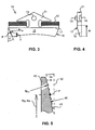
- Figure 2 shows the known transmission 1 once again, in the form of an axial side view, with the primary pulley 2 having the primary axle 20 on the left-hand side of the figure and the secondary pulley 3 having the secondary axle 30 on the right-hand side of the figure.
- the transmission 1 is illustrated with a relatively high transmission ratio Rs/Rp, in which the primary running radius Rp is smaller than the secondary running radius Rs.
- the drive belt 10 shown is what is known as a push belt 10 which comprises a virtually continuous series of transverse elements 11, only some of which are shown, for the sake of simplicity, and at least one set 12 of a number of radially nested, continuous, flat and thin metal rings.
- This push belt 10 is shown in more detail in Figures 3 and 4, Figure 3 showing a cross section through the push belt 10 and Figure 4 showing a side view in the axial direction of a transverse element 11 from it.
- the cross section shows the front view of the transverse element 11, which is provided on either side with a recess, in each of which a set of rings 12 is accommodated.
- the sets of rings 12 and the transverse element 11 enclose one another in the radial or height direction, but the transverse elements 11 can move along the sets of rings 12 in the circumferential direction thereof.
- the transverse elements 11 are also provided with a protuberance in the circumferential direction of the push belt 10, i.e. stud 13, and with a pocket 14 arranged in an opposite main side of the element 11, which stud 13 and pocket 14 are used to stabilize the series of transverse elements 11 with respect to one another in the push belt 10.
- a bottom section 15 of the transverse element 11 at least effectively tapers radially inwards, so that adjacent transverse elements 11 can tilt with respect to one another and the push belt 10 can describe an arc, for example where it is clamped between the pulley sheaves 21, 22, 31, 32 of the respective pulleys 2 and 3.
- the abovementioned effective radial position i.e. the effective running radius Rp, Rs of the push belt 10 substantially corresponds to a radial position of the top side of the bottom section 15 of the transverse element 11, which top side is also referred to as the tilting line 17 of the transverse elements 11, along which they are in contact with one another in the said arc.
- the bottom section 15 is also provided on either side with what are known as contact surfaces 16, via which the transverse element 11 is clamped between the pulley sheaves 21, 22; 31, 32, the rotation of a driving pulley 2 being transmitted via friction to the clamped transverse elements 11.
- This can produce a considerable pushing force between the transverse elements 11, with the result that they advance one another along the ring sets 12 in the direction of the driven pulley 3.
- the pushing force which is present between the transverse elements 11 is virtually completely transmitted via friction thereof.
- the transverse elements 11 finally push one another back from the driven pulley 3 to the driving pulley 2 under a relatively low pushing force.
- the sets of rings 12 in this context ensure that the transverse elements 11 continue to follow the path intended for the push belt 10.
- Figure 5 illustrates a detail of a pulley sheave 43 based on a cross section through it as seen in the tangential direction.
- a running surface 40 of the pulley sheave 43 by means of which it comes into contact with a contact surface 16 of the transverse elements 11, is provided with a radial curvature with an optionally variable radial curvature radius Rr 40 , a pulley angle ⁇ p, ⁇ s defined between a tangent 41 and the radial direction 42 at a possible contact point P between the running surface 40 and the contact surface 16 increasing as seen in this radial direction.
- the running surfaces 40 in the transmission 1 describe a contour which can be defined as the relationship between the local pulley angle ⁇ p, ⁇ s and the transmission ratio Rs/Rp of the transmission 1, which determines the radial position Rp, Rs of the instantaneous contact point P.
- the said contours are generally identical for the two pulleys 21, 22; 31, 21 and are then respectively referred to as the primary pulley angle contour ⁇ p(Rs/Rp) and the secondary pulley angle contour ⁇ s(Rs/Rp), which generally do differ from one another.
- the associated profile of the radial curvature radius Rr 40 of the running surfaces 40 can in this case also be defined in relation to the transmission ratio Rs/Rp and is referred to as the radial convexity contour Rr 40 (Rs/Rp). Therefore, the running surfaces 40 in the transmission 1, as seen in the tangential cross section of Figure 5 , describe a contour which can be defined as the relationship between the local pulley angle ⁇ p, ⁇ s and the transmission ratio Rs/Rp of the transmission 1, which defines the radial position Rp, Rs of the instantaneous contact point P.
- the running surface 40 of the pulley sheave 43 is also curved in the tangential direction with a radius of curvature Rt 40 , which likewise varies with the radial position Rp, Rs of the said contact point P on the pulley sheave 43, i.e. the respective running radius Rp, Rs of the drive belt 10. Therefore, the tangential curvature radius Rt 40 of the running surfaces 40 can also be defined in relation to the transmission ratio Rs/Rp.
- the contact surfaces 16 of the transverse element 11, as seen in the cross section through the push belt 10 as shown in Figure 3 are also provided with a curvature.
- a range of contact angles ⁇ which should at least correspond to the range of pulley angles ⁇ covered by pulley angle contours ⁇ p(Rs/Rp) and ⁇ s(Rs/Rp) of the running surfaces 40 of the pulleys 2 and 3, is defined in the radial direction in the contour of the contact surfaces 16.
- the prior art does not provide any more detailed discussion as to how a range of contact angles ⁇ of this nature is to be implemented in the design of the transverse element 11, i.e.
- the contact angle contour ⁇ (h) can be defined as the profile of the contact angle ⁇ in relation to a vertical or radial position h on the contact surface 16 with respect to the total vertical dimension H thereof, which is illustrated in Figures 3 and 4 .
- the prior art does not describe any radial curvature radius Rr 16 or profile thereof for the contact surfaces 16. Therefore, the person skilled in the art will normally seek to use a constant radial curvature radius Rr 16 which is as high as possible, by means of which the required range of contact angles ⁇ is realized within the available total vertical dimension H of the contact surface 16.
- a design of this type does not generally represent the most optimum solution.
- the minimum secondary clamping force Ks required can be calculated in a corresponding way from the torque Ts supplied to the secondary pulley 3 and the secondary running radius Rs.
- the minimum secondary clamping force Ks required is equal to the minimum primary clamping force Kp required.
- one of these two clamping forces Kp and Ks will generally have to be greater than the other in order to adopt and/or maintain the desired transmission ratio Rs/Rp.
- the ratio between the clamping forces Kp and Ks which is required for an equilibrium state of the transmission 1, i.e. for a constant transmission ratio, known as the equilibrium clamping force ratio KpKs, has its origin in the equilibrium condition that for each pulley 2, 3 a tensile force Ft is generated in the sets of rings 12 of the drive belt 10, and these tensile forces should be equal to one another.
- the tensile force Ft for each pulley 2 and 3 is produced as a result of the radial forces Frp and Frs acting on the drive belt 10 in the radial direction, which forces Frp and Frs are generated as a result of the local contact angle ⁇ p, ⁇ s and the substantially axially oriented clamping force Kp, Ks applied between the sheaves 21 and 22, 31 and 32, respectively, for each pulley 2, 3. Therefore, the equilibrium clamping force ratio KpKs will be influenced through the specific primary pulley angle contour ⁇ p(Rs/Rp) used for each transmission 1 and the secondary pulley angle contour ⁇ s(Rs/Rp).
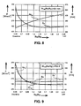
- Figures 6 and 7 which have been transferred from NL-1024918 , show what is known as a KpKs curve for two transmission designs, which are characterized by the pulley angle contours ⁇ p(Rs/Rp), ⁇ s(Rs/Rp) used therein, wherein the said equilibrium clamping force ratio KpKs is plotted in relation to the transmission ratio Rs/Rp of the transmission 1 in the range between the so-called Low and Overdrive transmission ratios Rs/Rp.
- Figures 6 and 7 also show the primary pulley angle contour ⁇ p(Rs/Rp) and the secondary pulley angle contour ⁇ s(Rs/Rp) of the respective transmission design.
- the equilibrium clamping force ratio KpKs varies from a value less than 1 in Low to a value greater than 1 in Overdrive.
- the equilibrium clamping force ratio KpKs at least for a transmission design in which the pulley angle contours ⁇ p(Rs/Rp), ⁇ s(Rs/Rp) also shown are used, is always greater than 1, so that in this case the primary clamping force Kp required for a constant transmission ratio Rs/Rp is always greater than the secondary clamping force Ks required for this purpose.
- this maximum permitted value also forms the optimum value for the contact pressure from an efficiency perspective, since if this value is used, on the one hand the transmission 1 can have the smallest possible volume and on the other hand, at least according to applicable tribological laws, the said torque transfer coefficient ⁇ T will adopt a high value, with the result that at a constant torque level lower clamping forces Kp, Ks can advantageously be used.
- the two insights referred to above in connection with the slipping pulley 2, 3 and the optimum contact pressure can unexpectedly and advantageously be combined to provide a completely new insight which gives rise to a guideline for the radial curvature radius Rr 16 of the contact surfaces 16 of the transverse elements 11 of the drive belt 10.
- the optimum value for the latter radius of curvature Rr 16 is in this case matched, in every transmission ratio Rs/Rp of the transmission 1, to the local radial and tangential curvature radii Rr 40 and Rt 40 of the running radius of the respective slipping pulley 2, 3, specifically in such a manner that the contact pressure between them has an at least approximately constant value, which preferably at least approximately corresponds to the said maximum permissible value for it.
- the profile of the optimum radial curvature radius Rr 16 over the height H of the contact surface 16 could in this case be determined empirically by experimentation, but it is also possible for the contact pressure in the local contact point of the contact surfaces 16 and the running surfaces 40 to be determined by calculation on the basis of the Hertzian elliptical point contact model. Applied to the present point contact between the pulleys 2, 3 and the drive belt 10, this model gives the following laws a to e:
- the profile of the radial curvature radius Rr 16 of the contact surfaces 16 can be approximated with sufficient accuracy by determining the optimum value for it in a limited number of, for example, 10, discrete transmission ratios Rs/Rp, and then determining the full flank contour Rr 16 (Rs/Rp) by fitting the calculated value with a polynomial function of at least the 4th order using, as boundary conditions, the two limit values for the contact angle ⁇ and for the present radial curvature radius Rr 16 , i.e. those which are required at the location of the contact point P at the highest and lowest values (Low; OD) of the range of transmission ratios Rs/Rp of the transmission 1.
- Figure 8 shows the profile, prescribed by the associated transmission design, of the tangential curvature radius Rt 40 of the running surface of the secondary pulley 3 in relation to the transmission ratio Rs/Rp, i.e. the said tangential convexity contour Rt 40 (Rs/Rp).
- the figure also shows the Hertzian contact pressure p H which will occur if the present flank contour Rr 16 (Rs/Rp) is used with a constant value, which is as high as possible, of the radial curvature radius Rr 16 of the contact surfaces 16, in this case 63 mm, which value is defined by the available height H of the contact surfaces 16 and the range of contact angles ⁇ (namely approximately 7.2° to 10.1° according to Figure 7 ).
- the Hertzian contact pressure p H adopts a relatively high value of some 275 N/mm 2 at most and moreover varies considerably in relation to the transmission ratio Rs/Rp.
- a flank contour Rr 16 (Rs/Rp) of this type is far from optimum and an advantageous lower maximum Hertzian contact pressure p H can be achieved within the boundary conditions of the height H of the contact surfaces 16 and the range of contact angles ⁇ . In this way, wear behaviour which is less extreme and, moreover, more constant between the various transmission ratios Rs/Rp will be obtained.
- Figure 9 shows the results of the above-discussed optimization method for determining the flank contour Rr 16 (Rs/Rp) for the transmission design with the KpKs curve from Figure 7 and the associated tangential convexity contour Rt 40 (Rs/Rp) of the secondary pulley 3 from Figure 8.
- Figure 9 gives the theoretically calculated curvature radius Rr 16 of the contact surface 16 of the transverse element 11 of the drive belt 10, i.e. the said flank contour Rr 16 (Rs/Rp), as well as the Hertzian contact pressure p H which occurs as a result during operation of the transmission 1.
- the Hertzian contact pressure p H adopts a relatively low value of about 205 N/mm 2 , which corresponds to a reduction of about 25% compared to the conventional transmission design from Figure 8 , and moreover has adopted a constant value, in accordance with the endeavours on which the invention is based.
- the Hertzian contact pressure p H which actually occurs will vary with a margin of around 10% about a mean value for this pressure, which is still always better by a factor of 2 than for the conventionally designed transmission 1 from Figure 8 .
- the present invention also leads to a considerable reduction in the (maximum) level of the Hertzian contact pressure p H or, as an alternative, to an advantageous reduction in the required height H of the contact surface 16.
- the invention also relates to the transmission 1 according to Claims 9 and 10, in the design of which the abovementioned insights illustrated in Figures 7 , 8 and 9 are embodied in concrete form, and which is otherwise in the form typical of the prior art.
Landscapes
- Engineering & Computer Science (AREA)
- General Engineering & Computer Science (AREA)
- Mechanical Engineering (AREA)
- Transmissions By Endless Flexible Members (AREA)
- Pulleys (AREA)
Abstract
Description
- The present invention relates to a drive belt for a continuously variable transmission provided with a pulley with convex sheaves, as described in the preamble of
Claim 1. - The structure and operation of a transmission of this type is considered to be known, for example from European Patent publication number
1218654 , which also shows one of the known types of drive belts or chains. The drive belt shown is generally known as the Van Doorne push belt and is described in more detail, for example, in patent publicationWO-A-2002/061304 . This push belt is characterized, inter alia, by a series of transverse elements comprising a lower body, a middle body and an upper body. The lateral sides of the lower body are in this case provided with contact surfaces for contact with the the sheaves of a driving or primary pulley and those of a driven or secondary pulley of the transmission, while part of the top side of the lower body, facing the top body, i.e. a radially outwardly oriented edge thereof, forms a supporting surface for a continuous tensioning element, which is generally formed by one or more groups of a number of nested, flat, relatively thin rings made from metal. The top body of the transverse elements, which is substantially in the shape of an arrowhead, is located radially outside the tensioning element, and retains it in the vertical direction, while the middle body, which is located at the level of the tensioning element, connects the lower body and upper body to one another. The transverse elements are accommodated in the drive belt such that they can move with respect to the circumferential direction of the tensioning element. - The Van Doorne push belt includes a, number of the said transverse elements which is such that at least virtually the entire circumference of the tensioning element is filled. Partly as a result of this, a driving power can be transmitted between the pulleys of the transmission, with the transverse elements advancing one another, with support and guidance from the tensioning element. Unlike in the case of the known chain, which is likewise formed from metal, or the known V-belt, which is made from composite material, both of which types of drive belt transmit the driving power by means of a tensile force, a virtually continuous series of transverse elements is clamped between the sheaves of a pulley, so that the clamping force which is exerted on the drive belt by this pulley during operation is distributed more or less uniformly over a relatively large number of contact surfaces. Therefore, the contact pressure which occurs between the drive belt, i.e. its transverse elements, and a pulley sheave as a result of the clamping force remains limited in relative terms.
- Drive belts of this type are generally used in a transmission with two pulleys, each provided with two sheaves in the form of straight truncated cones, of which for cost reasons only one sheave is mounted such that it can move in the axial direction with respect to the other sheave, i.e. the fixed sheave, and a respective pulley axle in order to change the running radius of the drive belt between the pulley sheaves and therefore the transmission ratio of the transmission, which latter is given by the quotient of the running radii at the location of the two pulleys. Various measures are known for overcoming the adverse effect of this, namely the fact that there is at least some degree of skew running of the drive belt between the pulleys, which degree of skew running varies with the transmission ratio. Measures of this type are generally realized in the drive belt itself, but may also form part of the transmission. An example of this latter option is given by
Japanese Patent publication JP-A-63-053352 - A similar drive belt is disclosed in
EP 1441151 A2 . - The Dutch Patent Application numbered
NL-A-1022157 NL-1023668 NL-1024918 - Where, according to the prior art, the radius of curvature or its profile over the radial dimension of the convex pulley sheave is given by the prescribed radial dimension of the pulley sheave and the effect which can be achieved by the respective convexity, relatively little attention is paid to the shaping of the contact surfaces of the transverse elements. Therefore, the analysis on which the present invention is based has the purpose of filling this gap and of providing a definition of the radial curvature radius of the contact surfaces of the transverse elements. More particularly, the invention provides insight into the relevant working principles of the transmission and, based on the above, arrives at a design rule for optimally establishing the abovementioned curvature radius in the radial direction of the contact surfaces. The design rule according to the invention deviates from the solution which is obvious to the mechanical engineering designer, which is to use a value which is constant and as high as possible, determined by the available dimension of the contact surfaces - i.e. the height dimension of the lower body - and the said range of pulley angles in the transmission which should also be present in the contact surfaces.
- According to the analysis which is expounded below in the description of the figures, the present invention to this end provides a drive belt which uses the combination of measures according to
Claim 1. In a drive belt of this type, the radial curvature radius of the contact surfaces thereof or its profile is matched to the profile of the radius of curvature in the tangential direction used for the pulley sheaves, in which context the prevention of slipping of the drive belt with respect to the pulley sheaves is the most important design criterion. As a result, in particular wear to the contact surfaces during operation is uniformly distributed and partly as a result is advantageously low. - The present invention is explained in more detail below with reference to the appended figures, in which:
-
Figure 1 diagrammatically depicts a cross section through a continuously variable transmission provided with two pulleys and a drive belt according to the prior art, -
Figure 2 shows a simplified side view of the transmission fromFigure 1 , -
Figure 3 shows a cross section through what is known as a push belt, as can preferably be used as drive belt in the transmission according to the invention, -
Figure 4 shows a side view of a transverse element from the push belt shown inFigure 3 , -
Figure 5 shows a detail of a pulley sheave, and in particular its running surface, as can be used in combination with the push belt fromFigure 3 in the transmission according to the invention, -
Figure 6 shows a diagram in which, by way of a first example, an equilibrium clamping force ratio of the transmission, which has been approximated by a theoretical analytical route, is plotted against the transmission ratio of this transmission with a pulley angle which is prescribed and constant for the two pulleys, -
Figure 7 shows a diagram in which, by way of a second example, an equilibrium clamping force ratio of the transmission, which has been approximated by a theoretical route, is plotted against the transmission ratio of the transmission with a contour of the respective pulley angle which is prescribed for a primary pulley of the transmission and a contour of the respective pulley angle which is prescribed for a secondary pulley of the transmission, -
Figure 8 shows a diagram in which for the said second example the contact pressure between the secondary pulley and the drive belt, the contact surfaces of the transverse elements are provided with a constant radial radius of curvature, and in which -
Figure 9 shows a diagram corresponding to that shown inFigure 8 , but with the radial curvature radius of the contact surfaces of the transverse elements having been optimized in accordance with the present invention. -
Figure 1 diagrammatically depicts a cross section through a continuouslyvariable transmission 1 according to the prior art. The knowntransmission 1 comprises aprimary pulley 2, which can be driven by an engine (not shown), with a couple of forces Tp, and asecondary pulley 3, which can drive a load (not shown) with a couple of forces Ts. Bothpulleys pulley sheave respective pulley axle pulley sheave axle drive belt 10, more particularly apush belt 10, is clamped between thepulley sheaves axles drive belt 10 is clamped for eachpulley respective pressure chamber pulleys - The transmission ratio Rs/Rp of the
transmission 1 is given by the ratio between a secondary running radius Rs and a primary running radius Rp of thedrive belt 10, i.e. the effective radial position thereof between thepulley sheaves respective pulleys transmission 1 can be varied by causing thedisplaceable sheaves respective pulley axles Figure 1 illustrates thetransmission 1 by way of example with a low transmission ratio Rs/Rp, i.e. with a relatively large primary running radius Rp and a relatively small secondary running radius Rs. - It should be noted that the transmission ratio Rs/Rp, the primary running radius Rp and the secondary running radius Rs are in an unambiguously defined and geometrically determined relationship with one another, which is determined, inter alia, by the length of the
drive belt 10, the distance between the axes of rotation of therespective pulleys -
Figure 2 shows theknown transmission 1 once again, in the form of an axial side view, with theprimary pulley 2 having theprimary axle 20 on the left-hand side of the figure and thesecondary pulley 3 having thesecondary axle 30 on the right-hand side of the figure. Unlike inFigure 1 , in this figure thetransmission 1 is illustrated with a relatively high transmission ratio Rs/Rp, in which the primary running radius Rp is smaller than the secondary running radius Rs. Thedrive belt 10 shown is what is known as apush belt 10 which comprises a virtually continuous series oftransverse elements 11, only some of which are shown, for the sake of simplicity, and at least one set 12 of a number of radially nested, continuous, flat and thin metal rings. - This
push belt 10 is shown in more detail inFigures 3 and 4, Figure 3 showing a cross section through thepush belt 10 andFigure 4 showing a side view in the axial direction of atransverse element 11 from it. The cross section shows the front view of thetransverse element 11, which is provided on either side with a recess, in each of which a set ofrings 12 is accommodated. The sets ofrings 12 and thetransverse element 11 enclose one another in the radial or height direction, but thetransverse elements 11 can move along the sets ofrings 12 in the circumferential direction thereof. Thetransverse elements 11 are also provided with a protuberance in the circumferential direction of thepush belt 10,i.e. stud 13, and with apocket 14 arranged in an opposite main side of theelement 11, whichstud 13 andpocket 14 are used to stabilize the series oftransverse elements 11 with respect to one another in thepush belt 10. - As seen from the side, a
bottom section 15 of thetransverse element 11 at least effectively tapers radially inwards, so that adjacenttransverse elements 11 can tilt with respect to one another and thepush belt 10 can describe an arc, for example where it is clamped between thepulley sheaves respective pulleys push belt 10, substantially corresponds to a radial position of the top side of thebottom section 15 of thetransverse element 11, which top side is also referred to as thetilting line 17 of thetransverse elements 11, along which they are in contact with one another in the said arc. Thebottom section 15 is also provided on either side with what are known ascontact surfaces 16, via which thetransverse element 11 is clamped between thepulley sheaves pulley 2 being transmitted via friction to the clampedtransverse elements 11. This can produce a considerable pushing force between thetransverse elements 11, with the result that they advance one another along thering sets 12 in the direction of the drivenpulley 3. Then, where thepush belt 10 is clamped between thesheaves pulley 3, the pushing force which is present between thetransverse elements 11 is virtually completely transmitted via friction thereof. Thetransverse elements 11 finally push one another back from the drivenpulley 3 to the drivingpulley 2 under a relatively low pushing force. The sets ofrings 12 in this context ensure that thetransverse elements 11 continue to follow the path intended for thepush belt 10. -
Figure 5 illustrates a detail of apulley sheave 43 based on a cross section through it as seen in the tangential direction. What is known as a runningsurface 40 of thepulley sheave 43, by means of which it comes into contact with acontact surface 16 of thetransverse elements 11, is provided with a radial curvature with an optionally variable radial curvature radius Rr40, a pulley angle λp, λs defined between atangent 41 and theradial direction 42 at a possible contact point P between the runningsurface 40 and thecontact surface 16 increasing as seen in this radial direction. Consequently, the runningsurfaces 40 in thetransmission 1, as seen in the tangential cross section inFigure 5 , describe a contour which can be defined as the relationship between the local pulley angle λp, λs and the transmission ratio Rs/Rp of thetransmission 1, which determines the radial position Rp, Rs of the instantaneous contact point P. For eachpulley pulleys transmission 1, as seen in the tangential cross section ofFigure 5 , describe a contour which can be defined as the relationship between the local pulley angle λp, λs and the transmission ratio Rs/Rp of thetransmission 1, which defines the radial position Rp, Rs of the instantaneous contact point P. - In addition, the running
surface 40 of thepulley sheave 43, on account of its conical shape, is also curved in the tangential direction with a radius of curvature Rt40, which likewise varies with the radial position Rp, Rs of the said contact point P on thepulley sheave 43, i.e. the respective running radius Rp, Rs of thedrive belt 10. Therefore, the tangential curvature radius Rt40 of the running surfaces 40 can also be defined in relation to the transmission ratio Rs/Rp. The following formula (written out here for thesecondary pulley 3 by way of example) applies to this so-called tangential convexity contour Rt40(Rs/Rp):
- To allow optimum interaction with the curved running surfaces 40 of the
pulleys transverse element 11, as seen in the cross section through thepush belt 10 as shown inFigure 3 , are also provided with a curvature. In this case, a range of contact angles α, which should at least correspond to the range of pulley angles λ covered by pulley angle contours λp(Rs/Rp) and λs(Rs/Rp) of the running surfaces 40 of thepulleys
However, the prior art does not provide any more detailed discussion as to how a range of contact angles α of this nature is to be implemented in the design of thetransverse element 11, i.e. according to what contact angle contour α(h) the contact surfaces 16 of thetransverse elements 11 should be optimally curved, in which context the contact angle contour α(h) can be defined as the profile of the contact angle α in relation to a vertical or radial position h on thecontact surface 16 with respect to the total vertical dimension H thereof, which is illustrated inFigures 3 and 4 . More particularly, the prior art does not describe any radial curvature radius Rr16 or profile thereof for the contact surfaces 16. Therefore, the person skilled in the art will normally seek to use a constant radial curvature radius Rr16 which is as high as possible, by means of which the required range of contact angles α is realized within the available total vertical dimension H of thecontact surface 16. However, in accordance with the present invention, a design of this type does not generally represent the most optimum solution. - The text which follows uses a theoretical analysis to provide and justify a new definition for the profile, i.e. the contour of this radial curvature radius Rr16, which in the context of the present invention is defined in relation to the transmission ratio Rs/Rp between the
drive belt 10 and thesecondary pulley 3, which determines the contact point P between the runningsurface 40 and thecontact surface 16. This contour is referred to as the flank contour Rr16 (Rs/Rp) and could equally well be defined in relation to the contact point P with theprimary pulley 2. - As is generally known and described, for example, in
NL-1024918 drive belt 10 and theprimary pulley 2 for transmitting the supplied couple of forces Tp between them, is at least approximately given by the equation:
in which µT is an effective coefficient of friction in the tangential direction, i.e. torque transmission coefficient between thedrive belt 10 and theprimary pulley 2. - The minimum secondary clamping force Ks required can be calculated in a corresponding way from the torque Ts supplied to the
secondary pulley 3 and the secondary running radius Rs. However, since the ratio Tp/Rp or Ts/Rs between the torque Tp, Ts and the running radius Rp, Rs, ignoring possible losses, is necessarily equal for bothpulleys transmission 1, one of these two clamping forces Kp and Ks will generally have to be greater than the other in order to adopt and/or maintain the desired transmission ratio Rs/Rp. - The ratio between the clamping forces Kp and Ks which is required for an equilibrium state of the
transmission 1, i.e. for a constant transmission ratio, known as the equilibrium clamping force ratio KpKs, has its origin in the equilibrium condition that for eachpulley 2, 3 a tensile force Ft is generated in the sets ofrings 12 of thedrive belt 10, and these tensile forces should be equal to one another. The tensile force Ft for eachpulley drive belt 10 in the radial direction, which forces Frp and Frs are generated as a result of the local contact angle λp, λs and the substantially axially oriented clamping force Kp, Ks applied between thesheaves pulley transmission 1 and the secondary pulley angle contour λs(Rs/Rp). - To illustrate the above,
Figures 6 and 7 , which have been transferred fromNL-1024918 transmission 1 in the range between the so-called Low and Overdrive transmission ratios Rs/Rp.Figures 6 and 7 also show the primary pulley angle contour λp(Rs/Rp) and the secondary pulley angle contour λs(Rs/Rp) of the respective transmission design. - It can be seen from
Figure 6 that, at least for this transmission design, in which the two pulley angles have a constant and equal value of 11 degrees, the equilibrium clamping force ratio KpKs varies from a value less than 1 in Low to a value greater than 1 in Overdrive. InFigure 7 , by contrast, the equilibrium clamping force ratio KpKs, at least for a transmission design in which the pulley angle contours λp(Rs/Rp), λs(Rs/Rp) also shown are used, is always greater than 1, so that in this case the primary clamping force Kp required for a constant transmission ratio Rs/Rp is always greater than the secondary clamping force Ks required for this purpose. - It is also known and obvious that, at least in a first approximation, undesirable slipping of the
drive belt 10 and apulley pulley pulley primary pulley 2 in the case of an equilibrium clamping force ratio KpKs less than 1 and thesecondary pulley 3 in the case of an equilibrium clamping force ratio KpKs greater than 1. - Although this slipping will generally be of short duration, since subsequently either the torque level drops again or the respective clamping force Kp, Ks is adapted to the increased torque level, in particular the associated heat which is produced can lead to what is known as adhesive wear in particular to the
drive belt 10. In particular the instantaneous contact pressure between thedrive belt 10 and therespective pulley transmission 1 and more particularly thedrive belt 10, when designing it it is necessary to abide by a maximum value for the said contact pressure. In principle, this maximum permitted value also forms the optimum value for the contact pressure from an efficiency perspective, since if this value is used, on the one hand thetransmission 1 can have the smallest possible volume and on the other hand, at least according to applicable tribological laws, the said torque transfer coefficient µT will adopt a high value, with the result that at a constant torque level lower clamping forces Kp, Ks can advantageously be used. - The two insights referred to above in connection with the slipping
pulley transverse elements 11 of thedrive belt 10. According to the present invention, the optimum value for the latter radius of curvature Rr16 is in this case matched, in every transmission ratio Rs/Rp of thetransmission 1, to the local radial and tangential curvature radii Rr40 and Rt40 of the running radius of the respective slippingpulley - The profile of the optimum radial curvature radius Rr16 over the height H of the
contact surface 16 could in this case be determined empirically by experimentation, but it is also possible for the contact pressure in the local contact point of the contact surfaces 16 and the running surfaces 40 to be determined by calculation on the basis of the Hertzian elliptical point contact model. Applied to the present point contact between thepulleys drive belt 10, this model gives the following laws a to e: - a) What is known as the reduced radius in the local contact point R[m]:

in which theindices surface 40 of the respective slippingpulley contact surface 16 of thetransverse elements 11. Rr relates to the local curvature radius of therespective body respective body
It should be noted in this context that 1/Rt16 is equal to zero if thecontact surface 16 of thetransverse element 11 is not significantly rounded in the said width direction, which corresponds to the longitudinal direction of thedrive belt 10, which will generally be the case. In addition, it is in practice often the case that in equation (3) thefactor 1/Rr40 can be ignored with respect to thefactor 1/Rt40, i.e. the rounding radius Rr40 of thepulley running surface 40 in the radial direction is generally significantly larger than the rounding radius Rt40 thereof in the tangential direction, specifically approximately by a factor of 5 or more.
It follows from the two practical items of information given above that the said optimum radial curvature radius Rr16 of the contact surfaces 16 can generally be approximated with sufficient accuracy by simply matching it to the tangential rounding radius Rt40 of the running surfaces 40, i.e. by determining the said reduced radius R according to the following equation (3'):
- b) What is known as the reduced Young's modulus of elasticity E' [N/m2] :

in which ν denotes the transverse contraction coefficient of the material of therespective body - c) What is known as the normal force F exerted in the local contact point for each transverse element 11:

in which nEp(Rs/Rp) and nEs(Rs/Rp) represent the number oftransverse elements 11 over which the respective clamping force Kp, Ks is supported at a given transmission ratio Rs/Rp, i.e. the length of that part of thedrive belt 10 which is clamped by the respective primary orsecondary pulley transverse elements 11 in the longitudinal direction of thedrive belt 10. Of course, in this context the maximum clamping force Kp(Rs/Rp) or Ks(Rs/Rp) used during operation of thetransmission 1 at a defined transmission ratio Rs/Rp is taken into account.
It is also the case that when thetransmission 1 is used in a motor vehicle in which the maximum primary torque Tp supplied is substantially independent of the transmission ratio Rs/Rp, at least for thesecondary pulley 3, the quotient between the maximum normal force F exerted pertransverse element 11 and the said number of transverse elements nEs(Rs/Rp) from equation (5), by way of first approximation, is proportional to the secondary running radius Rs, in which case the influence of the cosine factor in equation (5) is minimal. - d) What are known as the Hertzian formulae for elliptical point contact:


- e) The Hertzian contact pressure pH[N/m2] is then:

- The abovementioned equations (1) to (12) are solved for each transmission ratio Rs/Rp according to the radial curvature radius Rr16 of the contact surfaces 16 of the
transverse elements 11 using a constant and desired value, preferably the maximum permissible value, for the Hertzian contact pressure pH, so that ultimately the entire, optimum flank contour Rr16(Rs/Rp) is found. - In this context, it is necessary to point out the fact that, for the sake of simplicity and practical applicability of the calculations and/or tests to be carried out when using the present invention, the profile of the radial curvature radius Rr16 of the contact surfaces 16 can be approximated with sufficient accuracy by determining the optimum value for it in a limited number of, for example, 10, discrete transmission ratios Rs/Rp, and then determining the full flank contour Rr16(Rs/Rp) by fitting the calculated value with a polynomial function of at least the 4th order using, as boundary conditions, the two limit values for the contact angle α and for the present radial curvature radius Rr16, i.e. those which are required at the location of the contact point P at the highest and lowest values (Low; OD) of the range of transmission ratios Rs/Rp of the
transmission 1. - To illustrate the above-described method for determining the flank contour Rr16(Rs/Rp), the invention was applied to the transmission design with the KpKs curve from
Figure 7 . In this transmission design, thesecondary pulley 3 is always, i.e. at any constant transmission ratio Rs/Rp, the slippingpulley 3, and consequently equations (3) to (5) only have to be solved for thispulley 3. -
Figure 8 shows the profile, prescribed by the associated transmission design, of the tangential curvature radius Rt40 of the running surface of thesecondary pulley 3 in relation to the transmission ratio Rs/Rp, i.e. the said tangential convexity contour Rt40(Rs/Rp). The figure also shows the Hertzian contact pressure pH which will occur if the present flank contour Rr16(Rs/Rp) is used with a constant value, which is as high as possible, of the radial curvature radius Rr16 of the contact surfaces 16, in thiscase 63 mm, which value is defined by the available height H of the contact surfaces 16 and the range of contact angles α (namely approximately 7.2° to 10.1° according toFigure 7 ). - It can be seen from this
Figure 8 that the Hertzian contact pressure pH adopts a relatively high value of some 275 N/mm2 at most and moreover varies considerably in relation to the transmission ratio Rs/Rp. According to the insights on which the present invention is based, a flank contour Rr16(Rs/Rp) of this type, however, is far from optimum and an advantageous lower maximum Hertzian contact pressure pH can be achieved within the boundary conditions of the height H of the contact surfaces 16 and the range of contact angles α. In this way, wear behaviour which is less extreme and, moreover, more constant between the various transmission ratios Rs/Rp will be obtained. -
Figure 9 shows the results of the above-discussed optimization method for determining the flank contour Rr16(Rs/Rp) for the transmission design with the KpKs curve fromFigure 7 and the associated tangential convexity contour Rt40(Rs/Rp) of thesecondary pulley 3 fromFigure 8. Figure 9 gives the theoretically calculated curvature radius Rr16 of thecontact surface 16 of thetransverse element 11 of thedrive belt 10, i.e. the said flank contour Rr16(Rs/Rp), as well as the Hertzian contact pressure pH which occurs as a result during operation of thetransmission 1. It can be seen from the figure that the Hertzian contact pressure pH adopts a relatively low value of about 205 N/mm2, which corresponds to a reduction of about 25% compared to the conventional transmission design fromFigure 8 , and moreover has adopted a constant value, in accordance with the endeavours on which the invention is based. - In practice, a number of disruptive factors and/or inaccuracies generally occur, with the result that the abovementioned theoretically determined and consequently most optimum solution can only approximately be achieved. In this context, consideration may be given to the approximations in the Hertzian formulae themselves, as well as finite measurement accuracy of the production tooling used in particular for the
transverse elements 11. The dashed lines inFigure 9 in this context represent a result which was achieved by the Applicant under practical conditions for on the one hand the curvature radius Rr16' actually used for thecontact surface 16 of thetransverse element 11 of thedrive belt 10 and on the other hand the Hertzian contact pressure pH' which actually occurs as a result during operation of thetransmission 1. It can be concluded fromFigure 9 that in this way, the theoretically ideal result was achieved to within a margin of about 5%. - If the simplifications to the method according to the invention proposed above, namely the possible approximation of the flank contour Rr16(Rs/Rp) with a polynomial, the possibility of ignoring the
factor 1/Rr40 in equation (3) and/or the approximation of the normal force F from equation (5), are used, the Hertzian contact pressure pH which actually occurs will vary with a margin of around 10% about a mean value for this pressure, which is still always better by a factor of 2 than for the conventionally designedtransmission 1 fromFigure 8 . Moreover, the present invention, as has been stated, also leads to a considerable reduction in the (maximum) level of the Hertzian contact pressure pH or, as an alternative, to an advantageous reduction in the required height H of thecontact surface 16. - Finally, the invention also relates to the
transmission 1 according toClaims Figures 7 ,8 and 9 are embodied in concrete form, and which is otherwise in the form typical of the prior art.
Claims (4)
- Drive belt for use in a continuously variable transmission (1) and provided with a series of transverse elements (11), which are provided on either side with a contact surface (16) with a radial contour (Rr16(Rs/Rp)), i.e. that is curved in the vertical or radial direction, and with a set of continuous rings (12), which is accommodated in a recess in the transverse elements (11), the transverse elements (11) being accommodated in the drive belt (10) such that they can move along the circumferential direction of the set of rings (12), characterized in that a radius of curvature (Rr16) of the radial contour (Rr16(Rs/Rp)) of the contact surfaces (16) in the radially inward direction, i.e. in the direction from the top downwards over a height dimension H thereof, initially decreases more quickly in a first range of a contact angle (λs) that is defined between the said contact surfaces (16) and the radial direction than in a second range of the said contact angle (λs).
- Drive belt according to Claim 1 characterized in that in the second range of the said contact angle (λs) the said radius of curvature (Rr16) is constant.
- Drive belt (10) according to Claim 1 or 2, characterized in that the first range of the contact angle (λs) comprises at least the angle range between 7 and 8 degrees and in that the second range of the contact angle (λs) comprises at least the angle range between 8.5 and 8.75 degrees, preferably the angle range between 8.5 and 10 degrees.
- Drive belt (10) according to Claim 1, 2 or 3, characterized in that the said radius of curvature (Rr16) decreases by a factor of 5 to 15, preferably approximately 10, times more in the first range of the contact angle (λs) than in the second range of the contact angle (λs).
Applications Claiming Priority (2)
| Application Number | Priority Date | Filing Date | Title |
|---|---|---|---|
| NL1027887A NL1027887C2 (en) | 2004-12-24 | 2004-12-24 | Transmission with bombed pulley discs and a driving belt. |
| PCT/NL2005/000873 WO2006068468A1 (en) | 2004-12-24 | 2005-12-23 | Transmission with convex pulley sheaves and a drive belt |
Publications (2)
| Publication Number | Publication Date |
|---|---|
| EP1831592A1 EP1831592A1 (en) | 2007-09-12 |
| EP1831592B1 true EP1831592B1 (en) | 2012-05-30 |
Family
ID=34974552
Family Applications (1)
| Application Number | Title | Priority Date | Filing Date |
|---|---|---|---|
| EP05825422A Not-in-force EP1831592B1 (en) | 2004-12-24 | 2005-12-23 | Transmission with convex pulley sheaves and a drive belt |
Country Status (4)
| Country | Link |
|---|---|
| EP (1) | EP1831592B1 (en) |
| JP (1) | JP5044416B2 (en) |
| NL (1) | NL1027887C2 (en) |
| WO (1) | WO2006068468A1 (en) |
Families Citing this family (7)
| Publication number | Priority date | Publication date | Assignee | Title |
|---|---|---|---|---|
| US8128933B2 (en) | 2005-11-23 | 2012-03-06 | Acceleron Pharma, Inc. | Method of promoting bone growth by an anti-activin B antibody |
| AU2006318449B2 (en) | 2005-11-23 | 2012-07-05 | Acceleron Pharma Inc. | Activin-actRIIa antagonists and uses for promoting bone growth |
| CA2677007A1 (en) | 2007-02-01 | 2008-08-07 | Acceleron Pharma Inc. | Activin-actriia antagonists and uses for treating or preventing breast cancer |
| NL1035388C2 (en) * | 2008-05-02 | 2009-11-03 | Bosch Gmbh Robert | Transmission with bombed pulley discs and a driving belt. |
| CA2749544A1 (en) | 2009-01-13 | 2010-07-22 | Acceleron Pharma Inc. | Methods for increasing adiponectin |
| JP5189566B2 (en) * | 2009-07-27 | 2013-04-24 | 本田技研工業株式会社 | Method of setting pulley V surface inclination angle in metal belt type continuously variable transmission and metal belt type continuously variable transmission |
| DE102013216262A1 (en) * | 2013-08-16 | 2015-02-19 | Schaeffler Technologies Gmbh & Co. Kg | contact converter |
Family Cites Families (9)
| Publication number | Priority date | Publication date | Assignee | Title |
|---|---|---|---|---|
| JPS6353352A (en) | 1986-08-19 | 1988-03-07 | Fuji Heavy Ind Ltd | Belt type continuously variable transmission |
| JP2003509642A (en) | 1999-09-15 | 2003-03-11 | ファン ドールネズ トランスミッシー ベスローテン フェンノートチャップ | Control system for continuously variable transmission and continuously variable transmission equipped with the control system |
| JP2002031215A (en) * | 2000-07-11 | 2002-01-31 | Nissan Motor Co Ltd | Belt-type cvt pulley and v-belt for pulley |
| DE10062463A1 (en) * | 2000-12-14 | 2002-07-11 | Zf Batavia Llc | variator |
| NL1017122C2 (en) | 2001-01-16 | 2002-07-17 | Doornes Transmissie Bv | Transverse element for a drive belt for a continuously variable transmission. |
| NL1022157C2 (en) | 2002-12-12 | 2004-06-15 | Doornes Transmissie Bv | Continuously variable transmission. |
| JP4288080B2 (en) * | 2003-01-23 | 2009-07-01 | 本田技研工業株式会社 | Belt type continuously variable transmission |
| NL1023668C2 (en) | 2003-06-16 | 2004-12-20 | Bosch Gmbh Robert | Continuously variable transmission. |
| NL1024918C2 (en) | 2003-12-01 | 2005-06-02 | Bosch Gmbh Robert | Continuously variable transmission for a motor vehicle is provided with a primary pulley and a secondary pulley, around which a belt is fitted, which is clamped between two conical disks of the primary pulley |
-
2004
- 2004-12-24 NL NL1027887A patent/NL1027887C2/en not_active IP Right Cessation
-
2005
- 2005-12-23 EP EP05825422A patent/EP1831592B1/en not_active Not-in-force
- 2005-12-23 JP JP2007548109A patent/JP5044416B2/en not_active Expired - Fee Related
- 2005-12-23 WO PCT/NL2005/000873 patent/WO2006068468A1/en active Application Filing
Also Published As
| Publication number | Publication date |
|---|---|
| JP5044416B2 (en) | 2012-10-10 |
| WO2006068468A1 (en) | 2006-06-29 |
| JP2008525736A (en) | 2008-07-17 |
| EP1831592A1 (en) | 2007-09-12 |
| NL1027887C2 (en) | 2006-06-27 |
Similar Documents
| Publication | Publication Date | Title |
|---|---|---|
| EP1831592B1 (en) | Transmission with convex pulley sheaves and a drive belt | |
| EP1834112B1 (en) | Drive belt for a transmission with convex pulley sheaves | |
| JP5331135B2 (en) | Continuously variable transmission | |
| US6705963B2 (en) | Belt | |
| US6416433B1 (en) | Chain-belt transmission with continuously variable transmission ratio | |
| EP1356216B1 (en) | Belt | |
| KR20010015140A (en) | Belt for continuously variable transmission | |
| EP1352182B1 (en) | Belt | |
| EP1948979B1 (en) | Transmission with pulleys and a drive belt | |
| EP1427953B1 (en) | Efficient high torque continuously variable transmission | |
| EP1728011B1 (en) | Control method for a continuously variable transmission | |
| EP1544502B1 (en) | Drive belt | |
| EP1809923B1 (en) | Transmission with convex pulley sheaves and a drive belt | |
| EP1642049B1 (en) | Continuously variable transmission | |
| WO2011076234A1 (en) | Drive belt for a transmission with convex pulley sheaves | |
| WO2002053938A1 (en) | Belt | |
| WO2002053935A1 (en) | Belt | |
| WO2002053937A1 (en) | Belt |
Legal Events
| Date | Code | Title | Description |
|---|---|---|---|
| PUAI | Public reference made under article 153(3) epc to a published international application that has entered the european phase |
Free format text: ORIGINAL CODE: 0009012 |
|
| 17P | Request for examination filed |
Effective date: 20070724 |
|
| AK | Designated contracting states |
Kind code of ref document: A1 Designated state(s): AT BE BG CH CY CZ DE DK EE ES FI FR GB GR HU IE IS IT LI LT LU LV MC NL PL PT RO SE SI SK TR |
|
| RIN1 | Information on inventor provided before grant (corrected) |
Inventor name: BRANDSMA, ARJEN Inventor name: VAN SPIJK, JOHANNES, GERARDUS, LUDOVICUS, MARIA Inventor name: VAN DER LEEST, ADRIANUS, JOHANNES, WILHELMUS |
|
| 17Q | First examination report despatched |
Effective date: 20071024 |
|
| DAX | Request for extension of the european patent (deleted) | ||
| GRAP | Despatch of communication of intention to grant a patent |
Free format text: ORIGINAL CODE: EPIDOSNIGR1 |
|
| GRAS | Grant fee paid |
Free format text: ORIGINAL CODE: EPIDOSNIGR3 |
|
| GRAA | (expected) grant |
Free format text: ORIGINAL CODE: 0009210 |
|
| AK | Designated contracting states |
Kind code of ref document: B1 Designated state(s): AT BE BG CH CY CZ DE DK EE ES FI FR GB GR HU IE IS IT LI LT LU LV MC NL PL PT RO SE SI SK TR |
|
| REG | Reference to a national code |
Ref country code: GB Ref legal event code: FG4D |
|
| REG | Reference to a national code |
Ref country code: CH Ref legal event code: EP |
|
| REG | Reference to a national code |
Ref country code: AT Ref legal event code: REF Ref document number: 560224 Country of ref document: AT Kind code of ref document: T Effective date: 20120615 |
|
| REG | Reference to a national code |
Ref country code: IE Ref legal event code: FG4D |
|
| REG | Reference to a national code |
Ref country code: DE Ref legal event code: R096 Ref document number: 602005034461 Country of ref document: DE Effective date: 20120726 |
|
| REG | Reference to a national code |
Ref country code: NL Ref legal event code: T3 |
|
| REG | Reference to a national code |
Ref country code: LT Ref legal event code: MG4D Effective date: 20120530 |
|
| PG25 | Lapsed in a contracting state [announced via postgrant information from national office to epo] |
Ref country code: IS Free format text: LAPSE BECAUSE OF FAILURE TO SUBMIT A TRANSLATION OF THE DESCRIPTION OR TO PAY THE FEE WITHIN THE PRESCRIBED TIME-LIMIT Effective date: 20120930 Ref country code: FI Free format text: LAPSE BECAUSE OF FAILURE TO SUBMIT A TRANSLATION OF THE DESCRIPTION OR TO PAY THE FEE WITHIN THE PRESCRIBED TIME-LIMIT Effective date: 20120530 Ref country code: LT Free format text: LAPSE BECAUSE OF FAILURE TO SUBMIT A TRANSLATION OF THE DESCRIPTION OR TO PAY THE FEE WITHIN THE PRESCRIBED TIME-LIMIT Effective date: 20120530 Ref country code: CY Free format text: LAPSE BECAUSE OF FAILURE TO SUBMIT A TRANSLATION OF THE DESCRIPTION OR TO PAY THE FEE WITHIN THE PRESCRIBED TIME-LIMIT Effective date: 20120530 Ref country code: SE Free format text: LAPSE BECAUSE OF FAILURE TO SUBMIT A TRANSLATION OF THE DESCRIPTION OR TO PAY THE FEE WITHIN THE PRESCRIBED TIME-LIMIT Effective date: 20120530 |
|
| REG | Reference to a national code |
Ref country code: AT Ref legal event code: MK05 Ref document number: 560224 Country of ref document: AT Kind code of ref document: T Effective date: 20120530 |
|
| PG25 | Lapsed in a contracting state [announced via postgrant information from national office to epo] |
Ref country code: SI Free format text: LAPSE BECAUSE OF FAILURE TO SUBMIT A TRANSLATION OF THE DESCRIPTION OR TO PAY THE FEE WITHIN THE PRESCRIBED TIME-LIMIT Effective date: 20120530 Ref country code: LV Free format text: LAPSE BECAUSE OF FAILURE TO SUBMIT A TRANSLATION OF THE DESCRIPTION OR TO PAY THE FEE WITHIN THE PRESCRIBED TIME-LIMIT Effective date: 20120530 Ref country code: GR Free format text: LAPSE BECAUSE OF FAILURE TO SUBMIT A TRANSLATION OF THE DESCRIPTION OR TO PAY THE FEE WITHIN THE PRESCRIBED TIME-LIMIT Effective date: 20120831 |
|
| PG25 | Lapsed in a contracting state [announced via postgrant information from national office to epo] |
Ref country code: BE Free format text: LAPSE BECAUSE OF FAILURE TO SUBMIT A TRANSLATION OF THE DESCRIPTION OR TO PAY THE FEE WITHIN THE PRESCRIBED TIME-LIMIT Effective date: 20120530 |
|
| PG25 | Lapsed in a contracting state [announced via postgrant information from national office to epo] |
Ref country code: EE Free format text: LAPSE BECAUSE OF FAILURE TO SUBMIT A TRANSLATION OF THE DESCRIPTION OR TO PAY THE FEE WITHIN THE PRESCRIBED TIME-LIMIT Effective date: 20120530 Ref country code: AT Free format text: LAPSE BECAUSE OF FAILURE TO SUBMIT A TRANSLATION OF THE DESCRIPTION OR TO PAY THE FEE WITHIN THE PRESCRIBED TIME-LIMIT Effective date: 20120530 Ref country code: SK Free format text: LAPSE BECAUSE OF FAILURE TO SUBMIT A TRANSLATION OF THE DESCRIPTION OR TO PAY THE FEE WITHIN THE PRESCRIBED TIME-LIMIT Effective date: 20120530 Ref country code: RO Free format text: LAPSE BECAUSE OF FAILURE TO SUBMIT A TRANSLATION OF THE DESCRIPTION OR TO PAY THE FEE WITHIN THE PRESCRIBED TIME-LIMIT Effective date: 20120530 Ref country code: CZ Free format text: LAPSE BECAUSE OF FAILURE TO SUBMIT A TRANSLATION OF THE DESCRIPTION OR TO PAY THE FEE WITHIN THE PRESCRIBED TIME-LIMIT Effective date: 20120530 Ref country code: DK Free format text: LAPSE BECAUSE OF FAILURE TO SUBMIT A TRANSLATION OF THE DESCRIPTION OR TO PAY THE FEE WITHIN THE PRESCRIBED TIME-LIMIT Effective date: 20120530 |
|
| PG25 | Lapsed in a contracting state [announced via postgrant information from national office to epo] |
Ref country code: PT Free format text: LAPSE BECAUSE OF FAILURE TO SUBMIT A TRANSLATION OF THE DESCRIPTION OR TO PAY THE FEE WITHIN THE PRESCRIBED TIME-LIMIT Effective date: 20121001 Ref country code: PL Free format text: LAPSE BECAUSE OF FAILURE TO SUBMIT A TRANSLATION OF THE DESCRIPTION OR TO PAY THE FEE WITHIN THE PRESCRIBED TIME-LIMIT Effective date: 20120530 Ref country code: IT Free format text: LAPSE BECAUSE OF FAILURE TO SUBMIT A TRANSLATION OF THE DESCRIPTION OR TO PAY THE FEE WITHIN THE PRESCRIBED TIME-LIMIT Effective date: 20120530 |
|
| PLBE | No opposition filed within time limit |
Free format text: ORIGINAL CODE: 0009261 |
|
| STAA | Information on the status of an ep patent application or granted ep patent |
Free format text: STATUS: NO OPPOSITION FILED WITHIN TIME LIMIT |
|
| PG25 | Lapsed in a contracting state [announced via postgrant information from national office to epo] |
Ref country code: ES Free format text: LAPSE BECAUSE OF FAILURE TO SUBMIT A TRANSLATION OF THE DESCRIPTION OR TO PAY THE FEE WITHIN THE PRESCRIBED TIME-LIMIT Effective date: 20120910 |
|
| 26N | No opposition filed |
Effective date: 20130301 |
|
| REG | Reference to a national code |
Ref country code: DE Ref legal event code: R097 Ref document number: 602005034461 Country of ref document: DE Effective date: 20130301 |
|
| PG25 | Lapsed in a contracting state [announced via postgrant information from national office to epo] |
Ref country code: MC Free format text: LAPSE BECAUSE OF NON-PAYMENT OF DUE FEES Effective date: 20121231 Ref country code: BG Free format text: LAPSE BECAUSE OF FAILURE TO SUBMIT A TRANSLATION OF THE DESCRIPTION OR TO PAY THE FEE WITHIN THE PRESCRIBED TIME-LIMIT Effective date: 20120830 |
|
| REG | Reference to a national code |
Ref country code: CH Ref legal event code: PL |
|
| REG | Reference to a national code |
Ref country code: IE Ref legal event code: MM4A |
|
| PG25 | Lapsed in a contracting state [announced via postgrant information from national office to epo] |
Ref country code: IE Free format text: LAPSE BECAUSE OF NON-PAYMENT OF DUE FEES Effective date: 20121223 Ref country code: LI Free format text: LAPSE BECAUSE OF NON-PAYMENT OF DUE FEES Effective date: 20121231 Ref country code: CH Free format text: LAPSE BECAUSE OF NON-PAYMENT OF DUE FEES Effective date: 20121231 |
|
| PG25 | Lapsed in a contracting state [announced via postgrant information from national office to epo] |
Ref country code: TR Free format text: LAPSE BECAUSE OF FAILURE TO SUBMIT A TRANSLATION OF THE DESCRIPTION OR TO PAY THE FEE WITHIN THE PRESCRIBED TIME-LIMIT Effective date: 20120530 |
|
| PG25 | Lapsed in a contracting state [announced via postgrant information from national office to epo] |
Ref country code: LU Free format text: LAPSE BECAUSE OF NON-PAYMENT OF DUE FEES Effective date: 20121223 |
|
| PG25 | Lapsed in a contracting state [announced via postgrant information from national office to epo] |
Ref country code: HU Free format text: LAPSE BECAUSE OF FAILURE TO SUBMIT A TRANSLATION OF THE DESCRIPTION OR TO PAY THE FEE WITHIN THE PRESCRIBED TIME-LIMIT Effective date: 20051223 |
|
| REG | Reference to a national code |
Ref country code: FR Ref legal event code: PLFP Year of fee payment: 11 |
|
| PGFP | Annual fee paid to national office [announced via postgrant information from national office to epo] |
Ref country code: GB Payment date: 20151221 Year of fee payment: 11 |
|
| PGFP | Annual fee paid to national office [announced via postgrant information from national office to epo] |
Ref country code: FR Payment date: 20151218 Year of fee payment: 11 |
|
| PGFP | Annual fee paid to national office [announced via postgrant information from national office to epo] |
Ref country code: NL Payment date: 20161221 Year of fee payment: 12 |
|
| GBPC | Gb: european patent ceased through non-payment of renewal fee |
Effective date: 20161223 |
|
| REG | Reference to a national code |
Ref country code: FR Ref legal event code: ST Effective date: 20170831 |
|
| PG25 | Lapsed in a contracting state [announced via postgrant information from national office to epo] |
Ref country code: FR Free format text: LAPSE BECAUSE OF NON-PAYMENT OF DUE FEES Effective date: 20170102 |
|
| PG25 | Lapsed in a contracting state [announced via postgrant information from national office to epo] |
Ref country code: GB Free format text: LAPSE BECAUSE OF NON-PAYMENT OF DUE FEES Effective date: 20161223 |
|
| REG | Reference to a national code |
Ref country code: NL Ref legal event code: MM Effective date: 20180101 |
|
| PG25 | Lapsed in a contracting state [announced via postgrant information from national office to epo] |
Ref country code: NL Free format text: LAPSE BECAUSE OF NON-PAYMENT OF DUE FEES Effective date: 20180101 |
|
| PGFP | Annual fee paid to national office [announced via postgrant information from national office to epo] |
Ref country code: DE Payment date: 20210217 Year of fee payment: 16 |
|
| REG | Reference to a national code |
Ref country code: DE Ref legal event code: R119 Ref document number: 602005034461 Country of ref document: DE |
|
| PG25 | Lapsed in a contracting state [announced via postgrant information from national office to epo] |
Ref country code: DE Free format text: LAPSE BECAUSE OF NON-PAYMENT OF DUE FEES Effective date: 20220701 |