EP1831541B1 - Druckregelventil - Google Patents
Druckregelventil Download PDFInfo
- Publication number
- EP1831541B1 EP1831541B1 EP05817180A EP05817180A EP1831541B1 EP 1831541 B1 EP1831541 B1 EP 1831541B1 EP 05817180 A EP05817180 A EP 05817180A EP 05817180 A EP05817180 A EP 05817180A EP 1831541 B1 EP1831541 B1 EP 1831541B1
- Authority
- EP
- European Patent Office
- Prior art keywords
- pressure
- valve
- regulating valve
- valve member
- electromagnet
- Prior art date
- Legal status (The legal status is an assumption and is not a legal conclusion. Google has not performed a legal analysis and makes no representation as to the accuracy of the status listed.)
- Expired - Lifetime
Links
Images

Classifications
-
- F—MECHANICAL ENGINEERING; LIGHTING; HEATING; WEAPONS; BLASTING
- F02—COMBUSTION ENGINES; HOT-GAS OR COMBUSTION-PRODUCT ENGINE PLANTS
- F02M—SUPPLYING COMBUSTION ENGINES IN GENERAL WITH COMBUSTIBLE MIXTURES OR CONSTITUENTS THEREOF
- F02M63/00—Other fuel-injection apparatus having pertinent characteristics not provided for in groups F02M39/00 - F02M57/00 or F02M67/00; Details, component parts, or accessories of fuel-injection apparatus, not provided for in, or of interest apart from, the apparatus of groups F02M39/00 - F02M61/00 or F02M67/00; Combination of fuel pump with other devices, e.g. lubricating oil pump
- F02M63/02—Fuel-injection apparatus having several injectors fed by a common pumping element, or having several pumping elements feeding a common injector; Fuel-injection apparatus having provisions for cutting-out pumps, pumping elements, or injectors; Fuel-injection apparatus having provisions for variably interconnecting pumping elements and injectors alternatively
- F02M63/0225—Fuel-injection apparatus having a common rail feeding several injectors ; Means for varying pressure in common rails; Pumps feeding common rails
- F02M63/023—Means for varying pressure in common rails
- F02M63/0235—Means for varying pressure in common rails by bleeding fuel pressure
- F02M63/025—Means for varying pressure in common rails by bleeding fuel pressure from the common rail
-
- F—MECHANICAL ENGINEERING; LIGHTING; HEATING; WEAPONS; BLASTING
- F02—COMBUSTION ENGINES; HOT-GAS OR COMBUSTION-PRODUCT ENGINE PLANTS
- F02M—SUPPLYING COMBUSTION ENGINES IN GENERAL WITH COMBUSTIBLE MIXTURES OR CONSTITUENTS THEREOF
- F02M63/00—Other fuel-injection apparatus having pertinent characteristics not provided for in groups F02M39/00 - F02M57/00 or F02M67/00; Details, component parts, or accessories of fuel-injection apparatus, not provided for in, or of interest apart from, the apparatus of groups F02M39/00 - F02M61/00 or F02M67/00; Combination of fuel pump with other devices, e.g. lubricating oil pump
- F02M63/0012—Valves
- F02M63/0014—Valves characterised by the valve actuating means
- F02M63/0015—Valves characterised by the valve actuating means electrical, e.g. using solenoid
-
- F—MECHANICAL ENGINEERING; LIGHTING; HEATING; WEAPONS; BLASTING
- F02—COMBUSTION ENGINES; HOT-GAS OR COMBUSTION-PRODUCT ENGINE PLANTS
- F02M—SUPPLYING COMBUSTION ENGINES IN GENERAL WITH COMBUSTIBLE MIXTURES OR CONSTITUENTS THEREOF
- F02M63/00—Other fuel-injection apparatus having pertinent characteristics not provided for in groups F02M39/00 - F02M57/00 or F02M67/00; Details, component parts, or accessories of fuel-injection apparatus, not provided for in, or of interest apart from, the apparatus of groups F02M39/00 - F02M61/00 or F02M67/00; Combination of fuel pump with other devices, e.g. lubricating oil pump
- F02M63/0012—Valves
- F02M63/0031—Valves characterized by the type of valves, e.g. special valve member details, valve seat details, valve housing details
- F02M63/004—Sliding valves, e.g. spool valves, i.e. whereby the closing member has a sliding movement along a seat for opening and closing
-
- F—MECHANICAL ENGINEERING; LIGHTING; HEATING; WEAPONS; BLASTING
- F02—COMBUSTION ENGINES; HOT-GAS OR COMBUSTION-PRODUCT ENGINE PLANTS
- F02M—SUPPLYING COMBUSTION ENGINES IN GENERAL WITH COMBUSTIBLE MIXTURES OR CONSTITUENTS THEREOF
- F02M63/00—Other fuel-injection apparatus having pertinent characteristics not provided for in groups F02M39/00 - F02M57/00 or F02M67/00; Details, component parts, or accessories of fuel-injection apparatus, not provided for in, or of interest apart from, the apparatus of groups F02M39/00 - F02M61/00 or F02M67/00; Combination of fuel pump with other devices, e.g. lubricating oil pump
- F02M63/0012—Valves
- F02M63/0031—Valves characterized by the type of valves, e.g. special valve member details, valve seat details, valve housing details
- F02M63/0043—Two-way valves
-
- F—MECHANICAL ENGINEERING; LIGHTING; HEATING; WEAPONS; BLASTING
- F02—COMBUSTION ENGINES; HOT-GAS OR COMBUSTION-PRODUCT ENGINE PLANTS
- F02M—SUPPLYING COMBUSTION ENGINES IN GENERAL WITH COMBUSTIBLE MIXTURES OR CONSTITUENTS THEREOF
- F02M63/00—Other fuel-injection apparatus having pertinent characteristics not provided for in groups F02M39/00 - F02M57/00 or F02M67/00; Details, component parts, or accessories of fuel-injection apparatus, not provided for in, or of interest apart from, the apparatus of groups F02M39/00 - F02M61/00 or F02M67/00; Combination of fuel pump with other devices, e.g. lubricating oil pump
- F02M63/02—Fuel-injection apparatus having several injectors fed by a common pumping element, or having several pumping elements feeding a common injector; Fuel-injection apparatus having provisions for cutting-out pumps, pumping elements, or injectors; Fuel-injection apparatus having provisions for variably interconnecting pumping elements and injectors alternatively
- F02M63/0225—Fuel-injection apparatus having a common rail feeding several injectors ; Means for varying pressure in common rails; Pumps feeding common rails
-
- F—MECHANICAL ENGINEERING; LIGHTING; HEATING; WEAPONS; BLASTING
- F02—COMBUSTION ENGINES; HOT-GAS OR COMBUSTION-PRODUCT ENGINE PLANTS
- F02M—SUPPLYING COMBUSTION ENGINES IN GENERAL WITH COMBUSTIBLE MIXTURES OR CONSTITUENTS THEREOF
- F02M69/00—Low-pressure fuel-injection apparatus ; Apparatus with both continuous and intermittent injection; Apparatus injecting different types of fuel
- F02M69/46—Details, component parts or accessories not provided for in, or of interest apart from, the apparatus covered by groups F02M69/02 - F02M69/44
- F02M69/54—Arrangement of fuel pressure regulators
Definitions
- the invention relates to an arrangement for adjusting the closing force of a pressure regulating valve with an electromagnet and a movable armature, which finds particular use in a fuel injection system for internal combustion engines for regulating a pressure in a fuel tank.
- Electromagnets with movable armature are also used as actuators in a variety of applications.
- Pressure control valves are known in many versions.
- the pressure control valve is used to regulate the pressure in a fuel tank, with which it is connected via an inlet.
- the pressure regulating valve has a piston-shaped valve member, which is guided axially displaceably in a bore and which can move against a force, which preferably acts on the valve member as a result of the current in the electromagnet.
- the force acts in the closing direction, so that the valve member on a Closing element of the pressure control valve is pressed and pressed against a valve seat.
- the valve member forms an anchor bolt of an electromagnet which can be energized for power control.
- the energization creates a magnetic field that penetrates the armature of the electromagnet, whereby a magnetic force acts on the anchor bolt.
- the valve member presses the closing element with this force against the valve seat.
- the regulation of the pressure in the fuel accumulator is done by adjusting the current in the coil of the electromagnet.
- the actual pressure thus depends on the characteristics of the electromagnet. These include not only the electromagnetic parameters but also the geometric dimensions. Of particular importance is the air gap between the movable armature and the fixed valve housing, in which the coil of the electromagnet is located. The air gap is determined by the component geometry.
- the object of the invention is to develop the known from the prior art pressure control valve such that the adjustment of the closing force of the valve in the preassembled state can be done in a precise manner.
- the object is achieved by the features of claim 1.
- the distance between the armature and the valve housing is decisive for the penetration of the armature from the magnetic field lines and accordingly for the magnetic force that can be transmitted from the armature and leads to the closing force of the pressure control valve.
- the detection of this distance is carried out according to the invention by the measurement of a force generated by the magnetic circuit and a displacement measurement in a simultaneous positioning of the valve member. These two physical quantities can be detected very accurately and allow a precise adjustment of the pressure control valve without the influence of mechanical tolerances and the material properties at the electromagnet.
- the energization of the electromagnet is carried out with the nominal operating point of the pressure control valve corresponding current, so that there are conditions as they occur later in the operation of the pressure control valve.
- the energization of the electromagnet is controlled, so that feedback effects on the measurements, in particular in the positioning of the valve member, are avoided and constantly present the nominal operating point of the pressure control valve corresponding current.
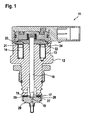
- FIG. 1 shows a schematic view of a pressure control valve in longitudinal section to illustrate the operation of the pressure control valve.
- FIG. 2 is, also in longitudinal section, the pressure control valve only shown with the parts that are important for the interaction with schematically drawn measuring systems for detecting a force and a path.
- FIG. 1 is a longitudinal section through a schematic representation of a pressure control valve 11 is shown, which may be arranged on a fuel accumulator not shown in the figure.
- the pressure regulating valve 11 has a housing 12, in which an electromagnet 13 is arranged with a coil winding 14.
- the coil winding 14 is embedded in soft magnetic material.
- an anchor bolt 16 of the electromagnet 13 which at its free end as a valve member 17 against a Closing element 18 expresses which closing element 18 in turn is supported on a valve seat 19.
- a radially extending anchor plate 21 is mounted, which is spaced with a flat bottom 22 to an opposite planar top 23 of the housing 12 by an air gap 24, which does not stand out graphically due to its small dimensions.
- the air gap 24 is set in the pressure control valve 11 by the axial height of a dial 26 which is arranged between a reference surface 27 of the housing 12 and an opposite bearing surface 28 of a valve seat body 29.
- pressure control valve 11 whose from the FIG. 1 Parts taken over here are not named again, is provided with a, with the anchor bolt 16 coupled force measuring system 31 and having a positioning pin 32 having Wegmeßsystem 33 which is shown only schematically and with a distance 34 between the reference surface 27 and an end face 36 of the valve member 17 is determined.
- the solenoid 13 is acted upon by a current corresponding to the nominal operating point of the pressure regulating valve 11.
- the anchor bolt 16 is displaced in the stationarily fixed housing 12 against the force caused by the energization of the electromagnet 13 until a predetermined opposing force with which the pressure regulating valve 11 is to close at the nominal operating point is reached.
- This force is controllable by the force measuring system 31 with high accuracy.
- the aforementioned displacement of the anchor bolt 16 is effected by the positioning pin 32 of the position measuring system 33, which bears against the end face 36 of the valve member 17.
- the axial distance 34 between the end face 36 of the valve member 17 and the reference surface 27 of the housing 12 of the pressure regulating valve 11 is measured at nominal working point of the pressure control valve 11 by the measuring system 33 with high accuracy.
Landscapes
- Engineering & Computer Science (AREA)
- Chemical & Material Sciences (AREA)
- Combustion & Propulsion (AREA)
- Mechanical Engineering (AREA)
- General Engineering & Computer Science (AREA)
- Fuel-Injection Apparatus (AREA)
- Magnetically Actuated Valves (AREA)
- Fluid-Pressure Circuits (AREA)
- Control Of Fluid Pressure (AREA)
Description
- Die Erfindung bezieht sich auf eine Anordnung zur Einstellung der_Schließkraft eines Druckregelventil mit einem Elektromagneten und einem beweglichen Anker, das insbesondere Verwendung findet in einem Kraftstoffeinspritzsystem für Brennkraftmaschinen zur Regelung eines Drucks in einem Kraftstoffspeicher.
- Elektromagnete mit beweglichem Anker werden außerdem als Aktoren in vielfältigen Anwendungen benutzt.
- Aus der
EP-A-1 065 372 ist ein Druckregelventil mit einem axial verschiebbaren. Ventilglied bekannt, das auf ein Schließelement wirkt, wobei das Ventilglied Teil eines Ankerbolzens eines Elektromagneten bildet. Zur Kalibrierung des Druckregelventils dient eine Einstellscheibe mit vorgebbarer Dicke. - Druckregelventile sind in vielfältigen Ausführungen bekannt. Das Druckregelventil dient zur Regelung des Drucks in einem Kraftstoffspeicher, mit dem es über einen Zulauf verbunden ist. Das Druckregelventil weist ein in einer Bohrung axial verschiebbar geführtes kolbenförmiges Ventilglied auf, das sich gegen eine Kraft, die vorzugsweise durch den Strom im Elektromagneten auf das Ventilglied wirkt, bewegen kann. Die Kraft wirkt in Schließrichtung, so dass das Ventilglied auf ein Schließelement des Druckregelventils gedrückt und gegen einen Ventilsitz gepresst wird. Das Ventilglied bildet einen Ankerbolzen eines Elektromagneten, der zur Kraftsteuerung bestrombar ist.
- Durch die Bestromung entsteht ein magnetisches Feld, das den Anker des Elektromagneten durchdringt, wodurch eine magnetische Kraft auf den Ankerbolzen wirkt. Das Ventilglied drückt das Schließelement mit dieser Kraft gegen den Ventilsitz.
- Wenn die durch den hydraulischen Druck des Kraftstoffs erzeugte Kraft die Schließkraft, die über das Ventilglied auf das Schließelement ausgeübt wird, überschreitet, wird das Schließelement vom Ventilsitz abgehoben. In diesem Fall fließt Kraftstoff aus dem Kraftstoffspeicher durch den Zulauf über das geöffnete Druckregelventil in einen Entlastungsraum ab.
- Bei der Einstellung eines höheren Drucks im Kraftstoffspeicher wird der Strom im Elektromagneten vergrößert, so dass die Schließkraft erhöht wird und somit das Schließelement erst bei einem höheren Druck im Kraftstoffspeicher vom Ventilsitz abhebt und Kraftstoff aus dem Kraftstoffspeicher in den Entlastungsraum abfließen kann.
- Die Regulierung des Drucks in dem Kraftstoffspeicher erfolgt über die Einstellung des Stroms in der Spule des Elektromagneten. Der tatsächliche Druck hängt somit von den Kenngrößen des Elektromagneten ab. Zu diesen gehören außer den elektromagnetischen Parametern auch die geometrischen Abmessungen. Von besonderer Bedeutung ist der Luftspalt zwischen dem beweglichen Anker und dem festen Ventilgehäuse, in dem sich die Spule des Elektromagneten befindet. Der Luftspalt wird durch die Bauteilgeometrie festgelegt.
- Um den Druck präzise einstellen zu können, bzw. ein präzises Druckintervall regeln zu können, müssen die Bauteile genau aneinander angepasst sein. Die notwendigen Fertigungstoleranzen sind entsprechend klein, was einen erheblichen Montage- und damit Kostenaufwand bedeutet.
- Die Aufgabe der Erfindung ist es, das aus dem Stand der Technik bekannte Druckregelventil derart weiterzubilden, dass die Einstellung der Schließkraft des Ventils in vormontiertem Zustand in präziser Weise erfolgen kann.
- Die Aufgabe wird erfindungsgemäß durch die Merkmale des Anspruchs 1 gelöst. Der Abstand zwischen Anker und Ventilgehäuse ist bestimmend für die Durchdringung des Ankers von den magnetischen Feldlinien und dementsprechend für die magnetische Kraft, die von dem Anker übertragen werden kann und zur Schließkraft des Druckregelventils führt. Die Erfassung dieses Abstands erfolgt erfindungsgemäß durch die Messung einer von dem Magnetkreis erzeugten Kraft und aus einer Wegmessung bei einer gleichzeitig stattfindenden Positionierung des Ventilglieds. Diese beiden physikalische Größen lassen sich sehr genau erfassen und erlauben eine präzise Einstellung des Druckregelventils ohne Einflüsse von mechanischen Toleranzen und den Stoffeigenschaften am Elektromagneten.
- Durch die in den Unteransprüchen aufgeführten Maßnahmen sind vorteilhafte Weiterbildungen und Verbesserungen des im Anspruch 1 angegebenen Druckregelventils möglich.
- Gemäß vorteilhafter Ausgestaltung erfolgt die Bestromung des Elektromagneten mit einem dem Nennarbeitspunkt des Druckregelventils entsprechendem Strom, so dass hier Verhältnisse vorliegen, wie sie auch später im Betrieb des Druckregelventils auftreten.
- Auch vorteilhaft ist, dass die Bestromung des Elektromagneten geregelt erfolgt, so dass Rückkopplungseffekte auf die Messungen, insbesondere bei der Positionierung des Ventilgliedes, vermieden werden und ständig der dem Nennarbeitspunkt des Druckregelventil entsprechende Strom vorliegt.
- Weitere vorteilhafte Ausgestaltungen gehen aus der nachfolgenden Beschreibung sowie den Ansprüchen hervor.
- Ein Ausführungsbeispiel der Erfindung ist in der Zeichnung dargestellt und in der Figurenbeschreibung näher erläutert.
Figur 1 zeigt eine schematische Ansicht eines Druckregelventils im Längsschnitt zur Verdeutlichung der Arbeitsweise des Druckregelventils. In derFigur 2 ist, ebenfalls im Längsschnitt, das Druckregelventil nur noch mit den Teilen dargestellt, die für das Zusammenwirken mit schematisiert eingezeichneten Meßsystemen zur Erfassung einer Kraft und eines Weges von Bedeutung sind. - In
Figur 1 ist ein Längsschnitt durch eine schematische Darstellung eines Druckregelventils 11 gezeigt, das an einem in der Figur nicht dargestelltem Kraftstoffspeicher angeordnet sein kann. - Das Druckregelventil 11 weist ein Gehäuse 12 auf, in dem ein Elektromagnet 13 mit einer Spulenwicklung 14 angeordnet ist. Die Spulenwicklung 14 ist in weichmagnetisches Material eingebettet.
- In einer axialen Ausnehmung des Gehäuses 12 befindet sich ein Ankerbolzen 16 des Elektromagneten 13, welcher an seinem freien Ende als Ventilglied 17 gegen ein Schließelement 18 drückt, welches Schließelement 18 sich wiederum auf einem Ventilsitz 19 abstützt.
- An dem anderen Ende des axial gerichteten Ankerbolzens 16 ist eine radial verlaufende Ankerplatte 21 angebracht, die mit einer planen Unterseite 22 zu einer gegenüberliegenden planen Oberseite 23 des Gehäuses 12 durch einen Luftspalt 24, der aufgrund seiner geringen Ausmaße zeichnerisch nicht hervortritt, beabstandet ist. Der Luftspalt 24 wird bei dem Druckregelventil 11 durch die axiale Höhe einer Einstellscheibe 26, die zwischen einer Referenzfläche 27 des Gehäuses 12 und einer gegenüberliegenden Auflagefläche 28 eines Ventilsitzkörpers 29 angeordnet ist, eingestellt.
- Durch Bestromung des Elektromagneten 13 werden die Ankerplatte 21 und der Ankerbolzen 16 von magnetischen Flußlinien durchdrungen, wodurch eine magnetische Kraft wirkt, die das Ventilglied 17 gegen das Schließelement 18 sowie den Ventilsitz 19 drückt. Die Größe dieser Kraft ist abhängig von der Größe des Luftspaltes 24.
- Das in der
Figur 2 im Längsschnitt dargestellte Druckregelventil 11, dessen von derFigur 1 übernommenen Teile hier nicht nochmals benannt werden, ist mit einem, mit dem Ankerbolzen 16 gekoppelten Kraftmeßsystem 31 und mit einem Positionierstift 32 aufweisenden Wegmeßsystem 33 versehen, der nur schematisiert dargestellt ist und mit dem ein Abstand 34 zwischen der Referenzfläche 27 und einer Stirnfläche 36 des Ventilgliedes 17 ermittelt wird. - Zur Ermittlung des Abstandes 34 für die Dimensionierung der axialen Höhe der noch einzufügenden Einstellscheibe 26, die in der
Figur 1 gezeigt ist, wird der Elektromagnet 13 mit einem Strom beaufschlagt, der dem Nennarbeitspunkt des Druckregelventils 11 entspricht. Aus diesem Grundzustand heraus wird in dem ortsfest fixierten Gehäuse 12 der Ankerbolzen 16 solange gegen die durch die Bestromung des Elektromagneten 13 hervorgerufenen Kraft verschoben, bis eine vorgegebene Gegenkraft, mit der das Druckregelventil 11 im Nennarbeitspunkt schließen soll, erreicht ist. Diese Kraft ist durch das Kraftmeßsystem 31 mit hoher Genauigkeit kontrollierbar. - Die vorgenannte Verschiebung des Ankerbolzens 16 erfolgt durch den Positionierstift 32 des Wegmeßsystems 33, der an Stirnfläche 36 des Ventilgliedes 17 anliegt.
- Mit dem Erreichen der durch das Kraftmeßsystem 31 kontrollierten vorgegebenen Gegenkraft wird im Nennarbeitspunkt des Druckregelventils 11 durch das Wegmeßsystem 33 mit hoher Genauigkeit der axiale Abstand 34 zwischen der Stirnfläche 36 des Ventilgliedes 17 und der Referenzfläche 27 des Gehäuses 12 des Druckregelventils 11 gemessen.
- Aufgrund der Präzisionsmessungen des Wegmeßsystems 33 und der dieses steuernde Kraftmeßsystems 31 sind die Voraussetzungen für eine hochgenaue Ermittlung des Abstandes 34 und der damit ableitbaren axialen Höhe der Einstellscheibe 26 gegeben, so dass damit der von dem Druckregelventil 11 überwachte Druck des Kraftstoffspeichers in engen Grenzen einhaltbar ist.
Claims (3)
- Anordnung zur Einstellung der Schließkraft eines Druckregelventils, insbesondere für ein Kraftstoffeinspritzsystem für Brennkraftmaschinen zur Regelung des Drucks in einem Kraftstoffspeicher, mit einem, in einer Ausnehmung eines Gehäuses (12) des Druckregelventils (11) axial verschiebbar geführten Ventilglied (17), das auf ein Schließelement (18) wirkt, welches gegen einen Ventilsitz (19) pressbar ist, wobei das Ventilglied (17) Teil eines Ankerbolzens (16) eines Elektromagneten (13) bildet, der bestrombar ist und zur Einstellung des Druckregelventils eine Einstellscheibe (26) verwendet wird, dadurch gekennzeichnet, dass die Positionierung des Ventilgliedes (17) durch ein Wegmeßsystem (33) und die dabei einzuhaltende Gegenkraft durch ein Kraftmeßsystem (31) erfasst wird und durch das Wegmeßsystem (33) der Abstand (34) zwischen dem Ventilglied (17) und einer Referenzfläche (27) des Gehäuses (12) bei einer vorgegebenen Bestromung des Elektromagneten (13) und einer gleichzeitigen Positionierung des Ventilglieds (17) bis zu einer vorgegebenen Gegenkraft zur Dimensionierung der Einstellscheibe (26) für > das Druckregelventil ermittelt wird, über die ein die Stellkraft des Druckregelventils (11) bestimmende Luftspalt (24) eingestellt wird.
- Anordnung nach Anspruch 1, dadurch gekennzeichnet, dass die vorgegebene Bestromung des Elektromagneten (13) mit einem, dem Nennarbeitspunkt des Druckregelventils (11) entsprechendem Strom erfolgt.
- Anordnung nach Anspruch 2, dadurch gekennzeichnet, dass die Bestromung geregelt erfolgt.
Applications Claiming Priority (2)
| Application Number | Priority Date | Filing Date | Title |
|---|---|---|---|
| DE102004062004A DE102004062004A1 (de) | 2004-12-23 | 2004-12-23 | Druckregelventil |
| PCT/EP2005/056150 WO2006069860A1 (de) | 2004-12-23 | 2005-11-22 | Druckregelventil |
Publications (2)
| Publication Number | Publication Date |
|---|---|
| EP1831541A1 EP1831541A1 (de) | 2007-09-12 |
| EP1831541B1 true EP1831541B1 (de) | 2009-10-28 |
Family
ID=35788893
Family Applications (1)
| Application Number | Title | Priority Date | Filing Date |
|---|---|---|---|
| EP05817180A Expired - Lifetime EP1831541B1 (de) | 2004-12-23 | 2005-11-22 | Druckregelventil |
Country Status (6)
| Country | Link |
|---|---|
| US (1) | US7721712B2 (de) |
| EP (1) | EP1831541B1 (de) |
| JP (1) | JP4532565B2 (de) |
| AT (1) | ATE447105T1 (de) |
| DE (2) | DE102004062004A1 (de) |
| WO (1) | WO2006069860A1 (de) |
Families Citing this family (6)
| Publication number | Priority date | Publication date | Assignee | Title |
|---|---|---|---|---|
| DE102007011654A1 (de) * | 2007-03-09 | 2008-09-11 | Continental Automotive Gmbh | Verfahren und Vorrichtung zur Volumenstromregelung eines Einspritzsystems |
| DE102009047649A1 (de) * | 2009-12-08 | 2011-06-09 | Robert Bosch Gmbh | Druckregelventil zur Regelung des Drucks in einem Hochdruck-Kraftstoffspeicher einer Brennkraftmaschine |
| FR2973076A1 (fr) * | 2011-03-25 | 2012-09-28 | Bosch Gmbh Robert | Regulateur de pression, dispositif d'injection diesel comportant un tel regulateur, moteur diesel comportant un tel dispositif d'injection et vehicule comportant un tel moteur |
| EP2535554A1 (de) | 2011-06-15 | 2012-12-19 | Delphi Technologies Holding S.à.r.l. | Elektroventil zur Common-Rail-Entladung |
| FR2999658A1 (fr) * | 2012-12-18 | 2014-06-20 | Delphi Technologies Holding | Vanne haute pression |
| FR3030638B1 (fr) * | 2014-12-23 | 2017-01-13 | Bosch Gmbh Robert | Regulateur de pression pour une rampe haute-pression de systeme d'injection de carburant |
Family Cites Families (10)
| Publication number | Priority date | Publication date | Assignee | Title |
|---|---|---|---|---|
| IT1296144B1 (it) * | 1997-11-18 | 1999-06-09 | Elasis Sistema Ricerca Fiat | Valvola di dosaggio registrabile per un iniettore di combustibile per motori a combustione interna. |
| DE19905722A1 (de) * | 1998-02-24 | 1999-08-26 | Hoerbiger Ventilwerke Gmbh | Gasventil |
| IT1308779B1 (it) * | 1999-07-02 | 2002-01-10 | Elasis Sistema Ricerca Fiat | Dispositivo di regolazione della pressione di mandata di una pompa,adesempio per l'alimentazione di combustibile ad un motore a combustione |
| DE10107115B4 (de) * | 2001-02-14 | 2004-09-30 | Robert Bosch Gmbh | Drucksteuerventil |
| JP2003097749A (ja) * | 2001-09-26 | 2003-04-03 | Denso Corp | 電磁式流体制御装置 |
| DE10214084A1 (de) * | 2002-03-28 | 2003-10-30 | Bosch Gmbh Robert | Einstellbares Druckregelventil für Kraftstoffeinspritzsysteme |
| US7099136B2 (en) * | 2002-10-23 | 2006-08-29 | Seale Joseph B | State space control of solenoids |
| DE10334615A1 (de) * | 2003-07-29 | 2005-02-17 | Robert Bosch Gmbh | Druckregelventil für Speicherkraftstoffeinspritzsystem |
| JP2005291411A (ja) * | 2004-04-01 | 2005-10-20 | Toyoda Mach Works Ltd | 過流防止弁 |
| US7441546B2 (en) * | 2005-07-28 | 2008-10-28 | Denso Corporation | Valve apparatus |
-
2004
- 2004-12-23 DE DE102004062004A patent/DE102004062004A1/de not_active Withdrawn
-
2005
- 2005-11-22 WO PCT/EP2005/056150 patent/WO2006069860A1/de not_active Ceased
- 2005-11-22 US US11/722,224 patent/US7721712B2/en active Active
- 2005-11-22 EP EP05817180A patent/EP1831541B1/de not_active Expired - Lifetime
- 2005-11-22 AT AT05817180T patent/ATE447105T1/de not_active IP Right Cessation
- 2005-11-22 JP JP2007547427A patent/JP4532565B2/ja not_active Expired - Lifetime
- 2005-11-22 DE DE502005008427T patent/DE502005008427D1/de not_active Expired - Lifetime
Also Published As
| Publication number | Publication date |
|---|---|
| DE102004062004A1 (de) | 2006-07-13 |
| US7721712B2 (en) | 2010-05-25 |
| DE502005008427D1 (de) | 2009-12-10 |
| ATE447105T1 (de) | 2009-11-15 |
| EP1831541A1 (de) | 2007-09-12 |
| JP4532565B2 (ja) | 2010-08-25 |
| JP2008525697A (ja) | 2008-07-17 |
| US20100018501A1 (en) | 2010-01-28 |
| WO2006069860A1 (de) | 2006-07-06 |
Similar Documents
| Publication | Publication Date | Title |
|---|---|---|
| EP2222524B1 (de) | Druckregelventil | |
| EP1266135B1 (de) | Magnetventil zur steuerung eines einspritzventils einer brennkraftmaschine | |
| DE602005002126T2 (de) | Verstellbares Dosierservoventil eines Einspritzventils | |
| DE102007047422A1 (de) | Elektromagnetisches Druckventil | |
| WO2019037924A1 (de) | Proportionalventil zum steuern eines gasförmigen mediums | |
| EP2558757B1 (de) | Stromregelventil | |
| WO2012163892A2 (de) | Einlassventil für eine fluidpumpe und montageverfahren für ein einlassventil für eine fluidpumpe | |
| DE102021000617A1 (de) | Injektor zum Einblasen eines Gases in einen Brennraum oder in ein Saugrohr eines Kraftfahrzeuges | |
| EP3077658B1 (de) | Elektromagnetisch betätigtes ventil | |
| WO2003002868A1 (de) | Magnetventil zur steuerung eines einspritzventils einer brennkraftmaschine | |
| EP2409012A1 (de) | Vorrichtung zum einspritzen von kraftstoff in den brennraum einer brennkraftmaschine | |
| WO2006069860A1 (de) | Druckregelventil | |
| EP3714169A1 (de) | Strahlpumpeneinheit mit einem dosierventil zum steuern eines gasförmigen mediums | |
| EP2064437B1 (de) | Injektor zum einspritzen von kraftstoff | |
| WO2016034402A1 (de) | Elektromagnetisch betätigbares proportionalventil | |
| EP2276922B1 (de) | Kraftstoffinjektor mit magnetventil | |
| EP1744054B1 (de) | Aktive Ankerhubeinstellung bei Kraftstoffinjektoren | |
| WO2018202345A1 (de) | Dosiervorrichtung zum steuern eines gasförmigen mediums | |
| EP1837567B1 (de) | Sicherheitsventil zum automatischen Absperren von Gasleitungen | |
| EP2357353B1 (de) | Verfahren zur Erkennung des Schließzeitpunktes eines Einspritzventilgliedes in einem Kraftstoffeinspritzventil sowie Kraftstoffeinspritzventil | |
| WO2018219527A1 (de) | Proportionalventil zum steuern eines gasförmigen mediums | |
| DE102012205342A1 (de) | Hochdruckpumpe für ein Kraftstoffeinspritzsystem | |
| WO2008084112A1 (de) | Hochdruckdieselventil und geeigneter magnet | |
| DE20220654U1 (de) | Proportionalventil | |
| WO2019052717A1 (de) | Dosiervorrichtung zum steuern eines gasförmigen mediums |
Legal Events
| Date | Code | Title | Description |
|---|---|---|---|
| PUAI | Public reference made under article 153(3) epc to a published international application that has entered the european phase |
Free format text: ORIGINAL CODE: 0009012 |
|
| 17P | Request for examination filed |
Effective date: 20070723 |
|
| AK | Designated contracting states |
Kind code of ref document: A1 Designated state(s): AT BE BG CH CY CZ DE DK EE ES FI FR GB GR HU IE IS IT LI LT LU LV MC NL PL PT RO SE SI SK TR |
|
| 17Q | First examination report despatched |
Effective date: 20071106 |
|
| DAX | Request for extension of the european patent (deleted) | ||
| GRAP | Despatch of communication of intention to grant a patent |
Free format text: ORIGINAL CODE: EPIDOSNIGR1 |
|
| GRAS | Grant fee paid |
Free format text: ORIGINAL CODE: EPIDOSNIGR3 |
|
| GRAA | (expected) grant |
Free format text: ORIGINAL CODE: 0009210 |
|
| AK | Designated contracting states |
Kind code of ref document: B1 Designated state(s): AT BE BG CH CY CZ DE DK EE ES FI FR GB GR HU IE IS IT LI LT LU LV MC NL PL PT RO SE SI SK TR |
|
| REG | Reference to a national code |
Ref country code: GB Ref legal event code: FG4D Free format text: NOT ENGLISH |
|
| REG | Reference to a national code |
Ref country code: CH Ref legal event code: EP |
|
| REG | Reference to a national code |
Ref country code: IE Ref legal event code: FG4D |
|
| REF | Corresponds to: |
Ref document number: 502005008427 Country of ref document: DE Date of ref document: 20091210 Kind code of ref document: P |
|
| LTIE | Lt: invalidation of european patent or patent extension |
Effective date: 20091028 |
|
| NLV1 | Nl: lapsed or annulled due to failure to fulfill the requirements of art. 29p and 29m of the patents act | ||
| PG25 | Lapsed in a contracting state [announced via postgrant information from national office to epo] |
Ref country code: SE Free format text: LAPSE BECAUSE OF FAILURE TO SUBMIT A TRANSLATION OF THE DESCRIPTION OR TO PAY THE FEE WITHIN THE PRESCRIBED TIME-LIMIT Effective date: 20091028 Ref country code: PT Free format text: LAPSE BECAUSE OF FAILURE TO SUBMIT A TRANSLATION OF THE DESCRIPTION OR TO PAY THE FEE WITHIN THE PRESCRIBED TIME-LIMIT Effective date: 20100301 Ref country code: LT Free format text: LAPSE BECAUSE OF FAILURE TO SUBMIT A TRANSLATION OF THE DESCRIPTION OR TO PAY THE FEE WITHIN THE PRESCRIBED TIME-LIMIT Effective date: 20091028 Ref country code: ES Free format text: LAPSE BECAUSE OF FAILURE TO SUBMIT A TRANSLATION OF THE DESCRIPTION OR TO PAY THE FEE WITHIN THE PRESCRIBED TIME-LIMIT Effective date: 20100208 Ref country code: FI Free format text: LAPSE BECAUSE OF FAILURE TO SUBMIT A TRANSLATION OF THE DESCRIPTION OR TO PAY THE FEE WITHIN THE PRESCRIBED TIME-LIMIT Effective date: 20091028 Ref country code: IS Free format text: LAPSE BECAUSE OF FAILURE TO SUBMIT A TRANSLATION OF THE DESCRIPTION OR TO PAY THE FEE WITHIN THE PRESCRIBED TIME-LIMIT Effective date: 20100228 |
|
| REG | Reference to a national code |
Ref country code: IE Ref legal event code: FD4D |
|
| BERE | Be: lapsed |
Owner name: ROBERT BOSCH G.M.B.H. Effective date: 20091130 |
|
| PG25 | Lapsed in a contracting state [announced via postgrant information from national office to epo] |
Ref country code: LV Free format text: LAPSE BECAUSE OF FAILURE TO SUBMIT A TRANSLATION OF THE DESCRIPTION OR TO PAY THE FEE WITHIN THE PRESCRIBED TIME-LIMIT Effective date: 20091028 Ref country code: PL Free format text: LAPSE BECAUSE OF FAILURE TO SUBMIT A TRANSLATION OF THE DESCRIPTION OR TO PAY THE FEE WITHIN THE PRESCRIBED TIME-LIMIT Effective date: 20091028 Ref country code: CY Free format text: LAPSE BECAUSE OF FAILURE TO SUBMIT A TRANSLATION OF THE DESCRIPTION OR TO PAY THE FEE WITHIN THE PRESCRIBED TIME-LIMIT Effective date: 20091028 Ref country code: SI Free format text: LAPSE BECAUSE OF FAILURE TO SUBMIT A TRANSLATION OF THE DESCRIPTION OR TO PAY THE FEE WITHIN THE PRESCRIBED TIME-LIMIT Effective date: 20091028 |
|
| PG25 | Lapsed in a contracting state [announced via postgrant information from national office to epo] |
Ref country code: MC Free format text: LAPSE BECAUSE OF NON-PAYMENT OF DUE FEES Effective date: 20091130 |
|
| REG | Reference to a national code |
Ref country code: CH Ref legal event code: PL |
|
| PG25 | Lapsed in a contracting state [announced via postgrant information from national office to epo] |
Ref country code: IE Free format text: LAPSE BECAUSE OF FAILURE TO SUBMIT A TRANSLATION OF THE DESCRIPTION OR TO PAY THE FEE WITHIN THE PRESCRIBED TIME-LIMIT Effective date: 20091028 Ref country code: EE Free format text: LAPSE BECAUSE OF FAILURE TO SUBMIT A TRANSLATION OF THE DESCRIPTION OR TO PAY THE FEE WITHIN THE PRESCRIBED TIME-LIMIT Effective date: 20091028 Ref country code: BG Free format text: LAPSE BECAUSE OF FAILURE TO SUBMIT A TRANSLATION OF THE DESCRIPTION OR TO PAY THE FEE WITHIN THE PRESCRIBED TIME-LIMIT Effective date: 20100128 Ref country code: RO Free format text: LAPSE BECAUSE OF FAILURE TO SUBMIT A TRANSLATION OF THE DESCRIPTION OR TO PAY THE FEE WITHIN THE PRESCRIBED TIME-LIMIT Effective date: 20091028 Ref country code: DK Free format text: LAPSE BECAUSE OF FAILURE TO SUBMIT A TRANSLATION OF THE DESCRIPTION OR TO PAY THE FEE WITHIN THE PRESCRIBED TIME-LIMIT Effective date: 20091028 |
|
| PG25 | Lapsed in a contracting state [announced via postgrant information from national office to epo] |
Ref country code: SK Free format text: LAPSE BECAUSE OF FAILURE TO SUBMIT A TRANSLATION OF THE DESCRIPTION OR TO PAY THE FEE WITHIN THE PRESCRIBED TIME-LIMIT Effective date: 20091028 Ref country code: CZ Free format text: LAPSE BECAUSE OF FAILURE TO SUBMIT A TRANSLATION OF THE DESCRIPTION OR TO PAY THE FEE WITHIN THE PRESCRIBED TIME-LIMIT Effective date: 20091028 |
|
| PLBE | No opposition filed within time limit |
Free format text: ORIGINAL CODE: 0009261 |
|
| STAA | Information on the status of an ep patent application or granted ep patent |
Free format text: STATUS: NO OPPOSITION FILED WITHIN TIME LIMIT |
|
| 26N | No opposition filed |
Effective date: 20100729 |
|
| PG25 | Lapsed in a contracting state [announced via postgrant information from national office to epo] |
Ref country code: CH Free format text: LAPSE BECAUSE OF NON-PAYMENT OF DUE FEES Effective date: 20091130 Ref country code: GR Free format text: LAPSE BECAUSE OF FAILURE TO SUBMIT A TRANSLATION OF THE DESCRIPTION OR TO PAY THE FEE WITHIN THE PRESCRIBED TIME-LIMIT Effective date: 20100129 Ref country code: LI Free format text: LAPSE BECAUSE OF NON-PAYMENT OF DUE FEES Effective date: 20091130 Ref country code: BE Free format text: LAPSE BECAUSE OF NON-PAYMENT OF DUE FEES Effective date: 20091130 |
|
| PG25 | Lapsed in a contracting state [announced via postgrant information from national office to epo] |
Ref country code: AT Free format text: LAPSE BECAUSE OF NON-PAYMENT OF DUE FEES Effective date: 20091122 |
|
| PG25 | Lapsed in a contracting state [announced via postgrant information from national office to epo] |
Ref country code: LU Free format text: LAPSE BECAUSE OF NON-PAYMENT OF DUE FEES Effective date: 20091122 |
|
| PG25 | Lapsed in a contracting state [announced via postgrant information from national office to epo] |
Ref country code: HU Free format text: LAPSE BECAUSE OF FAILURE TO SUBMIT A TRANSLATION OF THE DESCRIPTION OR TO PAY THE FEE WITHIN THE PRESCRIBED TIME-LIMIT Effective date: 20100429 |
|
| PG25 | Lapsed in a contracting state [announced via postgrant information from national office to epo] |
Ref country code: TR Free format text: LAPSE BECAUSE OF FAILURE TO SUBMIT A TRANSLATION OF THE DESCRIPTION OR TO PAY THE FEE WITHIN THE PRESCRIBED TIME-LIMIT Effective date: 20091028 |
|
| PG25 | Lapsed in a contracting state [announced via postgrant information from national office to epo] |
Ref country code: NL Free format text: LAPSE BECAUSE OF FAILURE TO SUBMIT A TRANSLATION OF THE DESCRIPTION OR TO PAY THE FEE WITHIN THE PRESCRIBED TIME-LIMIT Effective date: 20091028 |
|
| PGFP | Annual fee paid to national office [announced via postgrant information from national office to epo] |
Ref country code: GB Payment date: 20131122 Year of fee payment: 9 |
|
| PGFP | Annual fee paid to national office [announced via postgrant information from national office to epo] |
Ref country code: IT Payment date: 20131125 Year of fee payment: 9 |
|
| GBPC | Gb: european patent ceased through non-payment of renewal fee |
Effective date: 20141122 |
|
| PG25 | Lapsed in a contracting state [announced via postgrant information from national office to epo] |
Ref country code: GB Free format text: LAPSE BECAUSE OF NON-PAYMENT OF DUE FEES Effective date: 20141122 |
|
| REG | Reference to a national code |
Ref country code: FR Ref legal event code: PLFP Year of fee payment: 11 |
|
| PG25 | Lapsed in a contracting state [announced via postgrant information from national office to epo] |
Ref country code: IT Free format text: LAPSE BECAUSE OF NON-PAYMENT OF DUE FEES Effective date: 20141122 |
|
| REG | Reference to a national code |
Ref country code: FR Ref legal event code: PLFP Year of fee payment: 12 |
|
| REG | Reference to a national code |
Ref country code: FR Ref legal event code: PLFP Year of fee payment: 13 |
|
| PGFP | Annual fee paid to national office [announced via postgrant information from national office to epo] |
Ref country code: FR Payment date: 20241120 Year of fee payment: 20 |
|
| PGFP | Annual fee paid to national office [announced via postgrant information from national office to epo] |
Ref country code: DE Payment date: 20250122 Year of fee payment: 20 |
|
| REG | Reference to a national code |
Ref country code: DE Ref legal event code: R071 Ref document number: 502005008427 Country of ref document: DE |