EP1831090B1 - Device and method for closing the tail end of logs of web material and relative logs obtained therewith - Google Patents
Device and method for closing the tail end of logs of web material and relative logs obtained therewith Download PDFInfo
- Publication number
- EP1831090B1 EP1831090B1 EP05823561A EP05823561A EP1831090B1 EP 1831090 B1 EP1831090 B1 EP 1831090B1 EP 05823561 A EP05823561 A EP 05823561A EP 05823561 A EP05823561 A EP 05823561A EP 1831090 B1 EP1831090 B1 EP 1831090B1
- Authority
- EP
- European Patent Office
- Prior art keywords
- log
- adhesive
- web material
- tail end
- folded
- Prior art date
- Legal status (The legal status is an assumption and is not a legal conclusion. Google has not performed a legal analysis and makes no representation as to the accuracy of the status listed.)
- Not-in-force
Links
Images


Classifications
-
- B—PERFORMING OPERATIONS; TRANSPORTING
- B65—CONVEYING; PACKING; STORING; HANDLING THIN OR FILAMENTARY MATERIAL
- B65H—HANDLING THIN OR FILAMENTARY MATERIAL, e.g. SHEETS, WEBS, CABLES
- B65H19/00—Changing the web roll
- B65H19/22—Changing the web roll in winding mechanisms or in connection with winding operations
- B65H19/29—Securing the trailing end of the wound web to the web roll
-
- B—PERFORMING OPERATIONS; TRANSPORTING
- B65—CONVEYING; PACKING; STORING; HANDLING THIN OR FILAMENTARY MATERIAL
- B65H—HANDLING THIN OR FILAMENTARY MATERIAL, e.g. SHEETS, WEBS, CABLES
- B65H2301/00—Handling processes for sheets or webs
- B65H2301/40—Type of handling process
- B65H2301/41—Winding, unwinding
- B65H2301/414—Winding
- B65H2301/4144—Finishing winding process
- B65H2301/41441—Finishing winding process and blocking outer layers against falling apart
- B65H2301/41442—Specified by the sealing medium sealing used
- B65H2301/414421—Glue or hot-melt
-
- B—PERFORMING OPERATIONS; TRANSPORTING
- B65—CONVEYING; PACKING; STORING; HANDLING THIN OR FILAMENTARY MATERIAL
- B65H—HANDLING THIN OR FILAMENTARY MATERIAL, e.g. SHEETS, WEBS, CABLES
- B65H2301/00—Handling processes for sheets or webs
- B65H2301/40—Type of handling process
- B65H2301/41—Winding, unwinding
- B65H2301/414—Winding
- B65H2301/4144—Finishing winding process
- B65H2301/41441—Finishing winding process and blocking outer layers against falling apart
- B65H2301/41442—Specified by the sealing medium sealing used
- B65H2301/414428—Folding of trailing end
-
- B—PERFORMING OPERATIONS; TRANSPORTING
- B65—CONVEYING; PACKING; STORING; HANDLING THIN OR FILAMENTARY MATERIAL
- B65H—HANDLING THIN OR FILAMENTARY MATERIAL, e.g. SHEETS, WEBS, CABLES
- B65H2403/00—Power transmission; Driving means
- B65H2403/90—Machine drive
- B65H2403/94—Other features of machine drive
- B65H2403/942—Bidirectional powered handling device
-
- Y—GENERAL TAGGING OF NEW TECHNOLOGICAL DEVELOPMENTS; GENERAL TAGGING OF CROSS-SECTIONAL TECHNOLOGIES SPANNING OVER SEVERAL SECTIONS OF THE IPC; TECHNICAL SUBJECTS COVERED BY FORMER USPC CROSS-REFERENCE ART COLLECTIONS [XRACs] AND DIGESTS
- Y10—TECHNICAL SUBJECTS COVERED BY FORMER USPC
- Y10T—TECHNICAL SUBJECTS COVERED BY FORMER US CLASSIFICATION
- Y10T156/00—Adhesive bonding and miscellaneous chemical manufacture
- Y10T156/10—Methods of surface bonding and/or assembly therefor
- Y10T156/1002—Methods of surface bonding and/or assembly therefor with permanent bending or reshaping or surface deformation of self sustaining lamina
- Y10T156/1051—Methods of surface bonding and/or assembly therefor with permanent bending or reshaping or surface deformation of self sustaining lamina by folding
Definitions
- the present invention relates to improvements to methods and devices to close, by gluing or adhesion, the tail end of rolls or logs of wound web material, such as logs of tissue paper to produce kitchen towels, toilet paper or the like.
- a predetermined quantity of web material is wound into individual logs.
- the web material is usually delivered from reels of large diameter produced in paper mills.
- the logs of smaller diameter, which are produced in the rewinding machines, are optionally then divided into rolls of smaller axial length, i.e. of dimensions equivalent to the finished product that is subsequently packaged and distributed to the consumer.
- the loose tail end of the wound web material must be glued or in any case made to adhere to the log or roll in order to facilitate subsequent handling through the various production steps till final packaging. If this were not performed the logs could become accidentally unwound and obstruct the subsequent converting operations performed before they are packaged.
- the object of the present invention is to provide a device and a method for gluing the loose tail end of logs or rolls of web material, which on the one hand allow efficient gluing and on the other facilitate the subsequent step to open the roll by the final user.
- the object of a preferred embodiment of the invention is to produce a method and a device which make it possible to obtain gluing with which subsequent opening of the loose end of the roll is facilitated, without tearing of the web material forming the first turn wound on the roll.
- a first aspect of the invention provides for a method to close the tail end of a log of web material using an adhesive, comprising the steps of: unwinding a portion of the web material from the log; applying the adhesive; rewinding the portion of web material to make the tail end adhere to the log.
- the tail end is folded before being rewound on the log thereby forming a fold of web material, which forms a portion for gripping and detaching the web material from the roll at the time of use.
- This gripping and detaching area has a double thickness with respect to the web material, having been obtained by folding of the tail end and therefore has increased consistency and strength.
- a folded portion of web material is formed to define a double end to facilitate grip and opening the roll by the final user.
- the folded tail end forms a fold of web material, which projects beyond the adhesive when the tail end has been rewound on the log.
- the tail end can be folded outwards, i.e. so that the terminal edge of the web material is on the outer surface of the closed log. Nonetheless, according to the preferred embodiment of the invention, the tail end is folded on the inner surface of the unwound portion of the web material, so that the terminal edge of the tail end is positioned inside the last turn of web material wound on the log. This inward folding of the tail end further facilitates opening of the log, as the risk of the first turn of web material tearing due to incomplete detachment from the subsequent turn is reduced substantially.
- the adhesive which is used to close the loose end, preferably although not necessarily a liquid adhesive, is applied in proximity to the terminal edge of the tail end.
- the adhesive is applied in proximity to the terminal edge of said end, on the surface of the material, which, after rewinding of the tail portion of web material, comes into contact with the outer surface of the log.
- the adhesive it would also be possible for the adhesive to be applied, after having partially unwound a quantity of web material exceeding the length of one turn, to the outer surface of the log, i.e. to a portion of the web material still wound on the log. In this case, after folding the loose end, the web material is rewound to cover the adhesive applied to the back of the log.
- the adhesive is preferably applied as close as possible to the terminal edge of the loose end, i.e. as close as possible to the position that this edge takes after folding of the loose tail end.
- the adhesive is applied exactly corresponding to the terminal edge of the folded loose end, so that it projects in part on one side and in part on the other side with respect to the terminal edge of the end.
- the adhesive can be in the form of a double-sided adhesive tape, although it is preferable to use an adhesive in the form of liquid glue. If the adhesive is in liquid form, it can be picked up, in a per se known way, by a movable dispensing element, which picks up the liquid adhesive from a reservoir or container and applies it to the desired point on the surface of the web material. In a possible embodiment of the invention, the movable dispensing element is also used to perform folding of the tail end, in order to reduce the movable members required to perform the operations to close the tail end.
- the adhesive is preferable for the adhesive to be applied at a certain distance from the folding line of the loose tail end, in order to keep a portion of folded web material projecting from the gluing line, to facilitate grip it would also be possible to distribute glue or adhesive up to the folding line according to a continuous line or in stretches, due to the form of the dispenser or the operating mode thereof, as will be explained hereunder.
- the adhesive can be applied according to a continuous line, or according to a discontinuous line, or yet again also in one or two points close to the fold of the loose tail end, to leave stretches of material loose and easily gripped by the fingers of the user at the time the roll is opened, when it is used for the first time.
- the invention relates to a device for closing the tail end of logs of web material, comprising a system for unwinding a portion of web material from the log and a system for rewinding the tail end on the log after the adhesive has been applied, and a folding member to fold the tail end and form a fold of web material adjacent to the adhesive after the tail end has been rewound and made to adhere to the log.
- the invention also relates to a log of wound web material, with a tail end fastened by means of an adhesive to the surface of the log, wherein said tail end is folded and forms a fold defining a portion for gripping and detaching the folded end from the log. This portion has double thickness compared to the thickness of the base web material.
- a first embodiment of the invention is represented in side view and in axonometric view in Figures 1A to 2C .
- the device to close the tail end of the log R substantially comprises a supporting and rolling surface 3 on which the log R is fed in a per se known way, not shown, e.g. by a rotary butterfly distributor.
- a lower roller 5 Positioned in the final area of the supporting and rolling surface 3 is a lower roller 5 with an axis 5A located below said surface.
- the roller 5 has annular raised portions 5R (see in particular Figures 2A, 2B and 2C ), which project through profiles 3A, which define the supporting surface 3. In this way the surface of the roller 5 projects partially beyond the supporting surface 3 in order to come into contact with the log R.
- the assembly formed of the belts 9 and of the rollers 7, 10 can be supported in an adjustable way, to set the distance of the belts 9 with respect to the supporting surface 3, as a function of the diameter of the logs to be glued.
- the distance between the roller 7 with the belts 9 and the roller 5 is such that a log R can be inserted between these members, in contact with the annular raised portions 5R of the roller 5 and the belts 9. In this way it is possible to retain the log R in a controlled position and make it rotate in the desired direction to control opening and positioning of the tail end of said log, allowing the subsequent gluing operations.
- nozzles 11 aligned parallel to the axis of the rollers 5, 7 and 10 and oriented towards the surface of the log R when this comes to be positioned between the rollers 5 and 7.
- the supporting surface 3 is tilted downwards and is equipped with a series of suction holes 13 in connection with a suction box 15 below.
- a photocell 17 or another suitable sensor Positioned beyond the end area of the supporting surface 3 is a photocell 17 or another suitable sensor to detect in a per se known way the presence of the loose tail end unwound from the log R.
- a container 19 of adhesive in the form of a liquid glue inside which a movable applicator element can be immersed, said element indicated as a whole with 21 and composed of a pair of arms 21A supporting a rectilinear member 21 B, such as a wire or a bar which is immersed in the liquid adhesive contained in the container 19.
- a log R is fed along the supporting and rolling surface 3 and takes the position shown in Figure 1A , in contact inferiorly with the annular raised portions 5R of the roller 5 and superiorly with the belts 9 driven around the roller 7. It is then made to rotate in the direction of winding, according to the arrow f1, so that the loose tail end thereof passes in front of the nozzles 11, which generate jets of air directed tangentially against the surface of the log R. This allows the loose tail end to be opened by the jets of air and take the position indicated with LF in Figure 1A . In this position the end LF projects downwards beyond the end portion of the supporting and rolling surface 3. If the portion of web material unwound from the log R is sufficiently long, the loose tail end LF intercepts the beam of the photocell 17 (e.g. normally reflected from a reflecting surface lying behind or from the surface of the lower roller 5 itself).
- the beam of the photocell 17 e.g. normally reflected from a reflecting surface lying behind or from the surface of the lower roller 5 itself.
- the log R is made to continue to rotate in the rewinding direction f1 until the photocell 17 detects the terminal edge B of the loose end LF and gives the command to stop rotation of the rollers 5 and 7 and therefore of the belts 9. If after opening of the loose tail end LF by the nozzles 11 the portion of unwound web material is not sufficiently long to intercept the beam of the photocell 17, the direction of rotation of the rollers 7 and 5 would be reversed to cause unwinding of the log R according to the arrow f2 and consequently lengthening of the unwound portion of web material.
- Gluing takes place causing clockwise rotation (in the drawing) of the movable dispensing element 21 about its own axis of oscillation, which is below the perforated suction portion of the supporting and rolling surface 3.
- the loose tail end LF unwound from the log R is along the path of the rectilinear portion 21 B of the movable dispensing element 21, so that the oscillating movement thereof takes the portion 21 B into contact with the outer surface of the web material at the level of the loose tail end LF and, continuing rotation, causes folding of the loose tail end LF on the surface 3, at the level of the suction holes 13, as shown in Figures 1B and 2B .
- the roller 5 remains stationary, while the roller 7, the roller 10 and the belts 9 are made to rotate in the direction indicated in Figure 1C to cause ejection of the log R, which is made to roll between the lower branch of the belts 9 and the tilted and perforated end portion of the supporting and rolling surface 3.
- the roll R is thus ejected, simultaneously causing closing of the folded end LF on the outer surface of the log R by gluing by the strip of adhesive A.
- the adhesive A optionally seeps partially through the folded portion of the loose tail end LF to cause slight adhesion also of the outer layer of web material forming the folded end.
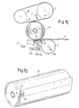
- the finished log is shown in Figure 1D .
- the loose tail end LF is folded and projects with respect to the line of adhesive A applied to the log. This facilitates opening of the log.
- the light adhesion caused by seepage of the adhesive on the outermost turn of web material is easily overcome by traction without the material breaking. This allows easy opening of the roll without the risk of the web material tearing along the first and perhaps also the subsequent turns.
- the double thickness of the end, due folding thereof guarantees the final user a better grip and a sensation of increased volume.
- the movable dispenser 21 in its movement to return downwards ( Figure 1 B) can follow a more flattened trajectory than the one shown, so that the part of adhesive or glue still present on the dispenser wets the stretch of web material folded between the strip of adhesive "A" and the folding line.
- Figures 4A, 4B and 4C show, in a schematic side view, a second embodiment of the method and of the device according to the invention.
- a supporting and rolling surface 3 on which the logs R are fed in a per se known way.
- Extending parallel to the surface 3 are a series of belts 9 entrained around rollers 7 and 10, while positioned under the supporting surface 3 is a roller 5, again equipped with annular raised portions 5R which project above the surface 3, through profiles defining said surface, or through slots produced in a continuous plate.
- the end portion of the supporting surface 3 has suction holes 13 in communication with a suction box 15 in the same way as described hereinbefore with reference to the previous example of embodiment.
- an adhesive dispenser Positioned along the surface 3 is an adhesive dispenser comprising a reservoir 19 of a liquid adhesive and a movable dispensing element indicated again with 21, in this case equipped with a lifting and lowering movement between a position immersed in the liquid adhesive in the reservoir 19 and a raised position, wherein it is flush with the supporting surface 3 or projects slightly therefrom, through a cross slot.
- a folding plate 3C oscillating about a horizontal axis 3B, parallel to the axis of the logs R.
- the device described hereinbefore with reference to Figures 4A, 4B and 4C operates as follows.
- the log R is fed between the lower branch of the belts 9 and the supporting surface 3 and is positioned in the arrangement shown in figure 4A , with the loose tail end LF thereof unwound over the plate 3C and the suction portion (equipped with the holes 13) of the supporting and rolling surface.
- the numeral 17 again indicates the photocell that detects the position of the loose tail end of the log, while nozzles, not shown, similar to those shown at 11 are used to open the loose end with the same procedure as the one described with reference to Figures 1 and 2 .
- the log R is then made to roll, with consequent unwinding of the final portion of web material, until the back thereof is positioned above the glue reservoir 19 ( Figure 4B ).
- the movable dispensing element 21 is raised (optionally in advance with respect to arrival of the log R) to apply adhesive to the back of the log.
- the folding plate 3C is made to rotate (clockwise in the drawing) about the axis 3B to fold the loose tail end LF over itself ( Figure 4B ).
- the folded loose end LF is retained by suction through the holes 13.
- Movement of the rollers 7 and 10 and of the belt 9 is then inverted to cause at this point rolling of the log R in the opposite direction, rewinding of the previously unwound portion of web material and closing of the folded loose tail end LF, as well as ejection of the log from the supporting and rolling surface 3.
- the distance between the suction holes 13 on which the loose tail end LF is folded and the adhesive dispenser is such that the portion of web material unwound is slightly greater than the circumferential extension of the log. In this way, by rewinding the unwound portion of web material, with the tail end LF folded, this covers the strip (continuous or discontinuous) of adhesive applied to the surface of the log, guaranteeing adhesion of the loose end to the log ( Figure 4C ).
- a series of adhesive dispensing guns or dispensing nozzles can be provided in a position above the log, positioned at intervals between the belts 9 and the pulleys 10, 7. Once the folded tail end of appropriate length is positioned, the guns or nozzles dispense liquid adhesive on the back of the log, which will then be wound again as described above and shown in Figure 4C .
- FIGS 3A to 3D show a further variant of embodiment of the device and of the method according to the invention.
- the device again has a supporting and rolling surface 3, projecting through which are the annular raised portions 5R of a roller 5 arranged under said surface. Positioned above the surface 3 are the rollers 7 and 10, around which the belts 9 are driven. The end portion of the supporting surface 3 has suction holes 13 in connection with the suction box 15 below.
- the end portion of the supporting and rolling surface 3 is again associated with a folding plate 3C oscillating about an axis 3B.
- Associated with the roller 10 is an oscillating support 31 carrying a duct 33, with which a series of liquid adhesive nozzles 35 is associated.
- the adhesive is applied by activating the nozzles 35 which spray the necessary quantity of adhesive on the folded surface of the loose tail end LF, after this has reached the position in Figure 3C . It can be seen how the nozzles 35 are also made to oscillate to be oriented correctly towards the folded loose end to direct the adhesive thereon. Once the adhesive has been applied, the nozzles 35 are withdrawn with respect to the trajectory of the log R, which can be ejected by rotating the rollers 7 and 10 and then moving the belts 9 as shown in Figure 3D . Alternatively, with appropriate lengths of folded end, the nozzles 35 can direct the jet of glue towards the log, rather than towards the folded end, or towards the nip formed between log and folded end.
- Figure 5 shows a variant of embodiment similar to the embodiment in figures 3A to 3D , where nonetheless the adhesive, rather than being composed of a liquid glue, is in the form of a double-sided adhesive tape applied by a generic applicator 41 along the end edge B of the loose tail end LF of the web material unwound from the log R.
- the position of the piece of double sided adhesive tape is shown in detail in the schematic enlargement in Figure 6 .
- the double sided adhesive tape is placed overlapping the terminal edge B of the folded loose tail end LF. Rewinding of the folded loose end LF causes adhesion to the back of the log R.
- FIGS 7A, 7B and 7C and the enlargement in Figure 8 show a further variant of embodiment.
- the same numbers indicate the same or equivalent parts to those in the previous examples of embodiment.
- the log R is again positioned between the assembly formed by the rollers 7, 10 and by the belts 9 driven therearound and the supporting and rolling surface 3.
- the annular raised portions 5R of the lower roller 5 project through this surface.
- the suction holes 13 in connection with the suction box 15 retain the unwound portion of web material and in particular the loose end LF, which is folded by folding of a plate 3C about the axis 3B as shown in the examples in Figures 4A to 4C .
- liquid glue or adhesive is dispensed by means of a movable dispensing element 21 with a rectilinear portion 21 B, hinged oscillatingly about an axis lying below the surface 3.
- the movable dispensing element 21 is not used to fold over the loose tail end LF, which as stated is folded by the oscillating movement of the plate 3C.
- the sole function of the movable dispensing element 21 is to apply glue to the surface of the unwound web material facing towards the back of the log.
- FIGS 7A, 7B and 7C show the operating sequence.
- the loose end LF is positioned by means of the operations already described and with the use of the photocell 17 and air nozzles;
- the movable dispensing element 21 transfers the adhesive A to the desired position on the inner surface of the unwound portion of web material;
- the loose end LF is folded, i.e.
- Figures 9A and 9B show two operating steps of a device in a further embodiment, which forms a variant with respect to that illustrated in Figures 1A-1C .
- the same numbers indicate the same or equivalent parts to those in the example of embodiment in Figures 1A-1C .
- the adhesive is applied by a series of dispensing nozzles 16 positioned in the vicinity of the photocells 17 and optionally aligned and alternated therewith. Once the terminal end has been detected the dispensing nozzles 16 dispense adhesive on the loose end, as shown in Figure 9A .
- the end, folded as shown in Figure 9B by the oscillating element 21 (which in this case does not function as adhesive applicator), is glued to the inner surface of the web material. Part of the adhesive seeps through the thickness of the folded web material and causes the surface of the loose tail end facing the axis of the log to adhere to the surface of said log.
- the glue or adhesive can be distributed in restricted stretches or areas.
- the folded end can be sealed up to the folding line, while remaining easy for the final user to grip and detach. It is sufficient that the adhesive, for example in the configuration shown in Figure 3 , although sprayed up to the folding line, is not distributed over the entire surface, i.e. allows, for example, a finger to be inserted between two adjacent glued areas in the finished roll, so that the final user can grip the tail end and lift it from the wound roll.
- the dispenser can distribute adhesive according to broken stretches "A", instead of in the form of a continuous line.
- Figure 10 schematically shows a portion of a roll or log glued according to this method, i.e. with areas of glue or adhesive spaced from one another, which leave loose portions of web material that can be gripped easily to facilitate detachment from the roll.
- the discrete areas, aligned along a line parallel to the axis of the log, at the level of which the adhesive is applied, are indicated schematically with A.
Landscapes
- Replacement Of Web Rolls (AREA)
- Crushing And Grinding (AREA)
- Formation And Processing Of Food Products (AREA)
- Reduction Rolling/Reduction Stand/Operation Of Reduction Machine (AREA)
- Ceramic Products (AREA)
Abstract
Description
- The present invention relates to improvements to methods and devices to close, by gluing or adhesion, the tail end of rolls or logs of wound web material, such as logs of tissue paper to produce kitchen towels, toilet paper or the like.
- In the production of toilet paper, kitchen towels and other products made of absorbent paper or tissue paper for domestic or industrial use, a predetermined quantity of web material is wound into individual logs. The web material is usually delivered from reels of large diameter produced in paper mills. The logs of smaller diameter, which are produced in the rewinding machines, are optionally then divided into rolls of smaller axial length, i.e. of dimensions equivalent to the finished product that is subsequently packaged and distributed to the consumer. Once the log has been produced in the rewinding machine, the loose tail end of the wound web material must be glued or in any case made to adhere to the log or roll in order to facilitate subsequent handling through the various production steps till final packaging. If this were not performed the logs could become accidentally unwound and obstruct the subsequent converting operations performed before they are packaged.
- Various device and methods to perform gluing of the tail end of logs of web material have been studied; this operation has some critical aspects as, among other things, sufficiently efficacious seal of the loose end must be guaranteed in order to prevent obstacles during the subsequent process steps, while at the same time easy detachment of the loose end by the final user of the roll must also be guaranteed. Machines and methods to perform gluing of the loose tail end of logs of web material are described in the patents
USA N. RE 37039 RE 35729 ,5242525 ,5716489 ,6143111 ,5681421 ,6050519 ,6682623 and in other patents pertaining to the same technological sector. A method and an apparatus representing the closest prior art is disclosed inUS 3,912,571 . - The object of the present invention is to provide a device and a method for gluing the loose tail end of logs or rolls of web material, which on the one hand allow efficient gluing and on the other facilitate the subsequent step to open the roll by the final user.
- The object of a preferred embodiment of the invention is to produce a method and a device which make it possible to obtain gluing with which subsequent opening of the loose end of the roll is facilitated, without tearing of the web material forming the first turn wound on the roll.
- In substance, a first aspect of the invention provides for a method to close the tail end of a log of web material using an adhesive, comprising the steps of: unwinding a portion of the web material from the log; applying the adhesive; rewinding the portion of web material to make the tail end adhere to the log. Characteristically, the tail end is folded before being rewound on the log thereby forming a fold of web material, which forms a portion for gripping and detaching the web material from the roll at the time of use. This gripping and detaching area has a double thickness with respect to the web material, having been obtained by folding of the tail end and therefore has increased consistency and strength.
- In substance, a folded portion of web material is formed to define a double end to facilitate grip and opening the roll by the final user.
- According to an advantageous embodiment, the folded tail end forms a fold of web material, which projects beyond the adhesive when the tail end has been rewound on the log.
- In general, the tail end can be folded outwards, i.e. so that the terminal edge of the web material is on the outer surface of the closed log. Nonetheless, according to the preferred embodiment of the invention, the tail end is folded on the inner surface of the unwound portion of the web material, so that the terminal edge of the tail end is positioned inside the last turn of web material wound on the log. This inward folding of the tail end further facilitates opening of the log, as the risk of the first turn of web material tearing due to incomplete detachment from the subsequent turn is reduced substantially.
- The adhesive, which is used to close the loose end, preferably although not necessarily a liquid adhesive, is applied in proximity to the terminal edge of the tail end. Preferably, the adhesive is applied in proximity to the terminal edge of said end, on the surface of the material, which, after rewinding of the tail portion of web material, comes into contact with the outer surface of the log. However, in a per se known way, it would also be possible for the adhesive to be applied, after having partially unwound a quantity of web material exceeding the length of one turn, to the outer surface of the log, i.e. to a portion of the web material still wound on the log. In this case, after folding the loose end, the web material is rewound to cover the adhesive applied to the back of the log.
- The adhesive is preferably applied as close as possible to the terminal edge of the loose end, i.e. as close as possible to the position that this edge takes after folding of the loose tail end. In a possible embodiment of the invention, the adhesive is applied exactly corresponding to the terminal edge of the folded loose end, so that it projects in part on one side and in part on the other side with respect to the terminal edge of the end.
- In a modified embodiment of the invention, the adhesive can be in the form of a double-sided adhesive tape, although it is preferable to use an adhesive in the form of liquid glue. If the adhesive is in liquid form, it can be picked up, in a per se known way, by a movable dispensing element, which picks up the liquid adhesive from a reservoir or container and applies it to the desired point on the surface of the web material. In a possible embodiment of the invention, the movable dispensing element is also used to perform folding of the tail end, in order to reduce the movable members required to perform the operations to close the tail end.
- Although it is preferable for the adhesive to be applied at a certain distance from the folding line of the loose tail end, in order to keep a portion of folded web material projecting from the gluing line, to facilitate grip it would also be possible to distribute glue or adhesive up to the folding line according to a continuous line or in stretches, due to the form of the dispenser or the operating mode thereof, as will be explained hereunder.
- The adhesive can be applied according to a continuous line, or according to a discontinuous line, or yet again also in one or two points close to the fold of the loose tail end, to leave stretches of material loose and easily gripped by the fingers of the user at the time the roll is opened, when it is used for the first time.
- According to a different aspect, the invention relates to a device for closing the tail end of logs of web material, comprising a system for unwinding a portion of web material from the log and a system for rewinding the tail end on the log after the adhesive has been applied, and a folding member to fold the tail end and form a fold of web material adjacent to the adhesive after the tail end has been rewound and made to adhere to the log.
- Further advantageous characteristic embodiments of the method and of the device according to the invention are indicated in the appended claims.
- The invention also relates to a log of wound web material, with a tail end fastened by means of an adhesive to the surface of the log, wherein said tail end is folded and forms a fold defining a portion for gripping and detaching the folded end from the log. This portion has double thickness compared to the thickness of the base web material.
- Further characteristics and embodiments of the log, according to the invention, are indicated in the appended claims.
- The invention will be better understood following the description of the accompanying drawing, which shows non-limiting practical embodiments of the invention. More specifically, in the drawing, where the same parts are indicated with the same reference numeral:
-
Figures 1A, 1B and1C show, in schematic side views, three steps to apply the adhesive to the folded loose tail end of a log in a first embodiment; -
Figure 1D shows an enlarged perspective view of the log obtained with the method illustrated inFigures 1A, 1B and1C ; -
Figures 2A, 2B and2C show axonometric views of the device inFigures 1A, 1B and1C in three steps of the process to close the tail end; -
Figures 3A, 3B ,3C and 3D show axonometric views of three operating steps of a different embodiment of the device according to the invention; -
Figures 4A, 4B and4C show a schematic side view of three operating steps of a further device according to the invention; -
Figure 5 shows a schematic side view of a further embodiment of the invention; -
Figure 6 shows a schematic enlargement of the area for application of the adhesive in the device inFigure 5 ; -
Figures 7A, 7B and7C shows a sequence of the operating cycle of a further device according to the invention; -
Figure 8 shows a schematic enlargement of the area for application of the adhesive in the device inFigures 7A, 7B and7C ; -
Figures 9A and 9B show a variant of embodiment in two moments of the operating cycle; and -
Figure 10 schematically shows a log in a different configuration, with discontinuous distribution of the glue. - A first embodiment of the invention is represented in side view and in axonometric view in
Figures 1A to 2C . In this embodiment, the device to close the tail end of the log R substantially comprises a supporting and rollingsurface 3 on which the log R is fed in a per se known way, not shown, e.g. by a rotary butterfly distributor. - Positioned in the final area of the supporting and rolling
surface 3 is alower roller 5 with anaxis 5A located below said surface. Theroller 5 has annular raisedportions 5R (see in particularFigures 2A, 2B and2C ), which project throughprofiles 3A, which define the supportingsurface 3. In this way the surface of theroller 5 projects partially beyond the supportingsurface 3 in order to come into contact with the log R. - Positioned above the
surface 3 is aroller 7, driven about which is a flexible member composed of a series ofbelts 9. Besides being entrained around theroller 7, the belts are entrained around afurther roller 10 parallel to theroller 7. At least one of the tworollers belts 9 and of therollers belts 9 with respect to the supportingsurface 3, as a function of the diameter of the logs to be glued. - The distance between the
roller 7 with thebelts 9 and theroller 5 is such that a log R can be inserted between these members, in contact with the annular raisedportions 5R of theroller 5 and thebelts 9. In this way it is possible to retain the log R in a controlled position and make it rotate in the desired direction to control opening and positioning of the tail end of said log, allowing the subsequent gluing operations. - Associated with the
roller 7 are a series ofnozzles 11 aligned parallel to the axis of therollers rollers Figures 1 and3 , below thenozzles 11 the supportingsurface 3 is tilted downwards and is equipped with a series of suction holes 13 in connection with asuction box 15 below. Positioned beyond the end area of the supportingsurface 3 is aphotocell 17 or another suitable sensor to detect in a per se known way the presence of the loose tail end unwound from the log R. - Also positioned under the tilted end portion of the supporting
surface 3 is acontainer 19 of adhesive in the form of a liquid glue, inside which a movable applicator element can be immersed, said element indicated as a whole with 21 and composed of a pair ofarms 21A supporting arectilinear member 21 B, such as a wire or a bar which is immersed in the liquid adhesive contained in thecontainer 19. - Operation of the device described hereinbefore is as follows. A log R is fed along the supporting and rolling
surface 3 and takes the position shown inFigure 1A , in contact inferiorly with the annular raisedportions 5R of theroller 5 and superiorly with thebelts 9 driven around theroller 7. It is then made to rotate in the direction of winding, according to the arrow f1, so that the loose tail end thereof passes in front of thenozzles 11, which generate jets of air directed tangentially against the surface of the log R. This allows the loose tail end to be opened by the jets of air and take the position indicated with LF inFigure 1A . In this position the end LF projects downwards beyond the end portion of the supporting and rollingsurface 3. If the portion of web material unwound from the log R is sufficiently long, the loose tail end LF intercepts the beam of the photocell 17 (e.g. normally reflected from a reflecting surface lying behind or from the surface of thelower roller 5 itself). - In this situation, the log R is made to continue to rotate in the rewinding direction f1 until the
photocell 17 detects the terminal edge B of the loose end LF and gives the command to stop rotation of therollers belts 9. If after opening of the loose tail end LF by thenozzles 11 the portion of unwound web material is not sufficiently long to intercept the beam of thephotocell 17, the direction of rotation of therollers suction box 15, at this point retains the unwound portion of web material adhering to the supportingsurface 3 to perform the gluing operation described with reference toFigures 1B ,1C ,2B ,2C . - Gluing takes place causing clockwise rotation (in the drawing) of the
movable dispensing element 21 about its own axis of oscillation, which is below the perforated suction portion of the supporting and rollingsurface 3. The loose tail end LF unwound from the log R is along the path of therectilinear portion 21 B of themovable dispensing element 21, so that the oscillating movement thereof takes theportion 21 B into contact with the outer surface of the web material at the level of the loose tail end LF and, continuing rotation, causes folding of the loose tail end LF on thesurface 3, at the level of the suction holes 13, as shown inFigures 1B and2B . - Suction through the
holes 13 also retains the loose tail end LF thus folded, thanks to the fact that the web material of which the log R is composed is sufficiently permeable to air. Consequently, during reverse rotation of themovable dispensing element 21, the folded loose end LF, rather than moving backwards due to said reverse rotation, remains in the position inFigure 1B , with a strip of adhesive A applied by theportion 21 B of themovable dispensing element 21 to the surface thereof facing the log R. - After this operation, the
roller 5 remains stationary, while theroller 7, theroller 10 and thebelts 9 are made to rotate in the direction indicated inFigure 1C to cause ejection of the log R, which is made to roll between the lower branch of thebelts 9 and the tilted and perforated end portion of the supporting and rollingsurface 3. The roll R is thus ejected, simultaneously causing closing of the folded end LF on the outer surface of the log R by gluing by the strip of adhesive A. The adhesive A optionally seeps partially through the folded portion of the loose tail end LF to cause slight adhesion also of the outer layer of web material forming the folded end. - The finished log is shown in
Figure 1D . The loose tail end LF is folded and projects with respect to the line of adhesive A applied to the log. This facilitates opening of the log. When the final user grips the folded loose end and detaches it from the roll, the light adhesion caused by seepage of the adhesive on the outermost turn of web material is easily overcome by traction without the material breaking. This allows easy opening of the roll without the risk of the web material tearing along the first and perhaps also the subsequent turns. At the same time, the double thickness of the end, due folding thereof, guarantees the final user a better grip and a sensation of increased volume. - If the folded end is required to be glued up to the end thereof, i.e. up to the point of folding, in the case in
Figures 1 and2 , themovable dispenser 21, in its movement to return downwards (Figure 1 B) can follow a more flattened trajectory than the one shown, so that the part of adhesive or glue still present on the dispenser wets the stretch of web material folded between the strip of adhesive "A" and the folding line. In this way the remaining filaments of liquid adhesive or glue will be deposited on the part of the web material that will form the end for the final user to grip, guaranteeing very light adhesion of the folded end to the log, to guarantee sufficient seal to avoid problems during subsequent operations (cutting, transport, packaging, etc.) which at the same time does not obstruct gripping and detaching by the final user. -
Figures 4A, 4B and4C show, in a schematic side view, a second embodiment of the method and of the device according to the invention. Also in this example of embodiment there is a supporting and rollingsurface 3, on which the logs R are fed in a per se known way. Extending parallel to thesurface 3 are a series ofbelts 9 entrained aroundrollers surface 3 is aroller 5, again equipped with annular raisedportions 5R which project above thesurface 3, through profiles defining said surface, or through slots produced in a continuous plate. The end portion of the supportingsurface 3 has suction holes 13 in communication with asuction box 15 in the same way as described hereinbefore with reference to the previous example of embodiment. - Positioned along the
surface 3 is an adhesive dispenser comprising areservoir 19 of a liquid adhesive and a movable dispensing element indicated again with 21, in this case equipped with a lifting and lowering movement between a position immersed in the liquid adhesive in thereservoir 19 and a raised position, wherein it is flush with the supportingsurface 3 or projects slightly therefrom, through a cross slot. - Provided beyond the perforated suction portion of the
surface 3, is afolding plate 3C oscillating about ahorizontal axis 3B, parallel to the axis of the logs R. - The device described hereinbefore with reference to
Figures 4A, 4B and4C operates as follows. The log R is fed between the lower branch of thebelts 9 and the supportingsurface 3 and is positioned in the arrangement shown infigure 4A , with the loose tail end LF thereof unwound over theplate 3C and the suction portion (equipped with the holes 13) of the supporting and rolling surface. The numeral 17 again indicates the photocell that detects the position of the loose tail end of the log, while nozzles, not shown, similar to those shown at 11 are used to open the loose end with the same procedure as the one described with reference toFigures 1 and2 . - The log R is then made to roll, with consequent unwinding of the final portion of web material, until the back thereof is positioned above the glue reservoir 19 (
Figure 4B ). Themovable dispensing element 21 is raised (optionally in advance with respect to arrival of the log R) to apply adhesive to the back of the log. Simultaneously, or in any case in a moment of time synchronized with application of the adhesive, thefolding plate 3C is made to rotate (clockwise in the drawing) about theaxis 3B to fold the loose tail end LF over itself (Figure 4B ). The folded loose end LF is retained by suction through theholes 13. Movement of therollers belt 9 is then inverted to cause at this point rolling of the log R in the opposite direction, rewinding of the previously unwound portion of web material and closing of the folded loose tail end LF, as well as ejection of the log from the supporting and rollingsurface 3. The distance between the suction holes 13 on which the loose tail end LF is folded and the adhesive dispenser is such that the portion of web material unwound is slightly greater than the circumferential extension of the log. In this way, by rewinding the unwound portion of web material, with the tail end LF folded, this covers the strip (continuous or discontinuous) of adhesive applied to the surface of the log, guaranteeing adhesion of the loose end to the log (Figure 4C ). - Positioned beyond the
plate 3C, which has been suitably returned to the original position to allow delivery of the glued log R, is, for example, a conveyor belt or other member to remove the log thus sealed. The appearance of the log obtained is again the one illustrated schematically inFigure 1D . - In a possible alternative to the embodiment in
Figures 4A-C in place of the dispensing element 21 a series of adhesive dispensing guns or dispensing nozzles can be provided in a position above the log, positioned at intervals between thebelts 9 and thepulleys Figure 4C . -
Figures 3A to 3D show a further variant of embodiment of the device and of the method according to the invention. The same numbers indicated the same or equivalent parts to those in the previous examples of embodiment. - The device again has a supporting and rolling
surface 3, projecting through which are the annular raisedportions 5R of aroller 5 arranged under said surface. Positioned above thesurface 3 are therollers belts 9 are driven. The end portion of the supportingsurface 3 has suction holes 13 in connection with thesuction box 15 below. - The end portion of the supporting and rolling
surface 3 is again associated with afolding plate 3C oscillating about anaxis 3B. Associated with theroller 10 is anoscillating support 31 carrying aduct 33, with which a series of liquidadhesive nozzles 35 is associated. - Operation of the device is substantially the same as described hereinbefore with reference to the previous examples of embodiment, with regard to opening and folding of the loose tail end LF of the web material forming the log R, and closing thereof after application of the adhesive. In this case, however, the adhesive is applied by activating the
nozzles 35 which spray the necessary quantity of adhesive on the folded surface of the loose tail end LF, after this has reached the position inFigure 3C . It can be seen how thenozzles 35 are also made to oscillate to be oriented correctly towards the folded loose end to direct the adhesive thereon. Once the adhesive has been applied, thenozzles 35 are withdrawn with respect to the trajectory of the log R, which can be ejected by rotating therollers belts 9 as shown inFigure 3D . Alternatively, with appropriate lengths of folded end, thenozzles 35 can direct the jet of glue towards the log, rather than towards the folded end, or towards the nip formed between log and folded end. -
Figure 5 shows a variant of embodiment similar to the embodiment infigures 3A to 3D , where nonetheless the adhesive, rather than being composed of a liquid glue, is in the form of a double-sided adhesive tape applied by ageneric applicator 41 along the end edge B of the loose tail end LF of the web material unwound from the log R. The position of the piece of double sided adhesive tape is shown in detail in the schematic enlargement inFigure 6 . The double sided adhesive tape is placed overlapping the terminal edge B of the folded loose tail end LF. Rewinding of the folded loose end LF causes adhesion to the back of the log R. -
Figures 7A, 7B and7C and the enlargement inFigure 8 show a further variant of embodiment. The same numbers indicate the same or equivalent parts to those in the previous examples of embodiment. In this example the log R is again positioned between the assembly formed by therollers belts 9 driven therearound and the supporting and rollingsurface 3. The annular raisedportions 5R of thelower roller 5 project through this surface. The suction holes 13 in connection with thesuction box 15 retain the unwound portion of web material and in particular the loose end LF, which is folded by folding of aplate 3C about theaxis 3B as shown in the examples inFigures 4A to 4C . In this case the liquid glue or adhesive is dispensed by means of amovable dispensing element 21 with arectilinear portion 21 B, hinged oscillatingly about an axis lying below thesurface 3. Contrary to the description with reference toFigures 1A to 2C , nonetheless, in this case themovable dispensing element 21 is not used to fold over the loose tail end LF, which as stated is folded by the oscillating movement of theplate 3C. The sole function of themovable dispensing element 21 is to apply glue to the surface of the unwound web material facing towards the back of the log. - The arrangement is such that the liquid adhesive picked up by the
movable dispensing element 21 in thereservoir 19 is applied at the level of the area in which the terminal or end edge B of the loose end LF will be positioned after folding.Figures 7A, 7B and7C show the operating sequence. InFigure 7A , the loose end LF is positioned by means of the operations already described and with the use of thephotocell 17 and air nozzles; inFigure 7B themovable dispensing element 21 transfers the adhesive A to the desired position on the inner surface of the unwound portion of web material; inFigure 7C the loose end LF is folded, i.e. folded over against the inner surface of the remaining portion of unwound web material and is positioned with the end edge B approximately in the center of the strip of adhesive A applied previously, as shown in the schematic enlargement inFigure 8 . Subsequent rolling of the log R allows ejection of said log and closing thereof through rewinding of the previously unwound portion of web material. -
Figures 9A and 9B show two operating steps of a device in a further embodiment, which forms a variant with respect to that illustrated inFigures 1A-1C . The same numbers indicate the same or equivalent parts to those in the example of embodiment inFigures 1A-1C . In this example of embodiment, the adhesive is applied by a series of dispensingnozzles 16 positioned in the vicinity of thephotocells 17 and optionally aligned and alternated therewith. Once the terminal end has been detected the dispensingnozzles 16 dispense adhesive on the loose end, as shown inFigure 9A . The end, folded as shown inFigure 9B by the oscillating element 21 (which in this case does not function as adhesive applicator), is glued to the inner surface of the web material. Part of the adhesive seeps through the thickness of the folded web material and causes the surface of the loose tail end facing the axis of the log to adhere to the surface of said log. - In all the cases illustrated it is possible to distribute the glue or adhesive in a strip or complete area, or in stretches or limited areas. In particular, in the examples in
Figures 3 ,4 ,5 and 6 , the glue or adhesive can be distributed in restricted stretches or areas. In all these cases the folded end can be sealed up to the folding line, while remaining easy for the final user to grip and detach. It is sufficient that the adhesive, for example in the configuration shown inFigure 3 , although sprayed up to the folding line, is not distributed over the entire surface, i.e. allows, for example, a finger to be inserted between two adjacent glued areas in the finished roll, so that the final user can grip the tail end and lift it from the wound roll. - Similarly, in the example in
Figures 5 and 6 , it is sufficient that the double-sided adhesive tape "A" is distributed in short stretches and with the left-hand part inFigure 6 extended up to the folding line. - Also similarly, in the example in
Figure 4 the dispenser can distribute adhesive according to broken stretches "A", instead of in the form of a continuous line. - In all these cases (adhesive in stretches or in areas), by suitably staggering the areas provided with adhesive with the cut of the logs into rolls of appropriate length, it is possible to make the glued areas coincide with those without glue, with the side and central parts of each roll respectively (or vice versa), to obtain rolls which offer the final user areas to grip and lift the tail end in the center or on the side parts of said roll, respectively.
-
Figure 10 schematically shows a portion of a roll or log glued according to this method, i.e. with areas of glue or adhesive spaced from one another, which leave loose portions of web material that can be gripped easily to facilitate detachment from the roll. The discrete areas, aligned along a line parallel to the axis of the log, at the level of which the adhesive is applied, are indicated schematically with A. - It is understood that the drawing merely shows possible examples of embodiment of the invention, which can vary in forms and arrangements without however departing from the scope of the concept on which said invention is based. Any reference numerals in the appended claims are provided to facilitate reading of the claims with reference to the description and to the drawing, and do not limit the scope of protection represented by the claims.
Claims (21)
- A method for closing the tail end of a log of web material using an adhesive, comprising the steps of: unwinding a portion of the web material from the log; applying said adhesive; rewinding said portion of web material to make the tail end adhere to the log, wherein said tail end is folded before being rewound on the log, thereby forming a fold of web material which forms a portion for gripping and detaching the folded end from the roll, characterized in that said adhesive is dispensed at the level of a supporting surface of the log and that said adhesive is applied by means of a movable dispensing element, which picks up adhesive from a container and applies it to the unwound web material
- Method as claimed in claim 1, characterized in that the fold of the web material projects beyond the adhesive when the tail end has been rewound on the log.
- Method as claimed in claim 1 or 2, characterized in that said tail end is folded on the inner surface of the unwound portion of said web material, the end edge of the tail end being positioned inside the last turn of web material wound on the log.
- Method as claimed in claim 1, 2 or 3, characterized in that said adhesive is applied to the tail end of the web material, in proximity to the terminal edge thereof, on the surface that comes into contact with the web material forming the log when said portion of web material is rewound.
- Method as claimed in claim 3, characterized in that the adhesive is applied at the level of the position taken by the terminal edge of the folded tail end, on a band extending along the longitudinal extension of the web material, on both sides of said terminal edge of the folded end.
- Method as claimed in one or more of the previous claims, characterized in that said adhesive is a liquid glue.
- Method as claimed in one or more of the previous claims, characterized in that said adhesive is applied by means of said movable dispensing element, extending parallel to the axis of the log with a movement towards the tail end of the log, said dispensing element applying the adhesive and folding the tail end.
- Method as claimed in one or more of claims 1 to 6, characterized in that said tail end is folded with a folding member separate from the dispensing element.
- Method as claimed in one or more of the previous claims, characterized in that said adhesive is distributed discontinuously.
- A device for closing the tail end of logs of web material, comprising: a system for unwinding a portion of web material from the log; a system for rewinding the tail end on the log after application of an adhesive; a folding member, to fold the tail end and form a fold of web material defining a portion for gripping and detaching the folded loose end from the roll; characterized in that said folding member comprises an adhesive dispensing element, which with its movement applies adhesive to the tail end and causes folding thereof.
- Device as claimed in claim 10, characterized in that the folding member is arranged and designed such as to form in the loose tail end a fold of web material projecting beyond the adhesive, after the tail end has be rewound and adhered to the log.
- Device as claimed in claim 10 or 11, characterized in that said folding member is arranged and designed to fold the tail end of the log on the inner surface of said unwound portion of web material, to position the terminal edge of the tail end inside the last turn of web material wound on the log.
- Device as claimed in one or more of claims 10 to 12, characterized in that said dispensing element is equipped with an oscillatory movement between a position of immersion in a container of liquid adhesive and a position of folding over of the tail end.
- Device as claimed in one or more of claims 10 to 13, characterized in that it comprises a supporting surface of the log, with an end with which said folding member is associated.
- Device as claimed in claims 14, characterized in that said dispensing element is positioned at the level of the end of the supporting surface of the log and with its oscillatory movement takes a path which intercepts the loose end of the web material when this projects beyond the end of said supporting surface, the path terminating against said surface, on which the dispensing element folds over the tail end of the web material, the axis of oscillation of the dispensing element being on the opposite side of said supporting surface with respect to the web material.
- Device as claimed in claim 14, characterized in that an adhesive dispenser, which applies adhesive to the outer surface of the log, is positioned along said supporting surface.
- Device as claimed in one or more of claims 10 to 16, characterized in that means to cause controlled rolling of the log along the supporting surface and members to open the loose end, to position the loose end for application of the adhesive, are positioned along said supporting surface of the logs.
- Device as claimed in claim 17, characterized in that said means to cause controlled rolling comprise at least one flexible member parallel to at least one portion of said surface, with a path for passage of the logs extending between the supporting surface and said flexible member.
- Device as claimed in claim 17 or 18, characterized in that said means to cause controlled rolling of the log comprise a pair of rollers.
- Device as claimed in claim 18, characterized in that a first roller is positioned with the axis thereof on one side of the surface, the path of the logs passing between said first roller and said supporting surface, and a second roller is positioned with the axis thereof on the opposite side of the surface and projects from said surface towards the path of the logs.
- Device as claimed in one or more of claims 10 to 20, characterized in that it has adhesive applicator means to apply said adhesive discontinuously.
Applications Claiming Priority (2)
| Application Number | Priority Date | Filing Date | Title |
|---|---|---|---|
| IT000273A ITFI20040273A1 (en) | 2004-12-28 | 2004-12-28 | DEVICE AND METHOD FOR THE CLOSING OF THE FINAL BLOCK OF ROLLS OF MATTRIFIED AND RELATED MATERIALS WITH ITS ROLLS |
| PCT/IT2005/000766 WO2006070431A1 (en) | 2004-12-28 | 2005-12-27 | Device and method for closing the tail end of logs of web material and relative logs obtained therewith |
Publications (2)
| Publication Number | Publication Date |
|---|---|
| EP1831090A1 EP1831090A1 (en) | 2007-09-12 |
| EP1831090B1 true EP1831090B1 (en) | 2010-10-13 |
Family
ID=35999513
Family Applications (1)
| Application Number | Title | Priority Date | Filing Date |
|---|---|---|---|
| EP05823561A Not-in-force EP1831090B1 (en) | 2004-12-28 | 2005-12-27 | Device and method for closing the tail end of logs of web material and relative logs obtained therewith |
Country Status (6)
| Country | Link |
|---|---|
| US (1) | US7846286B2 (en) |
| EP (1) | EP1831090B1 (en) |
| AT (1) | ATE484475T1 (en) |
| DE (1) | DE602005024172D1 (en) |
| IT (1) | ITFI20040273A1 (en) |
| WO (1) | WO2006070431A1 (en) |
Cited By (1)
| Publication number | Priority date | Publication date | Assignee | Title |
|---|---|---|---|---|
| CN109641711A (en) * | 2016-07-18 | 2019-04-16 | 法比奥·泼尼股份公司 | For sealing the machine and method of the reel tail end of web material |
Families Citing this family (15)
| Publication number | Priority date | Publication date | Assignee | Title |
|---|---|---|---|---|
| US7811648B2 (en) * | 2004-03-15 | 2010-10-12 | Georgia-Pacific Consumer Products Lp | Reduced ply separation tail seal |
| US8002927B2 (en) | 2006-06-23 | 2011-08-23 | The Procter & Gamble Company | Process for gluing the tail of a convolutely wound web material thereto |
| DE102007008996B4 (en) * | 2007-02-23 | 2017-12-28 | Sca Hygiene Products Gmbh | Product roll and apparatus for making such a product roll |
| ITFI20070087A1 (en) | 2007-04-13 | 2008-10-14 | Perini Fabio Spa | METHOD AND DEVICE FOR CLOSING THE FINAL FREE FLUB OF A ROLL OF MATTRIFIED AND ROLLED MATERIAL |
| GB2456328A (en) * | 2008-01-11 | 2009-07-15 | Usg Interiors Inc | Grid members for a suspended ceiling and methods of making same |
| USD668352S1 (en) | 2008-01-11 | 2012-10-02 | Usg Interiors, Llc | Suspended ceiling wall angle |
| IT1391420B1 (en) * | 2008-09-24 | 2011-12-23 | Perini Fabio Spa | "REWINDING MACHINE AND WINDING METHOD" |
| ITFI20120156A1 (en) | 2012-07-27 | 2014-01-28 | Perini Fabio Spa | "MACHINE TO CLOSE THE FINAL HALF OF A ROLL OF RIBBED MATERIAL" |
| US9675216B2 (en) | 2013-03-13 | 2017-06-13 | The Procter & Gamble Company | Convolutely wound material |
| US9352921B2 (en) | 2014-03-26 | 2016-05-31 | Kimberly-Clark Worldwide, Inc. | Method and apparatus for applying adhesive to a moving web being wound into a roll |
| US10351377B2 (en) | 2015-08-03 | 2019-07-16 | Elsner Engineering Works, Inc. | Ultrasonic roll tail closure of non-woven web material method and apparatus |
| CN105293196B (en) * | 2015-11-12 | 2018-08-07 | 佛山市南海区德昌誉机械制造有限公司 | A kind of reel protects the method and reel of envelope volume without rubber ring |
| CN108328272B (en) * | 2018-03-07 | 2024-01-12 | 佛山达健实验设备有限公司 | Coiled material tail end directional conveying device |
| US11694501B2 (en) | 2020-02-17 | 2023-07-04 | True Manufacturing Co., Inc. | Refrigerated vending system and method |
| NL2028434B1 (en) * | 2021-06-11 | 2022-12-20 | Ig Design Group B V | Wrapping material roll and method for production thereof |
Family Cites Families (15)
| Publication number | Priority date | Publication date | Assignee | Title |
|---|---|---|---|---|
| US3172612A (en) * | 1962-06-25 | 1965-03-09 | Fmc Corp | Apparatus for and method of sealing the ends of wound rolls of sheet material |
| US3912571A (en) * | 1974-06-03 | 1975-10-14 | Crown Zellerbach Corp | Roll product with manually graspable tail end and manufacture thereof |
| IT1241807B (en) * | 1990-10-17 | 1994-02-01 | Perini Navi Spa | EQUIPMENT FOR GLUING THE FINAL FLAP OF ROLLS OF TAPE MATERIAL |
| IT1252896B (en) * | 1991-11-08 | 1995-07-05 | Perini Fabio Spa | IMPROVED EQUIPMENT FOR GLUING THE FINAL EDGE OF ROLLS OF TAPE MATERIAL |
| IT1267563B1 (en) * | 1993-12-10 | 1997-02-05 | Perini Fabio Spa | GLUE DISPENSER AND DEVICE USING THE REGULATOR |
| WO1995015903A1 (en) * | 1993-12-10 | 1995-06-15 | Fabio Perini S.P.A. | Device for gluing the tail end of a reel of web material with vacuum systems for opening the tail end |
| DE19528264A1 (en) | 1994-08-02 | 1996-04-04 | Tela Papierfabrik Ag | Paper roll with end sheet closure |
| US5573615A (en) | 1995-05-09 | 1996-11-12 | Paper Converting Machine Company | Method and apparatus for tail sealing of convolutely wound webs |
| EP0868378B1 (en) * | 1995-11-28 | 2002-08-07 | FABIO PERINI S.p.A. | Method and device for measuring the diameter of a roll of web material |
| IT1286563B1 (en) * | 1996-03-05 | 1998-07-15 | Perini Fabio Spa | REWINDING MACHINE INCORPORATING A GLUER FOR THE COMPLETED ROLLS AND RELATIVE WINDING METHOD |
| IT1308272B1 (en) * | 1999-04-16 | 2001-12-10 | Perini Fabio Spa | DEVICE FOR GLUING ROLLS OF TAPE MATERIAL AND RELATED METHOD |
| JP2001120459A (en) * | 1999-10-29 | 2001-05-08 | Takashi Amano | Toilet paper roll |
| US6372064B1 (en) * | 1999-12-13 | 2002-04-16 | C. G. Bretting Manufacturing Company, Inc. | Tail sealer apparatus and method |
| US6882623B1 (en) * | 2000-02-08 | 2005-04-19 | Native Networks Technologies Ltd. | Multi-level scheduling method for multiplexing packets in a communications network |
| US7811648B2 (en) * | 2004-03-15 | 2010-10-12 | Georgia-Pacific Consumer Products Lp | Reduced ply separation tail seal |
-
2004
- 2004-12-28 IT IT000273A patent/ITFI20040273A1/en unknown
-
2005
- 2005-12-27 US US11/794,091 patent/US7846286B2/en not_active Expired - Fee Related
- 2005-12-27 DE DE602005024172T patent/DE602005024172D1/en active Active
- 2005-12-27 EP EP05823561A patent/EP1831090B1/en not_active Not-in-force
- 2005-12-27 WO PCT/IT2005/000766 patent/WO2006070431A1/en active Application Filing
- 2005-12-27 AT AT05823561T patent/ATE484475T1/en not_active IP Right Cessation
Cited By (2)
| Publication number | Priority date | Publication date | Assignee | Title |
|---|---|---|---|---|
| CN109641711A (en) * | 2016-07-18 | 2019-04-16 | 法比奥·泼尼股份公司 | For sealing the machine and method of the reel tail end of web material |
| CN109641711B (en) * | 2016-07-18 | 2021-01-29 | 法比奥·泼尼股份公司 | Machine and method for sealing the tail end of a log of web material |
Also Published As
| Publication number | Publication date |
|---|---|
| US7846286B2 (en) | 2010-12-07 |
| US20080083521A1 (en) | 2008-04-10 |
| DE602005024172D1 (en) | 2010-11-25 |
| ITFI20040273A1 (en) | 2005-03-28 |
| WO2006070431A1 (en) | 2006-07-06 |
| EP1831090A1 (en) | 2007-09-12 |
| ATE484475T1 (en) | 2010-10-15 |
Similar Documents
| Publication | Publication Date | Title |
|---|---|---|
| EP1831090B1 (en) | Device and method for closing the tail end of logs of web material and relative logs obtained therewith | |
| AU2003288734B2 (en) | Rewinding machine with gluing device to glue the final edge of the log formed and relative winding method | |
| US8585846B2 (en) | Method and device for closing the tail end of a log of web material and log obtained | |
| EP1888441B1 (en) | Machine and method for the production of rolls of weblike material | |
| US7896284B2 (en) | Method and machine for the production of logs of wound web material | |
| US20090302146A1 (en) | Rewinding Machine, Method for Producing Logs of Web Material | |
| EP1652804B1 (en) | Gluing device of an end edge of a log and relative gluing method | |
| KR100624260B1 (en) | Device for gluing rolls of web material and associated method | |
| CA2175145C (en) | Method and apparatus for tail sealing of convolutely wound webs | |
| US5800652A (en) | Method and apparatus for tail sealing of convolutely wound webs | |
| AU2006351174A1 (en) | Device for gluing a tail cant of a roll and product roll | |
| JP2001072288A (en) | Winding shaft loading method using web wound body continuous manufacturing machine and winding shaft loading device in web wound body continuous manufacturing machine | |
| EP3429929A1 (en) | Method and apparatus for banding rolls with paper |
Legal Events
| Date | Code | Title | Description |
|---|---|---|---|
| PUAI | Public reference made under article 153(3) epc to a published international application that has entered the european phase |
Free format text: ORIGINAL CODE: 0009012 |
|
| 17P | Request for examination filed |
Effective date: 20070606 |
|
| AK | Designated contracting states |
Kind code of ref document: A1 Designated state(s): AT BE BG CH CY CZ DE DK EE ES FI FR GB GR HU IE IS IT LI LT LU LV MC NL PL PT RO SE SI SK TR |
|
| DAX | Request for extension of the european patent (deleted) | ||
| 17Q | First examination report despatched |
Effective date: 20090902 |
|
| GRAP | Despatch of communication of intention to grant a patent |
Free format text: ORIGINAL CODE: EPIDOSNIGR1 |
|
| GRAS | Grant fee paid |
Free format text: ORIGINAL CODE: EPIDOSNIGR3 |
|
| GRAA | (expected) grant |
Free format text: ORIGINAL CODE: 0009210 |
|
| AK | Designated contracting states |
Kind code of ref document: B1 Designated state(s): AT BE BG CH CY CZ DE DK EE ES FI FR GB GR HU IE IS IT LI LT LU LV MC NL PL PT RO SE SI SK TR |
|
| REG | Reference to a national code |
Ref country code: GB Ref legal event code: FG4D |
|
| REG | Reference to a national code |
Ref country code: CH Ref legal event code: EP |
|
| REG | Reference to a national code |
Ref country code: IE Ref legal event code: FG4D |
|
| REF | Corresponds to: |
Ref document number: 602005024172 Country of ref document: DE Date of ref document: 20101125 Kind code of ref document: P |
|
| PGFP | Annual fee paid to national office [announced via postgrant information from national office to epo] |
Ref country code: FR Payment date: 20101210 Year of fee payment: 6 |
|
| REG | Reference to a national code |
Ref country code: NL Ref legal event code: VDEP Effective date: 20101013 |
|
| LTIE | Lt: invalidation of european patent or patent extension |
Effective date: 20101013 |
|
| PGFP | Annual fee paid to national office [announced via postgrant information from national office to epo] |
Ref country code: GB Payment date: 20101222 Year of fee payment: 6 |
|
| PG25 | Lapsed in a contracting state [announced via postgrant information from national office to epo] |
Ref country code: LT Free format text: LAPSE BECAUSE OF FAILURE TO SUBMIT A TRANSLATION OF THE DESCRIPTION OR TO PAY THE FEE WITHIN THE PRESCRIBED TIME-LIMIT Effective date: 20101013 |
|
| PG25 | Lapsed in a contracting state [announced via postgrant information from national office to epo] |
Ref country code: LV Free format text: LAPSE BECAUSE OF FAILURE TO SUBMIT A TRANSLATION OF THE DESCRIPTION OR TO PAY THE FEE WITHIN THE PRESCRIBED TIME-LIMIT Effective date: 20101013 Ref country code: SE Free format text: LAPSE BECAUSE OF FAILURE TO SUBMIT A TRANSLATION OF THE DESCRIPTION OR TO PAY THE FEE WITHIN THE PRESCRIBED TIME-LIMIT Effective date: 20101013 Ref country code: NL Free format text: LAPSE BECAUSE OF FAILURE TO SUBMIT A TRANSLATION OF THE DESCRIPTION OR TO PAY THE FEE WITHIN THE PRESCRIBED TIME-LIMIT Effective date: 20101013 Ref country code: FI Free format text: LAPSE BECAUSE OF FAILURE TO SUBMIT A TRANSLATION OF THE DESCRIPTION OR TO PAY THE FEE WITHIN THE PRESCRIBED TIME-LIMIT Effective date: 20101013 Ref country code: SI Free format text: LAPSE BECAUSE OF FAILURE TO SUBMIT A TRANSLATION OF THE DESCRIPTION OR TO PAY THE FEE WITHIN THE PRESCRIBED TIME-LIMIT Effective date: 20101013 Ref country code: AT Free format text: LAPSE BECAUSE OF FAILURE TO SUBMIT A TRANSLATION OF THE DESCRIPTION OR TO PAY THE FEE WITHIN THE PRESCRIBED TIME-LIMIT Effective date: 20101013 Ref country code: IS Free format text: LAPSE BECAUSE OF FAILURE TO SUBMIT A TRANSLATION OF THE DESCRIPTION OR TO PAY THE FEE WITHIN THE PRESCRIBED TIME-LIMIT Effective date: 20110213 Ref country code: PT Free format text: LAPSE BECAUSE OF FAILURE TO SUBMIT A TRANSLATION OF THE DESCRIPTION OR TO PAY THE FEE WITHIN THE PRESCRIBED TIME-LIMIT Effective date: 20110214 Ref country code: BG Free format text: LAPSE BECAUSE OF FAILURE TO SUBMIT A TRANSLATION OF THE DESCRIPTION OR TO PAY THE FEE WITHIN THE PRESCRIBED TIME-LIMIT Effective date: 20110113 |
|
| PGFP | Annual fee paid to national office [announced via postgrant information from national office to epo] |
Ref country code: DE Payment date: 20101220 Year of fee payment: 6 Ref country code: IT Payment date: 20101228 Year of fee payment: 6 |
|
| PG25 | Lapsed in a contracting state [announced via postgrant information from national office to epo] |
Ref country code: GR Free format text: LAPSE BECAUSE OF FAILURE TO SUBMIT A TRANSLATION OF THE DESCRIPTION OR TO PAY THE FEE WITHIN THE PRESCRIBED TIME-LIMIT Effective date: 20110114 Ref country code: BE Free format text: LAPSE BECAUSE OF FAILURE TO SUBMIT A TRANSLATION OF THE DESCRIPTION OR TO PAY THE FEE WITHIN THE PRESCRIBED TIME-LIMIT Effective date: 20101013 |
|
| PG25 | Lapsed in a contracting state [announced via postgrant information from national office to epo] |
Ref country code: EE Free format text: LAPSE BECAUSE OF FAILURE TO SUBMIT A TRANSLATION OF THE DESCRIPTION OR TO PAY THE FEE WITHIN THE PRESCRIBED TIME-LIMIT Effective date: 20101013 Ref country code: MC Free format text: LAPSE BECAUSE OF NON-PAYMENT OF DUE FEES Effective date: 20101231 Ref country code: ES Free format text: LAPSE BECAUSE OF FAILURE TO SUBMIT A TRANSLATION OF THE DESCRIPTION OR TO PAY THE FEE WITHIN THE PRESCRIBED TIME-LIMIT Effective date: 20110124 Ref country code: CZ Free format text: LAPSE BECAUSE OF FAILURE TO SUBMIT A TRANSLATION OF THE DESCRIPTION OR TO PAY THE FEE WITHIN THE PRESCRIBED TIME-LIMIT Effective date: 20101013 |
|
| REG | Reference to a national code |
Ref country code: CH Ref legal event code: PL |
|
| PLBE | No opposition filed within time limit |
Free format text: ORIGINAL CODE: 0009261 |
|
| STAA | Information on the status of an ep patent application or granted ep patent |
Free format text: STATUS: NO OPPOSITION FILED WITHIN TIME LIMIT |
|
| PG25 | Lapsed in a contracting state [announced via postgrant information from national office to epo] |
Ref country code: PL Free format text: LAPSE BECAUSE OF FAILURE TO SUBMIT A TRANSLATION OF THE DESCRIPTION OR TO PAY THE FEE WITHIN THE PRESCRIBED TIME-LIMIT Effective date: 20101013 Ref country code: RO Free format text: LAPSE BECAUSE OF FAILURE TO SUBMIT A TRANSLATION OF THE DESCRIPTION OR TO PAY THE FEE WITHIN THE PRESCRIBED TIME-LIMIT Effective date: 20101013 Ref country code: DK Free format text: LAPSE BECAUSE OF FAILURE TO SUBMIT A TRANSLATION OF THE DESCRIPTION OR TO PAY THE FEE WITHIN THE PRESCRIBED TIME-LIMIT Effective date: 20101013 Ref country code: SK Free format text: LAPSE BECAUSE OF FAILURE TO SUBMIT A TRANSLATION OF THE DESCRIPTION OR TO PAY THE FEE WITHIN THE PRESCRIBED TIME-LIMIT Effective date: 20101013 |
|
| 26N | No opposition filed |
Effective date: 20110714 |
|
| PG25 | Lapsed in a contracting state [announced via postgrant information from national office to epo] |
Ref country code: LI Free format text: LAPSE BECAUSE OF NON-PAYMENT OF DUE FEES Effective date: 20101231 Ref country code: CH Free format text: LAPSE BECAUSE OF NON-PAYMENT OF DUE FEES Effective date: 20101231 Ref country code: IE Free format text: LAPSE BECAUSE OF NON-PAYMENT OF DUE FEES Effective date: 20101227 |
|
| REG | Reference to a national code |
Ref country code: DE Ref legal event code: R097 Ref document number: 602005024172 Country of ref document: DE Effective date: 20110714 |
|
| GBPC | Gb: european patent ceased through non-payment of renewal fee |
Effective date: 20111227 |
|
| PG25 | Lapsed in a contracting state [announced via postgrant information from national office to epo] |
Ref country code: CY Free format text: LAPSE BECAUSE OF FAILURE TO SUBMIT A TRANSLATION OF THE DESCRIPTION OR TO PAY THE FEE WITHIN THE PRESCRIBED TIME-LIMIT Effective date: 20101013 |
|
| REG | Reference to a national code |
Ref country code: FR Ref legal event code: ST Effective date: 20120831 |
|
| PG25 | Lapsed in a contracting state [announced via postgrant information from national office to epo] |
Ref country code: LU Free format text: LAPSE BECAUSE OF NON-PAYMENT OF DUE FEES Effective date: 20101227 Ref country code: HU Free format text: LAPSE BECAUSE OF FAILURE TO SUBMIT A TRANSLATION OF THE DESCRIPTION OR TO PAY THE FEE WITHIN THE PRESCRIBED TIME-LIMIT Effective date: 20110414 |
|
| REG | Reference to a national code |
Ref country code: DE Ref legal event code: R119 Ref document number: 602005024172 Country of ref document: DE Effective date: 20120703 |
|
| PG25 | Lapsed in a contracting state [announced via postgrant information from national office to epo] |
Ref country code: GB Free format text: LAPSE BECAUSE OF NON-PAYMENT OF DUE FEES Effective date: 20111227 Ref country code: DE Free format text: LAPSE BECAUSE OF NON-PAYMENT OF DUE FEES Effective date: 20120703 Ref country code: TR Free format text: LAPSE BECAUSE OF FAILURE TO SUBMIT A TRANSLATION OF THE DESCRIPTION OR TO PAY THE FEE WITHIN THE PRESCRIBED TIME-LIMIT Effective date: 20101013 |
|
| PG25 | Lapsed in a contracting state [announced via postgrant information from national office to epo] |
Ref country code: IT Free format text: LAPSE BECAUSE OF NON-PAYMENT OF DUE FEES Effective date: 20111227 |
|
| PG25 | Lapsed in a contracting state [announced via postgrant information from national office to epo] |
Ref country code: FR Free format text: LAPSE BECAUSE OF NON-PAYMENT OF DUE FEES Effective date: 20120102 |